1. Introduction
A magnetocaloric effect is exhibited by materials that undergo a change in their magnetic properties by the application of heat. In the same manner, the change in magnetic field can produce a desired change in temperature. This effect has been extensively researched in the field of magnetic refrigeration [
1,
2]. The change in temperature can be utilized to produce change in a magnetic field in order to produce mechanical motion. In this paper, different designs of thermomagnetic heat engines based on gadolinium are studied and compared. Moreover, their applications for scavenging waste heat in combination with a TENG, EMG, and piezoelectric generator (PENG) are also discussed [
3].
During the last two decades, the magnetocaloric effect has been extensively studied in the context of power generation from different types of waste or low temperature heat sources. This recent interest is due to the advent of materials that have a Curie temperature close to room temperature. Hsu et al. measured the conversion efficiencies of thermomagnetism for rare earth ferromagnetic materials [
4]. A low magnetic field of 3kOe was used in the experiment. The results showed that single crystal materials tend to provide lower efficiency as compared to poly-crystalline, unless the magnetic field is very large. Post et al. studied a novel Heusler alloy (Ni
45Co
5Mn
50Sn
10) for harnessing thermomagnetic energy [
5]. The relative efficiency of the multiphase Heusler alloy exceeds that of conventional gadolinium. In the presence of magnetic fields of 3kOe and 15kOe, the measured efficiencies were 15.9% and 63.8% of the Carnot limit, respectively.
Andreevskii et al. carried out experiments with a thermomagnetic heat engine using gadolinium and calculated its power with respect to total different loads on the engine. The engine was made with thin plates of gadolinium attached to a disk. In the presence of the magnetic field, and with the periodic cooling and heating of the gadolinium, the engine was able to produce mechanical motion. The engine produced a maximum power of 160 mW at a temperature difference of 52 °C between the hot and cold inlets [
6]. Ujihara et al. proposed an innovative design of a thermomagnetic heat engine to generate electrical power. The device itself converted thermal energy into mechanical energy, where piezoelectric materials can be further used to generate electricity. For a temperature difference of 50 K, the device was capable of producing electricity at a power density of 3.61 mW/cm
2. The FEA analysis in their study showed that the power density can be enhanced by up to an order by optimizing the thermal contacts of the device [
7].
Fan et al. presented the design of a flexible triboelectric generator (TEG) based on low cost polymers. The device generates electricity due to the friction between its working materials, polyester (PET) and Kapton films. The device was able to produce a maximum power output density of 10.4 mW/cm
3 at an output voltage of 3.3 V [
8]. Chandrasekhar et al. experimented with a TENG to extract energy from different human motions. The device was applicable in various forms adaptable to different daily life materials and could produce enough electricity for smart sensor-based applications. In particular, it was capable of lighting 60 LEDs connected in series [
9]. Lee et al. presented a very flexible TENG made from aluminum foils and ZnO nano-wires. It generated electricity from very subtle motions, such as light wind and wrinkling of the face. This allowed their TENG to be used for certain cases requiring a very precise smart deformation sensor [
10]. Guo et al. proposed a waterproof triboelectric-electromagnetic hybrid generator for harvesting mechanical energy in a harsh environment. They analyzed the output characteristics of TENG and EMG. As a result, it obtained a total short-circuit current of 2.3 mA, an open circuit voltage of 5 V at a rotation speed of 1600 rpm, and was able to charge a supercapacitor(20 mF) to 1 V in 22 s [
11]. Zeeshan et al. presented a method for converting low temperature waste heat into electrical energy using a gadolinium (Gd) based thermomagnetic engine. They applied two different types of generators to the rotating shaft of a thermomagnetic engine. As a result, the hybrid generator effectively produced a maximum output of 0.75 mW at a load resistance of 10 kΩ [
12].
In the present paper, the operating principle of a thermomagnetic heat engine has been extensively discussed with emphasis on the output performance and design. Furthermore, the application of different types (designs) of electric generators was tested in conjunction with the operation of thermomagnetic heat engines.
2. Operating Principle of a Thermomagnetic Heat Engine
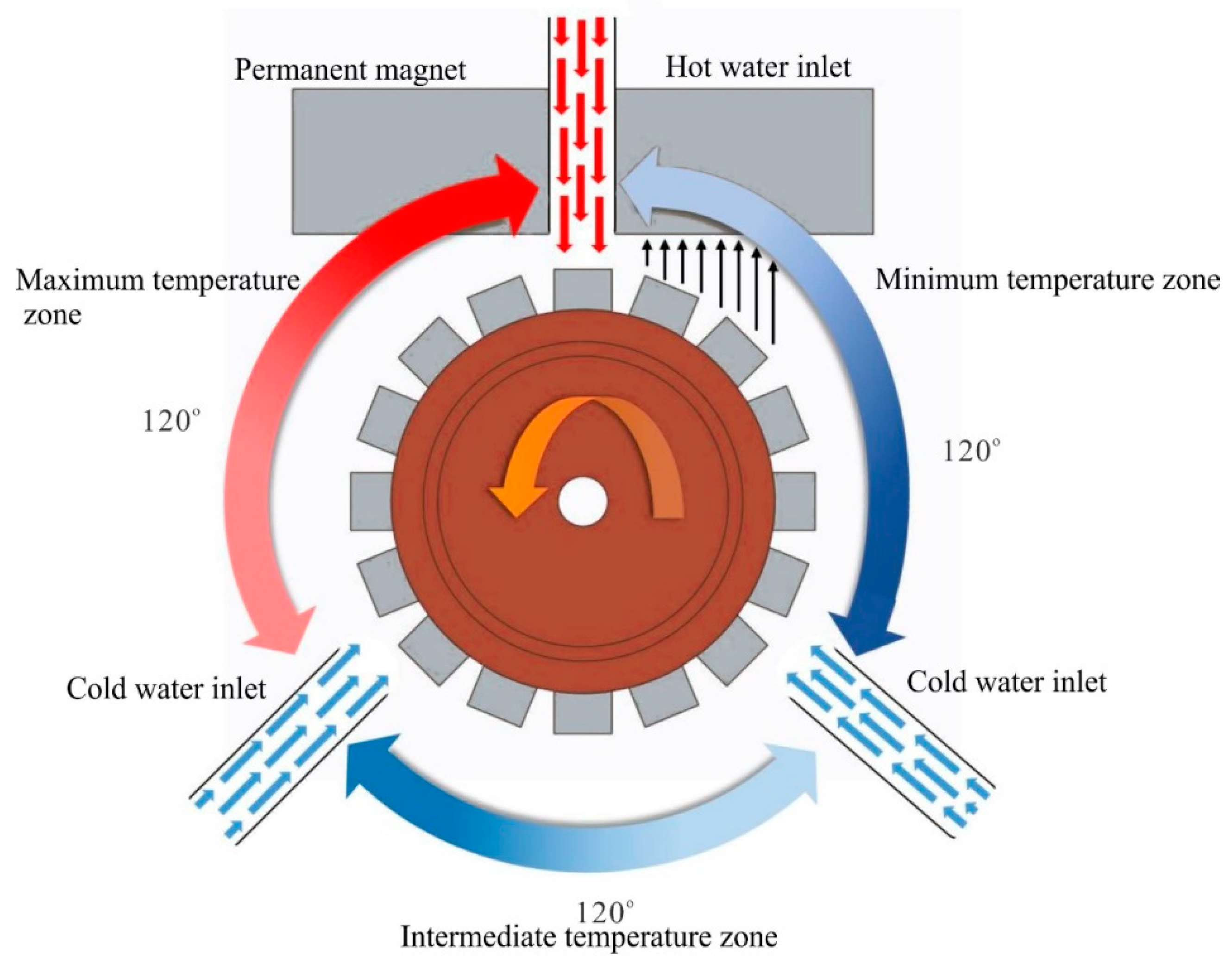
The thermomagnetic heat engine works due to the periodic alterations in the magnetic field of gadolinium, whose Curie temperature is around 293 K. Above this temperature, it behaves as a paramagnetic material and below this temperature it is ferromagnetic. This means that if a temperature difference is created between the gadolinium blocks near a permanent magnet, motion in linear or rotational form can be driven due to the difference in magnetic forces. This is the basic principle upon which the presented thermomagnetic heat engine works.
Figure 1 provides a schematic diagram of a thermomagnetic heat engine. A hot water inlet is installed to create a difference in temperature between blocks, which are essential components of the heat engine. The gadolinium blocks in the high temperature zone are paramagnetic and experience no magnetic forces from the permanent magnet. On the other hand, the blocks in the low temperature zone are ferromagnetic and experience magnetic forces from the permanent magnet. The difference in forces result in a net torque on the gadolinium rotor and results in rotation. As the blocks in the close vicinity of the rotor are continuously replaced, the rotor undergoes steady and continuous rotation.
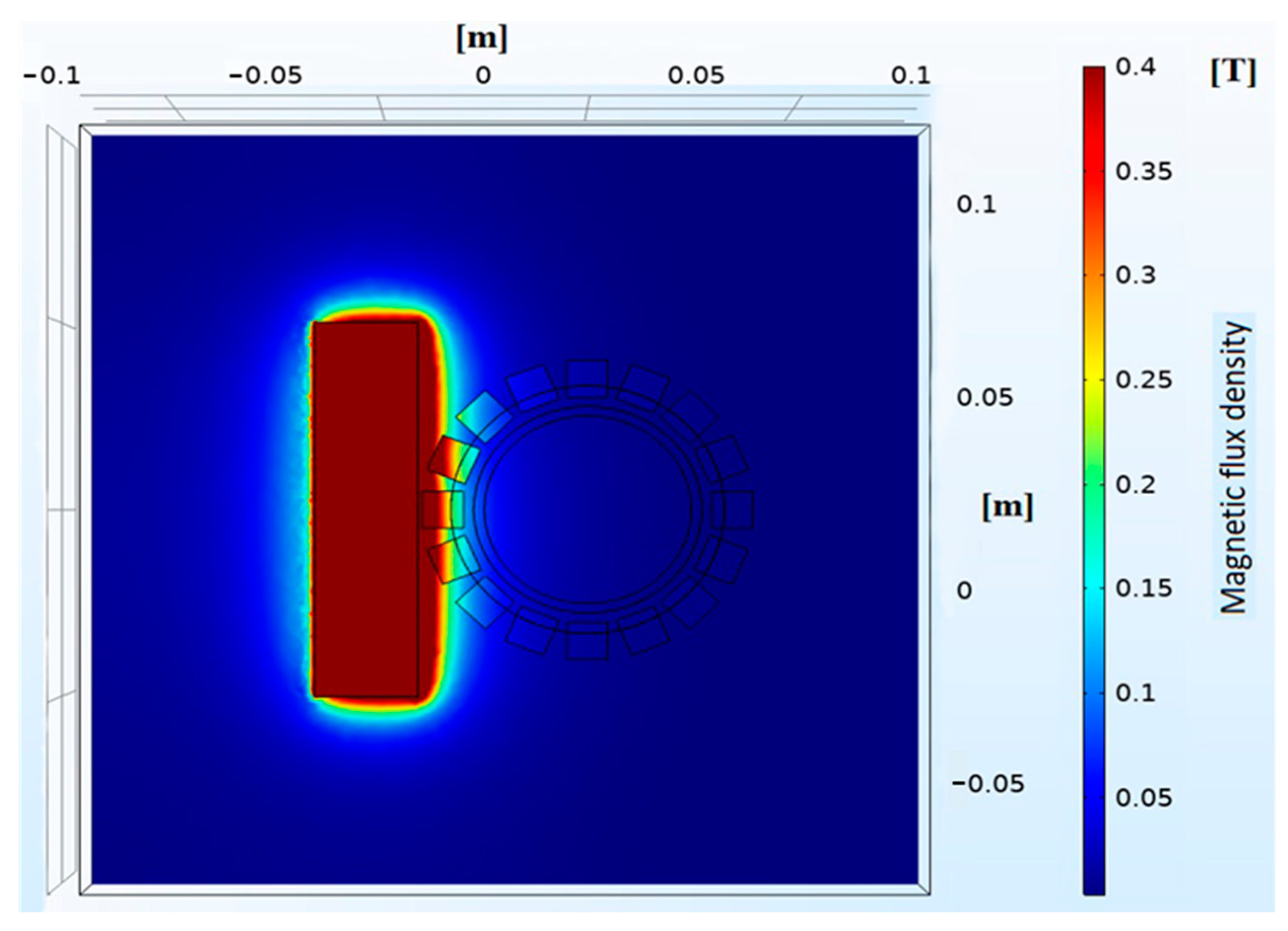
This rotary design of a thermomagnetic heat engine has been studied with simulation tools, such as COMSOL. A 3D model of the geometry is prepared and studied with different permeability properties for different components of the engine. The distribution of magnetic field lines on the gadolinium rotor is given in
Figure 2. Here, the permeability of gadolinium on the right side of the permanent magnet is higher compared to the left side. As a result, the magnetic flux density penetrating the blocks on the right side of the rotor is higher compared to the left side. This will create a net imbalance of force, which will result in rotation of the rotor.
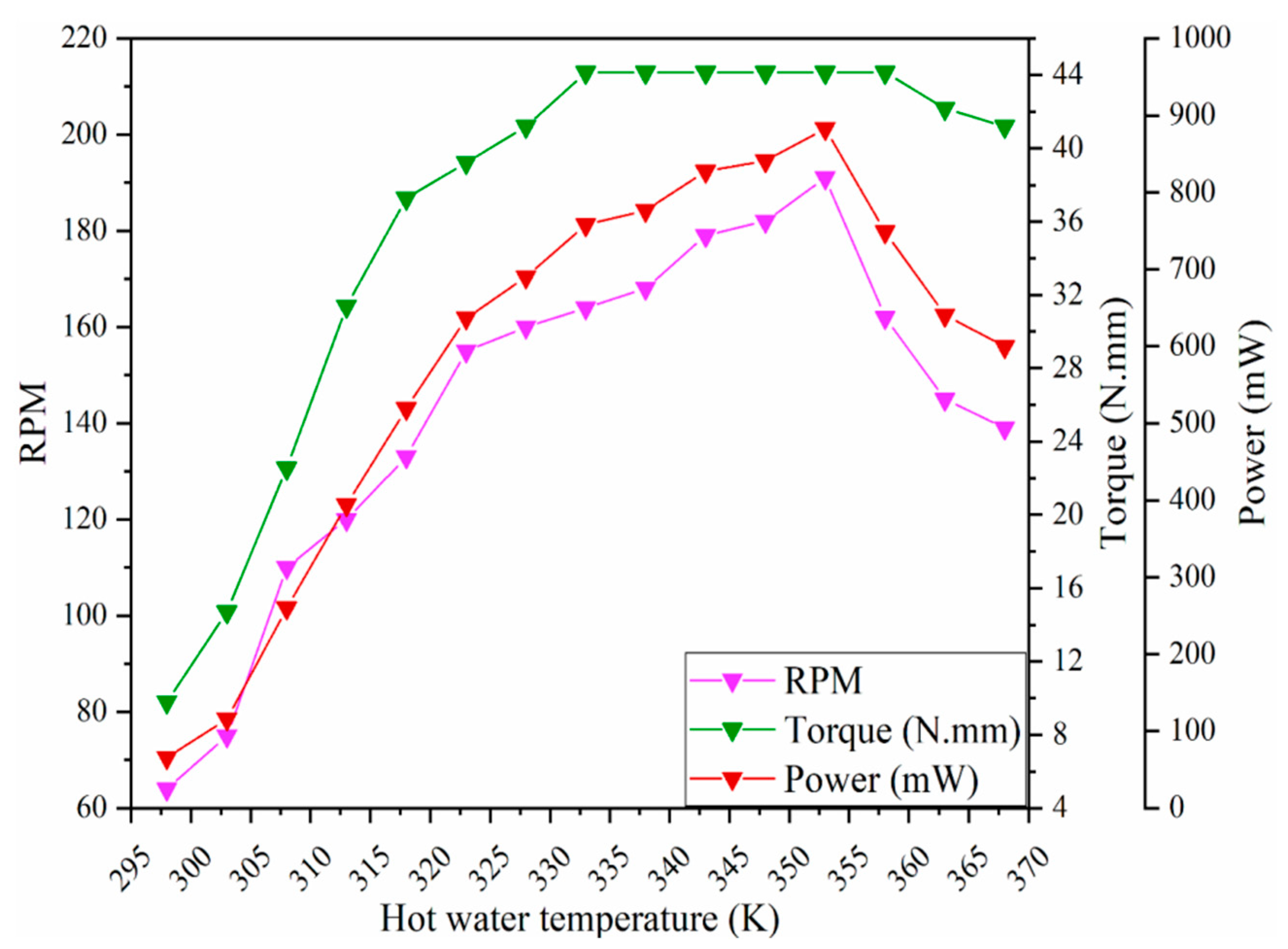
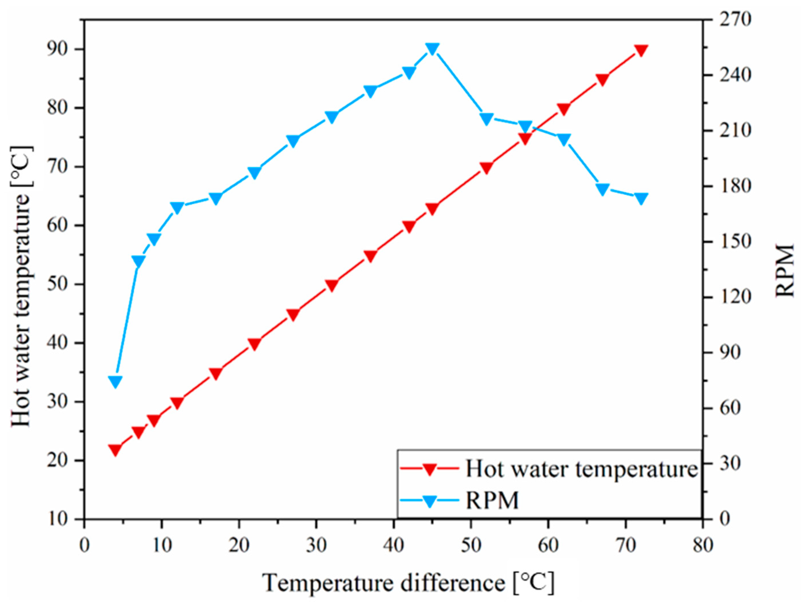
The rotations per minute produced by the engine are directly proportional to the temperature of the hot water. As the temperature of hot water increases, the difference in forces between the gadolinium blocks in the vicinity of the permanent magnet also increases. This results in stronger forces of attraction and hence higher rpm and torque.
Figure 3 shows how the hot water temperature is related to a number of key performance parameters of the heat engine.
3. Design and Fabrication of a Thermomagnetic Heat Engine
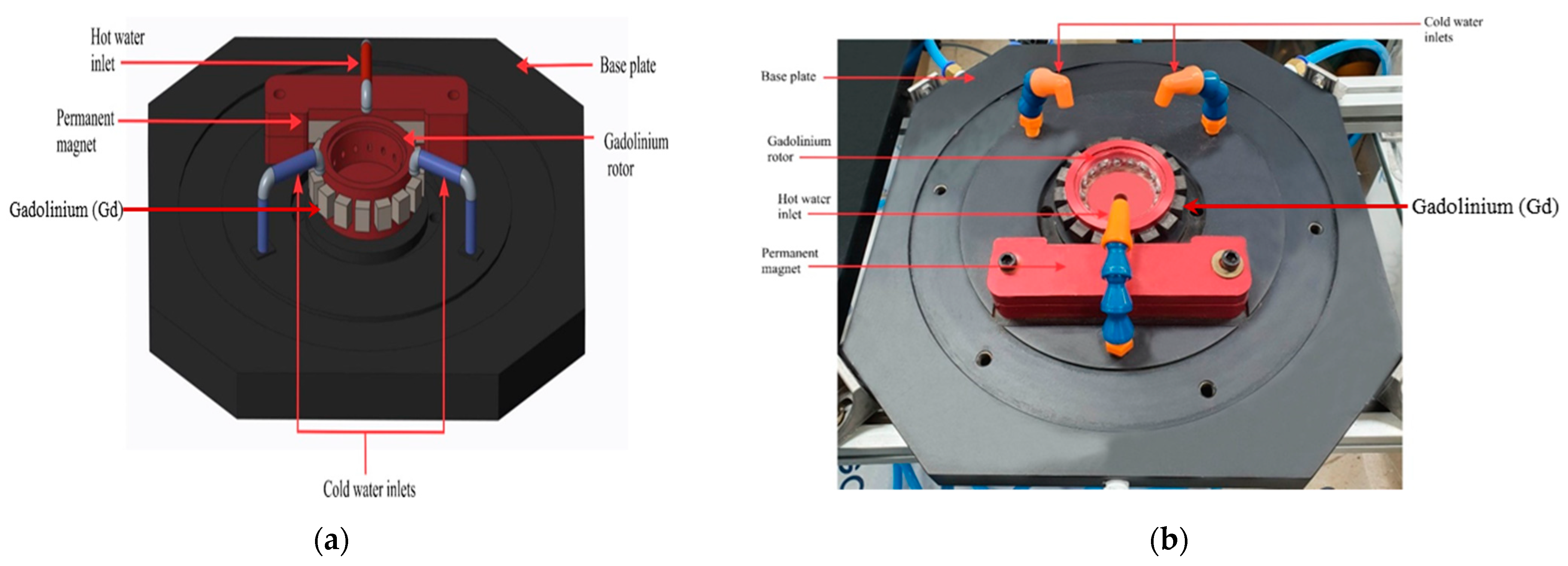
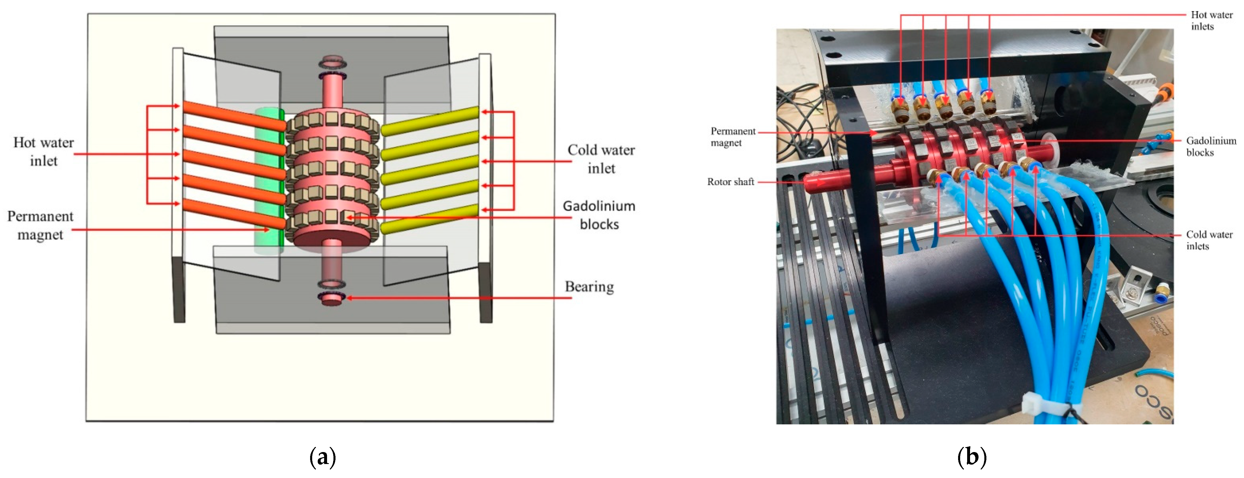
Figure 4 gives a 3D schematic and an actually built thermomagnetic heat engine. The major components of the system are as follows: an aluminum base plate, three water inlets, a magnet housing to hold the permanent magnet, and the gadolinium rotor. The rotor is fixed on the base plate with a bearing and has 16 gadolinium blocks attached to it. The gadolinium blocks have dimensions of 1 cm × 1 cm × 1 cm and are firmly attached to the rotor with screws. Holes are placed at adequate positions in the base plate and in the center of the rotor for adequate drainage of water during its operation. The water inlets are connected with a pump that can maintain any specified water flow rate.
The thermomagnetic heat engine can be scaled up to increase the total output. One of the ways this can be achieved is by connecting several rotors in series on a shaft and then extracting the rotational mechanical energy through a single shaft.
Figure 5 presents a schematic and fabricated scaled-up model of the thermomagnetic heat engine, which has the shape of a circular cylinder. This heat engine has five gadolinium rotors attached to a single shaft. Each rotor has 16 gadolinium blocks, and thus there is a total of 80 blocks in the system. For the inputs, each rotor is given a heat source and a heat sink in the form of hot and cold water inlets. There are a total of five cold and five hot water inlets in the system. This heat engine follows the same principle and the goal is to create an imbalance of forces near the permanent magnet. Hence, the permanent magnet is installed next to the hot water inlet. In this manner, a temperature difference is successfully created between the blocks near the magnet and this results in rotation of the rotors.
4. Application of Electric Generators: EMG, TENG
Two different types of electric generators were tested in conjunction with the operation of the thermomagnetic heat engine producing rotational kinetic energy converted from low temperature thermal energy. An electromagnetic generator (EMG) and a triboelectric nanogenerator (TENG) were experimented from the perspective of maximum electricity production, where both generators were operated simultaneously as they were connected in series with the thermomagnetic heat engine. Here, two different configurations were considered in combining the EMG and the TENG, which feature a difference in transmitting the rotational motion delivered by the thermomagnetic heat engine.
4.1. Hybridized EMG and TENG (Horizontal Configuration)
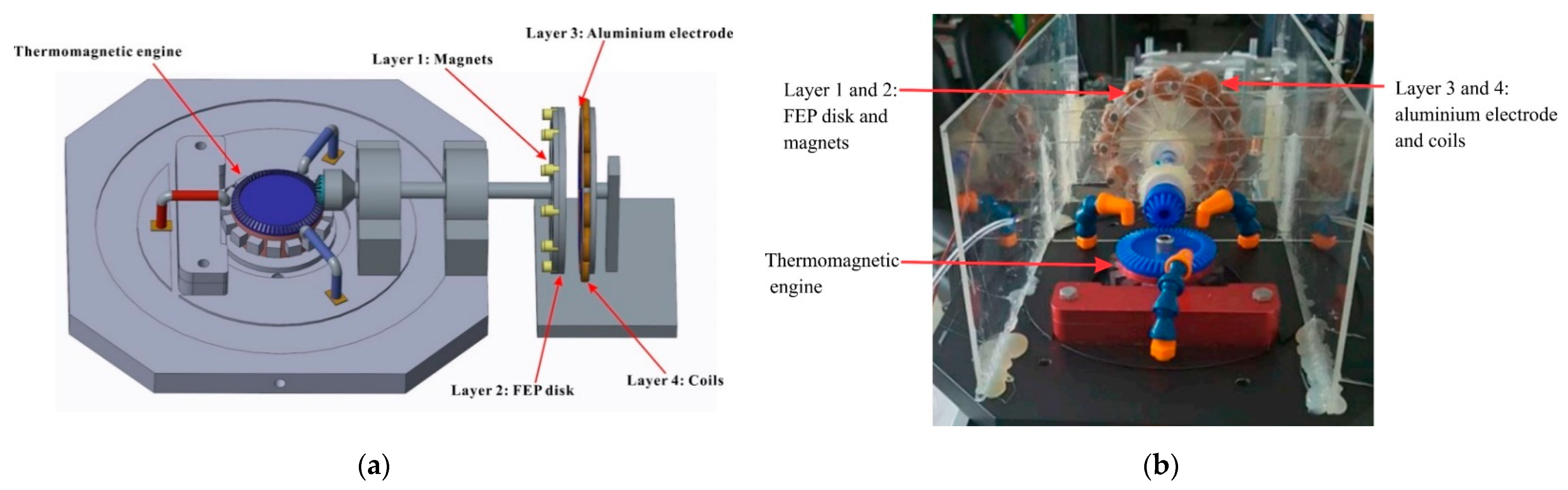
Figure 6 presents a schematic and fabricated model of a hybridized TENG and EMG generator. In this design the thermomagnetic heat engine is combined with the TENG and EMG generators through a beveled gear mechanism. The beveled gear mechanism changes the axis of rotation of the generator by 90°; thus providing a firm support to the rotating components while increasing the RPM of the rotating components of the generator. The gear ratio of the primary gear to the secondary gear is 3:1, which results in a considerable increase in RPM.
A disk-shaped TENG is used here, where the stator are the aluminum electrodes attached at a fixed distance from the rotating FEP disk. The distance between the components of the TENG is 1.2 mm during its operation. The two components of the EMG, the coils and the magnets, are attached to the stator and rotor of the TENG, respectively. The distance between these two components is held constant at 2.5 mm during its rotation.
4.2. Hybridized EMG with TENG (Vertical Configuration)
Different from the above generator using the beveled gear mechanism, a combined generator comprising a triboelectric nanogenerator and an electromagnetic generator is placed in the same direction of axial rotation with the thermomagnetic heat engine.
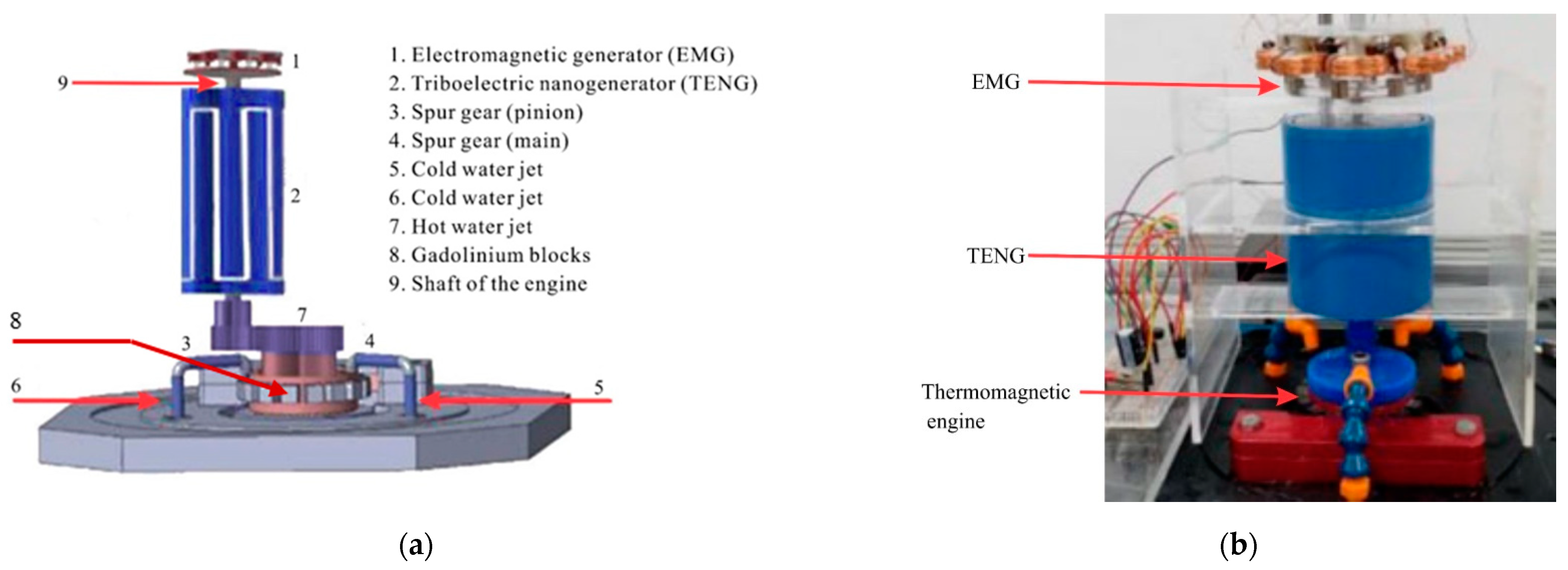
Figure 7 shows a schematic and fabricated model of the hybridized EMG/TENG generator.
The base is the same engine as described earlier in
Section 2 and
Section 3. To connect the engine with the hybrid generator, a gear mechanism is used. The gear ratio between the primary gear and pinion is 3:1 and it results in an overall increase in the output rpm. The importance of this increase will become clear with results discussed later as the output electrical power is greatly enhanced with the increased rpm.
The triboelectric nanogenerator has two major components: an outer hollow stator made from aluminum and an inner rotor made from FEP. The rotor of the TENG is made from 15 strips of charge carrier FEP film, each with a thickness of 100 µm. The stator is made of aluminum with 15 bar shaped electrode pairs. The rotor rotates at a distance of 1 mm away from the stator. A single shaft runs through the center of the geometry of the rotor. This connects with the thermomagnetic heat engine through a pinion at the bottom and the rotating part of the EMG is also connected at the same disk. The rotating part of the EMG comprises a disk with magnets attached on its periphery. The magnets have alternating north and south poles, as in a standard EMG. Finally, at the top is the stator of the EMG, which is located at a distance of 2 mm from the magnets.
5. Results and Discussion
To measure the performance parameters for different configurations of the generators, the hot water temperature was gradually increased from 35 °C to 85 °C and values of RPM and mechanical power were recorded at regular intervals.
A key phenomenon that was observed with the mechanical output for different configurations (of the generators) was a decrease in performance after increasing the hot water temperature beyond a certain critical point. This might arise from the limited amount of heat transfer interaction between the heat engine and water jets (hot and cold) as the rotation of the thermomagnetic engine was produced by the difference in permeability of the hot and cold gadolinium blocks. Once the temperature of the hot water jet is increased beyond a certain critical point, the cold water jets were not able to adequately reduce the temperature of the blocks, which require cooling. This results in a higher value of permeability for the blocks and an overall difference in the permeability between the hot side and cold side blocks decreases. As a result, increasing the temperature of the hot water jet further lowers the mechanical performance of the heat engine. This critical point roughly occurs at a temperature difference of 45 °C between the hot and cold jets.
5.1. Cylindrical Thermomagnetic Heat Engine
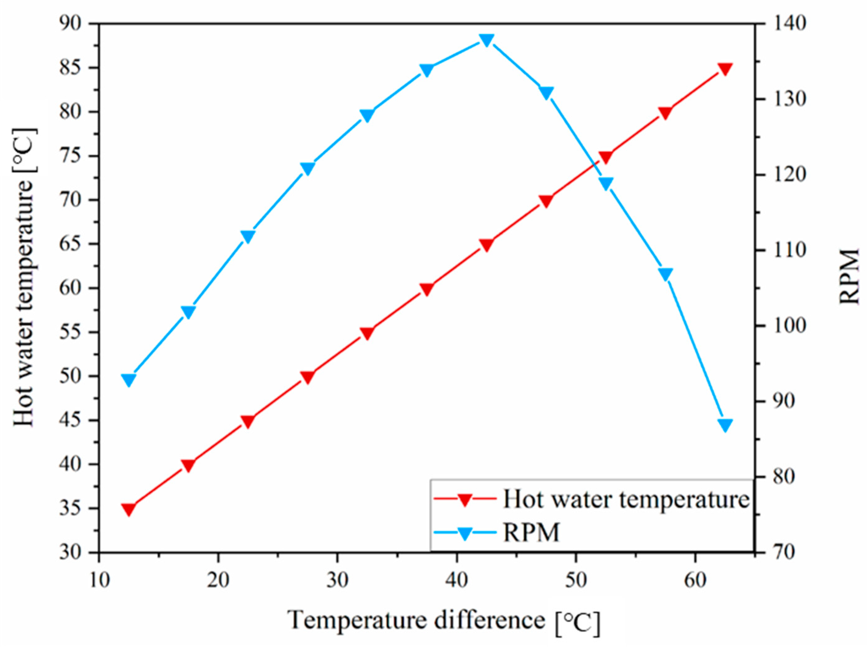
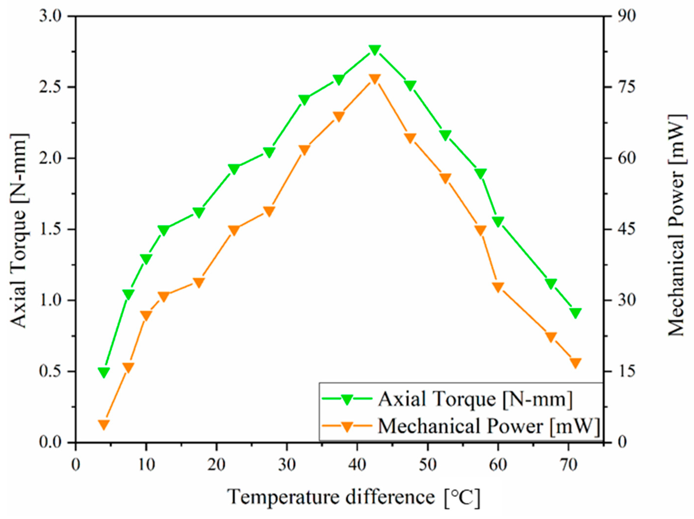
Figure 8 and
Figure 9 give the relation between the temperature difference of the jets and the mechanical output parameters of the scaled-up thermomagnetic heat engine in a circular cylindrical shape. The engine produced much higher mechanical power as compared to the original engine, as shown in
Figure 4. The cold water temperature in these measurements was 22.5 °C, and the maximum power output was measured with a hot water temperature of 65 °C. The output can be further increased at lower hot water temperature by either decreasing the cold water temperature or by enhancing the heat transfer properties of the gadolinium blocks. As shown in
Figure 9, this engine provided a much higher mechanical output of 1.1 W as five gadolinium rotors were connected in series.
5.2. Results for Hybridized EMG/TENG (Horizontal Configuration)
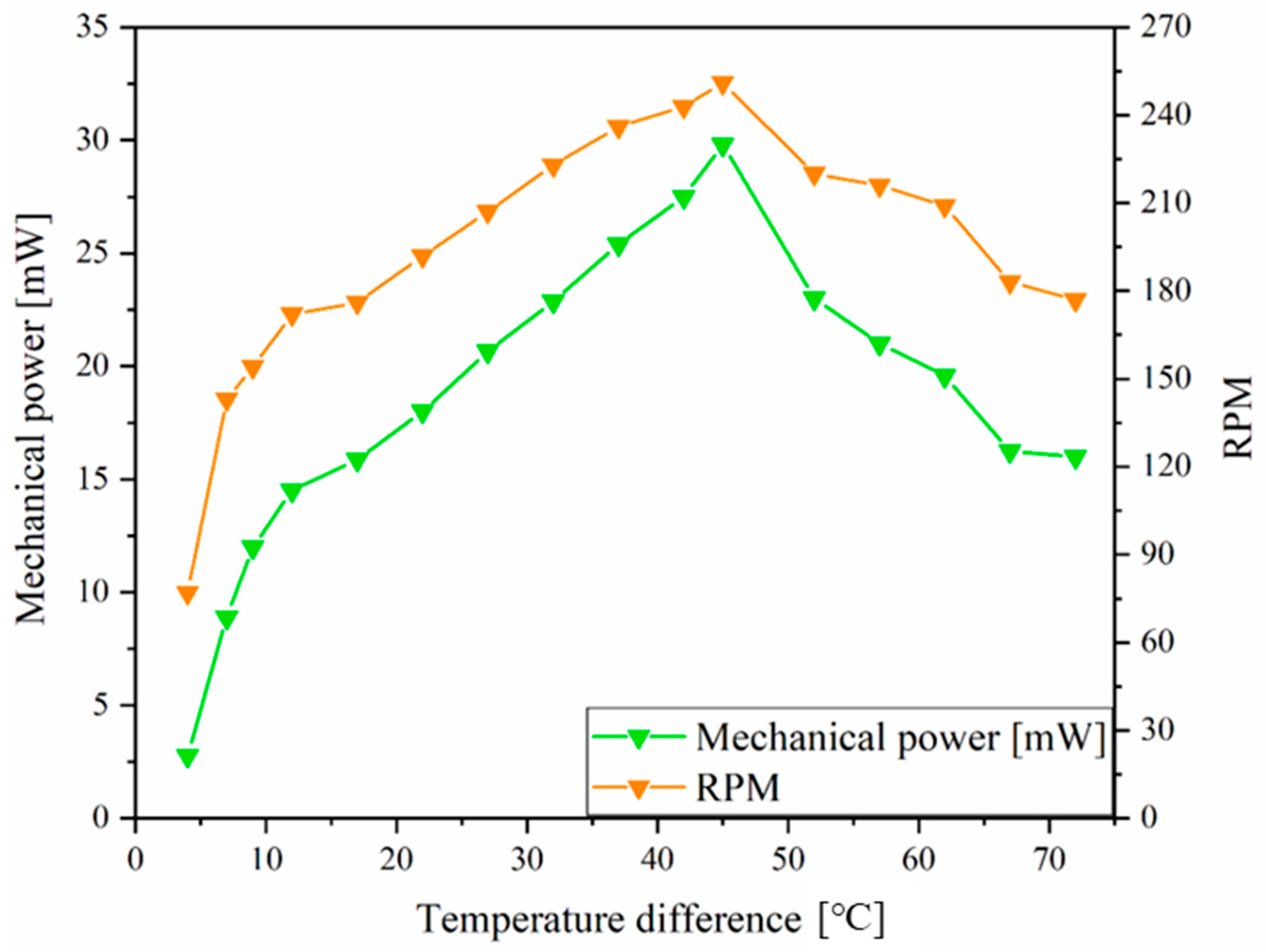
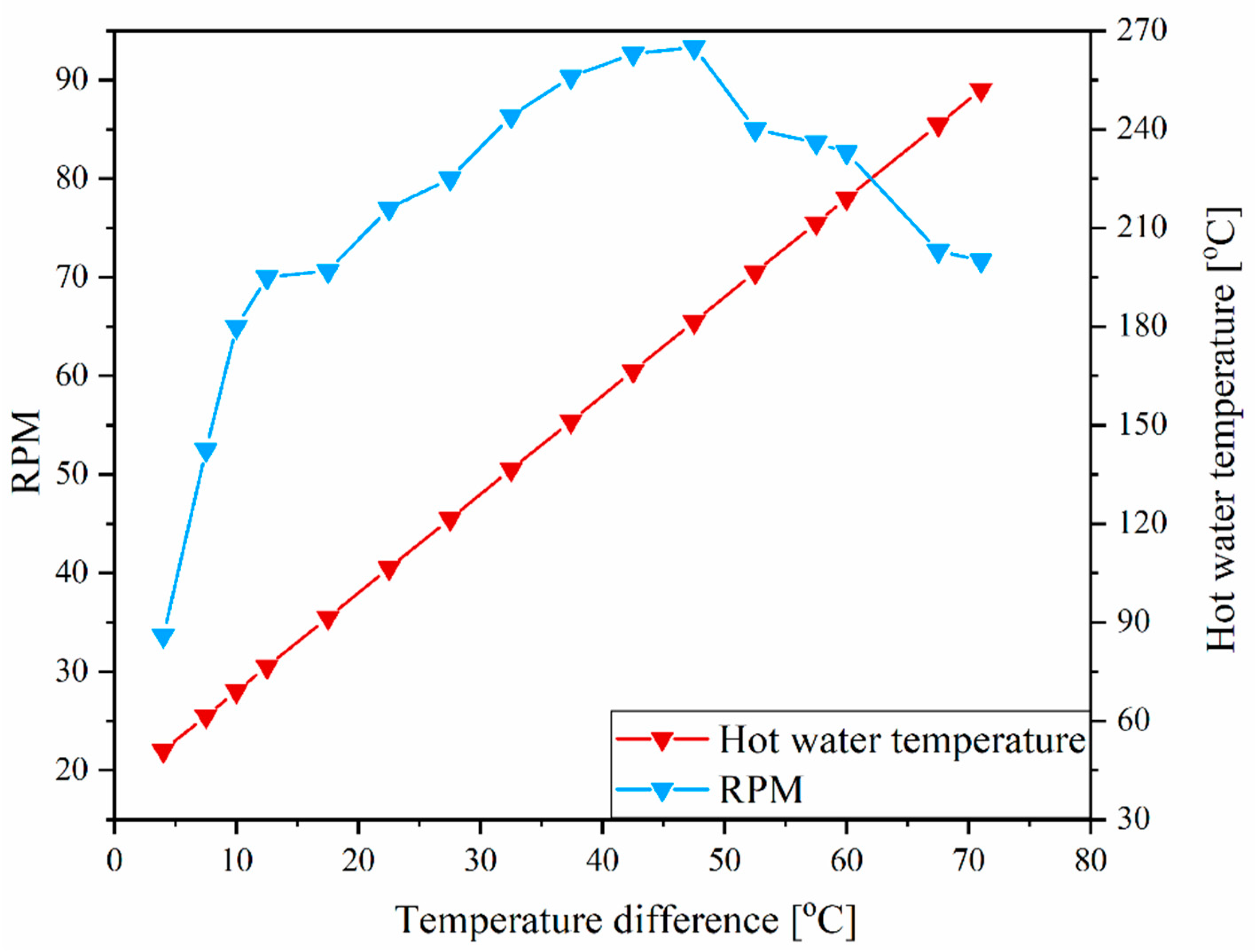
Figure 10 and
Figure 11 give the relation between hot water temperature, RPM, and the mechanical output (mW) of the thermomagnetic heat engine. The maximum mechanical output obtained from the engine is 29.5 mW at a temperature difference of 45 °C between the hot and cold water jets. It also produces the highest RPM of 250 at this temperature.
Modulation to about 10 kΩ was performed for the matched resistance as the EMG and TENG were connected to the transformers. As shown in
Figure 12, the hybridized EMG/TENG was capable of producing the maximum electric power output of 0.75 mW with a loading resistance of 10 kΩ.
5.3. Hybridized EMG/TENG (Vertical Configuration)
Figure 13 and
Figure 14 give the mechanical output parameters for the vertical configuration of the hybridized TENG and EMG generator. The generator was able to produce the maximum output when the temperature difference between the hot and cold water jets was 45 °C. Throughout the experiment, the temperature of the cold water jet was maintained at a constant value of 18.5 °C.
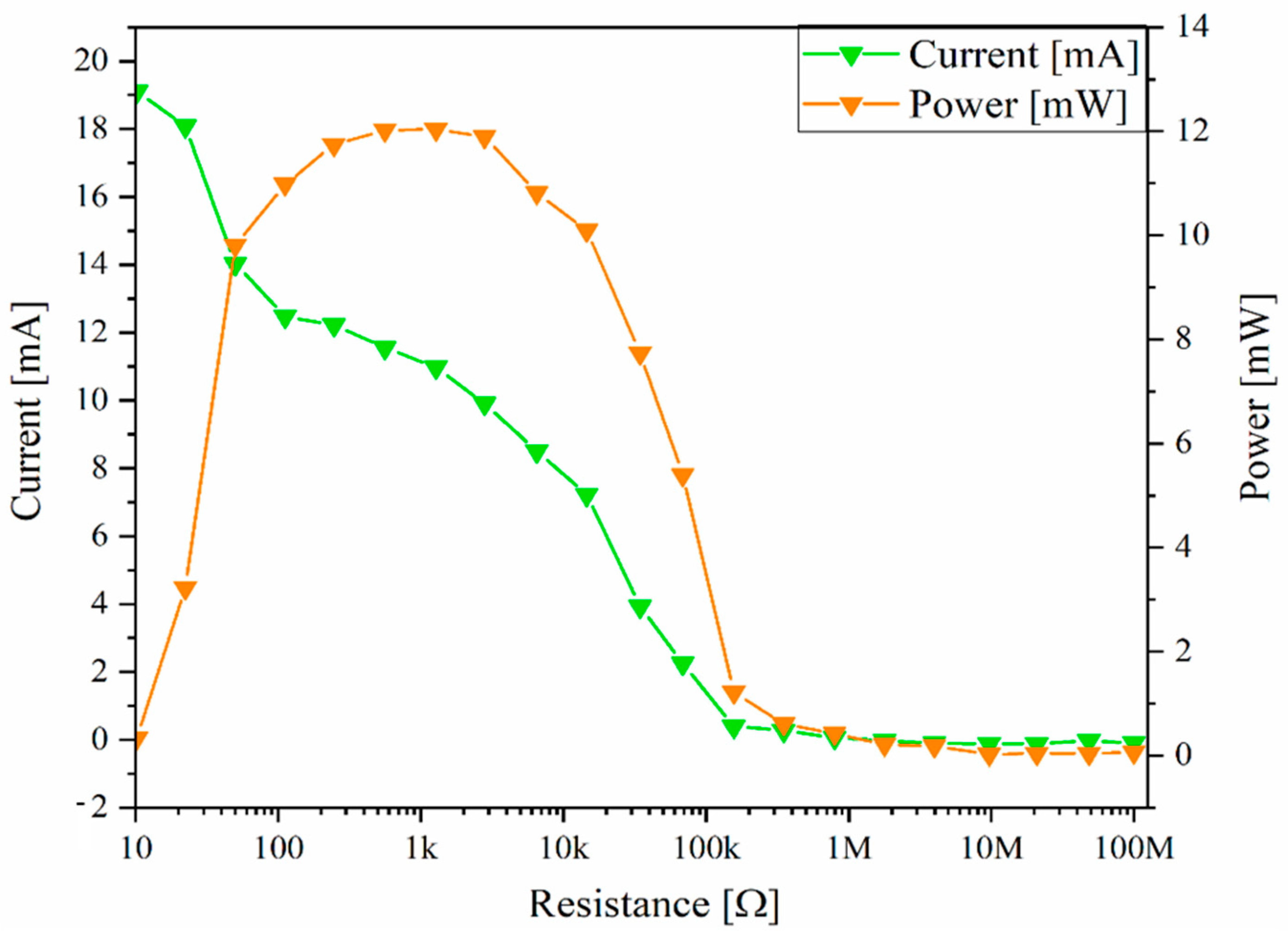
Figure 15 presents the total DC power output of the hybridized EMG/TENG under various loading conditions. As shown, it reached the maximum value of 12.1 mW when a load resistance of 120 Ω was measured.


