
Maximizing Energy Efficiency in Hybrid Overlay-Underlay Cognitive Radio Networks Based on Energy Harvesting-Cooperative Spectrum Sensing


Abstract
:
1. Introduction
- In order to improve the double waste of energy and frequency band caused by centralized cooperative spectrum sensing, we introduce distributed cooperative spectrum sensing based on energy-correlation. Each PUs has a fixed SUs cluster in each time slot to sense the state of the master user, so as to reduce the energy consumption of SUs sensing.
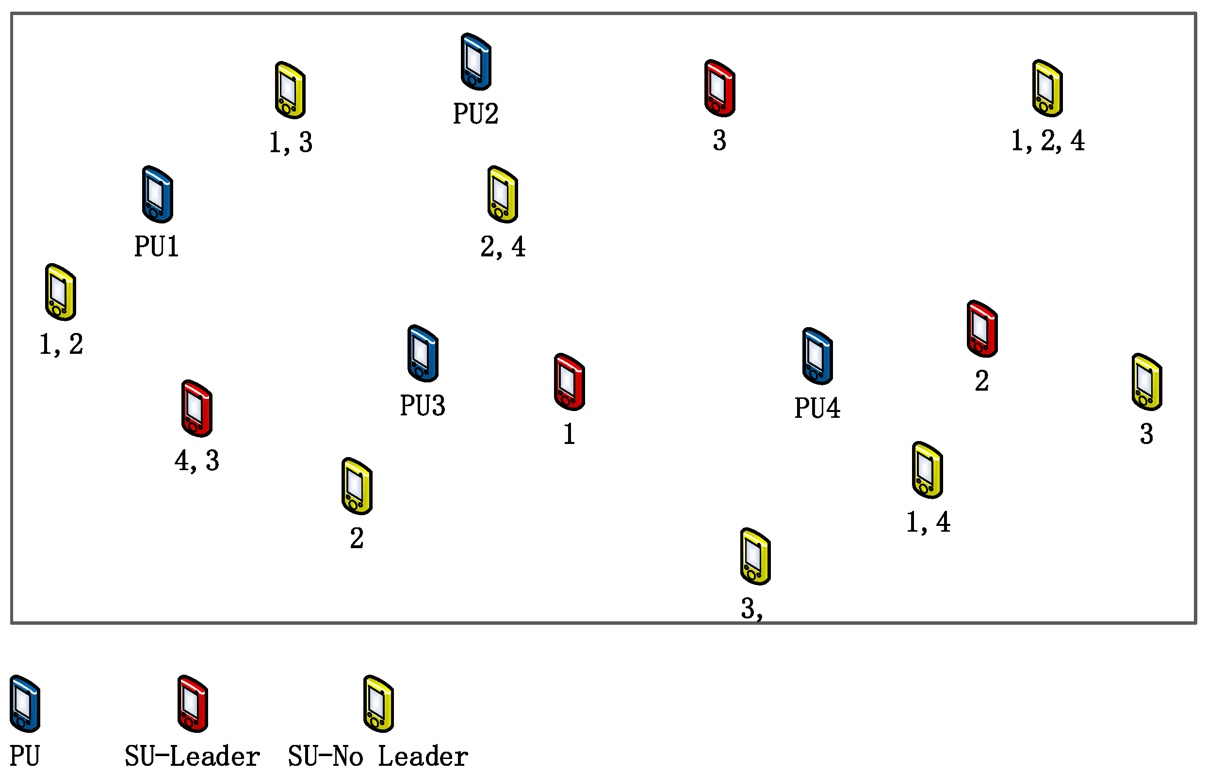
- We improve the energy-based cooperative user selection algorithm and propose an energy-based multi-band multi-user selection scheme, where we first formulate an optimization problem to select a leader for each channel. Then we formulate another optimization problem to select the corresponding cooperative SU.
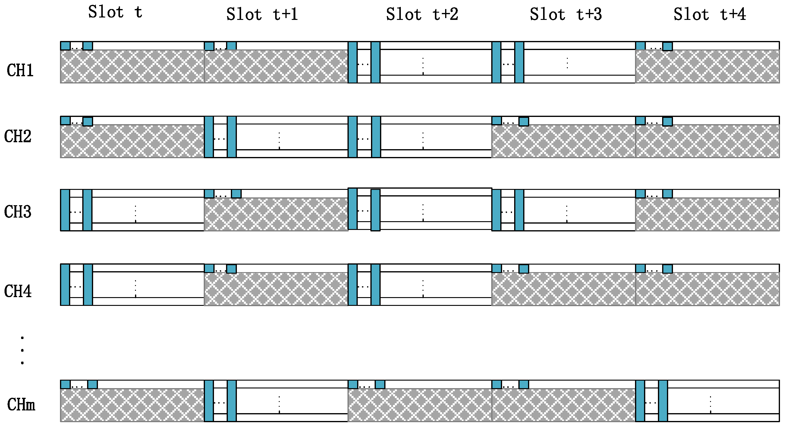
- Through energy-based distributed cooperative spectrum sensing, the sensing time is effectively reduced, and more time slots are allocated to SUs.
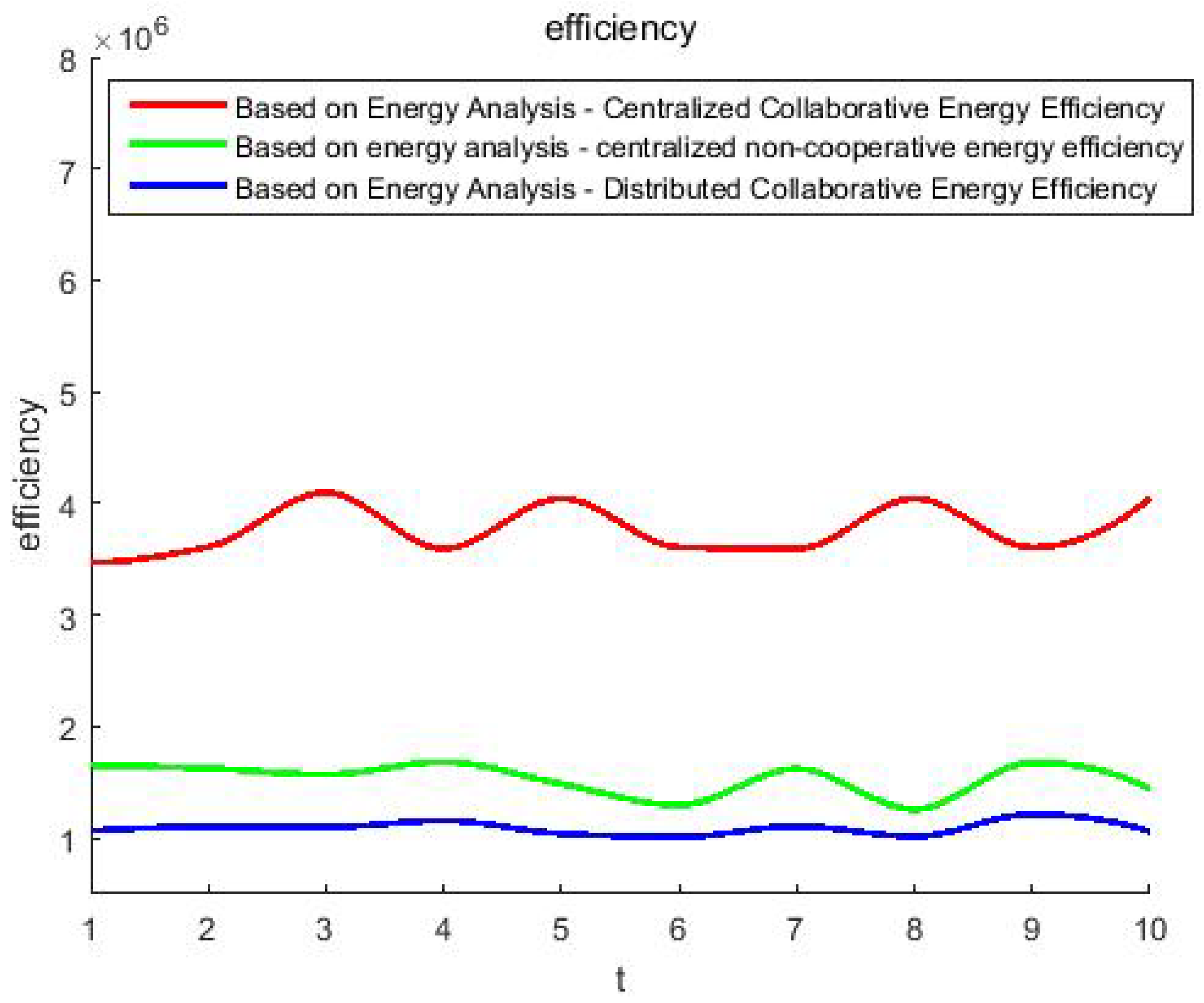
- Simulation results show that our proposed scheme is significantly better than the centralized scheme in terms of SUs access capability and energy efficiency.
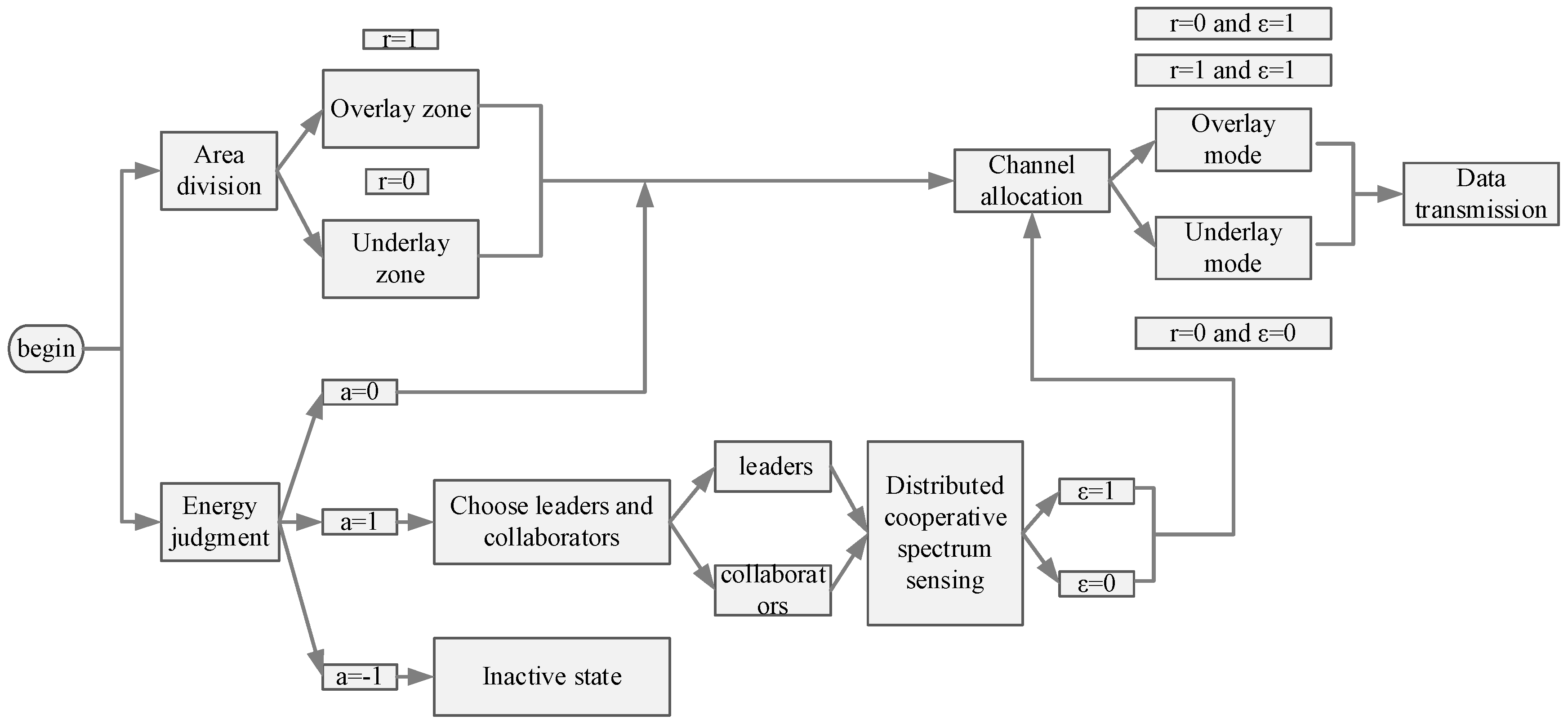
2. System Model
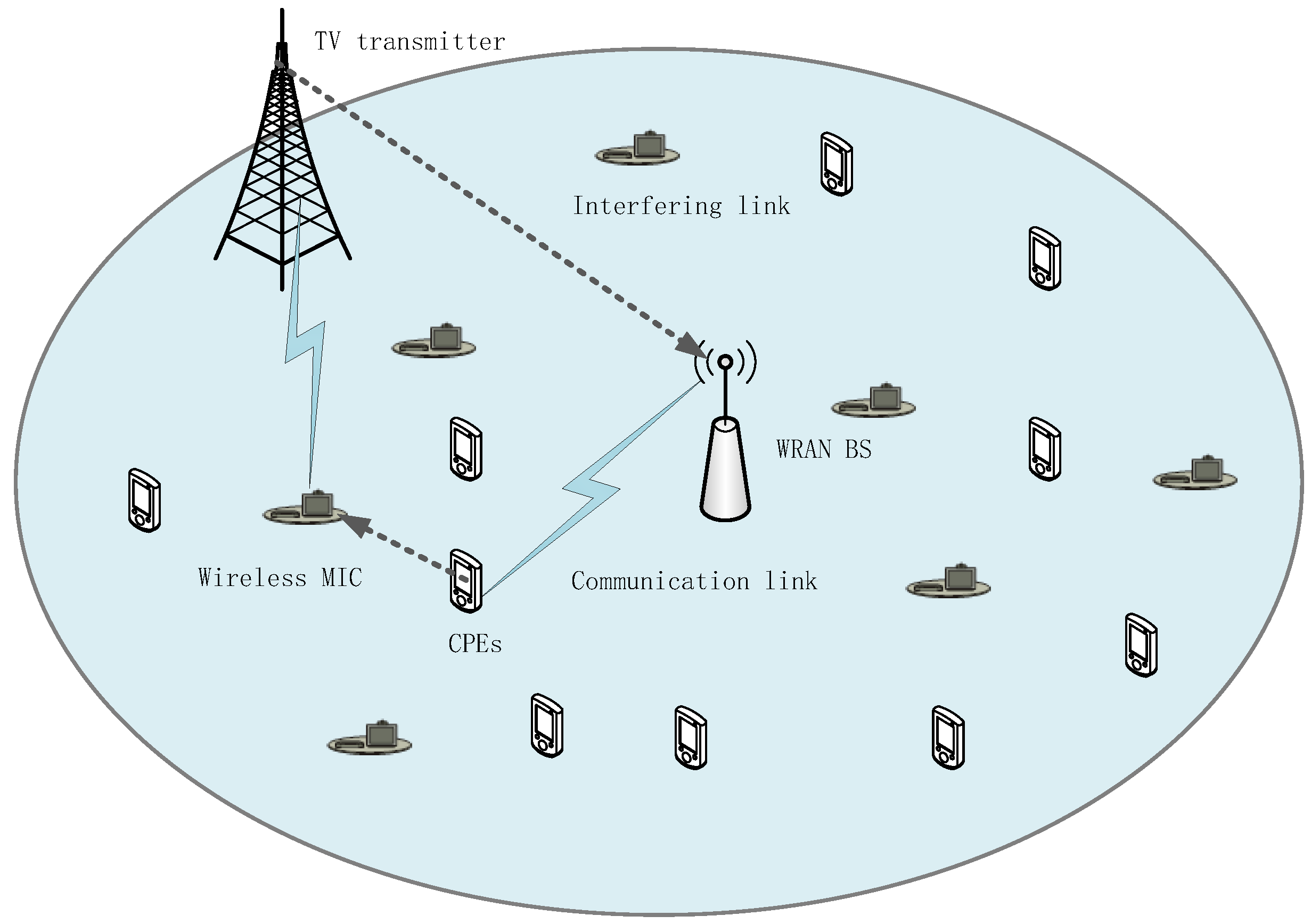
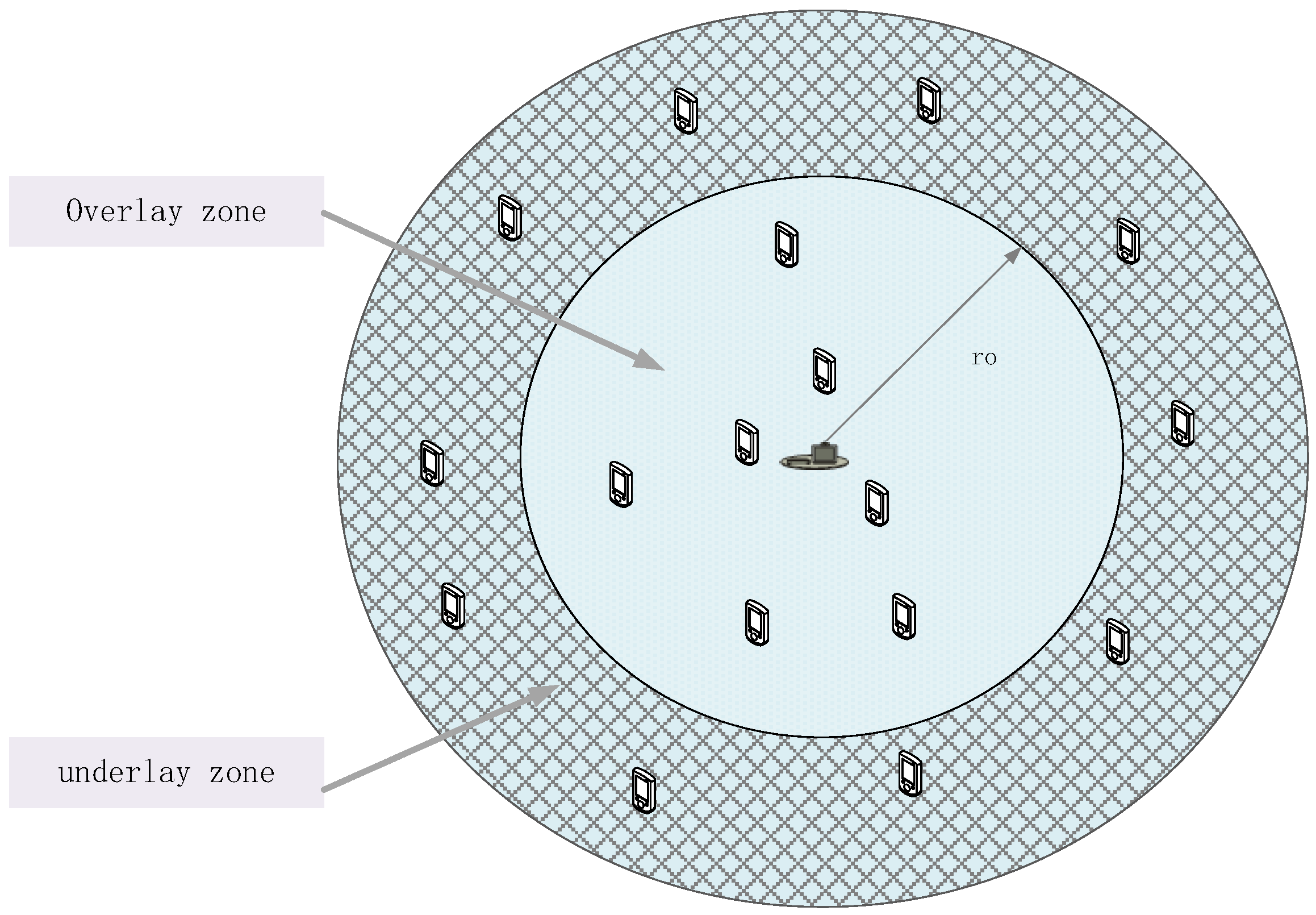
2.1. Network Model
2.2. Distributed Energy Harvesting Model
2.3. Distributed Cooperative Spectrum Sensing
| Algorithm 1 Based on Energy-Distributed User Selection (n) |
| 1. Begin
2. int , , , with all values set to zero, t = 0, , , , T, , , , , SNRij, SNRavg 3.for int t = 0 to T do 4. for int j = 1 to n do 5. 6. 7. if 8. 9. else if 10. 11. else 12. 13. end for 14. if 15. 16. else 17. 18. end for 19. end for 20. for int I = 1 to m do 21. for int j= 1 to n do 22. if 23. using formula (9), find the optimal solution through the branch-and-bound (B&B) algorithm. 24. renturn 25. using formula (14), find the optimal solution through the branch-and-bound (B&B) algorithm. 26. renturn 27. end for 28. end for 29. end for 30. t = t + 1 31.end |
2.4. Distributed Channel Assignment
| Algorithm 2 Distributed Channel Allocation Algorithm |
| 1. Begin
2. int y [n] with all values set to zero, , r, T, , td, ,, t = 1, s = 0 3. Calculate and , using (15) and (16). 4.for int t = 1 to T do 5. for int j = 1 to m do 6. for int i = 1 to n do 7. if or 8. s = s + 1 9. end 10. 11. for C = 1 to c do 12. 13. select R with maximum value in SUs 14. set selected and delete i from SUs 15. end 16. end 17. end 18. t = t + 1 19.end |
3. Energy Efficiency Optimization Based on Energy Judgment-Distributed Cooperative Sensing
4. Simulation Results and Discussion
4.1. Simulation Parameter Settings
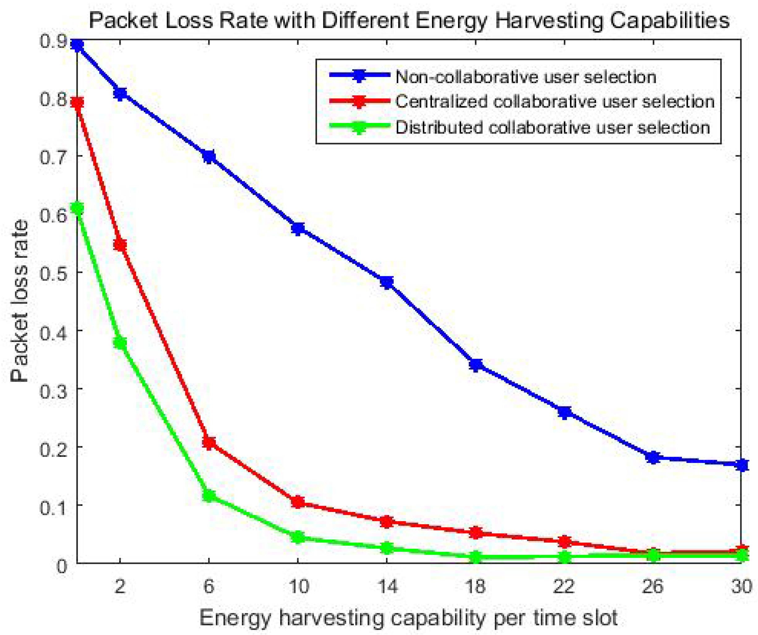
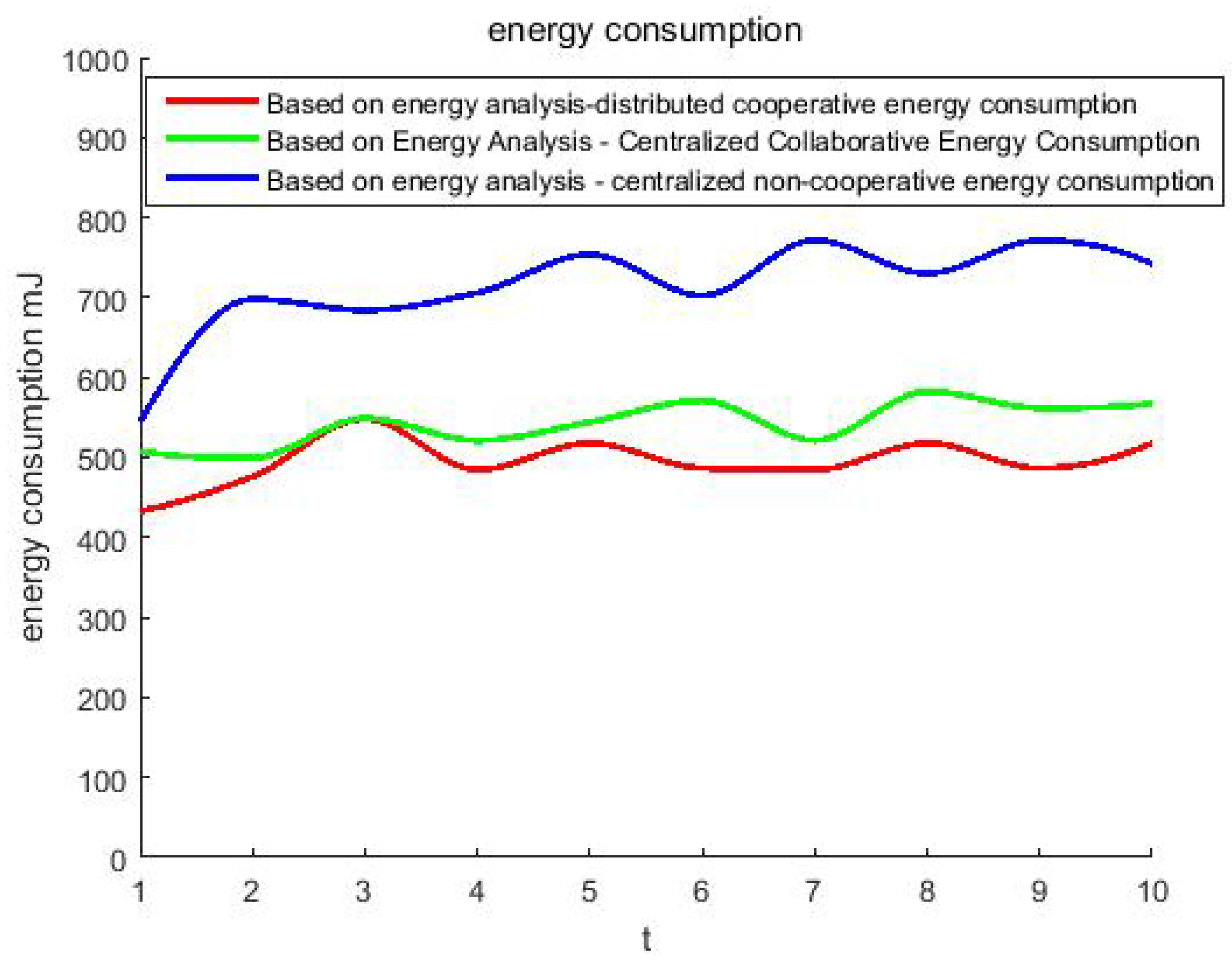
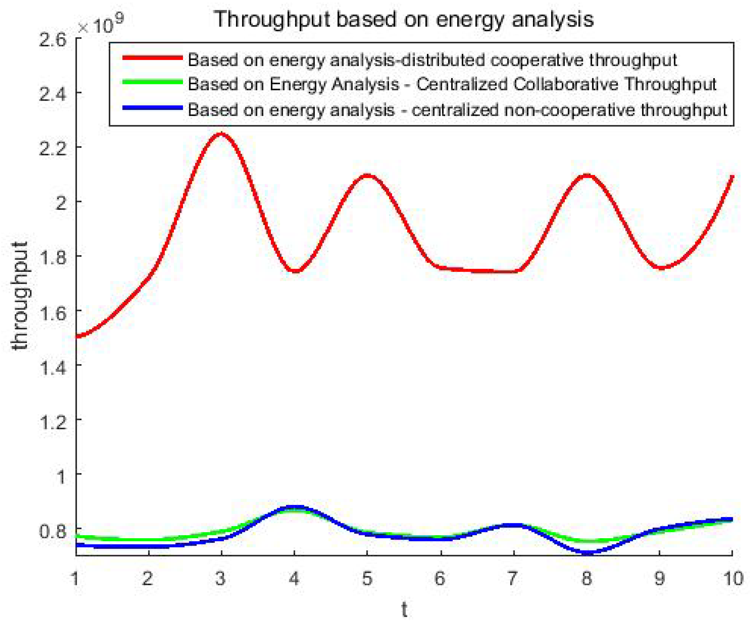
4.2. Discussion of Simulation Results
5. Conclusions
Author Contributions
Funding
Institutional Review Board Statement
Informed Consent Statement
Data Availability Statement
Conflicts of Interest
References
- Kolodzy, P.; Avoidance, I. Spectrum POLICY Task Force; Rep. ET Docket; Federal Communications Commission: Washington, DC, USA, 2002; Volume 40, pp. 147–158. [Google Scholar]
- Xiao, Y.; Krunz, M.; Shu, T. Multi-operator network sharing for massive IoT. IEEE Commun. Mag. 2019, 57, 96–101. [Google Scholar] [CrossRef] [Green Version]
- Abbas, G.; Abbas, Z.H.; Tanveer, M.; Ullah, S.; Naushad, A. HBLP: A hybrid underlay-interweave mode CRN for the future 5G-based Internet of Things. IEEE Access 2020, 8, 63403–63420. [Google Scholar]
- Liu, Z.; Ding, G.; Wang, Z.; Zheng, S.; Sun, J.; Wu, Q. Cooperative Topology Sensing of Wireless Networks with Distributed Sensors. IEEE Trans. Cogn. Commun. Netw. 2020, 7, 524–540. [Google Scholar] [CrossRef]
- Hsieh, S.H.; Liang, W.J.; Lu, C.S.; Pei, S.C. Distributed compressive sensing: Performance analysis with diverse signal ensembles. IEEE Trans. Signal Process. 2020, 68, 3500–3514. [Google Scholar] [CrossRef] [Green Version]
- Ansere, J.A.; Han, G.; Wang, H.; Choi, C.; Wu, C. A Reliable energy efficient dynamic spectrum sensing for cognitive radio IoT networks. IEEE Internet Things J. 2019, 6, 6748–6759. [Google Scholar] [CrossRef]
- Altinel, D.; Kurt, G.K. Modeling of multiple energy sources for hybrid energy harvesting IoT systems. IEEE Internet Things J. 2019, 6, 10846–10854. [Google Scholar] [CrossRef]
- Cai, L.X.; Liu, Y.; Luan, T.H.; Shen, X.S.; Mark, J.W.; Poor, H.V. Sustainability analysis and resource management for wireless mesh networks with renewable energy supplies. IEEE J. Sel. Areas Commun. 2014, 32, 345–355. [Google Scholar] [CrossRef] [Green Version]
- Ni, L.; Da, X.; Hu, H.; Zhang, M.; Cumanan, K. Outage constrained robust secrecy energy efficiency maximization for EH cognitive radio networks. IEEE Wirel. Commun. Lett. 2019, 9, 363–366. [Google Scholar] [CrossRef] [Green Version]
- Gupta, I.; Sahu, O.P. An Overview of primary user emulation attack in cognitive radio networks. In Proceedings of the 2018 Second International Conference on Computing Methodologies and Communication (ICCMC), Erode, India, 15–16 February 2018; pp. 27–31. [Google Scholar]
- Sarikhani, R.; Keynia, F. Cooperative spectrum sensing meets machine learning: Deep reinforcement learning approach. IEEE Commun. Lett. 2020, 24, 1459–1462. [Google Scholar] [CrossRef]
- Huang, H.; Mu, J.; Jing, X. Cooperative spectrum sensing based on centralized double threshold in mcn. China Commun. 2020, 17, 235–242. [Google Scholar] [CrossRef]
- Yan, J.; Liu, Y. A dynamic SWIPT approach for cooperative cognitive radio networks. IEEE Trans. Veh. Technol. 2017, 66, 11122–11136. [Google Scholar] [CrossRef]
- Lu, W.; Nan, T.; Gong, Y.; Qin, M.; Liu, X.; Xu, Z.; Na, Z. Joint resource allocation for wireless energy harvesting enabled cognitive sensor networks. IEEE Access 2018, 6, 22480–22488. [Google Scholar] [CrossRef]
- Zhang, W.; Wang, C.X.; Chen, D.; Xiong, H. Energy–spectral efficiency tradeoff in cognitive radio networks. IEEE Trans. Veh. Technol. 2015, 65, 2208–2218. [Google Scholar] [CrossRef]
- Zheng, K.; Liu, X.; Zhu, Y.; Chi, K.; Liu, K. Total throughput maximization of cooperative cognitive radio networks with energy harvesting. IEEE Trans. Wirel. Commun. 2019, 19, 533–546. [Google Scholar] [CrossRef]
- Olawole, A.A.; Takawira, F.; Oyerinde, O.O. Cooperative spectrum sensing in multichannel cognitive radio networks with energy harvesting. IEEE Access 2019, 7, 84784–84802. [Google Scholar] [CrossRef]
- Gupta, N.; Dhurandher, S.K.; Sehgal, A. A contract theory approach-based scheme to encourage secondary users for cooperative sensing in cognitive radio networks. IEEE Syst. J. 2019, 14, 2400–2410. [Google Scholar] [CrossRef]
- Maji, P.; Yadav, K.; Roy, S.D.; Kundu, S. Secrecy and throughput performance of an energy harvesting hybrid cognitive radio network with spectrum sensing. Wirel. Netw. 2020, 26, 1301–1314. [Google Scholar] [CrossRef]
- Kumar, A.; Thakur, P.; Pandit, S.; Singh, G. Analysis of optimal threshold selection for spectrum sensing in a cognitive radio network: An energy detection approach. Wirel. Netw. 2019, 25, 3917–3931. [Google Scholar] [CrossRef]
- Liu, X.; Zheng, K.; Chi, K.; Zhu, Y.H. Cooperative spectrum sensing optimization in energy-harvesting cognitive radio networks. IEEE Trans. Wirel. Commun. 2020, 19, 7663–7676. [Google Scholar] [CrossRef]
- Al-Jarrah, M.A.; Al-Dweik, A.; Ikki, S.S.; Alsusa, E. Spectrum-occupancy aware cooperative spectrum sensing using adaptive detection. IEEE Syst. J. 2019, 14, 2225–2236. [Google Scholar] [CrossRef] [Green Version]
- Ding, J.; Jiang, L.; He, C. User-centric energy-efficient resource management for time switching wireless powered communications. IEEE Commun. Lett. 2017, 22, 165–168. [Google Scholar] [CrossRef]
- Yang, Z.; Xu, W.; Pan, Y.; Pan, C.; Chen, M. Energy efficient resource allocation in machine-to-machine communications with multiple access and energy harvesting for IoT. IEEE Internet Things J. 2017, 5, 229–245. [Google Scholar] [CrossRef]
- Azarhava, H.; Niya, J.M. Energy efficient resource allocation in wireless energy harvesting sensor networks. IEEE Wirel. Commun. Lett. 2020, 9, 1000–1003. [Google Scholar] [CrossRef]
- Zheng, K.; Liu, X.Y.; Liu, X.; Zhu, Y. Hybrid overlay-underlay cognitive radio networks with energy harvesting. IEEE Trans. Commun. 2019, 67, 4669–4682. [Google Scholar] [CrossRef]
- Karaca, H.M. Throughput optimization of multichannel allocation mechanism under interference constraint for hybrid overlay/underlay cognitive radio networks with energy harvesting. Electronics 2020, 9, 330. [Google Scholar] [CrossRef] [Green Version]
- Gharib, A.; Ejaz, W.; Ibnkahla, M. Enhanced multiband multiuser cooperative spectrum sensing for distributed CRNs. IEEE Trans. Cogn. Commun. Netw. 2019, 6, 256–270. [Google Scholar] [CrossRef]
- Cao, Y.; Pan, H. Energy-efficient cooperative spectrum sensing strategy for cognitive wireless sensor networks based on particle swarm optimization. IEEE Access 2020, 8, 214707–214715. [Google Scholar] [CrossRef]
- Gao, H.; Ejaz, W.; Jo, M. Cooperative wireless energy harvesting and spectrum sharing in 5G networks. IEEE Access 2016, 4, 3647–3658. [Google Scholar] [CrossRef]


| Symbol | Name | Value |
|---|---|---|
| T | time slot duration | 1 ms |
| Sensing Duration | 0.002 ms | |
| Td | Transmission duration | 0.098 ms |
| E | initial energy | range of random values [0, max(E)] |
| Ps | sense power | 110 mW |
| Po | Overlay transmit power | 50 mW |
| Pu | Underlay transmit power | 30 mW |
| PT | Primary user’ s power | 1W |
| etr | Residual energy at the beginning of time slot t | mJ |
| A | Path-loss exponent | 0.75 |
| H | Harvesting conversion efficiency | 0.75 |
| SNR | Signal to interference plus noise ratio | dB |
| B | Bandwith | 8 MHZ |
Publisher’s Note: MDPI stays neutral with regard to jurisdictional claims in published maps and institutional affiliations. |
© 2022 by the authors. Licensee MDPI, Basel, Switzerland. This article is an open access article distributed under the terms and conditions of the Creative Commons Attribution (CC BY) license (https://creativecommons.org/licenses/by/4.0/).
Share and Cite
Liu, Y.; Qin, X.; Huang, Y.; Tang, L.; Fu, J. Maximizing Energy Efficiency in Hybrid Overlay-Underlay Cognitive Radio Networks Based on Energy Harvesting-Cooperative Spectrum Sensing. Energies 2022, 15, 2803. https://doi.org/10.3390/en15082803
Liu Y, Qin X, Huang Y, Tang L, Fu J. Maximizing Energy Efficiency in Hybrid Overlay-Underlay Cognitive Radio Networks Based on Energy Harvesting-Cooperative Spectrum Sensing. Energies. 2022; 15(8):2803. https://doi.org/10.3390/en15082803
Chicago/Turabian StyleLiu, Yan, Xizhong Qin, Yan Huang, Li Tang, and Jinjuan Fu. 2022. "Maximizing Energy Efficiency in Hybrid Overlay-Underlay Cognitive Radio Networks Based on Energy Harvesting-Cooperative Spectrum Sensing" Energies 15, no. 8: 2803. https://doi.org/10.3390/en15082803
APA StyleLiu, Y., Qin, X., Huang, Y., Tang, L., & Fu, J. (2022). Maximizing Energy Efficiency in Hybrid Overlay-Underlay Cognitive Radio Networks Based on Energy Harvesting-Cooperative Spectrum Sensing. Energies, 15(8), 2803. https://doi.org/10.3390/en15082803