1. Introduction
The conventional magnet wires used to make the windings of electrical machines are achieved using a polymeric insulation coating on the copper conductor called the enameled wire. The classic enameling process consists of applying very thin layers of polymeric varnish to the copper wire. The multipass process is used to obtain an increased diameter according to the specifications of international standards [
1,
2,
3].
The manufacturing process is well controlled. The viscosity of the varnish is optimized. When the wire passes through a felt applicator, it takes calibrated drops of varnish in the wire by the pressure of the varnish. It is calibrated in thickness by dies or by a metered deposit between felts. The copper conductor is then well centered with respect to the die. Dielectric tests [
4,
5] are carried out on standardized twisted specimens [
6] to check the wire characteristics, such as copper centricity.
The application of each layer by dies is followed directly by passing the wire through an enameling oven at 600 °C. The polymerization of the insulating layers is obtained by the actions of the heat and the solvents included in the initial varnish. These solvents represent approximately 60% of the varnish. They are classified as harmful and carcinogenic products. Every year in Europe, 40,000 tons of enamel varnishes are used, and 25,000 tons of solvents are eliminated into the air. Adding to this, due to the exothermic reaction of these solvents, 50,000 tons of CO
2 are generated [
7,
8].
The awareness of our societies to respect our environment makes it necessary to develop new manufacturing processes by extrusion that are less harmful and more economical [
1,
9]. The first results relative to electrical measurements suggest the use of the extruded coating wires [
9,
10]. One of the technological obstacles of these processes is mastering the centering of copper in its insulation. Indeed, the windings of electrical machines are made in such a way as to be able to create an electromagnetic field that allows the proper functioning of the machine. In the event of poor centering, the insulation will have thinner thicknesses in certain places. These will be vulnerable areas as the imposed electrical field is higher, which will lead to the premature appearance of partial discharges accelerating the aging of the insulation and leading to a premature fault [
11,
12,
13,
14,
15]. Therefore, the enameled wire concentricity is a parameter that intervenes in the lifespan of the windings of the electric machines.
The article proposes the study of a device for measuring the eccentricity of enameled wire on a continuous line. It exploits capacitance measurements to determine the thickness of the wire insulation. When the copper conductor is centered in the enamel, the insulation thickness should be the same all around and all along the enameled wire. Differential mode measurements compare the thicknesses by electrical measurements, which make it possible to deduce the centering of the enameled wire. This original method is noninvasive and can be operated without stopping the enameled wire production line and without any modification on the conductor and for all insulated varnishes. Only pulleys require special machining for each wire diameter. Finally, this device has advantages over the optical [
16,
17], magnetic [
17] or electromagnetic [
16] systems already used that cannot meet the needs of opaque or nanofilled varnishes and nonmagnetic wires, such as copper and aluminum.
2. Proposed Solution Principle
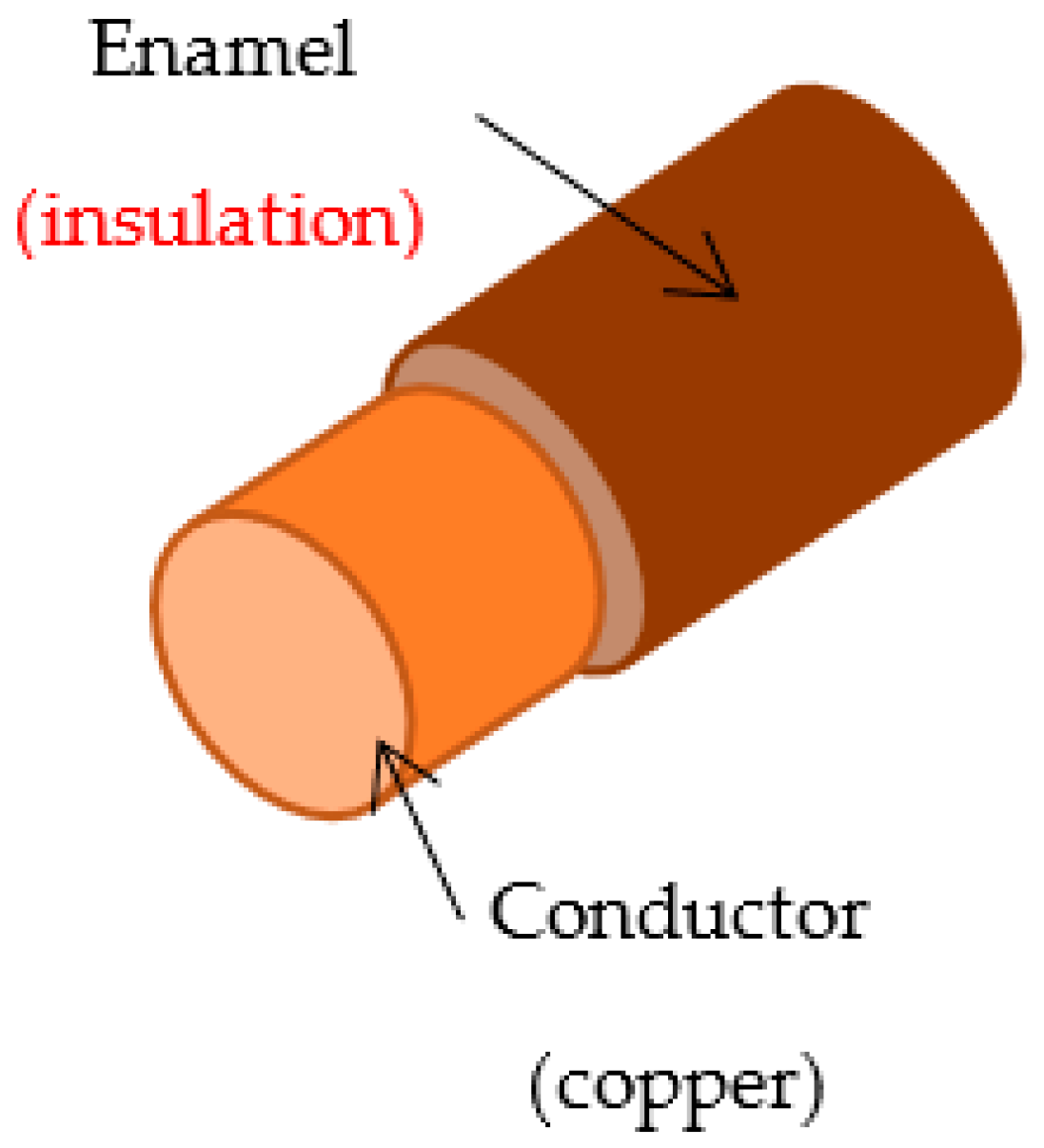
The proposed solution consists of verifying the eccentricity of the wire by an electrical measurement. Since this is a conductor with an insulator placed on it (
Figure 1), the idea is to form a capacitor and measure its capacitance.
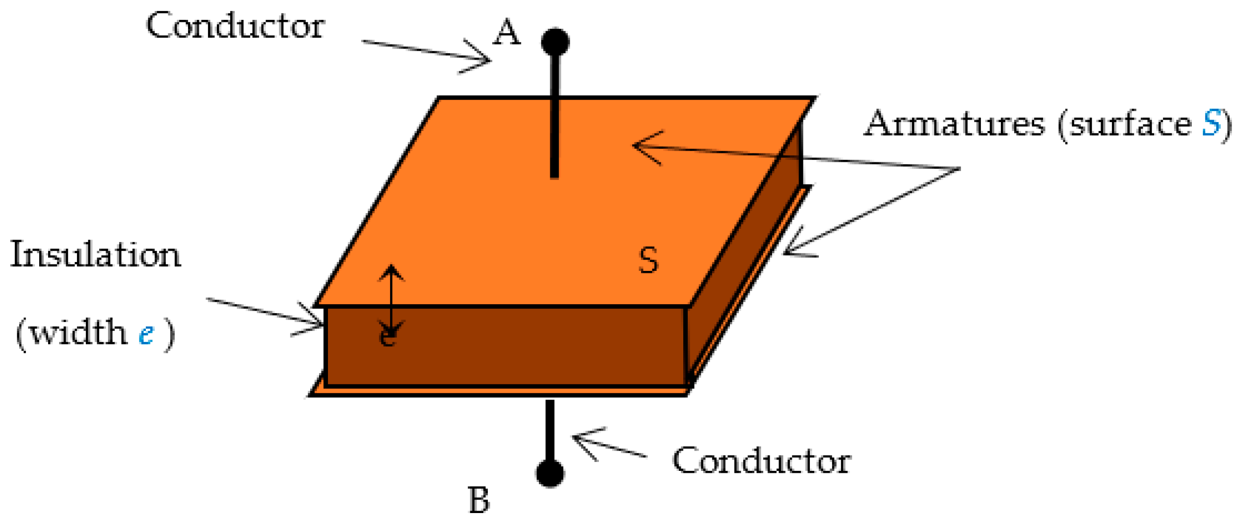
As a reminder, a capacitor is presented as two metal frames separated by an insulator (
Figure 2). It is, therefore, sufficient to add a second conductor (metal frame) on the insulation of the wire to form a capacitor.
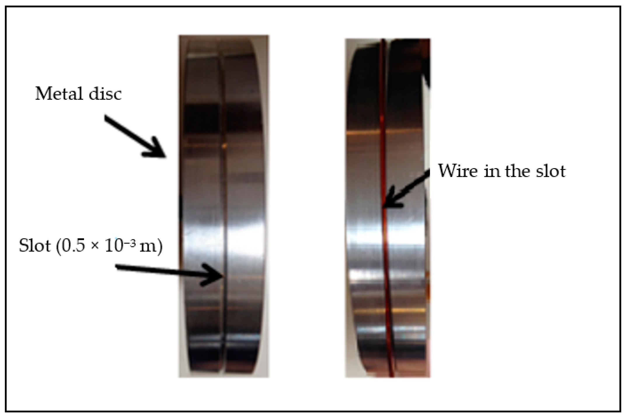
In order to respect the circular shape of the wire, a metal disc with a diameter of 0.1 m was used as the second reinforcement. On the outer edge, a circular slot with a radius of 0.5 × 10
−3 m was made so that it could contain the enameled wire (
Figure 3 and
Figure 4). This creates a cylindrical capacitor on the contact distance between the wire and the disc.
In the case of the cylindrical coaxial capacitor of length
l, the capacitance is given by the following [
18]:
with:
C: capacitance of the capacitor (F)
ɛ0: permittivity of the vacuum (8.854 × 10⁻¹² F·m−1)
ɛr: relative permittivity of the insulation (unitless)
R1: inner radius of the cylinder (m); this corresponds to the wire radius in this configuration
R2: outer radius of the cylinder (m)
e: Insulation thickness of the wire (m)
l: length of the cylinder (m); this is the arc formed by the contact between the disc and the wire
As only the longitudinal half of the cylinder is considered, half of the capacitance is determined. The relationship between the capacitance of the capacitor and the thickness of the dielectric in this case is given by the following equation:
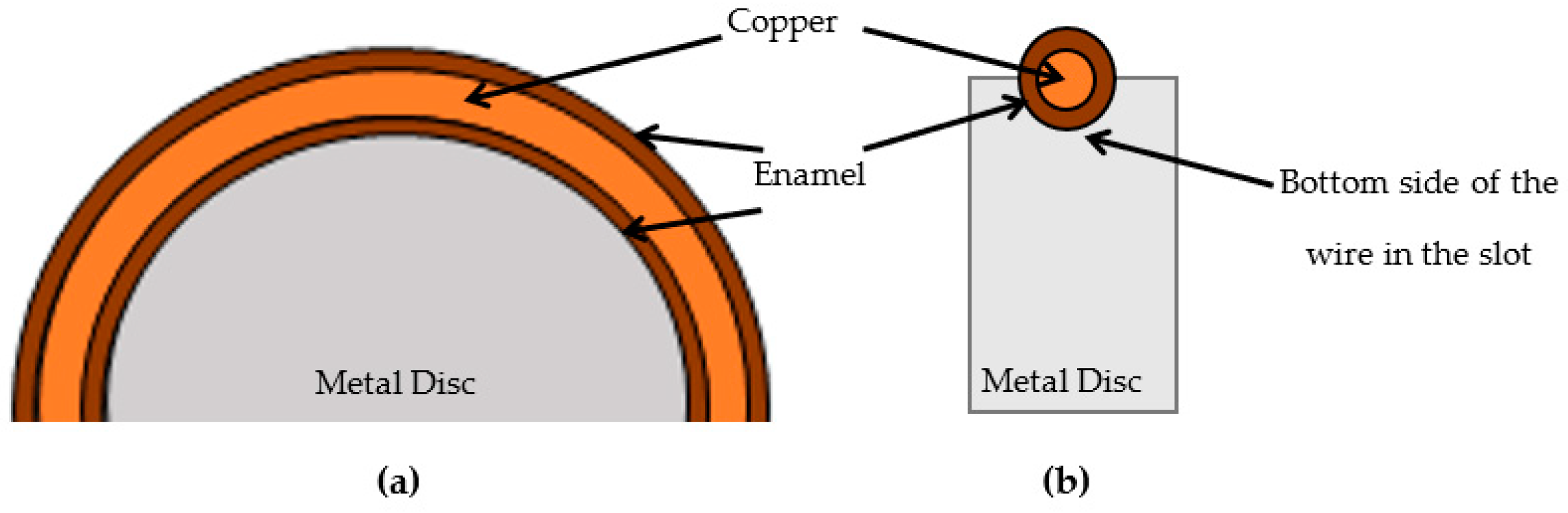
As the wire has a diameter of 0.95 × 10
−3 m, the enamel thickness is about 35 × 10
−6 m and the slot in the disc has a diameter of 10
−3 m, so the contact will only be made on half of the circumference of the wire (
Figure 4b).
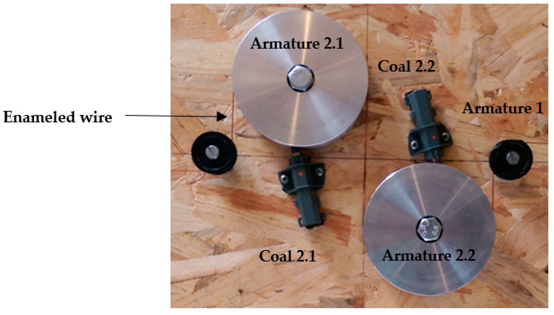
To find out if the conductor is centered on both sides of the wire, two disks are used (
Figure 5) to form two capacitors using the two halves of the wire circumference (top and bottom sides). This makes it possible to compare the thicknesses of the insulation on both sides of the wire, from the values of the capacities of the two capacitors.
The two coals will serve as contact for the two armatures, for each capacitor, and the contacts of the armature 1 will be recovered by clamps fixed on the stripped wire (without insulation).
3. Experimental Setup
3.1. Description
The measuring device model consists of two parts. The first consists of creating a capacitor between a pulley and the conductor of the enameled wire (
Figure 5). Two capacitors at opposite sides of the wire are achieved. The measurement of their capacitance will be carried out by an electronic card used as the second part (
Figure 6). It converts differential capacitances in a proportional voltage signal.
Knowing that the capacitance is inversely proportional to the thickness of the dielectric (Equation (1)), it is possible to know the insulator thickness modification by the capacitance monitoring measurement. To make this measurement, an electronic circuit that can include the capacitor and provide a varying quantity according to its capacitance was best suited. The diagram in
Figure 7 shows the process of this measurement for two sides of the wire.
Firstly, an integrated circuit for precision timing NE555 is used as an astable multivibrator mode for the two capacitors of our device. The principle of this circuit is to provide a rectangular signal with a frequency that varies according to the passive components (resistors and capacitors) added to it.
To compare the two thicknesses, it suffices to compare the two frequencies. However, the comparison of frequencies seems delicate. Then, these frequencies are converted into direct voltages by using an XR4151 frequency/Dc converter. The voltage amplitudes vary as a function of these frequencies. If the thickness of the insulation is the same everywhere around the conductor and the measurement conditions are the same, then there is no reason for these voltages to be different.
To compare the two DC voltages from the converters, the LM833 operational amplifier is used as a comparator. It operates with a high-gain bandwidth, high slew rate and low noise. It is mounted as a difference amplifier (subtractor) with a gain of unity. Thereby, the measurement uses a differential mode that is much less sensitive to disturbances [
19]. Furthermore, it does not depend on the type of varnish (more or less dielectric).
3.2. Validation
Two disks are used to form two capacitors using the two halves of the wire circumference. This makes it possible to compare the insulation thicknesses on both wire sides, based on the capacitance values. To compare the two thicknesses, it is sufficient to compare the two frequencies obtained by an adapted electronic circuit. If the thickness of the insulation is the same everywhere around the conductor and the measurement conditions are similar, the voltages are constant.
An electronic card has been produced. In order to validate its operation, a measurement with variable capacitors was firstly carried out.
Table 1 shows the voltages measured at the output of the electronic card for the three possible cases of capacitance values. The voltages
V1 and
V2 depend on the thickness of dielectric 1 (with the capacitance
C1) and dielectric 2 (with capacitance
C2), respectively. The difference between them, at the output of the comparator, is
Vd (
Figure 6). The difference in voltage when the capacitances values are different is observed.
4. Determination of Influencing Phenomena
The purpose of this part is to identify all the aspects (other than the thickness of the dielectric) that can contribute to the variation of the capacitances of the capacitors. An Agilent 4294A impedance analyzer is used to observe the capacitance in different situations. The measurement precision is 0.08% at 10 × 103 Hz.
4.1. The Mechanical Constraint Applied on the Wire
Different masses were used to apply mechanical constraint on the wire when it is on the disc (
Figure 8). Depending on the load, we can see the result in
Figure 9.
The results of this part lead to reflection on two points, namely, the pressure between the two armatures and the dielectric and the thickness of the dielectric.
Indeed, when the mass increases, the capacitance rises. However, the latter can result in increased pressure or decreased thickness. It is difficult to make this distinction and to prevent the thickness from decreasing as the wire is kept as tight as possible. In addition, a very high mechanical constraint of the wire can modify the physicochemical properties of the dielectric, which, consequently, will involve considerable errors and would make the obtained results false.
4.2. The Length of the Wire in Contact with the Disc
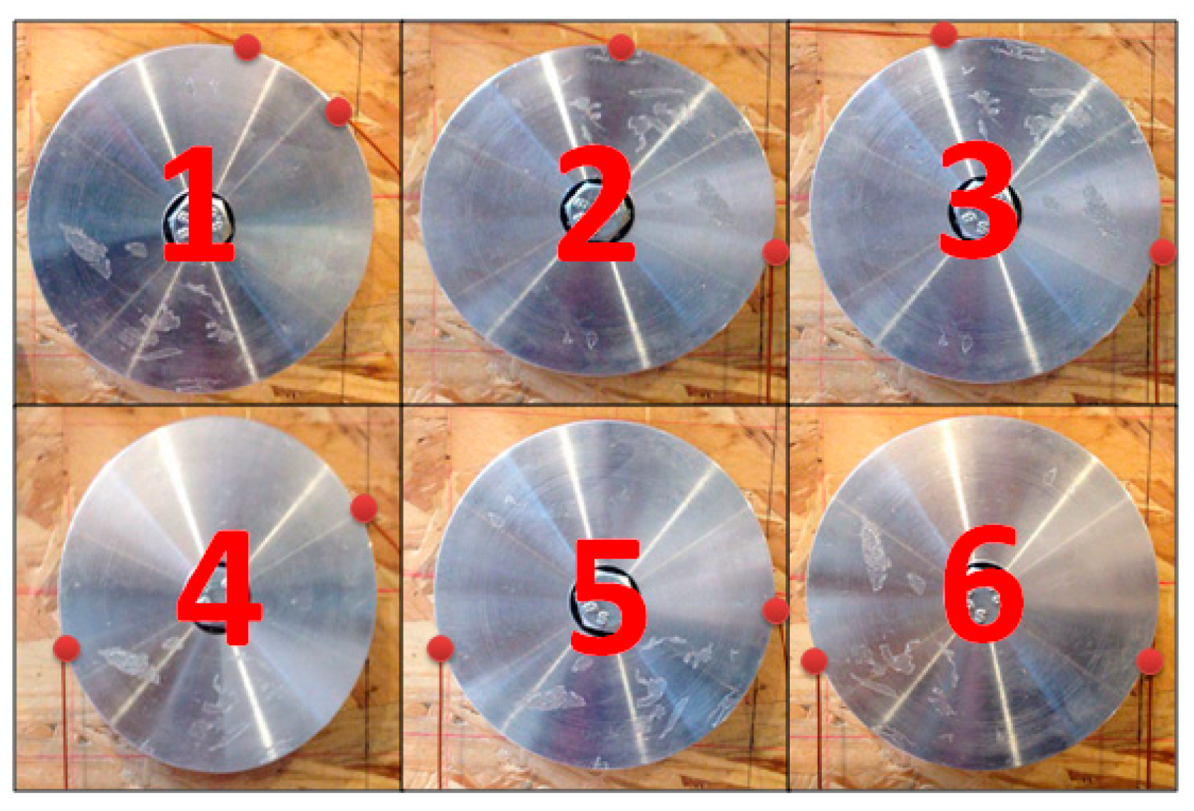
For the six fixtures in
Figure 10, the same enameled wire (0.95 × 10
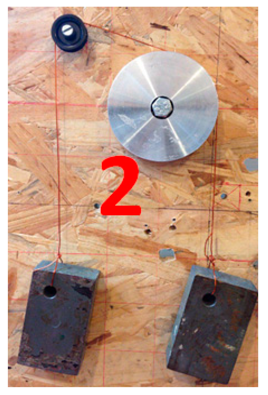
−3 m) was used with different occupancy lengths shown in red dots on the discs. In each case, a mass of 1.3 kg on each side allows the wire to be stretched as shown in
Figure 11. The results are given in
Table 2. The greater the contact length, the larger the capacitance.
5. Results and Discussion
The Laboratoire Systèmes Electrotechniques et Environnement (LSEE), The Electrotechnical Systems and Environment Laboratory (LSEE), is a university research laboratory that has a laboratory-scale enameling line. The effectiveness of this device is verified on an enamelled wire sample manufactured by this line, without worrying about the centering of the copper conductor. The insulation is based on the classical PAI-PEI insulation of 0.95 × 10⁻³ m.
The configuration 2 has been used in order to have maximum contact between the wire and the disc, making sure to have a low amount of stretched wire. If we assume that the difference in capacitance is due only to the difference in thicknesses, we can calculate the corresponding thicknesses in order to analyze their values.
The voltages at the output of the electronic board were measured.
V1 = 3.171 V,
V2 = 3.292 V and
Vd = 0.303 V are measured for the capacitors 1, 2 and the output of the comparator, respectively (
Table 3). They are converted into frequency according to the datasheet of the converter, namely the following:
We know the frequency makes it possible to calculate the capacitance from the astable circuit component value.
Equation (3) allows us to return to the values of the thicknesses of the dielectrics of our two capacitors. As
For the used system, the capacitance is as follows:
C: capacitance of the capacitor (F)
ɛ0: permittivity of the vacuum (8.854 × 10⁻¹² F·m−1)
ɛr: relative permittivity of the insulation (unitless)
R1: radius of the wire (m)
e: insulation thickness (m)
RD: disc radius (m)
The results are given in
Table 3. The length of the wire that is in contact with the disc is not known with precision. However, by using the above formula, it is assumed that it is exactly half of the circumference of the disc.
This example makes it possible to definitively validate the feasibility of the concept of dielectric measurement. Indeed, the deviation of the value of the capacitance results in a voltage difference.
A complete study of wire eccentricity requires training at least four capacitors to compare the thicknesses on four sides of the wire. Thus, the measuring device will be formed of four discs having a slot with a perimeter equal to a quarter of that of the wire.
6. Conclusions
The preliminary study carried out in this paper makes it possible to check the principle of the eccentricity measurement of an enameled wire by an electrical method. As it is possible to translate the thickness of the dielectric into DC voltage, it is possible to make the comparison between several thicknesses.
The device designed will be added to the wire production line available at the laboratory in order to determine the wire eccentricity. This will allow a precise adjustment at the beginning of the process and also a continuous monitoring during the manufacture of the wire. A complete study of the eccentricity of the wire requires the formation of at least four capacitors to compare the thickness on the four sides of the wire.
Author Contributions
Conceptualization, G.V.; experiments, A.K.; validation, formal analysis, S.A.-A., A.K. and G.V.; writing—original draft preparation, S.A.-A. and A.K.; reviewing, G.V. All authors have read and agreed to the published version of the manuscript.
Funding
This research received no external funding.
Institutional Review Board Statement
Not applicable.
Informed Consent Statement
Not applicable.
Data Availability Statement
The data are not publicly available due to privacy considerations.
Conflicts of Interest
The authors declare no conflict of interest.
References
- Shugg, W.T. Handbook of Electrical and Electronic Insulating Materials; IEEE Press: Piscataway, NJ, USA, 1995. [Google Scholar]
- Winkeler, M. Magnet wire enamels-which one? IEEE Electr. Insul. Mag. 1991, 7, 61–64. [Google Scholar] [CrossRef]
- IEC 60317-0-1; Specifications for Particular Types of Winding Wires-Part 0-1: General Requirements-Enamelled Round Copper Wire. IEC: Geneva, Switzerland, 2013.
- IEC 60851-5; Winding Wires–Test Methods–Part 5: Electrical Properties. IEC: Geneva, Switzerland, 2019.
- IEC 60505; Evaluation and Qualification of Electrical Insulation Systems. IEC: Geneva, Switzerland, 2011.
- IEC 60172; Test Procedures for the Determination of the Temperature Index of Enameled and Tape Wrapped Winding Wires. IEC: Geneva, Switzerland, 2015.
- Boughanmi, W. Eco-Conception des Motorisations Électriques: Application à la Machine Asynchrone. Ph.D. Thesis, Electrical Power Engineering of Université d’Artois, Béthune, France, 2012. [Google Scholar]
- Boughanmi, W.; Manata, J.P.; Roger, D.; Jacq, T.; Streiff, F. Life cycle assessment of three-phase electrical machines in continuous operation. IET Electr. Power Appl. 2012, 6, 277–285. [Google Scholar] [CrossRef]
- Ait-Amar, S.; Ben Fatallah, M.; Habas, A.; Habas, J.P.; Notingher, P.; Frezel, P. Properties of a new ecofficient coating for magnet wire. In Proceedings of the 2013 IEEE International Conference on Solid Dielectrics (ICSD), Bologna, Italy, 30 June–4 July 2013; pp. 553–556. [Google Scholar]
- Ait-Amar, S.; Roger, D.; Vélu, G.; Fatallah, M.B.; Habas, A.; Habas, J.; Notingher, P.; Frezel, P. Dielectric parameters study of insulation wire free of volatile organic compound. In Proceedings of the 2012 Annual Report Conference on Electrical Insulation and Dielectric Phenomena, Montreal, QC, Canada, 14–17 October 2012; pp. 866–869. [Google Scholar]
- Stone, G.C.; Culbert, I.; Boulter, E.A.; Dhirani, H. Electrical Insulation for Rotating Machines-Design, Evaluation, Aging, Testing, and Repair; IEEE Press: Piscataway, NJ, USA, 2004. [Google Scholar]
- IEC 60270; High-Voltage Test Techniques, Partial Discharge Measurements. IEC: Geneva, Switzerland, 2001.
- Gianoglio, C.; Ragusa, E.; Gastaldo, P.; Gallesi, F.; Guastavino, F. Online Predictive Maintenance Monitoring Adopting Convolutional Neural Networks. Energies 2021, 14, 4711. [Google Scholar] [CrossRef]
- Florkowski, M.; Florkowska, B.; Zydron, P. Partial Discharges in Insulating Systems of Low Voltage Electric Motors Fed by Power Electronics—Twisted-Pair Samples Evaluation. Energies 2019, 12, 768. [Google Scholar] [CrossRef] [Green Version]
- Höpner, V.N.; Wilhelm, V.E. Insulation Life Span of Low-Voltage Electric Motors—A Survey. Energies 2021, 14, 1738. [Google Scholar] [CrossRef]
- Available online: www.zumbach.com (accessed on 16 December 2021).
- Available online: www.sikora.net (accessed on 16 December 2021).
- Du, W.Y. Resistive, Capacitive, Inductive, and Magnetic Sensor Technologies; CRC Press: Boca Raton, FL, USA, 2015. [Google Scholar]
- Kitchin, C.; Counts, L. A Designer’s Guide to Instrumentation Amplifiers; Analog Devices, Inc.: Wilmington, MA, USA, 2006. [Google Scholar]
| Publisher’s Note: MDPI stays neutral with regard to jurisdictional claims in published maps and institutional affiliations. |
© 2022 by the authors. Licensee MDPI, Basel, Switzerland. This article is an open access article distributed under the terms and conditions of the Creative Commons Attribution (CC BY) license (https://creativecommons.org/licenses/by/4.0/).


