1. Introduction
The environmental constraints of energy use have become increasingly evident in recent times. The decarbonization of the energy sector is a very complex issue in which many environmental, economic, technical, social, and political aspects need to be considered simultaneously [
1,
2,
3]. An analysis based on the optimization of decarbonation pathways, and the flexibility requirements in highly renewable power systems, is presented in [
4]. In [
5], the historical development of the global decarbonization process and an assessment of the technology options for decarbonization in each sector are discussed. Current research on the transition to a decarbonized energy system in the future is dominated by renewable energy solutions and energy storage [
6,
7]. The author of [
8] compares levelized costs of electricity (LCOE) for different electricity generation technologies, including both fossil and renewable sources, by considering a wide range of values for each of their determinants. In [
9,
10], the economic profitability of sizing photovoltaic systems without storage is analyzed. A model-based decarbonization pathway for Europe’s electricity supply system until 2050 is presented in [
11]. Therefore, the current concerns in the field of energy generation are oriented towards the application of technologies with the least impact on the environment [
12,
13,
14]; however, there are also opportunities for commercially mature technologies that use a combination of other low-carbon energy sources and mixed technologies. Furthermore, final energy consumption must be controlled and managed by closely monitoring energy efficiency and diversifying the primary energy sources [
15,
16]. A resilient power system is generally characterized by high redundancy, functional diversity, adaptability, and modularity [
17]. In this context, combined heat and power (CHP), or cogeneration, is significantly more efficient than separate generation. Cogeneration significantly reduces primary energy consumption and consequently reduces greenhouse gas emissions [
18,
19]. A cogeneration system is not a single technology, but an energy system that can be structured according to the needs of the end energy user. The prime mover that drives the system is usually identified as the type of cogeneration system [
20].
The ability to extract more useful energy from the primary energy source is the main technical advantage of a cogeneration system compared with traditional power systems, such as conventional power plants that only generate electricity and boilers that only produce steam or hot water for final users.
Promoting high-efficiency cogeneration [
21] based on the demand for useful heat is a priority for many governments, given the potential benefits of cogeneration in terms of saving primary energy, avoiding grid losses, and reducing greenhouse gas emissions. In this sense, there are many support schemes either for investment support (capital grants, exemptions, or reductions in purchases of goods) or for operating support (price subsidies, green certificates, auction schemes, and tax exemptions or deductions).
Another factor that has significantly contributed to the expansion of cogeneration applications is the diversity of primary energy sources, both conventional and renewable, that can be used, and the ease with which one can switch from one primary energy source to another in the case of the same technology [
22,
23,
24,
25,
26].
The efficient use of natural gas in cogeneration applications is the main aim of this study. Compared with other fossil fuels, the use of natural gas has a much lower impact on the environment in terms of carbon dioxide emissions; thus, the continued use of natural gas seems to be one solution for the energy transition to carbon-free power generation. In the coming decades, natural gas will play an important role in the energy sector, replacing coal in energy production, and ensuring the flexibility of energy systems [
27,
28,
29]. The natural gas industry is also moving towards a gradual transition to low carbon, decarbonate, and renewable gases. With the help of carbon capture and sequestration technology, natural gas and the related infrastructure will play an important role in the development of the hydrogen economy. Natural gas transmission and distribution infrastructure can help achieve decarbonization targets by gradually integrating renewable gases, such as hydrogen and biomethane, thus ensuring the transport and storage of these gases. The production of energy from renewable sources, mainly photovoltaic and wind, is fluctuating, but this technology allows the conversion of excess electricity into hydrogen and then biomethane in a secondary process [
30,
31,
32]. Hydrogen and biomethane can then be introduced into the natural gas network for various uses in domestic and industrial consumption. New gas-to-power and power-to-X concepts can provide greater stability and security for energy supplies [
33,
34,
35,
36]. Power-to-gas is considered a promising technology for seasonal renewable energy storage, enabling a bidirectional coupling of electricity and gas grids. The use of existing natural gas transmission infrastructure for the transport of hydrogen is an efficient solution for the large-scale development of this technology [
37]. The convergence of these systems can ensure a sustainable supply of electricity, heat, and fuel based on wind and solar energy, using the existing networks and infrastructures for distribution and storage.
The main contributions and novelty elements of this paper can be summarized as follows:
The heat demand of a drug factory was analyzed in detail and with high accuracy to identify the hourly, daily, weekly, monthly, and annual load profiles;
Meeting the variations in heat demand, flattening the load duration curve, and increasing energy efficiency were the challenges we overcame.
The paper is organized as follows.
Section 2 presents the methodology used. The technical and economic viability of cogeneration and trigeneration solutions is discussed in
Section 3. The findings and their implications are summarized in
Section 4. Finally, the conclusions of this paper are presented in
Section 5.
2. Materials and Methods
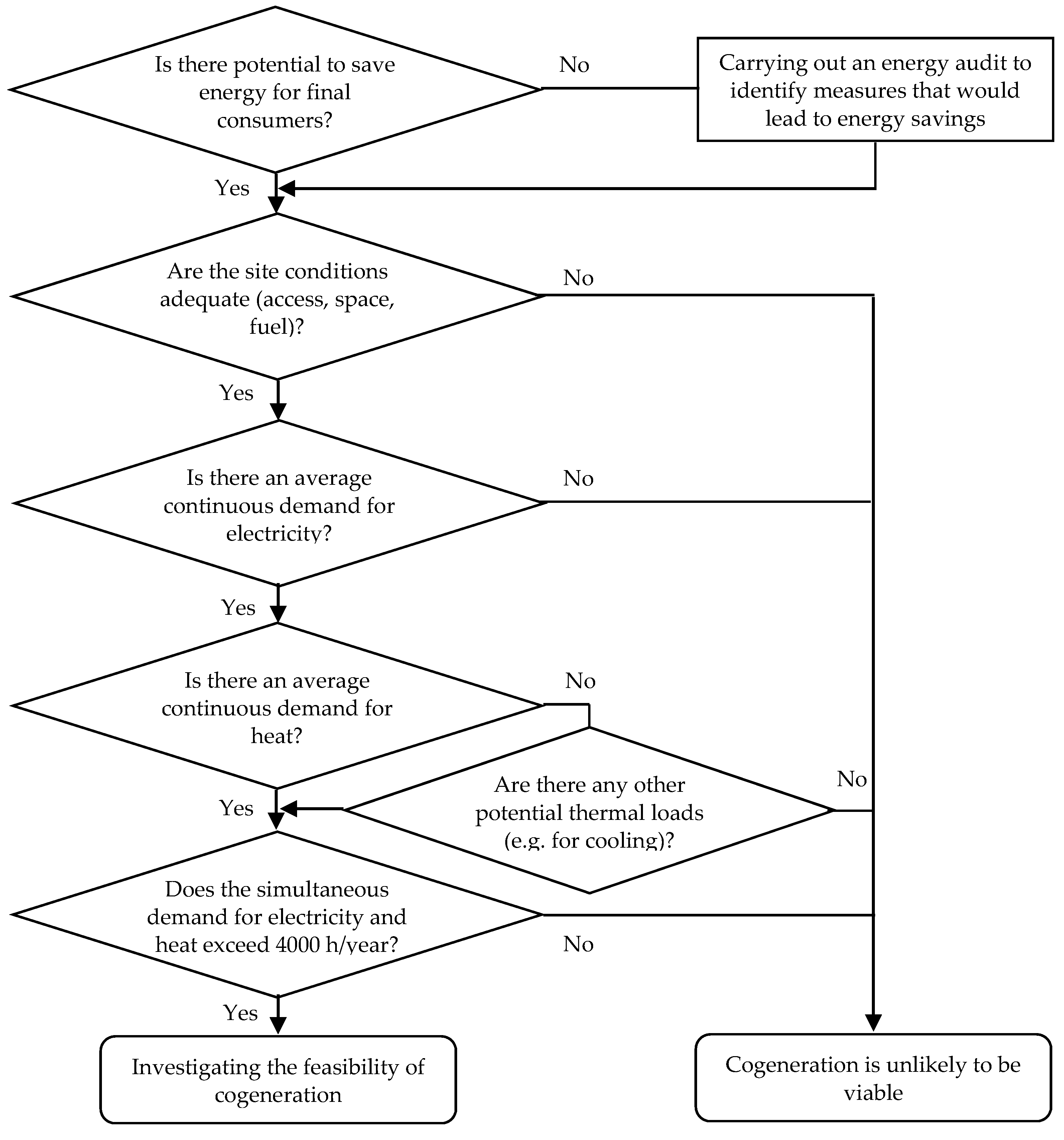
The process for assessing the appropriateness of applying cogeneration to a site begins with an assessment of technical potential and continues with an assessment of cost-effectiveness [
38].
Figure 1 shows the steps in the initial assessment of a cogeneration application. As a first step, the compatibility of any existing heating system with the proposed cogeneration plant must be established. This will help the designer to use the existing infrastructure. Important user features to consider include electricity and heat demand profiles, the predominant costs of conventional utilities, and any physical location restrictions.
A successful evaluation study, despite having the characteristics of an analytical tool, involves a practical approach, with extensive fieldwork, data collection, and measurements, but with a rigorous technical and financial analysis. The aid of a computer is very useful in such analyses, with its function being to complete and support the main activities of field work and direct metering.
Avoiding the oversizing of the cogeneration plant by applying traditional energy efficiency measures is also an efficient way to reduce costs; therefore, it is necessary to carry out an energy audit in advance, and to ensure that potential energy saving opportunities are implemented before adopting the cogeneration and trigeneration solutions. The correct identification and consideration of the actual energy demand of the analyzed contour will help to avoid the problem of oversizing the cogeneration system.
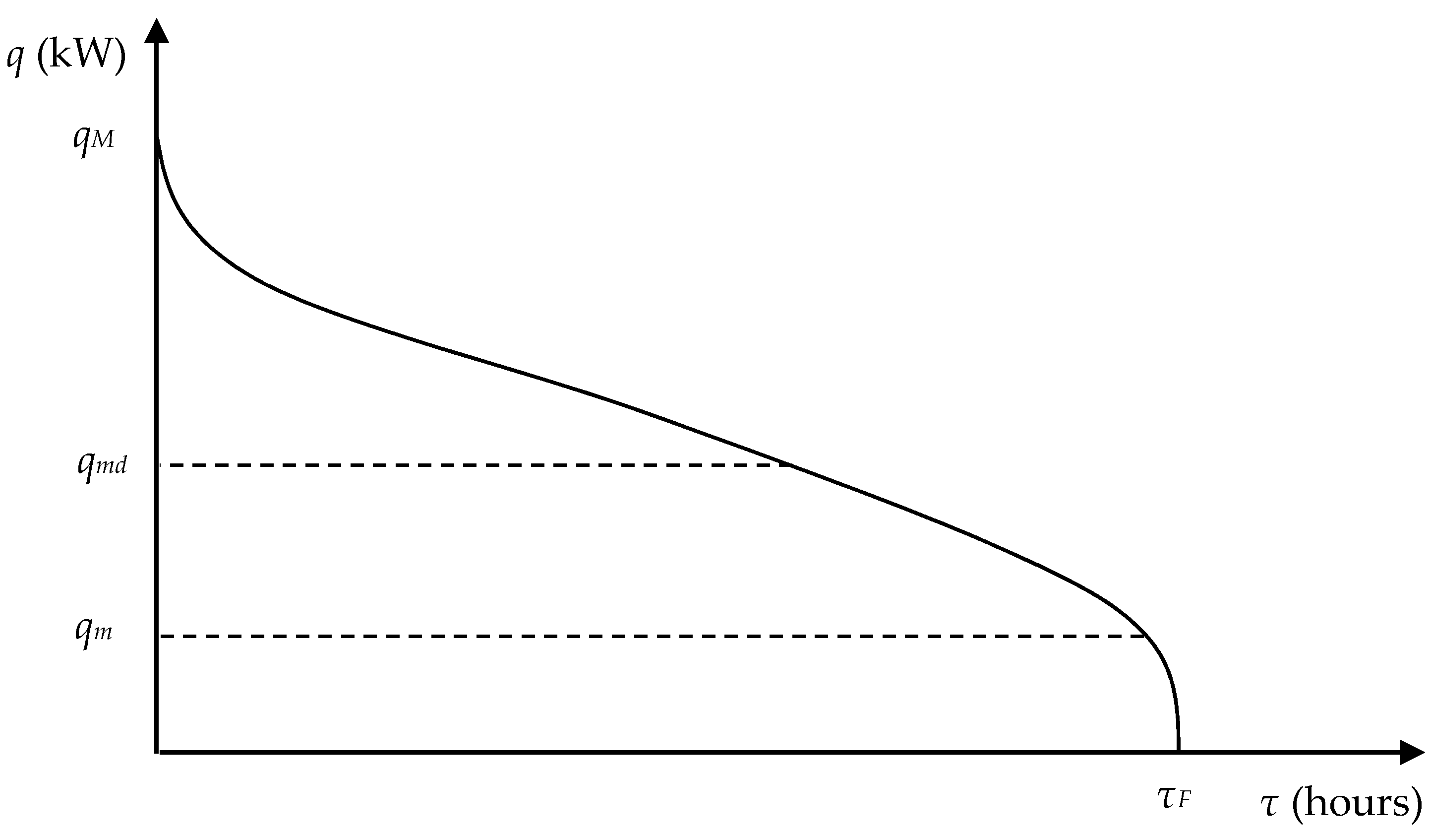
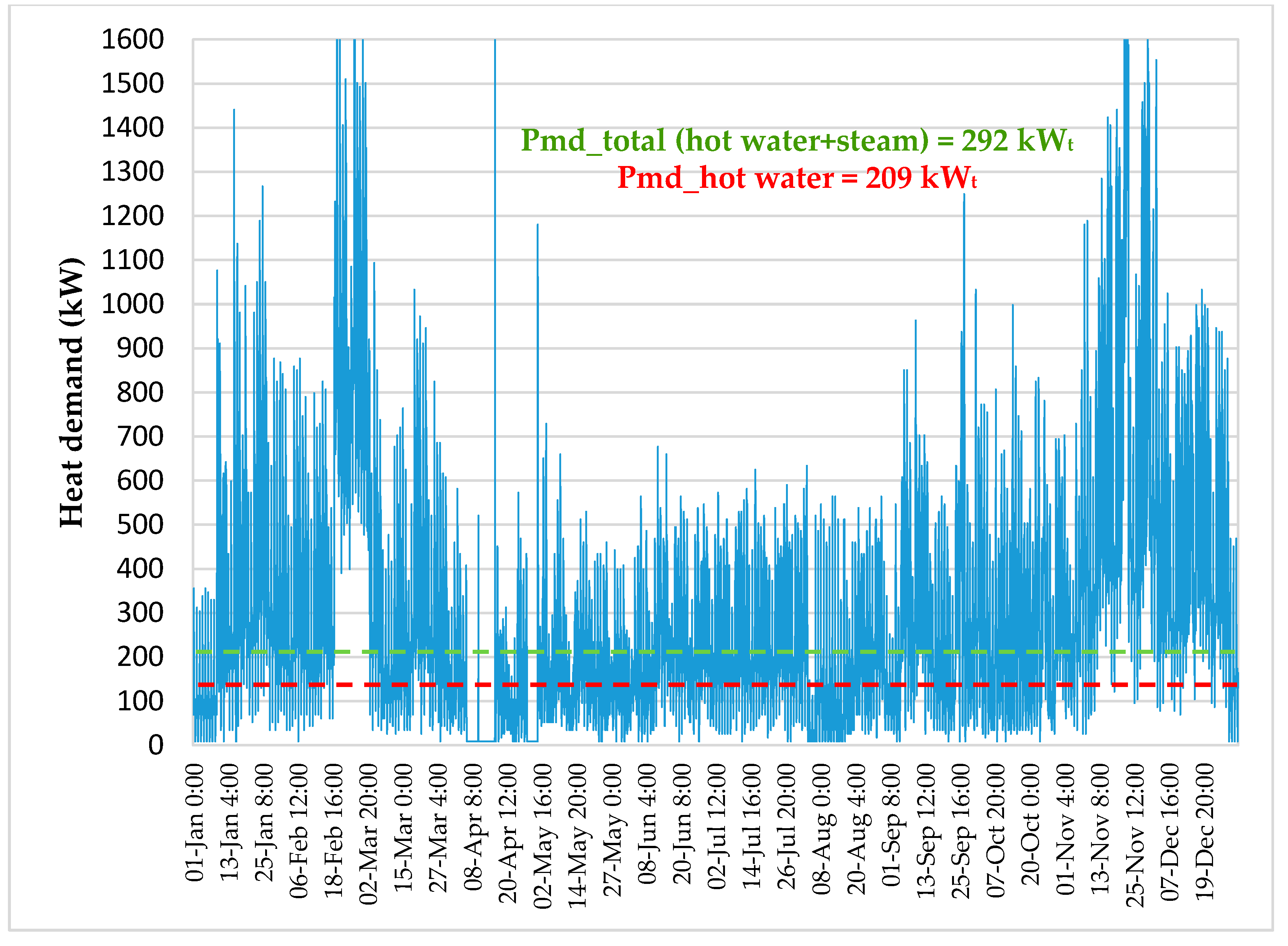
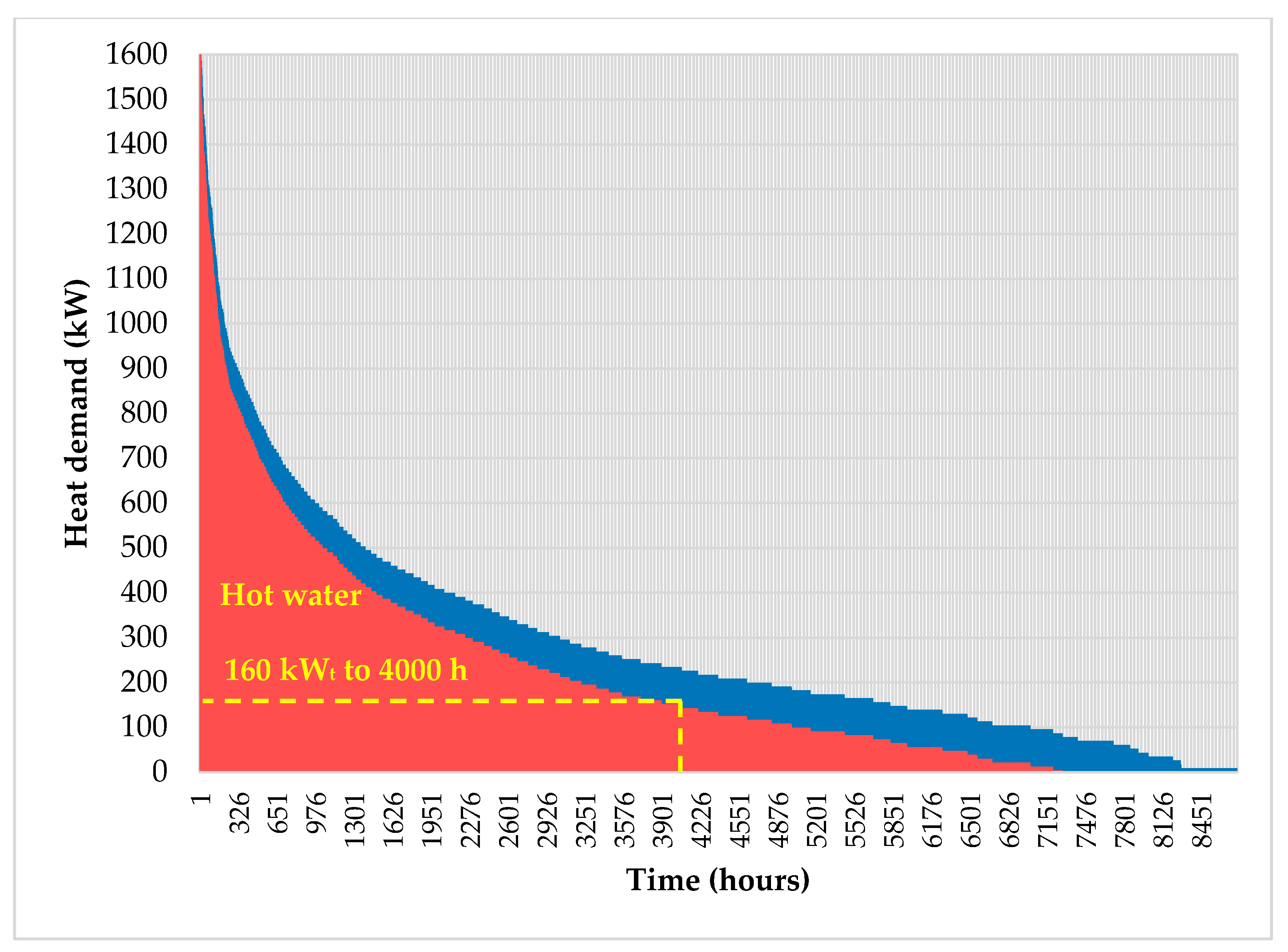
The consumption curve or load profile illustrates the variation in the final energy demand over a certain time interval. A load curve describes the variation in electrical or thermal power over time (day, month, year). The load duration curve for the heat demand is obtained from the chronological load curve. The load duration curve is a curve ordered by the value of the power, starting from the highest value to the lowest (
Figure 2). Thus, the load duration curve is always a downward curve and shows how long a certain power is required.
The shape of the graded curve
q =
f(
τ) can be expressed analytically using the Sochinsky–Rossander equation [
39,
40]:
where the coefficient of non-uniformity
β is:
and where:
qm is the minimum heat demand (kW
t);
qmd represents the average heat demand (kW
t);
qM denotes the maximum heat demand (kW
t); and
τF stands for the annual time of heat demand (hours/year).
The annual heat demand is determined either by summing the records of the heat meters (steam and/or hot water, if any) or by processing the fuel consumption records. Heat consumption is almost always variable over time, with a “basic” component (long/quasi-constant) overlapping “peak” components (shorter/interrupted). Variations in consumption are determined by both the outside temperature and the specific periods, durations, and regimes of the technological processes.
The correct determination of the final energy consumption curves (electricity, heat, cooling) is of particular importance for the choice of cogeneration technology. With the help of the annual graded heat consumption curve, the main indicators necessary for the choice of cogeneration solution will be determined: cogeneration coefficient and duration of annual use of the installed thermal power.
The annual heat demand
Q:
The cogeneration coefficient
αcogen:
The amount of heat generated by the cogeneration plant
QCHP:
The duration of annual use of installed thermal power
τmdCHP:
The total fuel consumption of the cogeneration plant
WCHP:
The fuel consumption for cogeneration heat generation
WhCHP:
The electricity generated by the cogeneration plant
ECHP:
The fuel consumption for cogeneration electricity generation
WeCHP:
The cost of fuel for the generation of electricity in cogeneration
CeCHP:
The cost of electricity that is no longer purchased from the public network
Cenetwork:
The operating and maintenance costs (O&M) of CHP
CO&MCHP:
The annual saving in monetary units
Ct (the yearly revenue):
The investment cost,
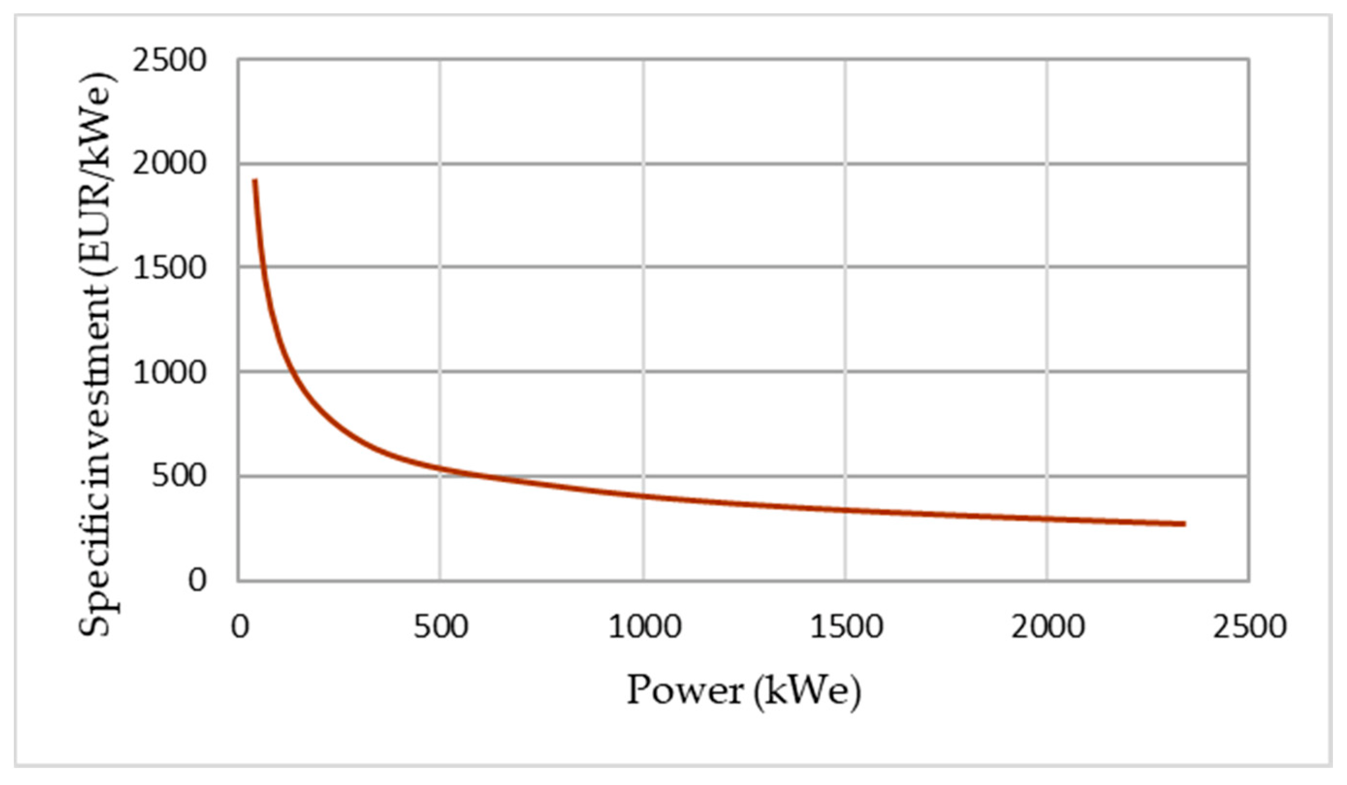
C0, refers to the costs of equipment and services required for the installation and commissioning of a cogeneration or trigeneration system. The unit value of investment costs varies significantly between different cogeneration technologies. However, basic economies of scale logic apply to all cogeneration technologies in terms of installed unit capacity.
Figure 3 shows the specific investment
isp depending on the installed capacity
Pne of the cogeneration unit in the case of reciprocating gas engines [
41]:
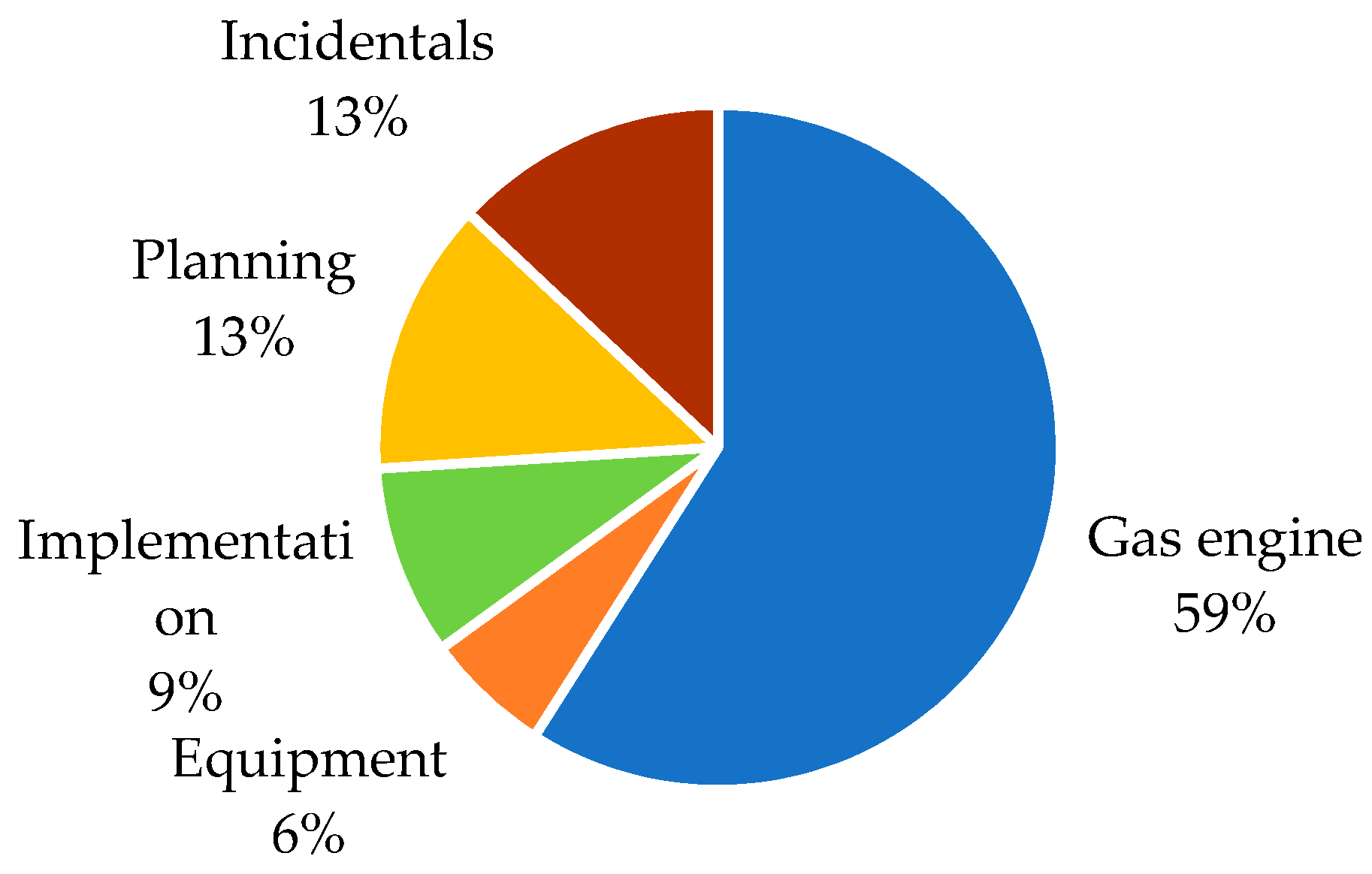
All costs associated with the cogeneration project must be considered; thus, the costs for planning, design, construction, operation, and maintenance (O&M) are added to the investment costs of cogeneration units. The share of operation and maintenance (O&M) costs is usually in the range of 1.5–3.0% per year of total capital costs. An example of the distribution of investment costs is shown in
Figure 4 [
41]. The technology and size of CHP unit may influence these shares.
The investment cost (
C0), the annual saving in monetary units (
Ct), and the discount rate (
i) are taken into account for the selection of the optimal variant from an economic, technological and ecological point of view. The evaluation is made during the lifetime of the investment in years (
N). Several economic indicators can be used to assess the technical and economic viability of the proposed technical solutions [
42]:
where:
NPV is net present value;
IRR represents internal rate of return;
SPBP indicates a simple payback period.
Primary energy saving (
PES) is used to compare cogeneration production and separate production of heat and electricity using the same type of fuel [
43]:
or:
where:
Wsep is the primary energy consumption for separate production of electricity and heat (kWh);
WCHP indicates the primary energy consumption in cogeneration (kWh);
ηhCHP represents the heat efficiency of CHP (%);
ηeCHP denotes the electricity efficiency of CHP (%);
ηhRef stands for the reference heat efficiency (%);
ηeRef represents the reference electricity efficiency (%); and
ploss is correction factor for
ηeRef.
The carbon dioxide emissions are calculated by use of the following equation:
where
fCO2 is emission factor (for natural gas
fCO2 = 0.205 kgCO
2/kWh).
In this paper, the cogeneration and trigeneration solutions are compared with the reference scenario in which the heat is generated separately from the gas boilers and the electricity is purchased from the grid. In
Table 1, we present the prices of natural gas and electricity that were taken into account in our analysis, at the time of the analysis in 2021 [
44,
45]. The harmonized reference values for the efficiency of separate heat production and separate electricity production (established on the basis of Directive 2012/27/EU) are given in
Table 2 [
46].
Trigeneration and heat storage are used as solutions to increase the flattening degree of the heat demand curve
μ and to increase the operating time of the cogeneration units:
Trigeneration is an extension of cogeneration that includes cooling as the final form of energy use. The combined generation of electricity, heat, and cooling from the same primary energy source offers even more flexibility for a cogeneration plant. The extension consists of the integration of an absorption refrigeration system, which consumes the available thermal energy of the cogeneration plant in the hot season. The balance of cogeneration energy production and the demand for electricity and heat is an important challenge in the implementation of CHP units. In addition, variations in electricity and heat demand can make CHP units difficult to operate. Balancing the production and demand of electricity can be done easily if the CHP unit is connected to the public grid. In case of heat demand variations, they can be taken up using heat storage solutions [
47,
48,
49,
50,
51,
52]. Thermal energy storage (TES) will increase the flexibility of the cogeneration unit and ensure the simultaneous demand for electricity and heat.
4. The Results of the Investigations
The results of the investigations regarding the viability of cogeneration and trigeneration are highlighted in the following scenarios.
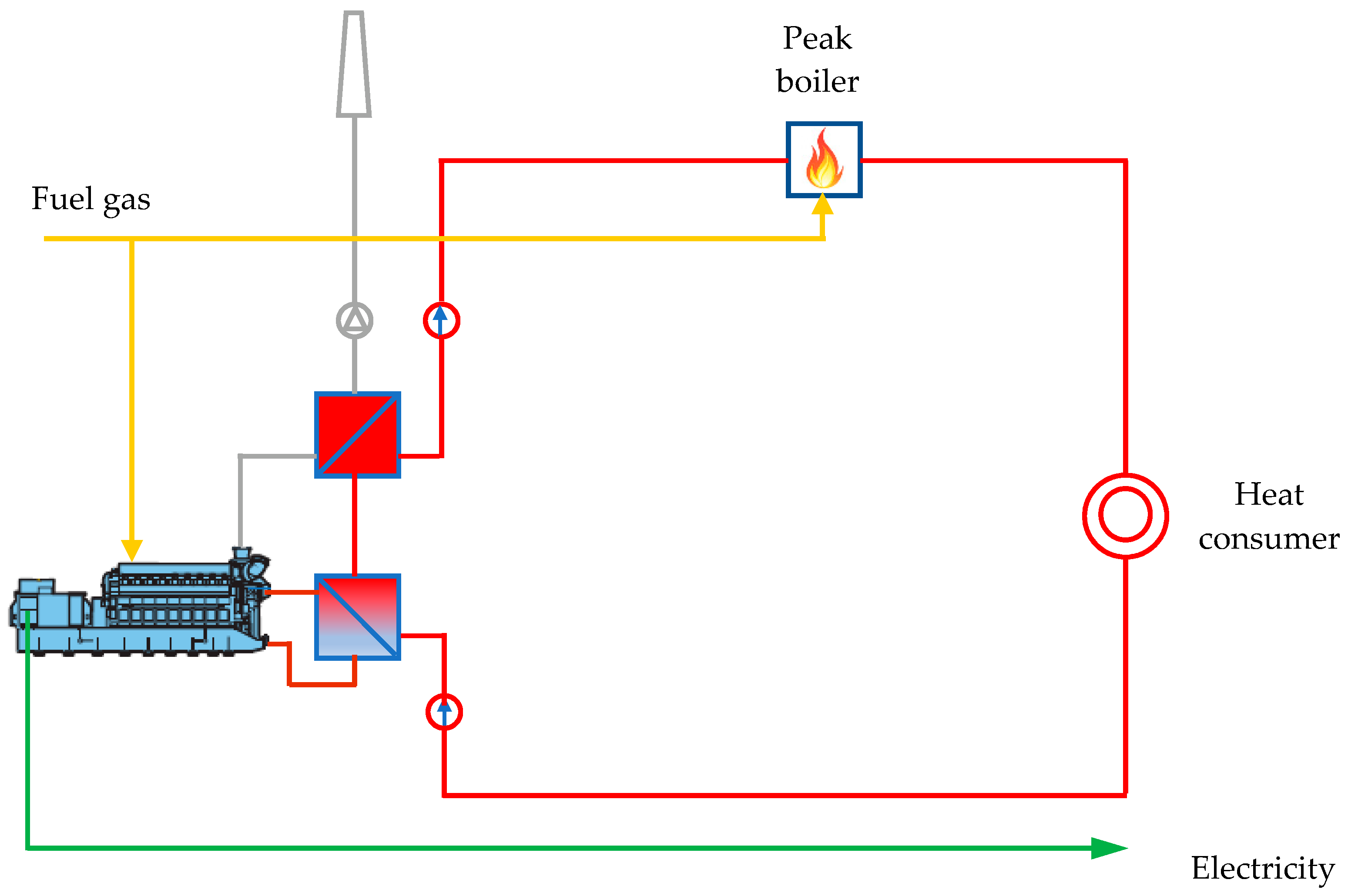
4.1. Case 1. Cogeneration (1 × 200 kWe, 1 × 256 kWt)
In the first case (
Figure 19), the economic viability of a cogeneration unit with an internal combustion engine using natural gas combustion with the following nominal characteristics is analyzed:
Electrical power: 200 kWe;
Thermal power: 256 kWt;
Fuel power: 535 kW;
Electricity efficiency: 37.38%;
Heat efficiency: 47.85%;
Overall efficiency: 85.23%.
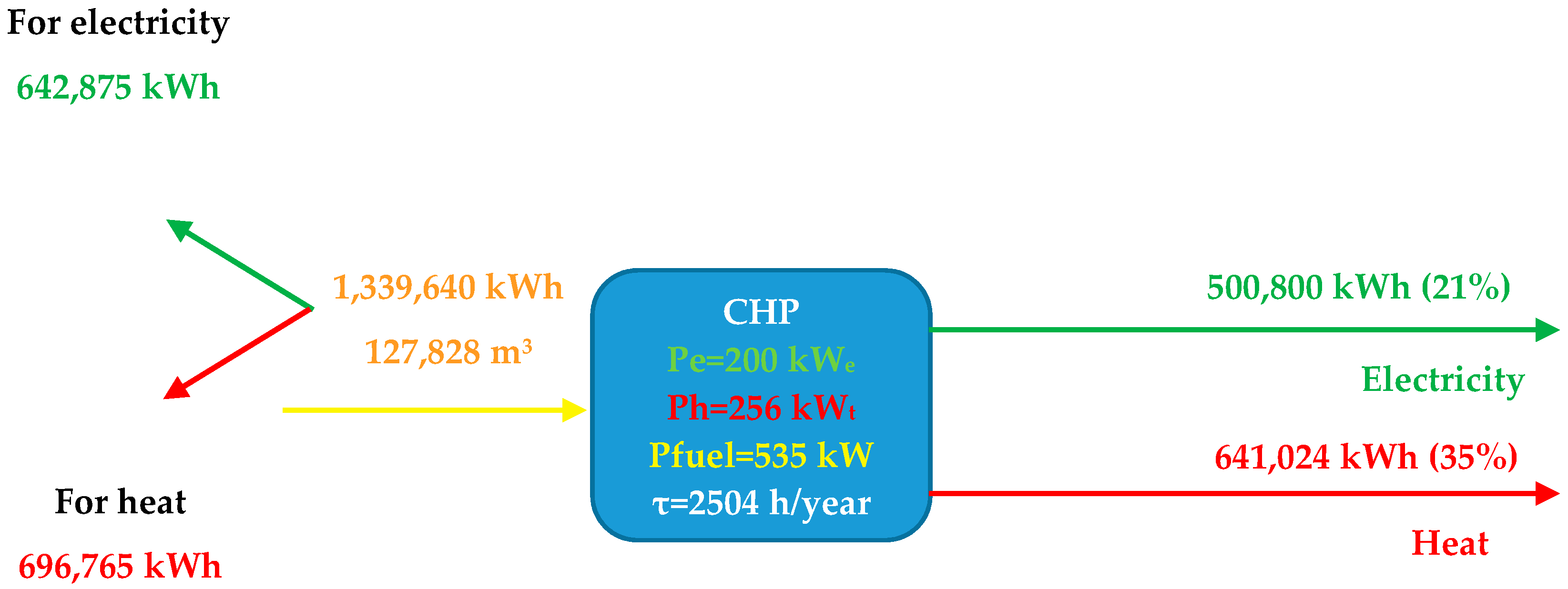
Given the load duration curve for the heat demand (
Figure 10), the operating time at the rated thermal load is 2504 h/year. The following are the characteristic data results for the cogeneration system:
Heat production: 256 × 2504 = 641,024 kWh (35% of the low temperature heat consumption in the form of hot water, recorded in the previous year of operation);
Electricity production: 200 × 2504 = 500,800 kWh (21% of electricity consumption, recorded in the previous year of operation);
Natural gas consumption: 535 × 2504 = 1,339,640 kWh (127,828 m3).
To estimate the annual savings, it is necessary to break down the fuel consumption of the two forms of useful energy generated, according to the following algorithm:
Thermal energy considered to be generated with the efficiency of the current hot water boilers: 641,024/0.92 = 696,765 kWh;
This amount is subtracted from the total amount of natural gas consumed in cogeneration, resulting in the fuel consumption for electricity generation: 1,339,640 kWh − 696,765 kWh = 642,875 kWh;
The cost of fuel consumed to generate electricity in cogeneration: 642 875 kWh × 0.036 EUR/kWh = 23,143 EUR/year;
The cost of electricity currently purchased from the public energy grid, which will be generated in cogeneration: 500,800 kWh × 0.11 EUR/kWh = 55,088 EUR/year;
Operation and maintenance cost (O&M): 7920 EUR/year;
Annual savings: 55,088 − 23,143 − 7920 = 24,025 EUR/year.
The following investment values were considered for the calculation of the payback period:
Specific investment: 1320 EUR/kWe;
Total investment: 1320 × 200 = EUR 264,000;
Payback period: EUR 264,000/24,025 EUR/year = 10.99 years.
The results obtained for this scenario are summarized in
Figure 20 and
Table 4. The scenario was also estimated when the specific investment was 20% higher (unforeseen expenses) at 1584 EUR/kW
e. This results in a payback period of 13.19 years. The reduction in CO
2 emissions in this scenario is 87,044 kgCO
2/year.
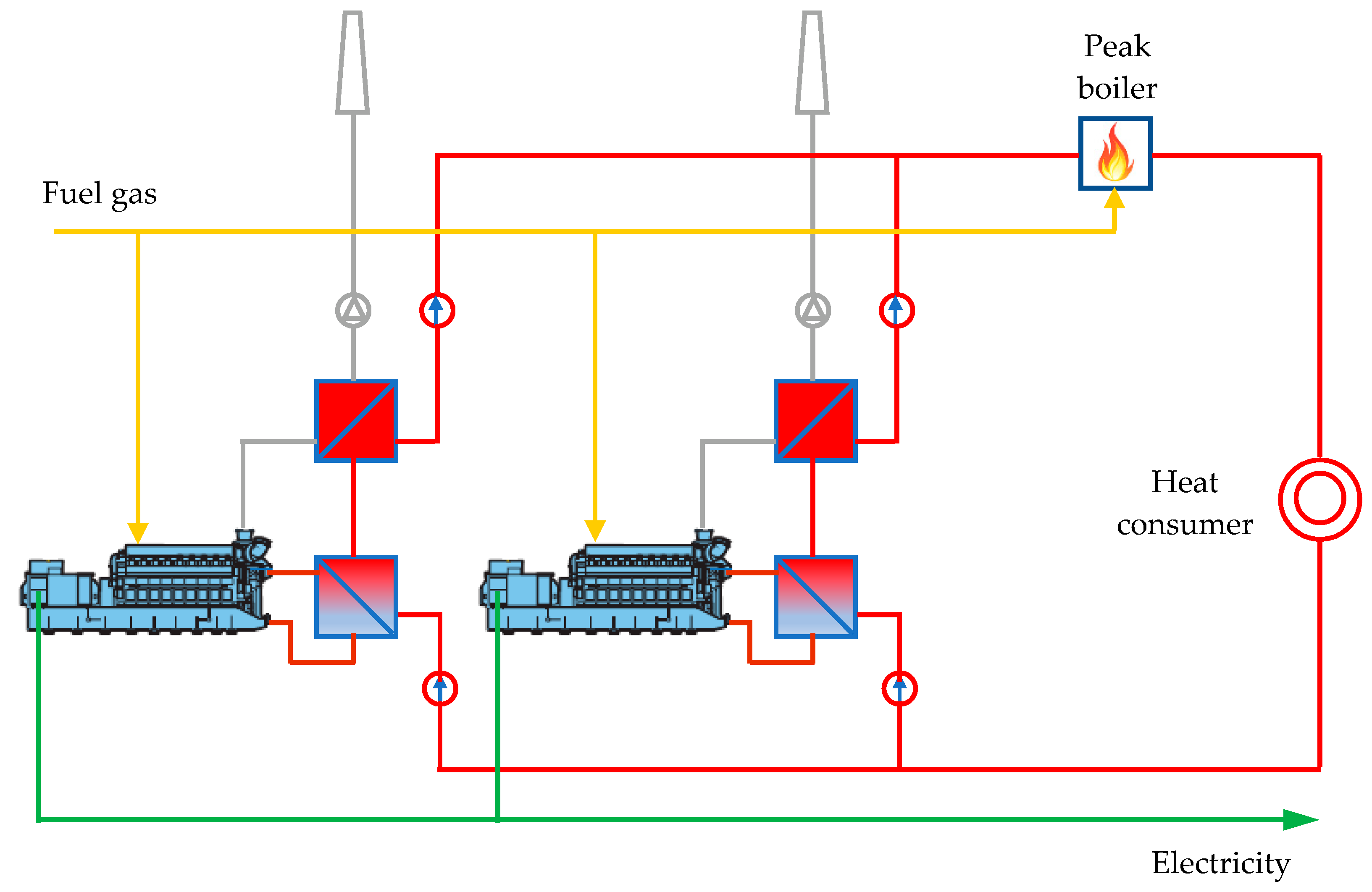
4.2. Case 2. Cogeneration (2 × 100 kWe, 2 × 130 kWt)
In the second case, the economic viability of a cogeneration system with two identical cogeneration units is analyzed (
Figure 21):
Electrical power: 2 × 100 kWe;
Thermal power: 2 × 130 kWt;
Fuel power: 2 × 271 kW;
Electricity efficiency: 36.90%;
Heat efficiency: 47.97%;
Overall efficiency: 84.87%.
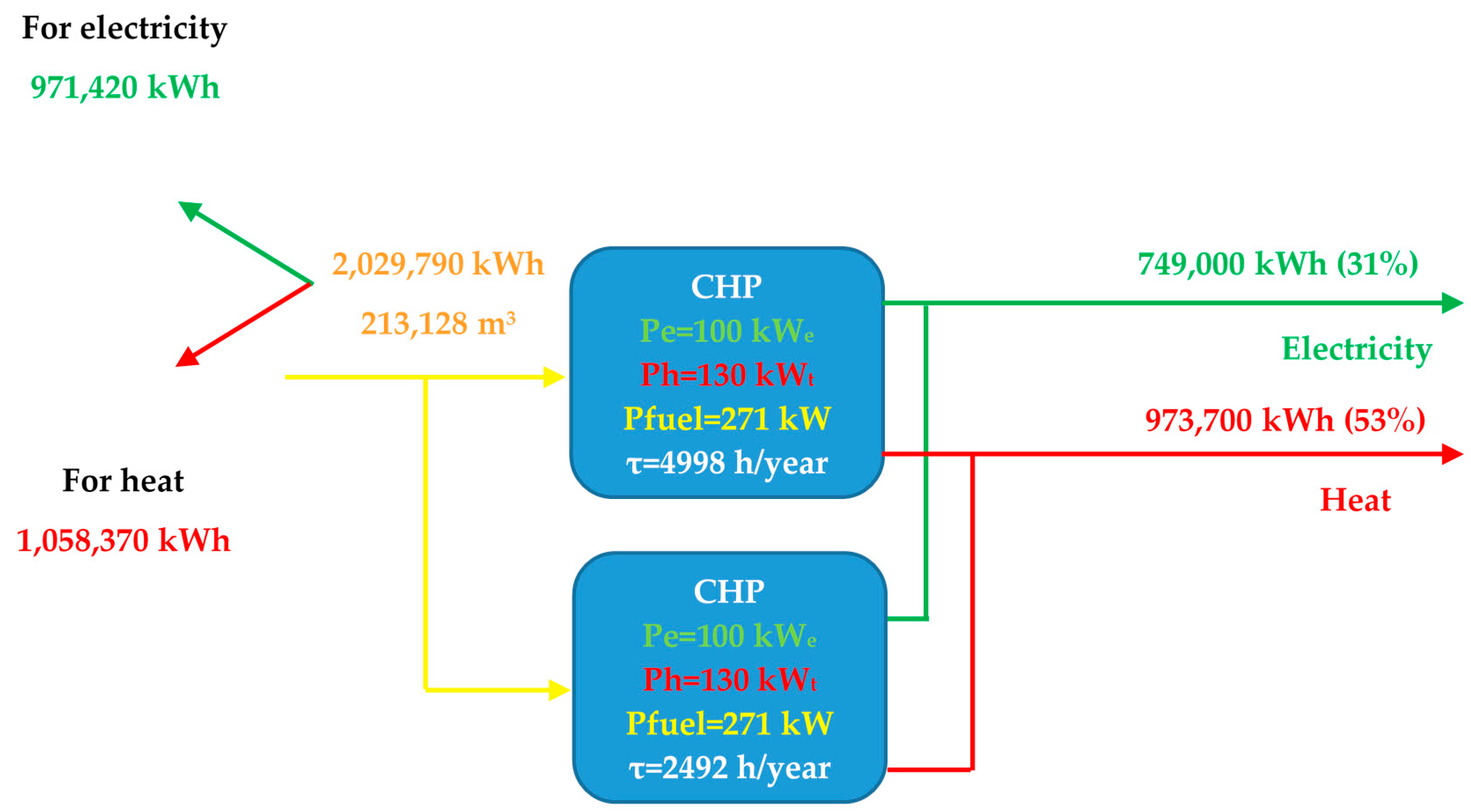
Given the load duration curve for the heat demand (
Figure 10), the operating time at the rated thermal load is 4998 h/year for the first CHP unit, and 2492 h/year for the second CHP unit. The following are the characteristic data results for the cogeneration system:
Heat production: (130 × 4998) + (130 × 2492) = 973,700 kWh (53% of the low temperature heat consumption in the form of hot water, recorded in the previous year of operation);
Electricity production: (100 × 4998) + (100 × 2492) = 749,000 kWh (31% of electricity consumption, recorded in the previous year of operation);
Natural gas consumption: (271 × 4998) + (271 × 2492) = 2,029,790 kWh (213,128 m3);
Annual savings: 37,939 EUR/year;
Total investment: 316,000 EUR/year;
Payback period: 8.33 years;
Reducing CO2 emissions: 128,429 kgCO2/year.
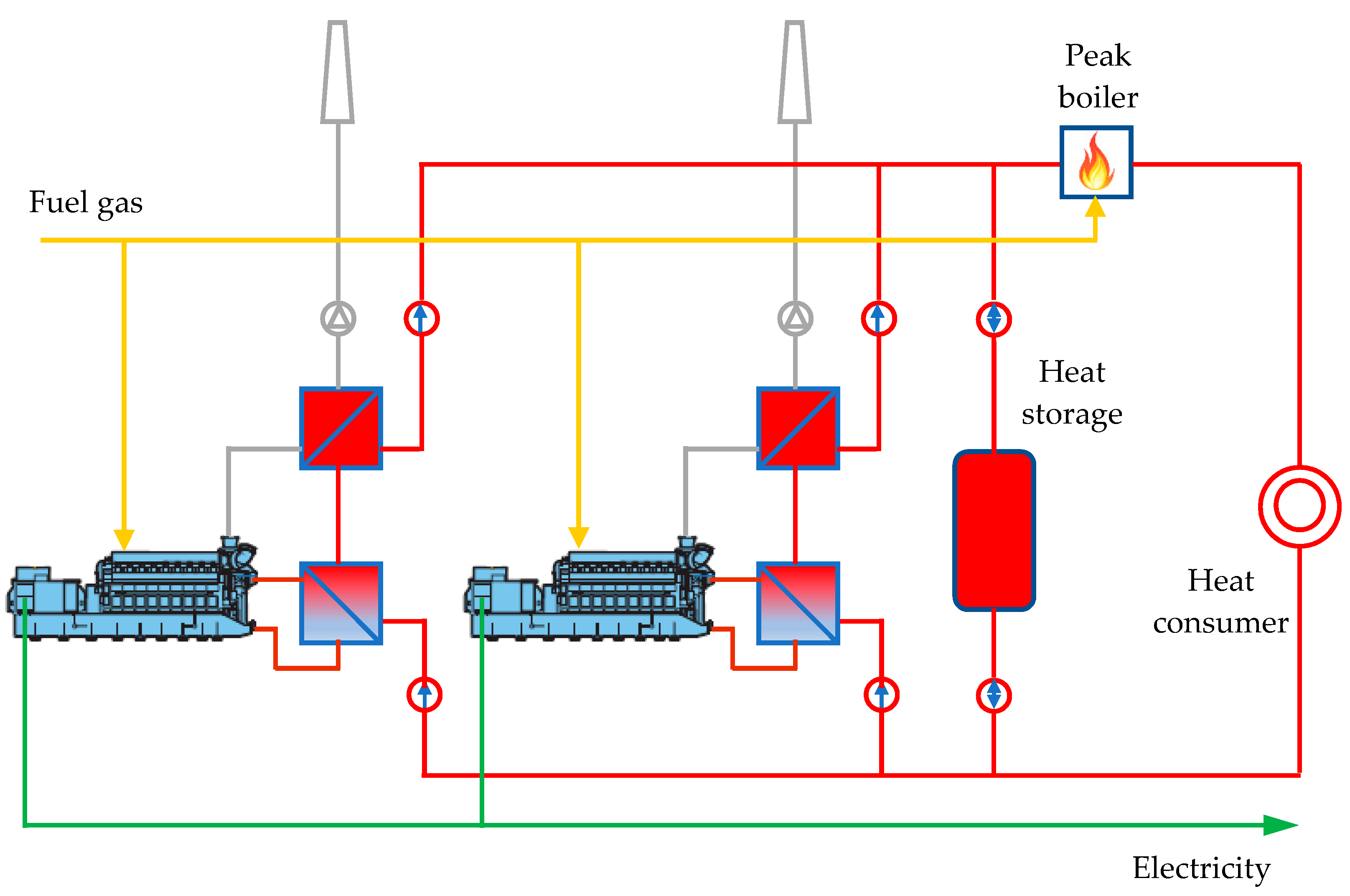
4.3. Case 3. Cogeneration (2 × 100 kWe, 2 × 130 kWt) and Heat Storage (3000 kWh)
In this scenario, in addition to the previous scenario, heat storage is used (
Figure 23) using 3000 kWh (heat accumulation 200 kW
t for an operating time of 15 h). The results obtained for this scenario are summarized in
Figure 24 and
Table 6.
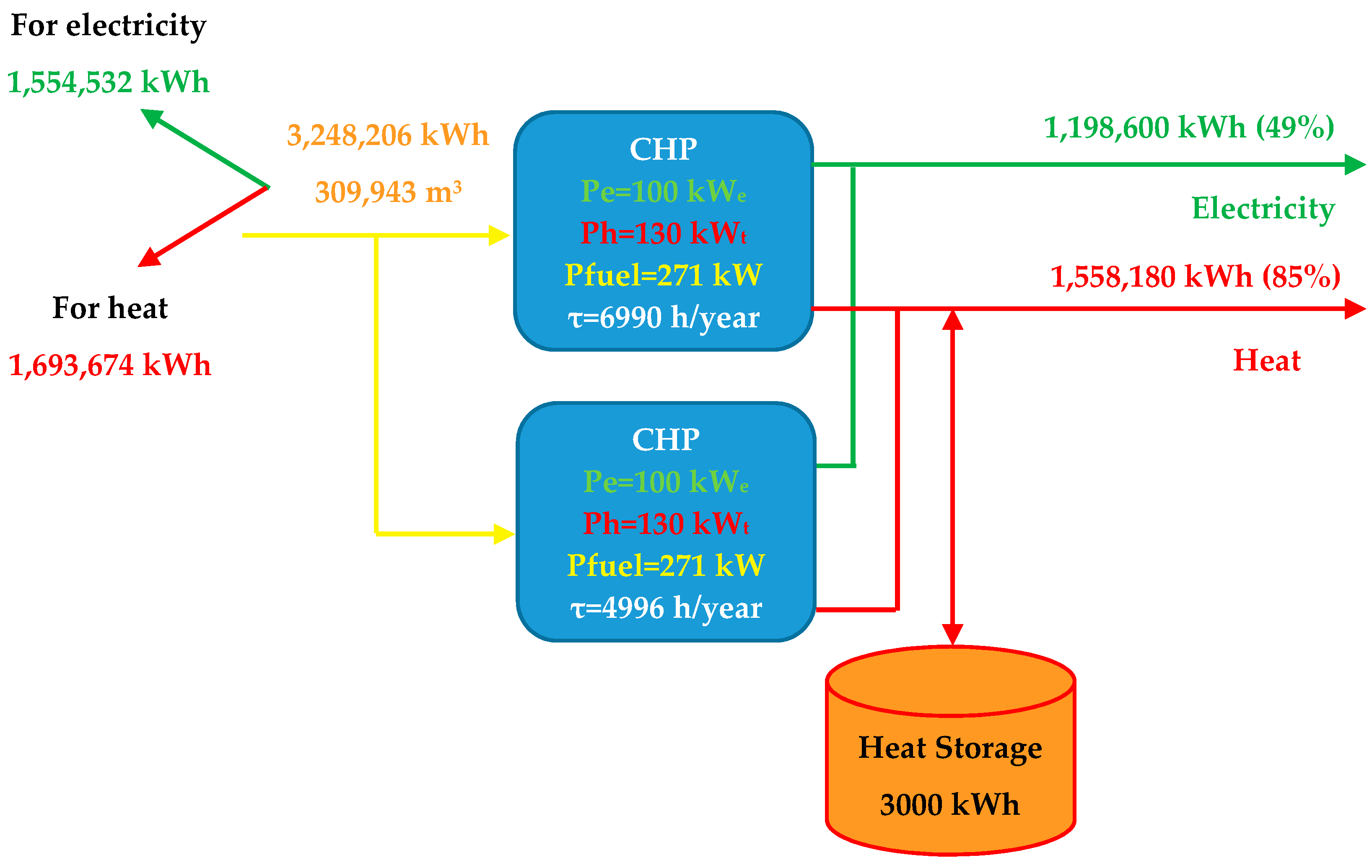
By introducing heat storage, the operating time at the rated thermal load will increase to 6990 h/year for the first CHP unit, and 4996 h/year for the second CHP unit. The following are the characteristic data results for the cogeneration system:
Heat production: (130 × 6990) + (130 × 4996) = 1,558,180 kWh (85% of the low temperature heat consumption in the form of hot water, recorded in the previous year of operation);
Electricity production: (100 × 6990) + (100 × 4996) = 1,198,600 kWh (49% of electricity consumption, recorded in the previous year of operation);
Natural gas consumption: (271 × 6990) + (271 × 4996) = 3,248,206 kWh (309,943 m3);
Annual savings: 65,503 EUR/year;
Total investment: 346,000 EUR/year;
Payback period: 5.28 years;
Reducing CO2 emissions: 205,521 kgCO2/year.
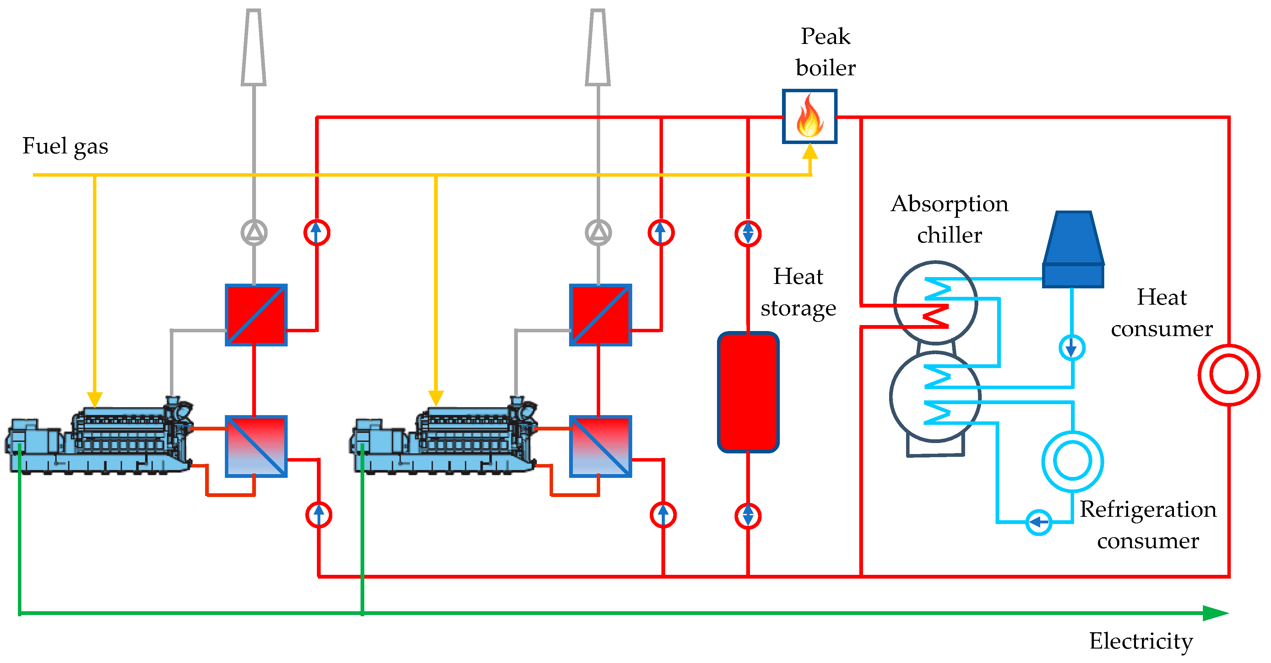
4.4. Case 4. Trigeneration (2 × 100 kWe, 2 × 130 kWt), Heat Storage (3000 kWh), and Absorption Chiller (180 kW)
In this scenario, in addition to the previous scenario, an absorption chiller is used, with a cooling power of 180 kW, and coefficient of performance (COP) = 0.7 (
Figure 25). The results obtained for this scenario are summarized in
Figure 26 and
Table 7.
The thermal potential available during the summer (hot water 80/60 °C), and which can be delivered from the cogeneration plant, was considered when sizing the absorption chiller. Therefore, for this thermal level, single-stage chiller modules were considered for their flexibility in operation.
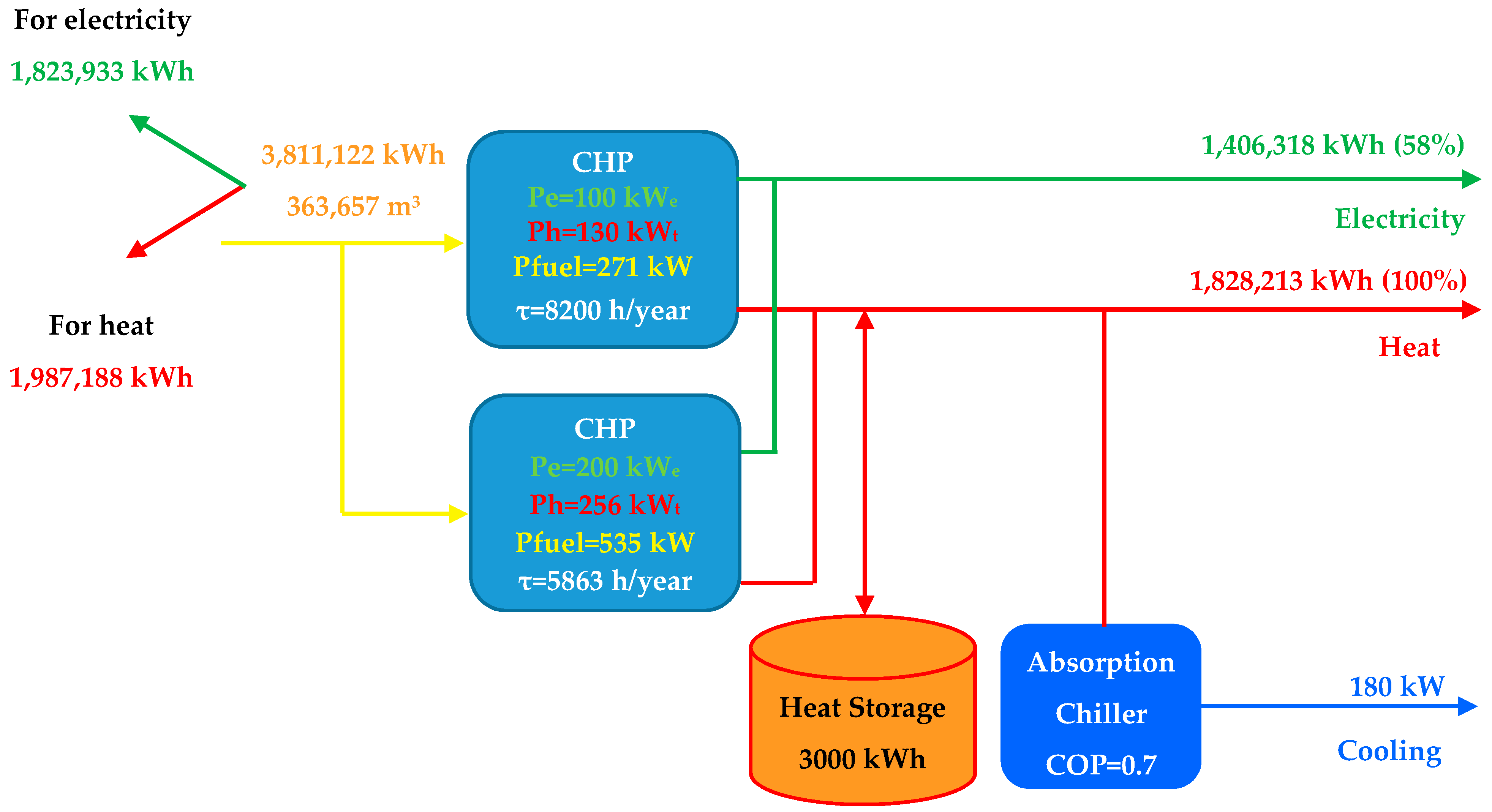
By introducing heat storage and using the heat available during the summer in an absorption refrigeration system, the operating time at the rated thermal load will increase to 8200 h/year for the first CHP unit, and 5863 h/year for the second CHP unit.
The following are the characteristic data results for the cogeneration system:
Heat production: (130 × 8200) + (130 × 5863) = 1,828,213 kWh (100% of the low temperature heat consumption in the form of hot water, recorded in the previous year of operation);
Electricity production: (100 × 8200) + (100 × 5863) = 1,406,318 kWh (58% of the low temperature heat consumption in the form of hot water, recorded in the previous year of operation);
Natural gas consumption: (271 × 8200) + (271 × 5863) = 3,811,122 kWh (363,657 m3);
Annual savings: 77,303 EUR/year;
Total investment: 391,000 EUR/year;
Payback period: 5.06 years;
Reducing CO2 emissions: 241,138 kgCO2/year.
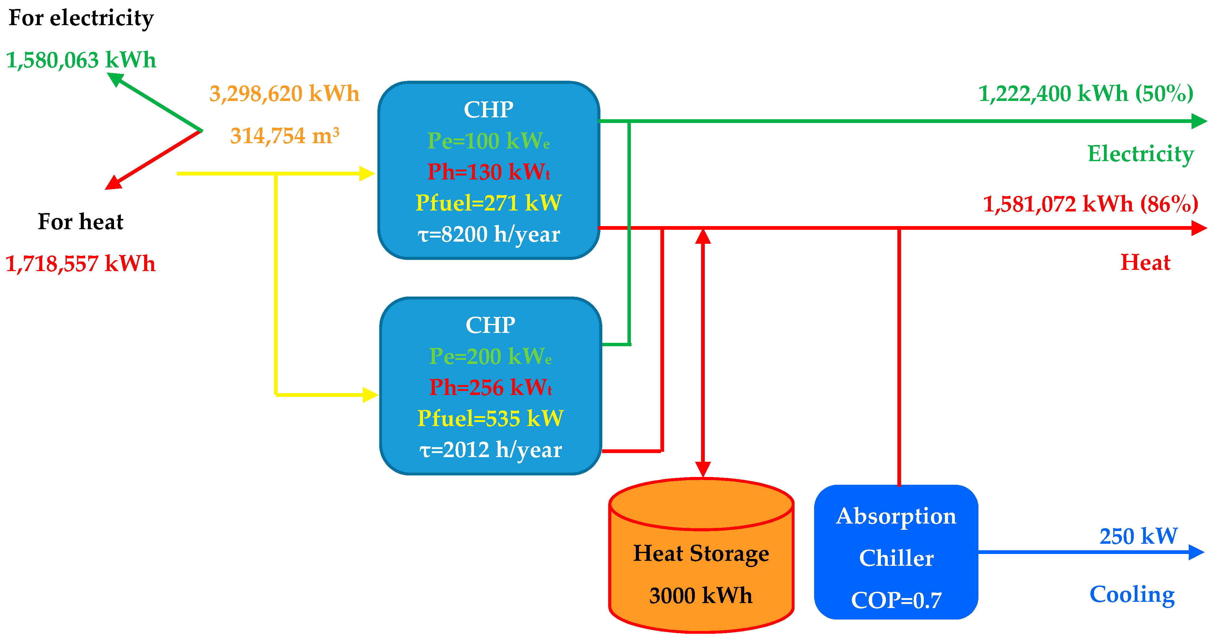
4.5. Case 5. Trigeneration (1 × 100 kWe, 1 × 200 kWe, 1 × 130 kWt, 1 × 256 kWt), Heat Storage (3000 kWh), and Absorption Chiller (250 kW)
In this scenario, the economic viability of the trigeneration system with two different cogeneration units of the type used in the previous variants is analyzed:
Electrical power: 1 × 100 kWe;
Thermal power: 1 × 130 kWt;
Fuel power: 1 × 271 kW;
Electricity efficiency: 36.90%;
Heat efficiency: 47.97%;
Overall efficiency: 84.87%;
Electrical power: 1 × 200 kWe;
Thermal power: 1 × 256 kWt;
Fuel power: 1 × 535 kW;
Electricity efficiency: 37.38%;
Heat efficiency: 47.85%;
Overall efficiency: 85.23%;
Heat storage: 3000 kWh (heat accumulation 200 kWt for an operating time of 15 h);
Absorption chiller, cooling power: 250 kW (COP = 0.7).
By introducing heat storage and using the heat available during the summer in an absorption refrigeration system, the operating time at the rated thermal load will be 8200 h/year for the first CHP unit, and 2012 h/year for the second CHP unit. It can be seen that, in this scenario, there is a thermal power reserve installed in the second CHP unit (higher power unit); therefore, the annual operating time of this CHP unit will increase with increased drug production and heat demand.
5. Summary Results and Discussion
Heat demand is the decisive factor in justifying the efficiency of the cogeneration solution and is foundational for sizing a cogeneration unit; therefore, at the installation site, the most rigid conditioning of the operating regime, in the case of cogeneration systems, is determined by the thermal consumption. The differences in electricity between the on-site consumption and the production of the CHP plant (proportional to the thermal load) are compensated, without technical difficulties, from the public electricity network to which the CHP plant is connected. In order for a cogeneration system to be viable in energy savings (with sufficient energy savings to compensate for the investment effort), the annual operating time of the cogeneration plant must be sufficiently long, loading as close as possible to the rated load. An annual operating time of at least 4000 h/year for a cogeneration unit can be considered as one of the basic rules that are necessary to abide by.
The basic question that any potential investor faces is the viability and profitability of the cogeneration solution under the specific conditions of the plant location.
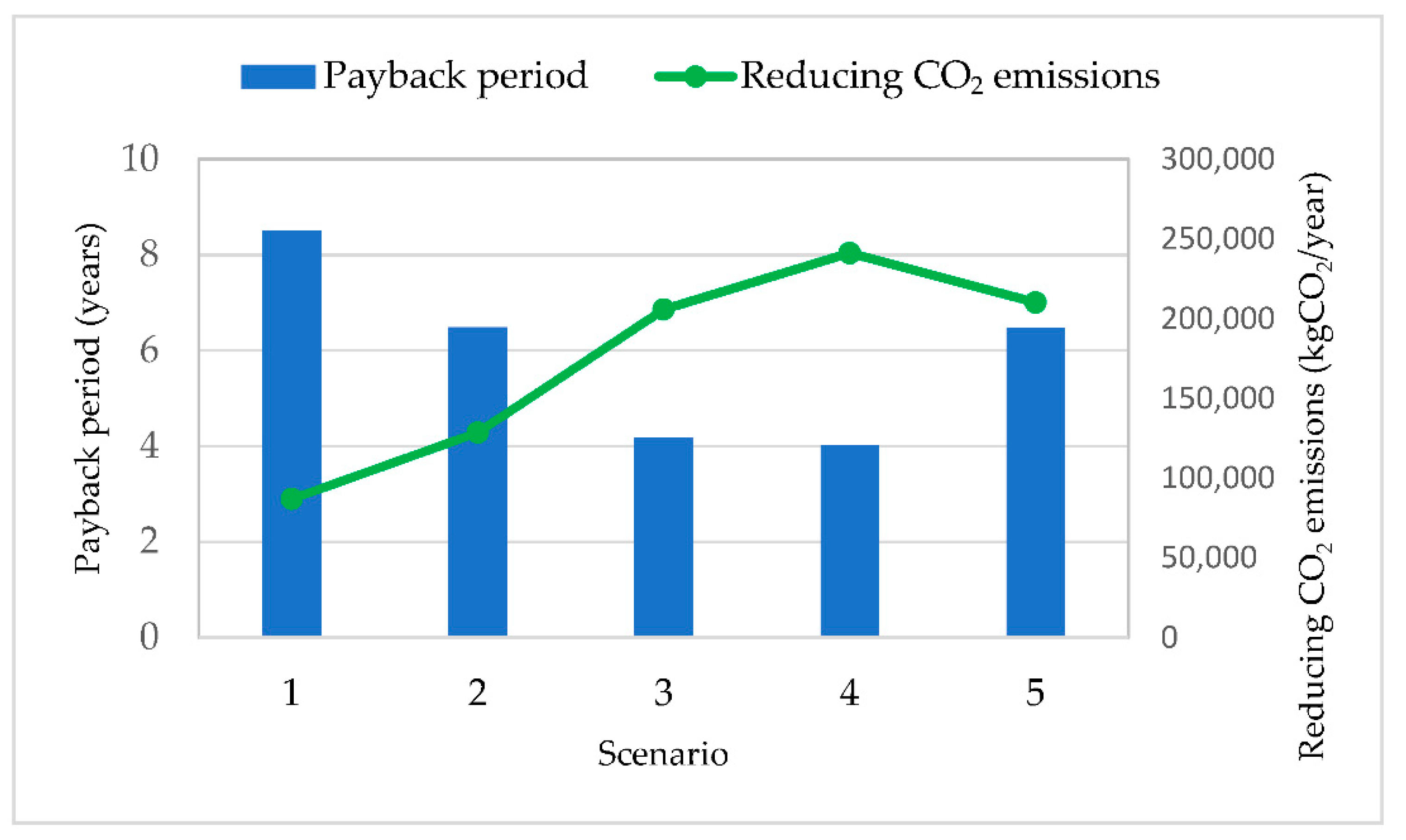
Figure 28 comparatively shows all the scenarios analyzed in terms of the payback period and the reduction in carbon dioxide emissions. The economic and environmental viability of cogeneration and trigeneration solutions can be easily seen in all scenarios. Obviously, the heat demand and the annual time of this demand are the main factors that influence the profitability of cogeneration solutions.
Of all the scenarios analyzed, Scenario 4 and Scenario 5 can be considered as possible solutions to be implemented. Due to the variable nature of heat demand, there is a need for heat storage, as well as the fragmentation of power, in several cogeneration units to increase the operational flexibility of these units.
Scenario 4 is characterized as the optimal economic option for the current energy demand profiles. This scenario ensures the highest values of heat and electricity production, respectively, but also the shortest payback period on investment. In addition, the reduction in carbon dioxide emissions has the greatest value in this scenario.
In Scenario 5, there is a thermal power reserve installed in the second CHP unit (the higher power unit); therefore, the annual operating time of this CHP unit will increase with the expansion in drug production and, implicitly, the payback period on investment will reduce.
6. Conclusions
Current research on the transition to carbon-free energy generation are dominated by renewable energy solutions; however, the continued use of natural gas with the aid of energy efficient technologies, such as cogeneration, seems to be one of the solutions for transitioning to a decarbonized energy system.
The proper sizing and selection of equipment is the most important factor for the success of any cogeneration project. If the selection is incorrect, the CHP system will not properly meet the energy demand or the expected payback period.
The main issues investigated by us in this case study were the variation in heat and electricity demands, and the flattening of the load duration curve for the heat demand. Thus, the heat demand was analyzed in detail and with high accuracy to identify the hourly, daily, weekly, monthly, and annual load profiles. The main purpose of integrating heat storage is the takeover of load variations and to increase the flexibility of the cogeneration plant. A heat storage system will allow a cogeneration unit to work continuously and, consequently, avoid repeated startups and stops that may harm it.
The oversizing of a cogeneration system compared with the consumption needs of an analyzed meter can negatively influence the economic viability of cogeneration and trigeneration projects. If the power of the CHP plant exceeds the consumption needs of the site, the surplus electricity will be delivered to the public electricity network, usually at a much lower rate than the purchase. On the other hand, if the thermal power in cogeneration exceeds the consumption needs, the resulting excess heat will usually be discharged into the atmosphere, as a lost amount of heat. In both cases, the energy savings achieved are not as expected, and the payback period of the cogeneration project increases accordingly.
A major economic incentive for the application of cogeneration technology is the reduction in operating costs by generating electricity at a lower cost than the cost of purchase from the local electricity supplier; therefore, the application of cogeneration can be viable if there is a significant difference between the cost of natural gas and the cost of electricity purchased from the public network. An approximate 1:3 ratio between the cost of natural gas and the cost of electricity was considered in this study. Electricity is significantly more expensive than natural gas, and the viability of cogeneration applications is therefore much more sensitive to changes in the unit price of electricity purchased from the public network.
The results of this study demonstrate the economic and technical viability of the proposed cogeneration and trigeneration solutions. For the values of the electricity and natural gas prices at the time of the analysis (2021), Scenario 4 is characterized as the optimal economical and technical option for the current consumption situation, as it ensures the highest values of heat and electricity production, and the shortest investment payback period (5.06 years). Compared with the separate generation of heat and power, we highlight a primary energy saving of 25.35% and a reduction in CO2 emissions of 241,138 kg CO2/year.


