Article

Process-Product Interdependencies in Lamination of Electrodes and Separators for Lithium-Ion Batteries

1
Institute of Machine Tools and Production Technology, Technische Universität Braunschweig, 38106 Braunschweig, Germany
2
Battery LabFactory Braunschweig, Technische Universität Braunschweig, 38106 Braunschweig, Germany
*
Author to whom correspondence should be addressed.
Energies 2022, 15(7), 2670; https://doi.org/10.3390/en15072670
Submission received: 10 March 2022 / Revised: 31 March 2022 / Accepted: 4 April 2022 / Published: 6 April 2022
(This article belongs to the Special Issue Particle Design and Processing for Battery Production)

Abstract

:
In today’s cell production, the focus lies on maximizing productivity while maintaining product quality. To achieve this, the lamination of electrode and separator is one key process technology, as it bonds the electrode and separator to form mechanically resilient intermediate products. These mechanically resilient intermediates are necessary to enable high throughput processes. Although the lamination process has significant effects on the electrochemical performance of battery cells, it has not been sufficiently researched with regard to its process-product interdependencies. Therefore, this paper addresses the investigation of these interdependencies and proposes three characterization methods (grey scale analysis, high potential tests, electrochemical cycling and C-rate tests). The results of the three methods show that the lamination process with its process parameters (lamination temperature, lamination pressure and material feed rate) has an influence on both the properties of the intermediate product and the cell properties. In conclusion, the knowledge of the process-product interdependencies is essential in order to utilize the advantages of lamination integrated into the process chain and consequently achieve quality-assured cell production.

1. Introduction

1.1. Challenges in Lithium-Ion Battery Cell Production

The importance of electrical storage systems is increasingly strong due to the emerging need to power mobile machines and vehicles sustainably, as well as to use renewable energies flexibly [1]. Especially in the field of electric mobility, the large format lithium-ion battery cell (LIB) is the key technology due to its high performance, energy density, cycling stability and low self-discharge compared to other technologies [2,3]. Owing to the expensive raw materials and complex and multi-stage manufacturing, the LIB accounts for 30–40% of the value-added shares of a battery electric vehicle [4]. In order to establish battery-electric vehicles on the market in the long term, costs must be reduced, and at the same time, the performance of the LIB must be further increased to compete with conventional drives [5]. Both the costs and performance of the LIB are significantly influenced by cell production [6,7]. In cell production, maximizing productivity while maintaining product quality is crucial for increasing profitability and sustainability [8]. However, maximizing productivity while ensuring product quality, e.g., by high-throughput processes, requires two essential conditions. First, raw materials and intermediates need to be resilient both chemically (e.g., to the process atmosphere) and mechanically (e.g., to tensile and compressive stresses) to withstand process-immanent loads. Second, a production monitoring system is required that is capable of inline determination of the relevant process and product properties based on suitable sensors [9]. In this paper, we address these two aspects by discussing the production of resilient intermediates by means of lamination on the one hand and by introducing the linkage of inline and offline measured process- and product- properties on the other hand.
In the lamination process, electrodes and separator are adhesively bonded over their entire surface to form a mechanically and chemically stable composite for further processing. This bonding of electrodes and separator is a new process in current battery cell manufacturing, as traditionally the electrodes and separator are not joined prior to the stacking process step. However, in current cell manufacturing, stacking emerges as a bottleneck in terms of productivity, since the alternating stacking of anode, separator and cathode is a time-consuming task [8]. The high time-consumption results from numerous non-value-adding periods in the multitude of handling steps and a low handling speed in order to not damage the sensitive materials [10]. In addition, cross-contamination between anodes and cathodes must be avoided, which is why the handling systems have a complex redundant design. Both damage and contamination of electrodes and separators lowers electrochemical performance and cycle life and can be the cause of thermal runaway of the LIB. Due to the aforementioned disadvantages of the conventional stacking process, continuous high-throughput stacking processes are currently investigated, which promise an increase in process speed, but at the same time, imply higher loads to the electrodes and the separator [11]. A lamination process that precedes the stacking process combines electrodes and separator into one single resilient intermediates and, therefore, fewer handling steps are necessary to produce a cell stack. Furthermore, lamination reduces the risk of cross-contamination and is itself a continuous roll-to-roll process with a high process speed. As a result, lamination is an essential enabler for high-throughput production and can even contribute to an improvement of the electrochemical properties of a LIB [12,13].

1.2. Lamination Process in Battery Cell Production

In the lamination process, the separator is laminated onto the electrode so that a material bond is formed between the material interfaces. The bonding is created by thermal softening of a binder, which is usually located on the separator surface, and the application of force to the electrode–separator composite. In general, a line load is applied to the electrode–separator composite by a rotating pair of rollers or by a revolving metal belt. The necessary thermal energy can be applied at the same time as the force, e.g., via temperature-controlled rollers, or separately from the force via a preheating zone. The electrodes and separators can be fed into the lamination process as web material or discretely. A combination of web-based feeding, for example, of the separator, and feeding of cut-to-size electrodes is possible.
Figure 1 schematically shows a lamination process with a discrete material feed of the electrodes (1), web-bound feed of the separator (2) and a separate preheating zone (3). Before lamination, the electrode–separator composite is covered on both sides with a protective film (4), which is removed from the electrode–separator laminate after lamination. This protective film prevents the separator from sticking to machine parts during the lamination process. The lamination rollers (5) are located immediately behind the preheating zone. Depending on the structure of the electrode–separator composite, different laminates can be produced. On the one hand, the anode or cathode can be laminated with a separator from one or both sides. On the other hand, so-called mono-cells can be produced in the lamination process. These mono-cells are laminated electrode–separator–electrode–separator structures.
For the homogeneous, reproducible and non-destructive application of a continuous separator web onto a discrete electrode, six process parameters are key. The first and second are the web tension and the deposition accuracy during product insertion into the process. The web tension of the separator can be adjusted with a tension control dancing system, as in the established Z-fold process. An active dancer, which can be freely parameterized and has position and torque control, is purposeful here. The position of the web edge is determined by an optical measuring unit and adjusted by a rotatable deflection roller. The electrodes are placed precisely with a handling system to ensure that the single sheets overlap in the subsequent cell stack. The insufficient overlap would lead to significant losses in the electrochemical performance of the battery cell, just as in stacking without lamination. To achieve a high deposition accuracy, the position of the electrodes in the pick-up position is usually recorded with a high-resolution, telecentric camera system in the bright field of collimated background illumination, and from this, a correction vector for ideal deposition on the continuous separator belt is determined. This position correction is also used when processing single sheets for compound manufacturing. In addition to the mentioned web tension and deposition accuracy control, further quality measurement techniques can be transferred from the conventional stacking process. In particular, the input inspection of the electrodes and separators can be directly adopted for the lamination process. After cutting, the size accuracy, edge quality, surface condition, contamination and moisture content of the electrodes and separator can be checked using methods already implemented [14,15].
During the lamination process itself, the four parameters—material feed rate (i), roll gap (ii), contact pressure on the laminate (iii) and process temperature (iv)—complete the essential parameters influencing the product properties of the manufactured laminates [16]. These process parameters can be measured and controlled with established sensor technology. The material feed rate (i) is defined by the roll rotational speed and can therefore be monitored with rotary encoders. Here it is important to set a slip-free operation between the rollers, otherwise, the separator may wrinkle or be damaged. Consequently, a coupled drive of the rollers via a belt drive has become established industrially so that slippage is prevented by the mechanical design. The roll gap (ii) is also adjusted mechanically. Limited by mechanical stops, active opening and closing are possible depending on the roll materials used. In most cases, no static roll gap is set, but rather the opening width is adapted to the process operation via force control. When using rubberized and soft rolls, active roll gap control is thus not required since a smooth transition in force adjustment occurs when the electrode edges enter the roll gap. If hardened rolls are used, damage to the electrode edge would be high, with the result that active gap control may be required. In addition to the roll gap, the contact pressure of the rolls (iii) has a mechanical effect on the electrodes and separator and is, therefore, an important parameter for ensuring sufficient adhesion and preventing damage. The contact pressure of the rolls is generated by a pneumatic or hydraulic system and can be measured either from the pressure values of the pressure medium used or directly at the rolls via integrated load cells. Besides the contact pressure, for sufficient adhesion, a process temperature (iv) is required that causes the binder to soften. To achieve a defined temperature range in which the binder softens but is not irreversibly decomposed, the temperature in the preheating zones and the rollers is measured by integrated contact sensors with short response times. The surface temperature of the laminate is measured by non-contact pyrometers. The challenge with this measurement is the deduction of the temperature between the electrodes and the separator since the contact area between the separator and electrode cannot be measured. Thus, control and regulation of this process parameter are not possible by direct measurement.

1.3. Research Scope

Since the lamination of electrode and separator is a novel process step in the manufacturing of LIB, the knowledge regarding the interactions between the presented six process parameters and the electrochemical properties of the manufactured battery cell is still desiderate. Establishing these interactions is challenging because numerous other processes whose parameters also influence the battery cell properties follow the lamination process. A direct link between the lamination process and electrochemical cell performance is therefore not trivial. For this reason, intermediate properties of the electrode–separator laminates that can be properly measured should first be correlated with the lamination process parameters, and then these intermediate properties can be assigned to the electrochemical performance of the battery cell. Consequently, the intermediate product properties create the link between process parameters and cell properties. Furthermore, the measured intermediate product properties would enable inline capable process control, which provides quality-assured production of battery cells made of laminates.
The paper presented here proposes measurement parameters and methods for the novel lamination process to determine the relevant intermediate product properties. In comprehensive experimental studies, laminates were manufactured under systematic variation of the presented process parameters and characterized regarding their intermediate product properties. Furthermore, laminates were processed into cells in a qualified and standardized cell manufacturing process, and the cells were electrochemically characterized to show the effect that improperly selected lamination process parameters can have on cell performance. In conclusion, this paper provides suitable process parameter values for the lamination process and, at the same time, introduces measurement concepts. These concepts provide the basis to realize a detailed analysis of process-product interactions in the future.

2. Materials and Methods

2.1. Materials

The active material of the cathodes used for the experiments is nickel–cobalt–manganese oxide NMC-622 with a discharge capacity of 190 mAh g−1 (BASF SE, Ludwigshafen, Germany). Polyvinylidene fluoride (PVdF) as a binder (Solvay S.A., Brussels, Belgium) and carbon black C65 (Imerys Graphite & Carbon Belgium SA, Willebroek, Belgium) and SFG6L (Imerys Graphite & Carbon Switzerland Ltd., Bodio, Switzerland) as a conductive were also added to the dry cathode material mass. The active material accounts for 93 wt.% of the dry raw material mass while the binder and conductive carbon blacks account for 4 wt.% and 3 wt.%, respectively. N-methyl-2-pyrroldidone (NMP) was used as solvent in the ratio of 70% dry mass to 30% solvent. The resulting cathode paste was coated as 60 µm thick layers on both sides on a 10 µm thick hydro aluminum foil, and afterwards dried and calendered. The areal mass of the active material of the cathode measures 31.11 mg cm−2 (standard deviation: 0.14 mg cm−2) and the cathode density is 3.2 g cm−3. The cathodes were then cut into 65 × 45 mm2 electrodes in a laser cutting process.
The anode is composed of 93 wt.% syntetic graphite with a discharge capacity of 385 mAh g−1 (the material supplier cannot be named for reasons of confidentiality) as active material, 1.33 wt.% carboxymethyl cellulose CMC (DOW Europe GmbH, Horgen, Switzerland) and 2.67 wt.% styrene-butadiene SBR (ZEON EUROPE GmbH, Düsseldorf, Germany) as the binder, and 2 wt.% conductive carbon black C65 (Imerys Graphite & Carbon Belgium SA, Willebroek, Belgium) and 1 wt.% conductive carbon black SFG6L (Imerys Graphite & Carbon Switzerland Ltd., Bodio, Switzerland) as conductive additives. Distilled water was mixed into the dry raw material in a ratio of 50% solids to 50% solvent. The anode paste, which consists of 50% raw material and 50% distilled water as a solvent, was coated on both sides of a 10 µm thick copper foil. After subsequent drying and calendering, the anode thickness measured approximately 120 µm. The areal mass of the active material of the anode measures 16.05 mg cm−2 (standard deviation: 0.16 mg cm−2) and the anode density is 1.5 g cm−3. The resulting N/P ratio equals 1.25. Similar to the cathodes, discrete electrodes with dimensions of 70 × 50 mm2 were cut out of the anode material using a laser cutting process.
Three different separators were used for the investigations. For reasons of confidentiality, the clear names of the separators are not used; instead, they are referred to as separator A, B and C. All three separators can be laminated by coating the surfaces with polyvinylidene fluoride (PVdF). For separators B and C, the PVdF was previously applied to aluminum oxide particles with dimensions in the submicrometre range and these particles were then applied to the separator surface. Separator A is a 23 µm thick nonwoven separator impregnated with ceramic particles. The base material of the separator is polyester (PET) with a theoretical porosity of 56%. Its air permeability (Gurley value) amounts 100 s for 100 mL and its thermal shrinkage at 200 °C is less than 1% after 1 h exposure. Separator B is a membrane-based monolayer separator made out of polyethylene (PE) with a thickness of 23.5 µm and an air permeability (Gurley value) of 160 s for 100 mL. The manufacturer has neither provided any information about the theoretical porosity nor the thermal shrinkage. Separators C is a membrane-based trilayer separator whose inner layer is made of polyethylene (PE) and the two surrounding layers of polypropylene (PP). The nominal thickness of the separator is 20 µm with a calculated porosity of 46%. The air permeability (Gurley value) given by the manufacturer is 240 s for 100 mL and the thermal shrinkage at 105 °C is 1.8% after 1 h exposure.
The electrolyte used for all electrochemical tests consists of a one-molar solution of lithium hexafluorophosphate (LiPF6) dissolved in 30 wt.% ethylene carbonate (EC) and 70 wt.% ethyl methyl carbonate (EMC). An additional 2 wt.% vinyl chloride (VC) was added to the solution to improve cycle efficiency.
A pouch foil was chosen as the housing material for the battery cells produced with the above-mentioned electrodes, separator and electrolyte. The pouch foil is a multi-layer composite with a polyethylene terephthalate layer, a layer of oriented nylon, an aluminum layer surrounded by a protective layer resistant to hydrogen fluoride, and a layer of polypropylene.

2.2. Methods

Three different methods for the characterization of electrode–separator laminates were used in this paper: greyscale analysis of the surface of the electrode–separator laminates after lamination, high-potential test on laminated electrode–separator composites and electrochemical measurements of battery cells made with electrode–separator laminates.
For all electrode–separator laminates produced in this paper, a lamination system from Polatek SL-Laminiertechnik GmbH was used. The system was equipped with a heated pair of rollers without separate preheating elements. The lamination temperature was varied in the range from 60 °C to 140 °C, while contact force of the rollers ranged from 0.66 kN to 2 kN. In one system configuration, the upper and lower roller had an aluminium core with a non-stick coating, in another configuration, the upper roller had an aluminum core with a fluoroelastomer coating with a Shore hardness of 70 Sh and the lower roller had an aluminum core with non-stick coating. With the first configuration, higher contact pressures of up to 30 Nmm−2 can be achieved due to the rigid rollers, while the pressure of the second configuration reaches a maximum of 7 Nmm−2.
The feeding rate was held constant at 1 m min−1. All lamination tests were performed in a dry room atmosphere at 20 °C room temperature and −45 °C dew point inside the dry room of the Battery LabFactory Braunschweig (Research Centre of the Technische Universität Braunschweig). The investigations shown in this publication are focused on the lamination of cathodes. However, the production of anode-separator lamination is also possible (see [17]).

2.2.1. Grey Scale Analysis

The objective of the grey scale analysis is to show a correlation between process parameters of lamination, such as lamination temperature or lamination pressure, and the grey scale value of the laminate surface. Due to the optical transparency of the thin separators, the comparatively dark electrode surfaces underneath the separator stand out, so that the electrode–separator-laminate surface appears darker than the separator surface itself. If the optical transparency of the separators is changed, e.g., by the influence of temperature or pressure, the measurable grey value of the electrode–separator-laminate surface can also change. If the relationship between process parameters and the resulting product properties of the laminates is known and a link between the grey value and process parameters could be established, i.e., a specific grey value could be assigned to certain temperature-pressure combinations.
Consequently, conclusions can be drawn about the expected product properties of the laminates by measuring the grey value. Both the mechanical adhesion between electrode and separator or the resulting electrochemical properties of the laminates can represent essential product properties. The approach of grey value analysis can thus be a feasible approach for process monitoring of lamination or product control of the laminates.
For the grey scale analysis of the electrode–separator laminates, the surfaces of the produced laminates were photographed using a camera system under the same exposure conditions each time. The resulting monochromatic images allowed the analysis of the average grey values of the surfaces of the produced laminates. The camera system of The Imaging Source Europe GmbH consists of a monochrome camera with 1-inch Sony CMOS IMX183 sensor, rolling shutter and a resolution of 5472 × 3648 (20 megapixels) as well as an object with 16 mm focal length.

2.2.2. High-Potential Test

The high-potential test comprehends the application of high-voltage stress to identify electrical discharges within insulation layers. Although it is usually applied for the inspection of electrical equipment [18], this method has been presented by Hoffmann et al. [19] as a quality control method in battery production to identify separator failures. Defects such as particle contamination and holes may generate air-filled voids within the dielectric separator material, leading, locally, to a lower dielectric constant. This weakens the performance of the separators’ insulation layer and may lead to breakdowns at certain voltages. The experiments described in Hoffmann et al. [19] presented, as shown in Figure 2, four behaviors: (a) no discharge, (b) discharge with full recovery, (c) discharge with partial recovery, and (d) discharge without recovery.
A separator passes the high-potential quality control when the voltage curve remains stable at the applied voltage, as shown in Figure 2a. In faulty separators, the insulation layer is affected and the test results present discharges, as shown in Figure 2b–d. In some cases, the defect is responsible for a transient and local discharge, without affecting the entire stack performance, so the voltage curve recovers after breakdown (Figure 2b,c). Discharges without recovery (Figure 2d) were observed when the defect damages the insulation performance of the entire stack.
In this work, we reproduced the methodology setup and parameters recommendations from Hoffmann et al. [19] to study the effects of different lamination parameters with the high-potential test. The necessary material and equipment include a cell stack, pressure chamber and current meter (Keysight B2985A). As recommended by Hoffmann et al. [19], the cell stack under test was pressed with 0.3 Nmm−2 and a voltage of 400 V was applied for 1 s.
All tests are carried out in the dry room of the Battery LabFactory Braunschweig at a room temperature of 20 °C and a dew point of −45 °C, as a change in atmospheric conditions and the resulting variation of the conductivity of the air can also influence the results of the high potential measurements.

2.2.3. Measurements of Electrochemical Cell Properties

To investigate the influence of lamination process parameters on the electrochemical properties of electrode–separator laminates, laboratory cells—consisting of one anode and one cathode–separator laminate—were produced. Therefore, anodes and cathode–separator laminates were stacked to one compartment cells within the dry room of the Battery LabFactory Braunschweig. After a drying process at 80 °C and 50 mbar ambient pressure for 16 h in a vacuum oven to reduce the residual water, the cell stacks—enclosed in pouch foil bags—were transferred to a glove box (argon atmosphere, water content < 0.1 ppm; oxygen content < 0.1 ppm) and filled with 1 mL electrolyte before a final sealing process closed the last side of the pouch foil bags at an evacuation pressure of 100 mbar.
After a 24-h rest time, during which the microporous cell materials could be completely wetted with electrolyte, all cells were subjected to a formation procedure and aging tests. While formation, all cells were charged (CCCV) at C/10 and discharged (CC) at C/2 in the first and second cycles. The lower cutoff voltage was set to 2.9 V and the upper cutoff voltage was set to 4.2 V. In a third cycle, the nominal charge and discharge capacity of all cells was determined at C/10. Subsequent self-discharge tests at the beginning and the end of an 8-day resting period were conducted. During the aging tests, all cells were charged and discharged at 2C and the fast-charge ability was determined after 7, 74, 191 and 300 cycles by applying a C-rate test (1C up to 5C). All C-rate tests are preceded by a capacity test at 1/10C, a self-discharge test and internal resistance measurement. During the beginning of the C-rate tests, the cells may regenerate and thus change their C-rate performance in comparison to the behavior during the cycling. The procedure used for formation and cycling is established at the Battery LabFactory Braunschweig.

3. Results and Discussion

3.1. Grey Scale Analysis

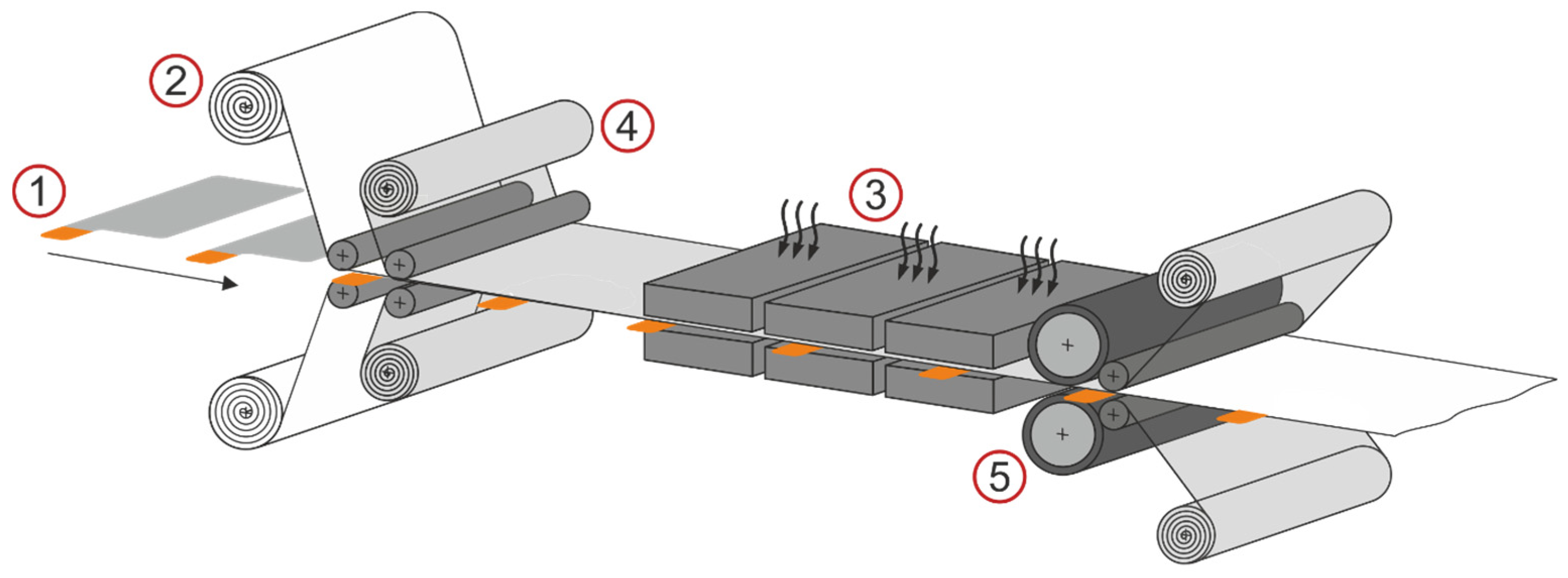
To investigate the relationship between the optical surface properties of cathode–separator laminates and the process parameters of the lamination process (lamination pressure and temperature), a total of 72 laminates were subjected to a grey scale analysis. Ten parameter pairings were examined for a total of three separators, a nonwoven separator (separator A), a membrane-based monolayer (separator B) and a membrane-based trilayer (separator C), whose structural design is different. The sample size for each parameter pairing was three. The roller configuration of the lamination system consists of an upper roller with an aluminum core with a fluoroelastomer coating (hardness of 70 Sh) and a lower roller with an aluminum core with a non-stick coating. The process parameters varied were the lamination temperature in the range of 60 °C to 150 °C and the lamination pressure in the range of 4 Nmm−2 to 7 Nmm−2. Figure 3 shows the average grey values of the laminated surfaces and the corresponding standard deviations of the three separators for the respective parameter pairings. Table A1 in Appendix A shows the numerical values.
For all electrode–separator composites investigated, the grey values differ between the three types of separator, regardless of the process parameters. Electrode separator laminates produced with separator A (nonwoven separator impregnated with ceramic particles) have an average grey value of approximately 180 and contact pressure and temperature have no significant influence on the grey value in the process parameter range investigated. The pressure and temperature range in which separator A can be processed according to this grey scale value investigation without a change in the optical properties and thus possible damage to the separator extends from 60 °C up to 150 °C for all three tested pressure levels (see red box in Figure 3).
Separator B (membrane-based monolayer) was stable in terms of its optical transparency in the temperature range from 60 °C to 130 °C and achieved an average grey value of approximately 160 at all three pressure levels. Only at temperatures above 130 °C did the measured grey value of the separator surface drop to values below 140. The grey scale images in Figure 3 illustrate this observation. While there was no clear difference between the grey scale images at 100 °C (a) and 130 °C (b), the decrease of the grey value at 150 °C (c) is clearly visible in the grey scale images. The linear patterns (PVdF coating) also became increasingly distinct as the temperature rises. The separator became optically more transparent due to thermal stress and the dark cathode surface was more clearly visible, which results in a reduction of the grey value. Based on the results of this grey value analysis, the temperature range from 60 °C to 130 °C can be considered suitable for separator B for all three pressure levels (see red box in Figure 3). It should be noted that it is important to verify that the mechanical adhesion between separator and electrode is also sufficient in the entire temperature range from 60 °C to 130 °C and that there are no limitations on the electrochemical properties of the electrode–separator laminates in this range.
The largest temperature-dependent differences in grey value were measured for separator C (membrane-based trilayer). At a lamination temperature of 60 °C, the grey value for all three pressure levels is approximately 140. At this temperature, no material bond between separator and cathode was formed, and thus, no laminate was produced. Above a temperature of 80 °C, electrode–separator laminates with sufficient bonding between cathode and separator could be produced. The grey value reaches 120 at a lamination temperature of 80 °C and remains constant at this value until a temperature of 120 °C. Starting at 130 °C, the measured grey value of the laminate surface drops significantly and reaches its minimum value of approximately 85 at 150 °C and a lamination pressure of 5.5 Nmm−2. With regard to the different pressure levels, it is evident that the lamination pressure has an effect on the grey value for separator C from temperatures above 130 °C, although no systematic correlations are evident from the data collected.
The results of the grey value measurements allow an assignment of the process parameters lamination temperature to surface grey values of different separators only partially or only in certain process parameter ranges. It could not be proven that the lamination pressure has an effect on the optical transparency of laminated separators.
While it was not possible for separator A to assign certain lamination temperatures to certain grey values, an assignment can be made to some extent for separators B and C. With separator B, the decrease in the grey value from 130 °C also represents the beginning of the thermally-induced destruction of the separator. Here, the decrease in grey value is a useful indicator of the limit of the lamination process range. With regards to separator C, this thermal destruction of the separator already begins at a lamination temperature of 120 °C and is also indicated by a clear decrease in the grey value. In addition, the grey value at 60 °C for separator C can be attributed to incomplete lamination of the electrode and separator, as it was not possible to create a material bond between the two joining partners, electrode and separator at this lamination temperature. As a result, a grey value of around 120 can be used as a desirable value for Separator C.
Furthermore, the grey scale measurement results show that by measuring the optical transparency of membrane-based laminable separators, it is possible to indirectly determine the lamination temperature and to analyse whether lamination was performed within a certain temperature range (see red boxes in Figure 3). Further investigation is needed to show whether similar relationships can also be derived for other process parameters such as the lamination pressure or the feed rate.
The relatively short measuring time of the grey scale value measurements allows the use as an inline-capable method for the analysis of electrode–separator laminates and can thus be an option for cost-effective process monitoring that can also be adapted to existing lamination systems. Moreover, the grey value measurement could then have the potential to be used long term as a metrology tool to optimize the output material and the process in large-scale battery production.

3.2. High-Potential Test

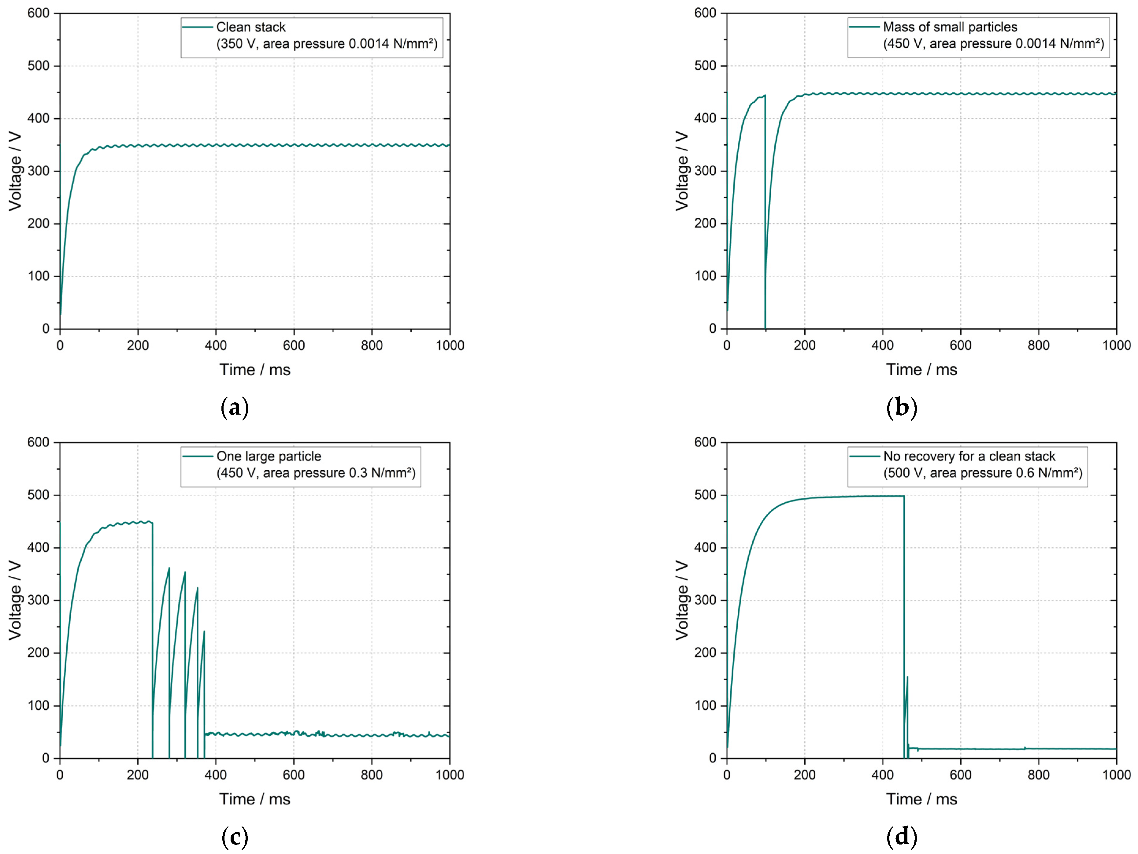
Different from the previous method, high-potential tests were carried out to investigate the influence of three feed rates (1.0 m min−1, 0.5 m min−1, 0.1 m min−1) during lamination on the electrical resistance of the separator. For that, separators B (membrane-based monolayer) and C (membrane-based trilayer) were examined. Since the grey scale results for these separators were not stable at high temperatures and pressure, the lamination pressure and temperature were kept constant at 5.5 Nmm−2 and 100 °C, respectively. The separators were laminated on cathodes and processed into 1-compartment cell stacks consisting of one anode and one cathode–separator laminate. A non-laminated cell stack was used as a baseline for each separator and the roller configuration of the lamination system is the same as for the grey scale experiments.
Results of the high potential test can be seen in Figure 4, where the measured voltage for each cell stack is plotted over the measurement period of 1 s. The initial rise in voltage in the first 100 ms results from the test setup. For clarity, a section of the voltage range from 0 V to 40 V is shown enlarged.
In the reference setup, separator B showed the expected voltage curve over the one-second measurement period, maintaining the specified voltage of 400 V without discharges. The same behavior was observed at material feed rates of 1.0 m min−1 and 0.5 m min−1. At a feed rate of 0.1 m min−1, the separator B withstood a voltage of approximately 32 V for the entire test duration. The reference cell stack produced with separator C presented the same expected voltage curve as the separator B reference. At a feed rate of 1.0 m min−1 during lamination, separator C could not maintain the desired voltage of 400 V and the results showed a voltage of about 14 V. At a material feed rate of 0.5 m min−1, separator C could withstand 12 V. At a 0.1 m min−1 feed rate, the maintained voltage was close to zero (approximately 0.15 V). This behavior of withstanding lower voltages was not observed in the previous high potential experiments done by Hoffmann et al. [19].
In cell operations, the expected voltage for the electrodes used in this work was approximately 3.6 V. Consequently, cell failure, e.g., due to short-circuit, would not be expected when using the laminates produced with material feed rates of 1.0 m min−1 and 0.5 m min−1. For separator B, an immediate short-circuit would not be expected to occur even for a material feed rate of 0.1 m min−1 as the separator can withstand 32 V constantly. However, the high-potential results for separator C showed a significant reduction in the electrical resistance at the slower feed rate of 0.1 m min−1 and a short-circuit in cell operation is, therefore, expected.
Overall, high potential tests confirm to be a viable method to study optimal lamination process parameters since it allows damage-free analysis of the separator electrical resistance. The results of the presented investigation show that the material feed rate during lamination considerably affects the condition of the separator as an electrical resistor. Moreover, the resistance with respect to the adjustment of the material feed varies for each separator type with separator C (membrane-based trilayer) presenting poorer resistance than separator B (membrane-based monolayer) at low feed rates. Although lower voltages will probably not present short-circuits for an operation under 3.6 V, the longevity of the separator during several charging and discharging processes as well as the unexpected behavior of the voltage curve, especially for separator C, needs to be thoroughly investigated and verified. For this purpose, the electrical chemical properties of a cell produced with separator C will be investigated in the next section.

3.3. Measurements of Electrochemical Cell Properties

As part of the ageing tests of one-compartment cells consisting of a cathode laminated with separator C (membrane-based trilayer separator) and an anode, five cells were produced for each of the nine parameter pairings. For this purpose, the three lamination temperatures 80 °C, 100 °C and 120 °C were combined (full factorial) with three lamination pressures 10 Nmm−2, 20 Nmm−2 and 30 Nmm−2. An upper and lower roller with an aluminum core with non-stick coating was chosen as the roller configuration of the lamination system. As a reference, cells were used that were manufactured with the same membrane-based trilayer separator, but the separator was not laminated to the cathode. 
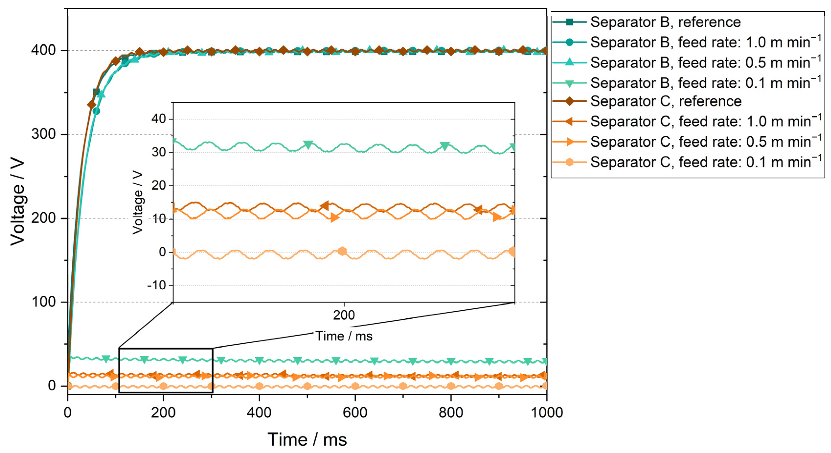
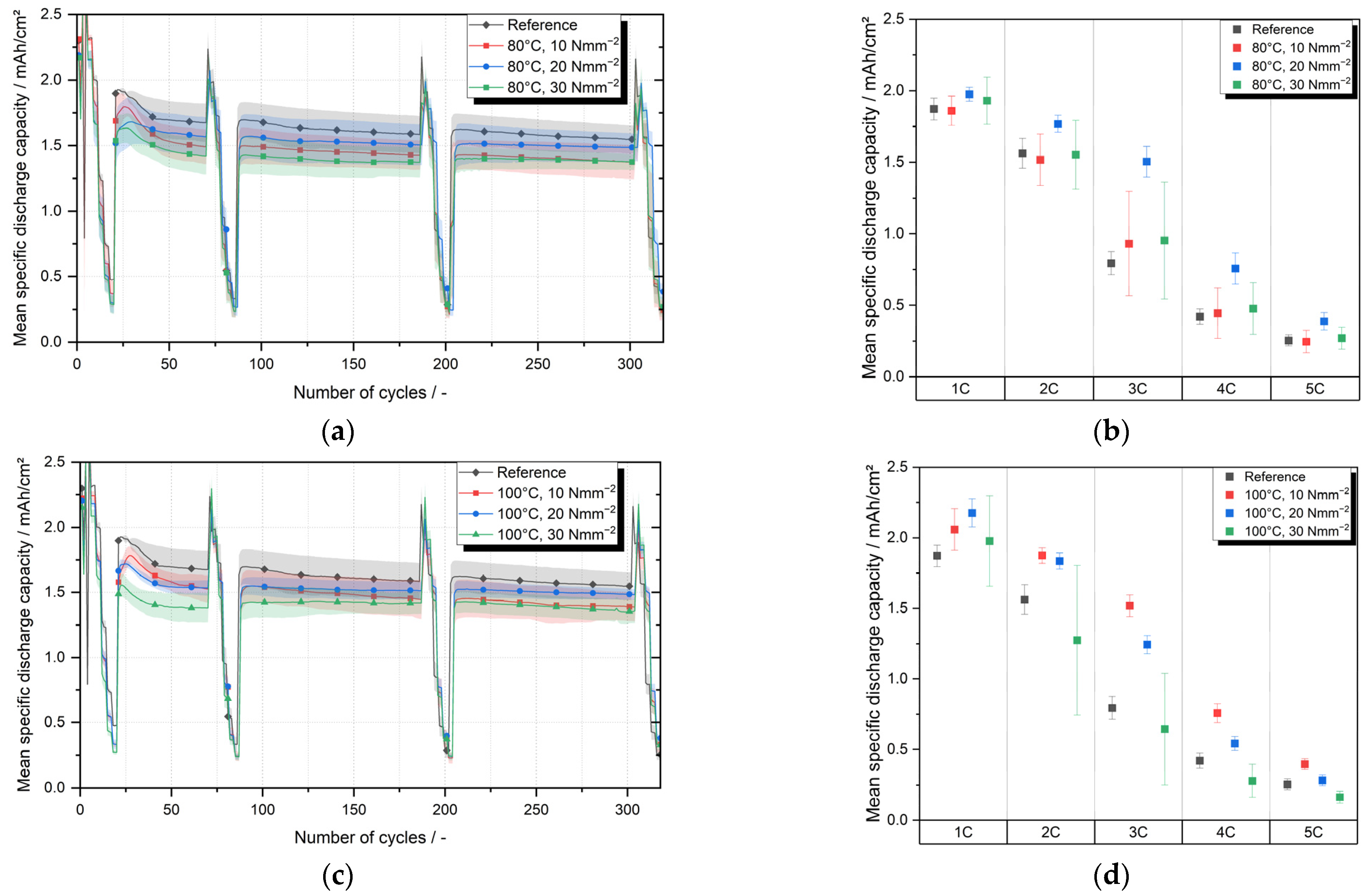
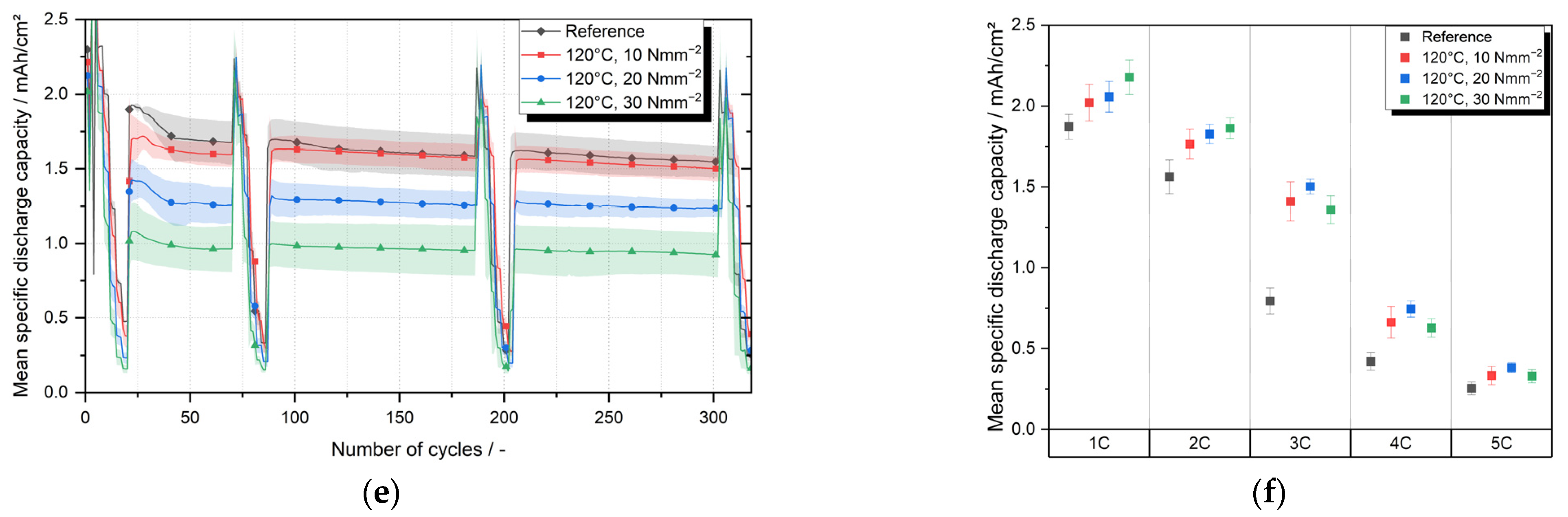
Figure 5a,c,e shows the mean specific discharge capacities over 300 cycles of the cells whose cathode–separator laminates were laminated at 80 °C, 100 °C and 120 °C. Table 1 lists the average discharge capacities after 30 cycles (after the first C-rate test) and after 300 cycles.
After 300 cycles, the laminates laminated at 80 °C and with 10 Nmm−2 reach an average specific discharge capacity of 1.373 mAh cm−2 and thus 89% of the discharge capacity of the reference after 300 cycles. The laminates produced at 80 °C with a lamination pressure of 20 Nmm−2 and 30 Nmm−2 reached a discharge capacity of 1.487 mAh cm−2 and 1.375 mAh cm−2, respectively, and thus 96% and also 89% of the discharge capacity of the reference. At a lamination temperature of 100 °C the average specific discharge capacity after 300 cycles reaches 1.392 mAh cm−2 or 90% of the reference value for a lamination pressure of 10 Nmm−2, 1.485 mAh cm−2 or 96% of the reference value for a lamination pressure of 20 Nmm−2 and 1.350 mAh cm−2 or 87% for a lamination pressure of 30 Nmm−2. The average specific discharge capacity for cells with cathode–separator laminates produces at a lamination temperature of 120 °C differed considerably for the three pressure levels investigated. While discharge capacity for the lamination pressure of 10 Nmm−2 was 1.500 mAh cm−2 and thus 97% of the reference value, the average specific discharge capacities for 20 Nmm−2 and 30 Nmm−2 were 1.235 mAh cm−2 and 0.924 mAh cm−2 respectively. Compared to the reference value, this corresponds to 80% and 60%, respectively.
In order to detect static differences between the data sets, t-tests were carried out between the data set of the reference and the respective data sets of the individual parameter pairs. Prior to all t-tests, all data sets were tested for normal distribution. The evaluation of the t-tests shows that at lamination temperatures of 80 °C and 100 °C in combination with lamination pressures of 10 Nmm−2 and 20 Nmm−2, no significant (significance level α = 5%) differences between the samples is evident. Only at a lamination pressure of 30 Nmm−2 do the measured discharge capacities at 80 °C and 100 °C differ significantly from the discharge capacities of the reference, although these significant differences are marginal. The average specific discharge capacity of cathode–separator laminates processed at a lamination temperature of 120 °C, on the other hand, differs significantly between all three pressure levels tested. While no differences can be statistically proven between the reference and pressure level 10 Nmm−2, the difference between the reference respectively 10 Nmm−2 and the two other lamination pressures, 20 Nmm−2 and 30 Nmm−2, is significant.
The evaluation shows that the lamination parameters temperature and contact pressure can have a significant impact on the discharge capacity of battery cells consisting of laminated cathode and anode. The impact, however, only becomes visible at higher pressures (30 Nmm−2) or high temperatures (120 °C). The reason for this could be a change in the pore structure of the separator due to high pressures or high temperatures during the lamination process. The temperature-related closing of pores and the resulting reduction in the electrode surface area involved in the electrochemical processes can be the cause of the reduced capacity. Further investigations are required to substantiate these assumptions and, if necessary, to identify specific correlations.
It can therefore be stated that the process step of lamination can negatively influence the electrochemical performance of battery cells if the improper process parameters of lamination are selected. The study also showed that if the process parameters are chosen correctly, the cycle stability is not reduced by lamination of the cathode and separator compared to a reference. Extending the parameter study presented by including laminated anodes could be promising, as Frankenberg et al. [17] have shown that laminated anodes can have a positive effect on the cyclic aging of battery cells.
Figure 5b,d,f displaces a detailed view of the C-rate tests performed after 300 cycles. The mean specific discharge capacities and the corresponding standard deviations are shown separately for each parameter pair and each 1C-rate, varying from 1C up to 5C. Compared to the cycling tests, the cells show higher discharge capacities during the C-rate test at 1C. These higher measured discharge capacities result from a regeneration during the C-rate procedure, in which the cells are charged and discharged with 1/10C before the actual C-rate test in order to decouple the C-rate test from the cycling.
Regarding the cells with laminates produced at 80 °C, a significant difference can be observed between the pressure level 20 Nmm−2 and the reference cells for C-rates of 2C, 3C and 4C (see Figure 5b). For all other C-rates tested, there are no significant differences. Likewise, no significant differences between laminated cells and the reference can be seen for the pressure levels 10 Nmm−2 and 30 Nmm−2. At a lamination temperature of 100 °C (see Figure 5d), there is a tendency for the laminated cells to have higher mean discharge capacities, in some cases up to twice as high (see 20 Nmm−2 at 3C), compared to the not laminated reference cells. At 10 Nmm−2 for the C-rates 2C to 5C and at 20 Nmm−2 for the C-rates 2C to 4C, this tendency is also statistically significant. At 30 Nmm−2, a statistically significant difference between reference and laminated cells cannot be proven due to high standard deviations. The discharge capacities of the cells with cathode–separator laminated at 120 °C are significantly better than the reference at 2C, 3C and 4C. At 3C, discharge capacities are almost twice as high (see Figure 5e). At 1C and 5C, an increase in the discharge capacity of the laminated cells cannot be statistically proven with certainty. However, the discharge capacity of the reference tends to be lower than the discharge capacity of the cells with laminated cathode even at these C-rates. As Frankenberg was able to show, the surface resistance is reduced by lamination of the cathode. Whether a variation of the lamination process parameters can influence the surface resistance is not yet known, but it would be a possible explanation for the change in the average discharge capacities during the C-rate tests since the surface resistance is a crucial cell property. In principle, it is suspected that the lamination has improved the ionic conductivity of the separator or the separator-elector-dense interface and thus improved the C-rate performance, particularly at high C-rates. Further research should be conducted to verify that lamination process parameters can influence the surface resistance at the electrode–separator interface.
Overall, trends and often significant differences can be seen that cells with laminated cathode show better discharge capacities in the C-rate tests compared to the non-laminated reference cells. Due to the partly high standard deviations, the significant differences are not verifiable for all lamination temperatures and not for all C-rates.

4. Conclusions and Outlook

Within the scope of this publication, two inline-capable measurement methods were presented and applied to analyze the product properties of electrode–separator laminates. In addition, the results of electrochemical investigations of laminates were discussed in order to derive conclusions on feasible process parameter combinations of the lamination process. By means of grey value measurements, it could be shown that the optical transparency of membrane-based laminable separators changes depending on the lamination temperature. No dependence could be determined for the nonwoven separator investigated. Due to the relatively short measurement time in laboratory tests, grey scale measurements are a potentially inline-capable method for the analysis of electrode–separator laminates. Grey value measurements can be a method for process monitoring that can also be integrated into existing systems at a low cost.
High potential tests have shown that the material feed rate of the lamination process can have a significant impact on the safety of cell operation (risk of short circuits). High potential tests can be used to check electrode–separator laminates before further processing and thus ensure that no failures occur during cell operation, as the insulating property of the separator is an essential prerequisite for the use of electrode–separator laminates in cell operation. In conclusion, the high potential test can be a valuable quality gate for product control of the laminates subsequent to the lamination process. For a broader understanding, future investigations will be extended to other separators and fault cases—especially particle contamination—will be investigated in combination with lamination, as the combination of particles and lamination is particularly critical with regard to the electrical resistance of separators. The influence of other process parameters such as the lamination temperature or the lamination pressure on the electrical resistance of the separator should also be further investigated in order to be able to build up a broad understanding of the influencing factors.
In comprehensive electrochemical investigations, the effects of the lamination temperature and the lamination pressure on the discharge capacity of battery cells produced with cathode–separator laminates could be shown. The effects of the lamination process were evident both in regards to cycle stability and C-rate performance. All cells, including the reference cells, were manufactured with the same separator, therefore, tests are planned with different separators and non-NMC-based cathodes to confirm the universality of the statement that cells with laminated cathodes tend to have better discharge capacities in the C-rate test. Likewise, cells with laminated anode will be investigated to assess the C-rate performance of these laminates as well.
In conclusion, this study highlights that the investigated process parameters of lamination temperature, pressure and material feed rate have a significant impact on the different product properties of the laminates. A profound understanding of the influence of all process parameters of lamination is a fundamental prerequisite for the quality-assured design of the process and essential for the production of high-quality battery cells. The measurement methods presented and the knowledge gained about the process-product interdependencies can contribute to designing and monitoring the lamination process in such a way that laminates with the best possible properties can be produced.

Author Contributions

Conceptualization, R.L., A.F. and S.M.; methodology, R.L. and G.V.S.; validation, R.L., A.F., S.M. and G.V.S.; investigation, R.L., A.F. and G.V.S.; writing—original draft preparation, R.L., A.F., S.M. and G.V.S.; writing—review and editing, R.L., A.F., S.M., G.V.S. and K.D.; visualization, R.L. and G.V.S.; supervision, K.D.; project administration, R.L., G.V.S. and K.D.; funding acquisition, K.D. All authors have read and agreed to the published version of the manuscript.

Funding

This research was funded by the German Federal Ministry for Economic Affairs and Energy (BMWi) within the research project “DaLion 4.0” (grant agreement no. 03ETE017A) and by the European Union’s Horizon 2020 research and innovation program NMBP “NanoBat” (grant agreement no. 861962).

Acknowledgments

The authors would like to thank the Battery LabFactory Braunschweig, which provided the measurement infrastructure to carry out the investigations. The authors extend their gratitude to Amin Moradpour and Manuel Kasper from Keysight Technologies (Linz) for the software GUI for the high potential test setup.

Conflicts of Interest

The authors declare no conflict of interest. The funders had no role in the design of the study, in the collection, analyses, or interpretation of data, in the writing of the manuscript, or in the decision to publish the results.

Appendix A

Table A1. Grey scale values of the surface of separator A (nonwoven separator impregnated with ceramic particles), separator B (membrane-based monolayer) and C (membrane-based trilayer) assigned to different lamination temperature and pressure combinations (Fc).
SeparatorLamination TemperatureGray Scale ValueStandard DeviationGray Scale ValueStandard DeviationGray Scale ValueStandard Deviation
Lamination Pressure:
4.0 Nmm−25.5 Nmm−27.0 Nmm−2
A60 °C181.84.618180.14.771180.84.682
80 °C180.34.577180.14.613181.44.668
100 °C178.34.905177.85.525176.34.985
120 °C176.34.930174.55.063175.44.896
130 °C178.84.841179.85.448177.65.207
140 °C178.25.304174.45.251177.25.148
150 °C176.75.503175.86.090174.75.684
B60 °C159.83.016160.02.977159.93.016
70 °C157.93.493159.03.120159.03.306
80 °C162.02.701161.22.666161.62.582
90 °C161.22.814160.03.019160.62.826
100 °C161.02.874161.32.650160.42.883
110 °C159.23.404158.93.325157.63.556
120 °C159.93.287157.73.448156.13.614
130 °C158.03.815155.93.680154.23.571
140 °C149.92.914150.33.842154.34.384
150 °C138.74.404129.05.318132.56.845
C60 °C146.63.044143.82.881142.93.042
80 °C117.72.171116.92.403117.92.289
100 °C117.62.261116.82.313115.52.794
120 °C116.12.447117.62.630113.93.019
130 °C100.72.686105.73.179113.615.90
140 °C107.82.74294.14.85798.53.542
150 °C98.35.16884.35.368102.06.418

References

  1. Xu, C.; Dai, Q.; Gaines, L.; Hu, M.; Tukker, A.; Steubing, B. Future material demand for automotive lithium-based batteries. Commun. Mater. 2020, 1, 99. [Google Scholar] [CrossRef]
  2. Wagner, R.; Preschitschek, N.; Passerini, S.; Leker, J.; Winter, M. Current research trends and prospects among the various materials and designs used in lithium-based batteries. J. Appl. Electrochem. 2013, 43, 481–496. [Google Scholar] [CrossRef]
  3. Schnell, J.; Günther, T.; Knoche, T.; Vieider, C.; Köhler, L.; Just, A.; Keller, M.; Passerini, S.; Reinhart, G. All-solid-state lithium-ion and lithium metal batteries—Paving the way to large-scale production. J. Power Sources 2018, 382, 160–175. [Google Scholar] [CrossRef]
  4. Muratori, M.; Alexander, M.; Arent, D.; Bazilian, M.; Cazzola, P.; Dede, E.M.; Farrell, J.; Gearhart, C.; Greene, D.; Jenn, A.; et al. The rise of electric vehicles—2020 status and future expectations. Progess Energy 2021, 3, 022002. [Google Scholar] [CrossRef]
  5. Mauler, L.; Duffner, F.; Leker, J. Economies of scale in battery cell manufacturing: The impact of material and process innovations. Appl. Energy 2021, 286, 116499. [Google Scholar] [CrossRef]
  6. Duffner, F.; Mauler, L.; Wentker, M.; Leker, J.; Winter, M. Large-scale automotive battery cell manufacturing: Analyzing strategic and operational effects on manufacturing costs. Int. J. Prod. Econ. 2021, 232, 107982. [Google Scholar] [CrossRef]
  7. Wood, D.L.; Li, J.; Daniel, C. Prospects for reducing the processing cost of lithium ion batteries. J. Power Sources 2015, 275, 234–242. [Google Scholar] [CrossRef] [Green Version]
  8. Schröder, R.; Aydemir, M.; Seliger, G. Comparatively Assessing different Shapes of Lithium-ion Battery Cells. Procedia Manuf. 2018, 8, 104–111. [Google Scholar] [CrossRef]
  9. Turetskyy, A.; Thiede, S.; Thomitzek, M.; von Drachenfels, N.; Pape, T.; Herrmann, C. Toward Data-Driven Applications in Lithium-Ion Battery Cell Manufacturing. Energy Technol. 2020, 8, 1900136. [Google Scholar] [CrossRef] [Green Version]
  10. Schröder, R.; Aydemir, M.; Glodde, A.; Seliger, G. Design and Verification of an Innovative Handling System for Electrodes in Manufacturing Lithium-ion Battery Cells. Procedia CIRP 2016, 50, 641–646. [Google Scholar] [CrossRef] [Green Version]
  11. Aydemir, M.; Glodde, A.; Mooy, R.; Bach, G. Increasing productivity in assembling z-folded electrode-separator-composites for lithium-ion batteries. CIRP Ann. 2017, 66, 25–28. [Google Scholar] [CrossRef]
  12. Frankenberger, M.; Trunk, M.; Seidlmayer, S.; Dinter, A.; Dittloff, J.; Werner, L.; Gernhäuser, R.; Revay, Z.; Märkisch, B.; Gilles, R.; et al. SEI Growth Impacts of Lamination, Formation and Cycling in Lithium Ion Batteries. Batteries 2020, 6, 21. [Google Scholar] [CrossRef] [Green Version]
  13. Frankenberger, M.; Singh, M.; Dinter, A.; Jankowksy, S.; Schmidt, A.; Pettinger, K.-H. Laminated Lithium Ion Batteries with improved fast charging capability. J. Electroanal. Chem. 2019, 837, 151–158. [Google Scholar] [CrossRef]
  14. Just, P.; Rost, J.; Echelmeyer, T.; Ebert, L.; Roscher, M.A. A method to quantify coating thickness and porosity of electrodes for lithium-ion-batteries. Measurement 2016, 89, 312–315. [Google Scholar] [CrossRef]
  15. Huber, J.; Tammer, C.; Schneider, D.; Seidel, C.; Reinhart, G. Non-destructive Quality Testing of Battery Separators. Procedia CIRP 2017, 62, 423–428. [Google Scholar] [CrossRef]
  16. Kaden, N.; Schlüter, N.; Leithoff, R.; Savas, S.; Grundmeier, S.; Dröder, K. Influence of the Lamination Process on the Wetting Behavior and the Wetting Rate of Lithium-Ion Batteries. Processes 2021, 9, 1851. [Google Scholar] [CrossRef]
  17. Frankenberger, M.; Singh, M.; Dinter, A.; Pettinger, K.-H. EIS Study on the Electrode-Separator Interface Lamination. Batteries 2019, 5, 71. [Google Scholar] [CrossRef] [Green Version]
  18. DIN EN 60270; VDE 0434:2016-11 High-Voltage Test Techniques—Partial Discharge Measurements, Berlin, 11-2016. Available online: https://www.beuth.de/de/norm/din-en-60270/257713236 (accessed on 8 March 2022).
  19. Hoffmann, L.; Kasper, M.; Kahn, M.; Gramse, G.; Ventura, S.G.; Herrmann, C.; Kurrat, M.; Kienberger, F. High-Potential Test for Quality Control of Separator Defects in Battery Cell Production. Batteries 2021, 7, 64. [Google Scholar] [CrossRef]
Figure 1. Schematic representation of the lamination process with discrete electrode feed (1), web-bound separator feed (2) and a separate preheating zone (3) in front of the lamination rollers (5). A protective film (4) covers the electrodes and separator during lamination.
Energies 15 02670 g001
Figure 2. (a) behavior of a clean cell stack without discharge, (b) one discharge with full recovery for contamination with a mass of small particles, (c) several discharges with partial recoveries for contamination with one large particle, (d) discharge with no recovery for a clean cell stack. Adapted from Hoffmann et al. [19].
Energies 15 02670 g002
Figure 3. Grey scale values of the surface of separator A (nonwoven separator impregnated with ceramic particles), separator B (membrane-based monolayer) and C (membrane-based trilayer) assigned to different lamination temperature and pressure combinations (Fc); selected images of the surface of separator B at a lamination pressure of 5.5 Nmm−2 and lamination temperatures of 100 °C (a), 130 °C (b) and 150 °C (c); ideal lamination temperature and pressure ranges are highlighted for each separator by red boxes.
Energies 15 02670 g003
Figure 4. Results of high potential tests for separators B and C at a voltage of 400 V and an applied area pressure of 0.3 Nmm−2.
Energies 15 02670 g004
Figure 5. Mean specific discharge capacity of one compartment cells with cathode–separator laminates produced at lamination temperatures of 80 °C, 100 °C, 120 °C and lamination pressure of 10 Nmm−2, 20 Nmm−2, 30 Nmm−2; mean specific discharge capacity of none laminated one compartment cells used as reference; (a,c,e) results of cycling tests for lamination temperatures of 80 °C, 100 °C, 120 °C; (b,d,f) results of C-rate tests performed after 300 cycles for lamination temperatures of 80 °C, 100 °C, 120 °C.
Energies 15 02670 g005aEnergies 15 02670 g005b
Table 1. Mean specific discharge capacity after 30 and 300 cycles.
Lamination TemperatureLamination Pressure30th Cycle300th Cycle
Discharge CapacityStandard DeviationDischarge CapacityStandard Deviation
in mAh cm−2in mAh cm−2
Reference1.8630.0541.5450.108
80 °C10 Nmm−21.7550.0681.3730.130
20 Nmm−21.6800.1711.4870.106
30 Nmm−21.6080.1241.3750.060
100 °C10 Nmm−21.7580.0651.3920.110
20 Nmm−21.6690.0281.4850.042
30 Nmm−21.4690.0841.3500.095
120 °C10 Nmm−21.6950.0911.5000.082
20 Nmm−21.3820.1141.2350.059
30 Nmm−21.0320.1690.9240.147
Publisher’s Note: MDPI stays neutral with regard to jurisdictional claims in published maps and institutional affiliations.

