Abstract
A hybrid air conditioning system, which is composed of a novel gravity-assisted heat pipe (GAHP)-based indirect evaporative cooler (IEC) and direct expansion (DX) cooling coil, is proposed and investigated here. After developing a mathematical model to describe the performance of the GAHP-based IEC, the hybrid system is evaluated during the cooling design day for providing thermal comfort for an office building in Poland. The results are obtained and compared with the combination of a rotary heat exchanger (RHE) and DX cooling coil as the conventional hybrid system. The comparison is performed by analyzing cooling capacity, electricity consumption, and coefficient of performance profiles, which describe the technical, energy, and efficiency aspects, respectively. The results show that the GAHP-based IEC hybrid system is able to enhance the energy performance significantly compared to the conventional one. The proposed hybrid HVAC system improves COP by 39.2% and reduces electricity consumption by 45.0%, according to the design-day of 24 August and the outdoor temperature of 30 °C. As a result, the total operating cost for the assumed cooling season is reduced by 51.7%.
1. Introduction
Hybrid air conditioning systems are increasingly becoming popular in different parts of the world [1,2,3]. They are being employed in various capacities and applications, and usually offer a higher performance in comparison to utilizing one component individually. In a hybrid air conditioning system, there are a variety of selections for the components, from direct evaporative coolers (DEC) and indirect evaporative coolers (IEC) to desiccant dehumidifiers, rotary heat exchangers (RHE), direct expansion (DX) cooling coils, and so on [4,5,6,7,8,9,10,11].
In Table 1, the recent investigations that have been performed in the field of hybrid air conditioning systems are listed. This table shows that either the conventional types of IEC, including common types of wet-bulb and dew-point coolers, or DEC have been employed in case the evaporative cooling was going to be utilized. Those are the studies listed with “Yes” regarding the question “Were any types of evaporative cooler considered?”. The researchers indicated the potential of both direct and indirect evaporative cooling systems to become a cheaper and environmentally sustainable source of cooling energy. Although using evaporative cooling leads to a lower initial purchase price compared to the other alternatives, and has better efficiency, it is accompanied by the consumption of a relatively huge amount of water [12]. Considering the water scarcity, supplying water for the evaporative cooling system is taken into account as one of the serious challenges of using it, especially in arid climatic conditions [13].
Table 1.
Recent investigations have been performed in the field of hybrid air conditioning systems.
Another point that should be mentioned is, as Table 1 reveals, the price of a number of components in the proposed hybrid air conditioning systems are high in most cases. It not only imposes an additional initial cost but could also lead to a reduction in the system reliability. This is due to the fact that the system reliability depends on the reliability of the individual elements and their number.
As it was provided by answering the question “Was a GAHP-based IEC examined as one part to enhance the system performance?”, to the best of the authors’ knowledge, a gravity-assisted heat-pipe-based indirect evaporative cooler (GAHP-based IEC) has not yet been employed in hybrid air conditioning systems. In this context, this can be considered as the main novelty of our study. This highlights the need for conducting further studies to develop more reliable and efficient hybrid air conditioning systems.
By answering the question “Were the analysis carried out from technical and energy efficiency points of view?”, the research gap that needs to be filled is also indicated. The proposed hybrid system is analyzed in terms of potential cooling capacity as a technical aspect in the conducted comparison. Moreover, the analysis is carried out on the basis of the electricity consumption and COP profiles, which describe the energy and efficiency aspects, respectively. In view of the above, this work intends to discuss the potential of implementation of a GAHP-based IEC.
In spite of the fact that a heat-pipe-based wet-bulb cooler has not been studied in hybrid air conditioning systems, a few studies have been performed on it as a stand-alone system. Riffat and Zhu disclosed their work on the use of heat pipes for indirect evaporative cooling [29]. By conducting an extensive literature review, the authors claimed that no previous study of the principle of indirect evaporative cooling based on the application of heat pipes and a ceramic container had been revealed. After that, they evaluated the performance of the proposed heat-pipe-based heat and mass exchanger for building cooling. The characteristics of the indirect evaporative cooler were analyzed. A mathematical model to simulate its performance was developed, and system properties, such as cooling capacity and temperature drop under steady-state operating conditions, were also studied. Moreover, in order to increase the convective heat transfer in the evaporator section of the heat pipe, fins were used, while a porous ceramic water container was adopted around the condenser section. It provided uniform water distribution and optimal contact of the working air with water film.
A more recent study in the field of employing heat pipes in indirect evaporative cooling systems was conducted by Boukhanouf et al. [30]. The main novelty was the combination of finned heat pipes and porous ceramic tube modules in the wet channel of the heat and mass exchanger. The results obtained by numerical simulations were consistent with the empirical data collected under controlled laboratory test conditions. Alharbi et al. [31] introduced a prototype made of finned heat pipes and water-filled hollow porous ceramic cuboids. The construction, numerical simulation, and experimental measurements of an indirect evaporative cooler were presented. The wet-bulb effectiveness of up to 1.05 was achieved due to the high thermal conductivity of heat pipes and the good wettability properties of porous ceramic material. Rajski et al. [32] assessed the cooling performance indices of the novel GAHP-based IEC. The most favorable ranges of operating conditions were determined by means of numerical simulations.
These studies lead to the conclusion that the implementation of heat pipes as an alternative to the conventional plate-type evaporative coolers offers low maintenance cost, longer life of the main components, and reduces the use of plastics.
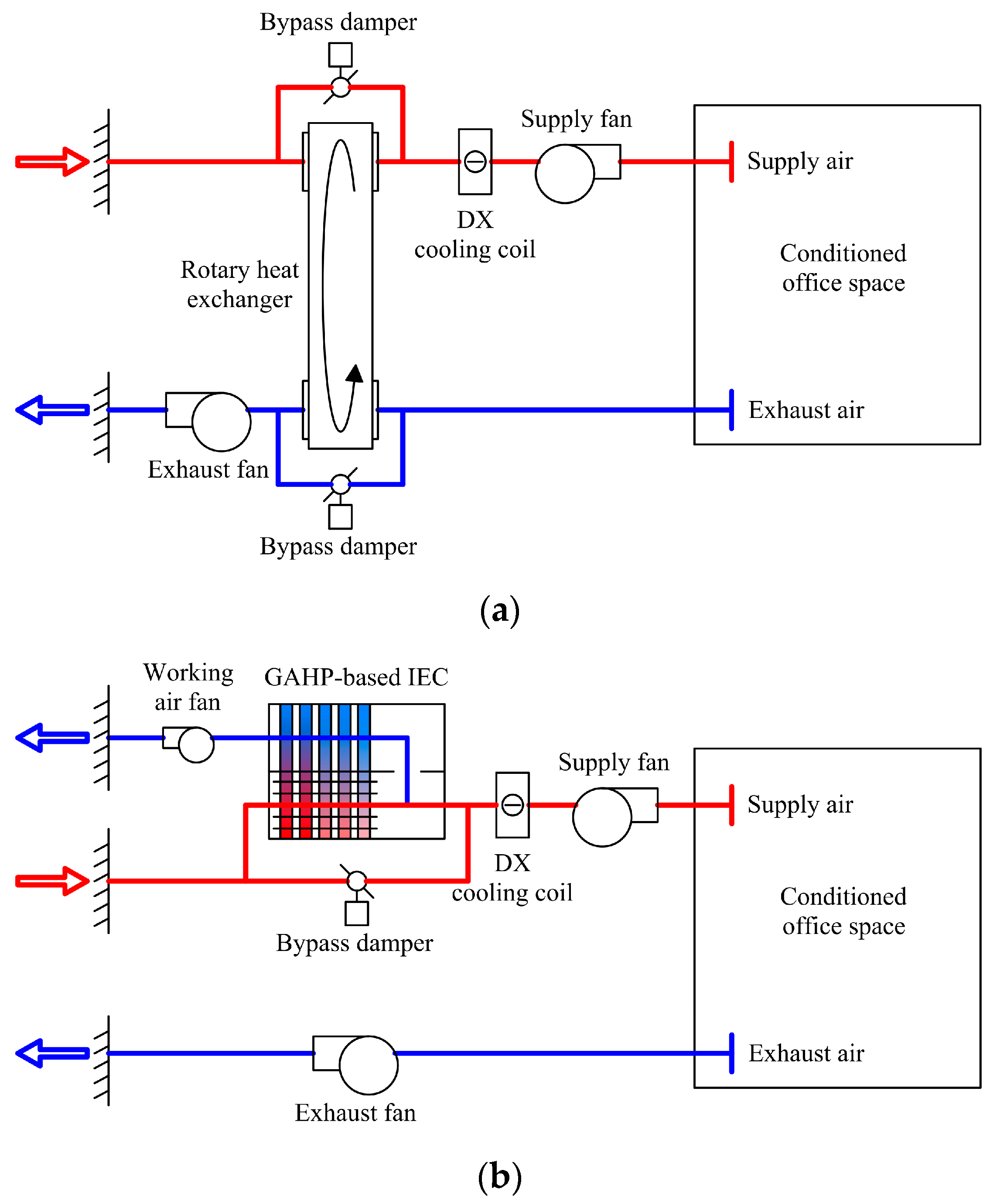
Putting all the mentioned issues together, here, the potential of utilizing GAHP to enhance the performance of a stand-alone DX cooling coil, which is employed to meet the thermal comfort for an office building, is examined. The proposed hybrid air conditioning system is investigated from different aspects, including technical, energy, and efficiency perspectives. Moreover, the results are compared with the integration of a RHE for heat recovery with a DX cooling coil, as a routine way to improve the performance of the DX cooling coil. The investigation was performed for the climatic condition of Poland, and knowing that DX cooling coils are one of the most common methods for building cooling in Europe, the result will help to achieve a reliable and practical method to implement a hybrid air conditioning system which has a better condition from technical, energy efficiency, economic, and techno-economic perspectives. It can contribute to diminishing the peak electricity demand as well.
2. Working Principle of a GAHP-Based IEC
A heat pipe where the working fluid cycle happens inside it due to gravity is known as a gravity-assisted heat pipe [33,34,
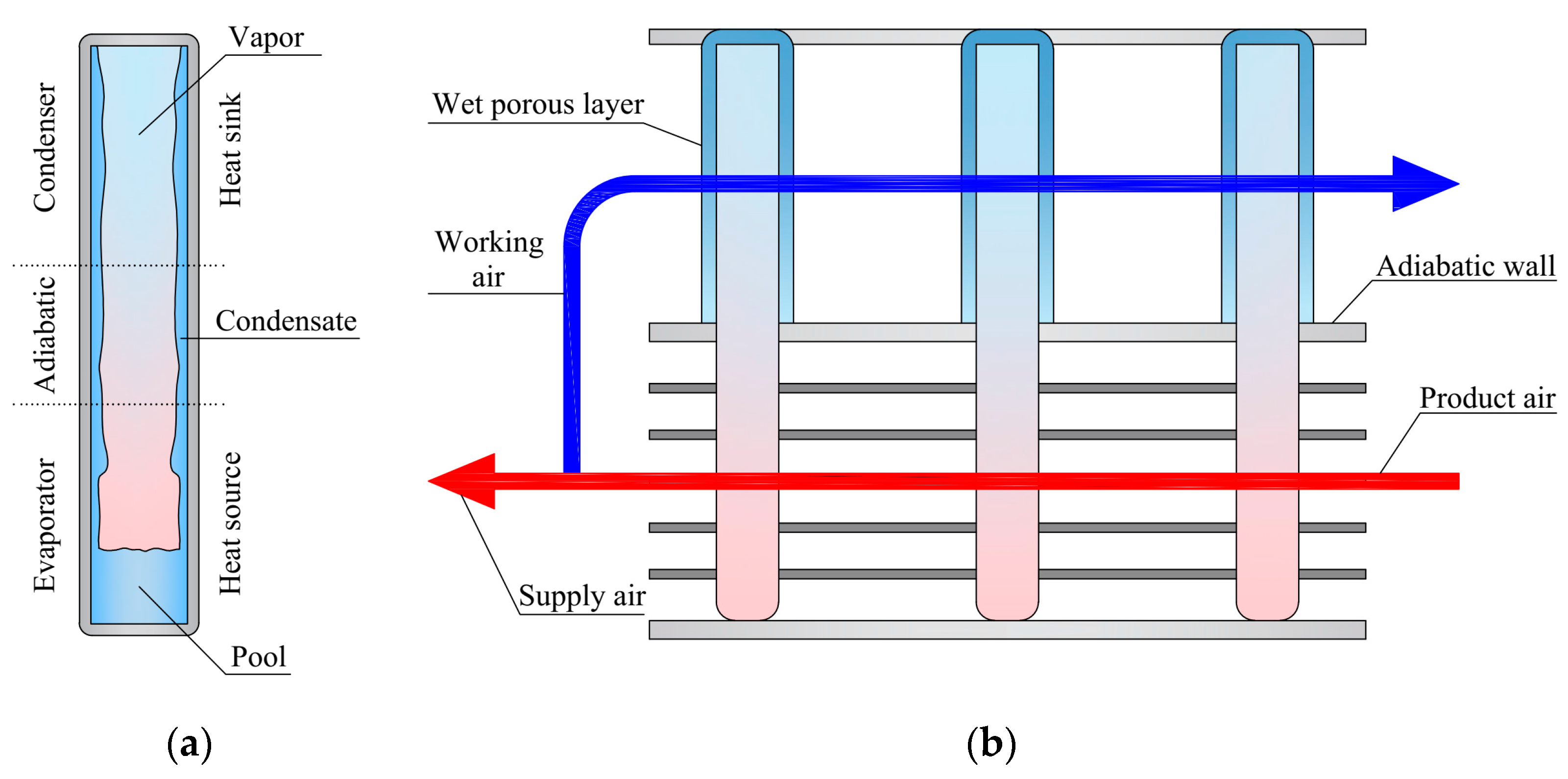
35]. This special kind of heat pipe is also called a two-phase closed thermosiphon or a wickless heat pipe. The schematic of a GAHP is depicted in Figure 1a. Based on the mentioned point, it can be concluded that the condenser of a GAHP always has to be placed above the evaporator to flow the fluid from the condenser to the evaporator based on the gravity. Generally, a GAHP consists of three characteristic regions, including the evaporator, adiabatic section, and condenser. The working principle is based on the phase change of the working fluid. After supplying heat flux through the evaporator wall to the working fluid, the working fluid starts to boil and to evaporate. As a result, the working fluid vapor moves to the condenser, where it condenses and releases the absorbed heat. Finally, the condensate returns to the pool inside the evaporator section to complete the GAHP thermal cycle.
Figure 1.
Visualization of an indirect evaporative cooler (IEC): (a) gravity-assisted heat pipe (GAHP); (b) airflow arrangement.
The regenerative-counter flow arrangement in the proposed IEC is established as shown in Figure 1b. In order to achieve better cooling performance, part of the outlet product airflow is branched to the wet channel and flows in countercurrent arrangement to the dry channel. The working fluid (moist air) absorbs sensible heat from the product airflow. The collected heat is then dissipated due to the water evaporation on the condenser’s outer surface. As a result, the supply airflow is cooled without changing the moisture content.
The wet section should be made of specially designed materials with high water retention and wettability (e.g., porous ceramic, porous plastic), which provides an even water distribution around the condensation part of the GAHP. Deionized water is used as the working fluid inside of a GAHP. Continuous plain fins for enhancement heat transfer are implemented only in the dry section of an IEC. The finned condensation section would result in difficulties with the water distribution on the outer surface of a GAHP.
3. Materials and Methods
3.1. Description of the Analyzed Systems
As mentioned before, two hybrid air conditioning systems are considered and compared together. It should be emphasized that the proposed HVAC systems run at the constant airflow volume (CAV) and are designed to supply 100% fresh air to conditioned office space. As a consequence, the supply air temperature is varied to meet the cooling loads. Figure 2 presents the schematic of the analyzed systems. The first design (System 1 in Figure 2a) is a conventional HVAC system consisting of the rotary heat exchanger and DX cooling coil. The efficiency of heat recovery was assumed 80% [36]. In the second design (System 2 in Figure 2b), a GAHP-based IEC is combined with a DX cooling coil, and air enters it and then goes to the cooling coil. In other words, in System 2 the inlet air is sensibly cooled by the IEC, and then DX cooling coil is employed to cover rest of the cooling load. It should be noted that in both investigated systems, the DX cooling coil dehumidifies the supply air.
Figure 2.
The schematic of the investigated hybrid air conditioning systems: (a) System 1 (rotary heat exchanger and DX cooling coil); (b) System 2 (GAHP-based IEC and DX cooling coil).
The main design parameters of GAHP-based IEC are listed in Table 2. In the authors’ previous study [32], the most favorable ranges of operating conditions for the GAHP-based IEC were established. On this basis, the geometrical parameters were set in order to ensure the required supply airflow rate to the conditioned space.
Table 2.
Main design parameters of the GAHP-based IEC.
3.2. Considered Case Study and Assumptions
A small office in Wroclaw, Poland, was adopted as a benchmark in the comparison of hybrid air conditioning systems. The main objective of the conducted analysis is to provide a comparison in the hot period. Considering this point, and in order to meet the required thermal comfort conditions, it is crucial to calculate cooling load accurately. The inputs for the cooling load calculation are reported in Table 3. These include structural information (area, U-value) and internal heat gains (occupancy, electric equipment, lighting).
Table 3.
The characteristics of the office room which is considered as the case study.
For this purpose, the cooling load calculation methodology based on the VDI 2078 standard (applicable method in Poland) is applied [37,38]. The parameters of ambient air are assumed in reference to the climatic curve for Wroclaw, Poland (with the maximum outside conditions equal to 30 °C and 45%RH) [37]. Figure 3 shows the climatic curve and the data of a typical meteorological year for Wroclaw [39]. The calculations are performed for cooling design-days during the assumed hot period, namely 23 July, 24 August, 22 September.
Figure 3.
Outdoor air conditions for Wroclaw during operating hours of the analyzed room.
Considering thermal comfort requirements, office room temperature is determined by the following control strategy [37]:
The cooling setpoint temperatures vary with the current outdoor air temperature They are the average temperature values estimated on the basis of the room temperature for the heating season and current outdoor air temperature.
Based on maximum cooling load estimation , the required supply airflow rate for providing indoor comfort conditions is calculated. This can be expressed by Equation (2). The temperature difference takes into account the difference between the supply and exhaust airflow temperature and is assumed to be equal to 6 °C. In the considered case study, the mixing ventilation is assumed. As a result, the exhaust airflow temperature is equal to the temperature in the human occupation zone.
3.3. Modeling the Performance of GAHP-Based IEC
In order to find the temperature and the humidity ratio throughout the GAHP-based IEC, a mathematical model is established on the basis of principles of heat and mass conservation. Schematic views of the computational element considered for numerical analysis and the thermal resistance network are shown in Figure 4. In the simplified approach, each row of GAHPs (described as superscript (i)) is considered as a separate computational element.
Figure 4.
Schematic view: (a) computational element for mathematical modeling; (b) thermal resistance network for GAHP.
The assumptions made to simplify the mathematical model are listed in Table 4. Using the given assumptions, the system of Equations (3)–(8) is derived, as shown in Table 5. The calculation program was written in MATLAB environment. The iterative method is adopted to meet the initial and boundary conditions (inlet and outlet parameters of product/working air).
Table 4.
Assumptions made to simplify the mathematical model.
Table 5.
Mathematical model equations for GAHP-based IEC.
From the thermal resistance network, as shown in Figure 4b, the overall heat transfer coefficient between the product airflow and the wet porous layer can be expressed by Equation (9). The thermal resistances R1–R6 denote the interface between the product air and the finned GAHP wall, the evaporator radial conduction, the evaporation of the working fluid, the condensation of the working fluid, the condenser radial conduction, and the wet porous layer conduction, respectively. Details of the calculation formulas can be found in [32].
The convective heat transfer coefficient in the finned dry section of the cooler is calculated based on Colburn j factor [46]:
The convective heat transfer coefficient in the wet section is determined based on correlation for Nusselt number for the staggered arrangement of tube banks [47]:
The analogy between heat transfer and mass transfer is adopted according to the Lewis relation, and to simplify the model, it is assumed to be 1. Therefore, the convective mass transfer coefficient can be expressed by Equation (12):
3.4. Validation of the Mathematical Model
The experimental data derived from Amer [30,48] were employed to validate the established model. The calculations were conducted by setting the same operating conditions as given in the experiments. The comparison between the simulation results and experimental data is presented in Figure 5. Two kinds of experimental cases with different ranges of inlet air temperature and relative humidity are presented. It was found that both the cooling capacity and wet-bulb effectiveness were predicted with a maximum discrepancy of about 5%, which confirms the accuracy of the developed model. However, it was observed that the obtained results were overestimated due to the assumptions of the mathematical model.
Figure 5.
Comparison between simulation results and experimental data (impact of inlet air temperature on cooling capacity and wet-bulb effectiveness).
3.5. Performance Evaluation
The energy effectiveness of the investigated hybrid air conditioning systems is described using the coefficient of performance (COP). COP is defined as the ratio of cooling capacity and electricity consumption:
As is mentioned in Table 2, the electricity consumption of GAHP-based IEC is assumed to be 150 W. It includes the power demand caused by the pressure drop [32] and the pump in the water distribution system. Electricity consumption by the DX cooling coil is referenced to the assumed of 3.5. Moreover, the electricity consumption of the RHE is assessed at 100 W.
The cooling capacity of DX cooling coil can be defined by Equation (14). It should be emphasized that the enthalpy difference is considered for the DX cooling coil owing to the dehumidification of supply air for both systems.
The cooling capacity of RHE and GAHP-based IEC can be referred to as the air temperature differences as the air is cooled at the constant moisture content (only sensible heat is transferred). These cooling capacities can be written as:
Air temperature differences in Equations (15) and (16) vary throughout the day as a function of the outdoor air temperature and the required supply air temperature (Figure 6).
Figure 6.
The key temperature values for the cooling design-day: (a) 24 August; (b) 22 September.
4. Results and Discussion
4.1. The Cooling Load
As mentioned, the cooling loads are estimated based on the VDI 2078 standard. In order to establish the worst cooling conditions for the HVAC systems, calculations are performed for three cooling design-days. The dates 23 July and 24 August were chosen due that they have the highest outdoor air temperatures, i.e., 30 °C. Moreover, 22 September is also included due to the southern location of the window. It should be noted that the lower position of the sun in the interim season results in a higher cooling load due to irradiation. Consequently, September is examined as a design month for south facade-dominated spaces.
In Figure 6, the key temperature values for the cooling design-day are presented. Due to the nearly identical outdoor air temperatures during design-days for July and August, 23 July is deliberately omitted in Figure 6. Moreover, 24 August corresponds to higher cooling loads. After the rearrangement of Equation (2), assuming the CAV system, it is also possible to plot the supply air temperature. Furthermore, the required temperature values in a conditioned office room to ensure thermal comfort are provided according to Equation (1).
As per Figure 6b, the temperature difference between the supply air and room temperature is equal to 6 °C in the case of overall peak cooling load (12:00 on 22 September in Figure 7). It should be noted that this is an acceptable temperature difference for the mixing ventilation.
Figure 7.
Hourly cooling loads for the selected design-days.
Figure 7 illustrates the hourly cooling load profiles of the considered office room. As indicated, the south facade determines the highest cooling load on 22 September, despite the lower outdoor air temperature. The peak cooling load which needs to be removed from the conditioned space is obtained on 22 September at 12:00, and it is equal to 2.63 kW.
The required supply airflow, mentioned in Table 6, is evaluated for the peak cooling load according to Equation (2), and it maintains a constant value of 1345 m3/h for both systems.
Table 6.
Determination of the supply airflow.
The conducted assessment indicates the maximum required cooling capacity for each system, as shown in Figure 8. As a result, it brings crucial data in terms of cooling system sizing. It is observed that the peak values of cooling capacity for System 1 and System 2 are 6.0 kW and 5.6 kW, respectively. In view of the foregoing considerations, the further analysis focuses on the cooling design-day with the maximum required cooling capacities, i.e., 24 August.
Figure 8.
Maximum required cooling capacities for System 1 and System 2 during the cooling season.
4.2. The Required Cooling Capacity Profiles
In Figure 9, the required cooling capacities are depicted for System 1. The needed cooling capacity of the DX cooling coil is obtained on the basis of the required supply air temperature and the constant supply airflow, and it is lower than using the DX cooling coil individually due to the RHE application.
Figure 9.
The cooling capacity of System 1: (a) the values; (b) the share covered by each component.
The peak cooling energy is 6.0 kWh, which occurs at 13:00. This is accompanied by a peak condition of the DX cooling coil of 4.3 kWh (Figure 9a). It is worth mentioning that the rotary heat exchanger provided the possibility of covering 27.7% of this cooling energy demand by recovering energy from exhaust air (Figure 9b). The rest of the cooling capacity, equal to 72.3%, is removed using the conventional vapor compression system. On the other hand, for the whole cooling design-day, System 1 delivers 53.5 kWh of cooling energy to the air-conditioned space. This sum includes 38.1 kWh from the DX cooling coil and 15.5 kWh from the RHE. The corresponding values for the share of each component in System 1 are approximately 71.1% and 28.9%, respectively.
It should be mentioned that the highest rate of heat recovery has a direct relationship with the temperature difference of exhaust air and outdoor air. This is due to the fact that as the outdoor air temperature increases, the temperature difference between the airflows in the rotary heat exchanger also increases. As a result, the maximum cooling energy recovered by the RHE of 1.8 kWh (Figure 9a) is obtained at 15:00, with the highest outdoor air temperature of 30 °C (Figure 6a).
In Figure 10, the hourly changes in the cooling capacity of System 2 during the design-day are presented. As observed, implementation of GAHP-based IEC is accompanied by a significant reduction of the required DX cooling coil capacity compared to System 1. Application of the novel GAHP-based IEC also results in a decrease in the overall cooling capacity in comparison with System 1 (from 53.5 kWh to 49.0 kWh per design-day). This results from the fact that System 1 utilizes more energy to dehumidify the supply air, due to the fact that the surface temperature of the DX cooling coil is below the dew-point temperature of supply airflow, and it causes the supply airflow to lose a part of its humidity content there. In the case of System 2, less dry supply airflow still meets the thermal comfort criteria in the conditioned office space, while relative humidity is kept below 60%, considering the moisture gains from people.
Figure 10.
The cooling capacity of System 2: (a) the values; (b) the share covered by each component.
The peak cooling energy is 5.6 kWh, which occurs at 13:00. System 2 delivers 2.4 kWh from the DX cooling coil and 3.2 kWh from the GAHP-based IEC of cooling energy to the office room (Figure 10a). It should be mentioned that the GAHP-based IEC provided the possibility of covering 57.2% of this cooling energy demand (Figure 10b). In other words, by the use of an environmentally friendly considered indirect evaporative cooler, i.e., GAHP-based IEC, the peak of cooling energy is reduced and requires 42.8% of that peak from the DX cooling coil. The maximum cooling energy supplied by the GAHP-based IEC of 3.3 kWh (Figure 10a) is achieved at 15:00, accompanied by the highest outdoor air temperature of 30 °C (Figure 6a).
In addition to this, for the whole cooling design-day, System 2 supplies 49.0 kWh of cooling energy to the air-conditioned office room. This sum contains 16.8 kWh from the DX cooling coil and 15.5 kWh from the GAHP-based IEC. The corresponding values for the share of each component in System 2 are approximately 34.3% and 65.7%, respectively. Compared to System 1, a significant reduction in the use of conventional vapor compression cooling can be observed from 38.1 kWh to 16.8 kWh (55.1% reduction).
4.3. Electricity Consumption, COP, and Operating Cost
Figure 11 shows the comparison of System 1 and System 2 from electricity consumption and COP points of view.
Figure 11.
The electricity consumption and COP profiles on the cooling design-day: (a) System 1; (b) System 2.
The electricity consumption of System 2 is significantly lower than System 1, as shown in Figure 11a. By implementation of the novel GAHP-based IEC, a reduction in total electricity consumption is achieved in comparison with System 1 (from 12.34 kWh to 6.79 kWh per design-day). The proposed system requires 55.0% of original electricity consumption. As a result, diminishing a major part of the electricity demand in the peak condition, which comes from using the DX cooling coil, is another advantage of employing the proposed GAHP-based IEC hybrid air conditioning system. A peak in electricity consumption during the analyzed cooling design-day corresponds with the occurrence of maximum cooling energy, which is observed at 13:00. Furthermore, this estimated consumption of electricity for both systems is approximately 1.37 kWh and 0.87 kWh, respectively.
As per Figure 11b, based on the obtained profiles, the average value of COP for System 1 is equal to 4.34. This is a higher value than the mentioned COP for a stand-alone DX cooling coil. It comes from the application of sensible heat recovery by a rotary heat exchanger. In addition, the average value of COP for System 2 is equal to 7.14 with a peak of 9.47 at 17:00, which is considerably higher than System 1. This means that the implementation of GAHP-based IEC improves the cooling performance by 39.2% compared to System 1. It should be noted that the COP value at 18:00 is excluded from the calculation of average COP for System 2 to better reflect the real conditions. At this point, the whole cooling energy is supplied by the GAHP-based IEC at minimum electricity input.
Due to the novelty of the proposed GAHP-based IEC, the investment cost is difficult to estimate. Obviously, the cost of a prototype device will exceed the potential savings and will affect the financial profitability assessment. For that reason, Table 7 shows the monthly operating costs for each system. The number of cooling hours is estimated on the basis of meteorological data from [39]. In order to estimate the electricity and water consumption, the calculation of cooling loads in the function of outdoor air temperature was conducted. Due to the cooling loads in the analyzed conditioned space, the outdoor temperature of 21 °C was set as a turn-on point for cooling devices. For lower temperatures during the cooling season, only the supply fan was operated to deliver the fresh air. The obtained electricity and water consumption were applied to assess operating costs on the basis of electricity and water prices for Poland. The implementation of System 2 benefits in the reduction of total operating costs by 51.7%. The total operating cost discrepancy between System 1 and System 2 is PLN 214.45.
Table 7.
Monthly operating costs for each system.
5. Conclusions
In the present work, a novel hybrid air conditioning system in which gravity-assisted heat-pipe-based indirect evaporative cooling was used in combination with a direct expansion cooling coil was proposed and investigated. The possibility of enhancing energy efficiency in the system to bring the thermal comfort zone in an air-conditioned office space in Poland was discussed and compared with the rotary heat exchanger and DX cooling coil combination as the conventional hybrid system. A mathematical model to describe the novel air cooler was also developed. The results showed that, on the cooling design-day, the proposed system is able to perform better in terms of reducing electricity consumption and increasing the coefficient of performance compared to the conventional one.
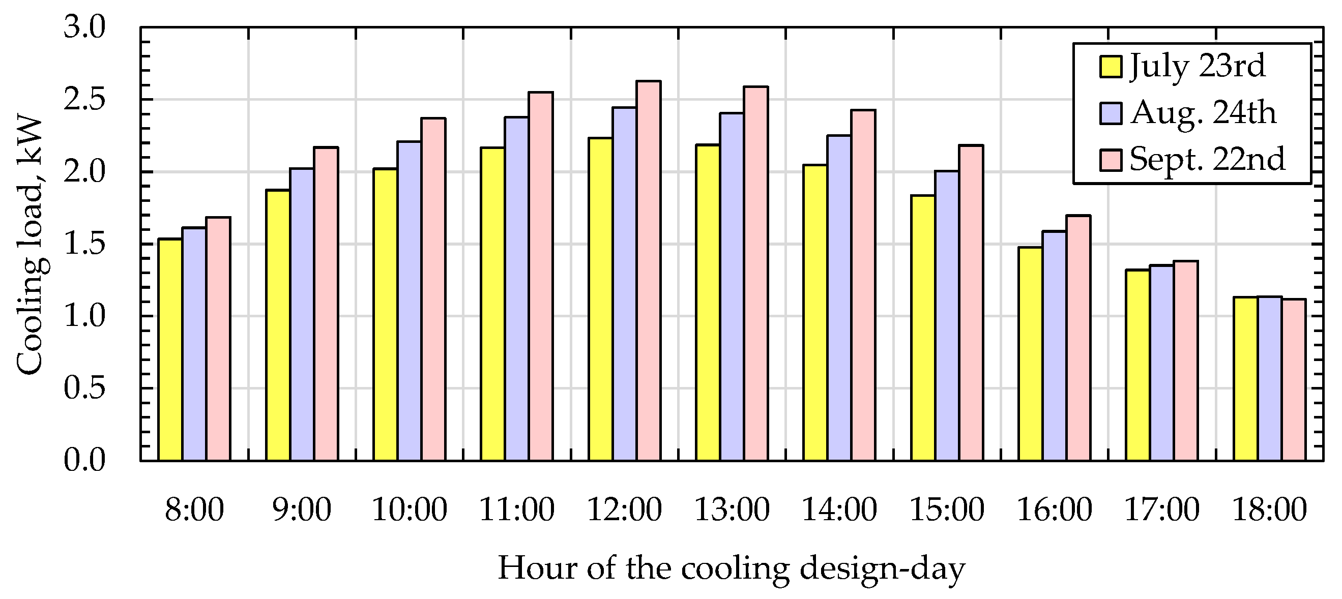
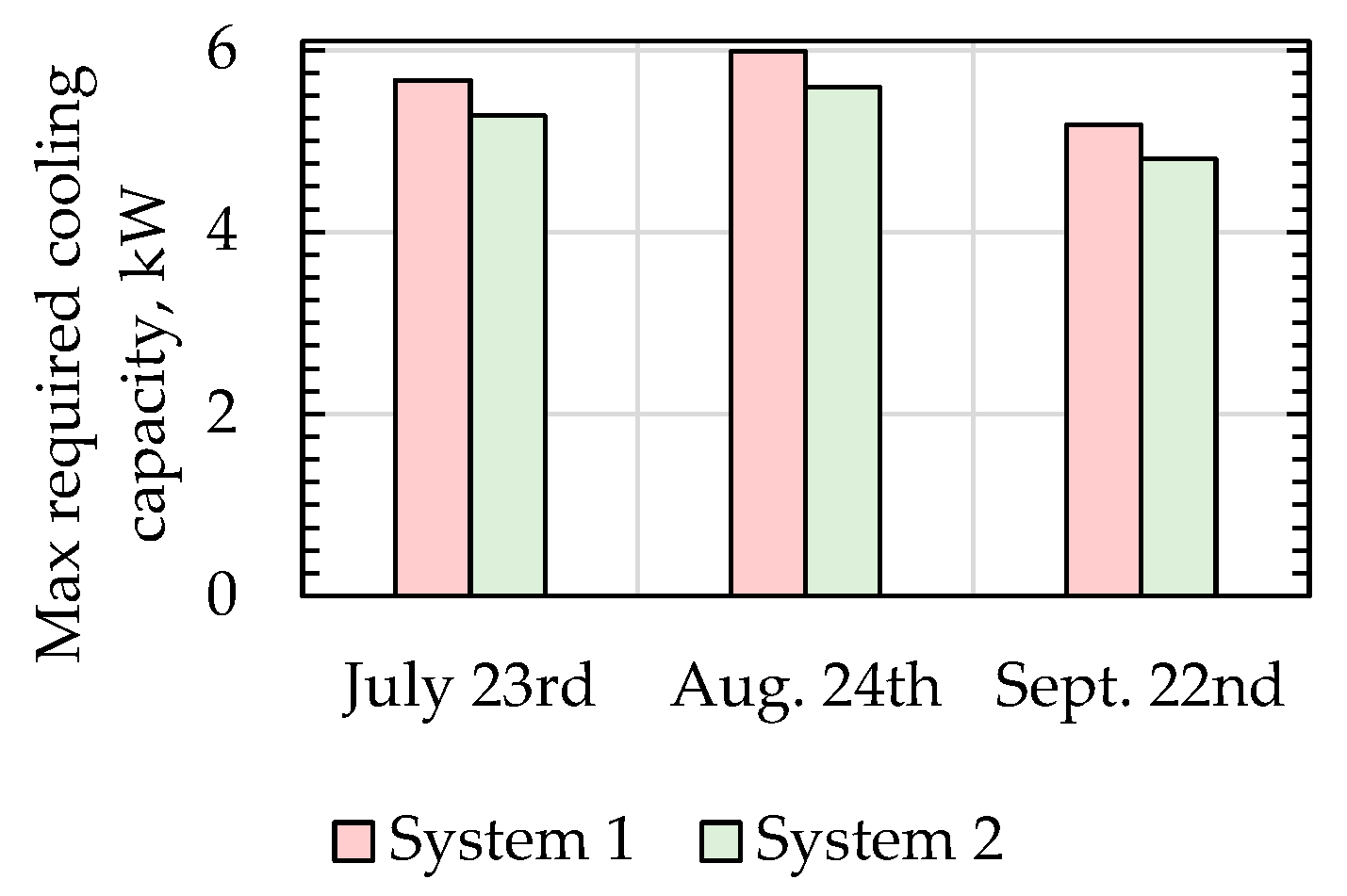
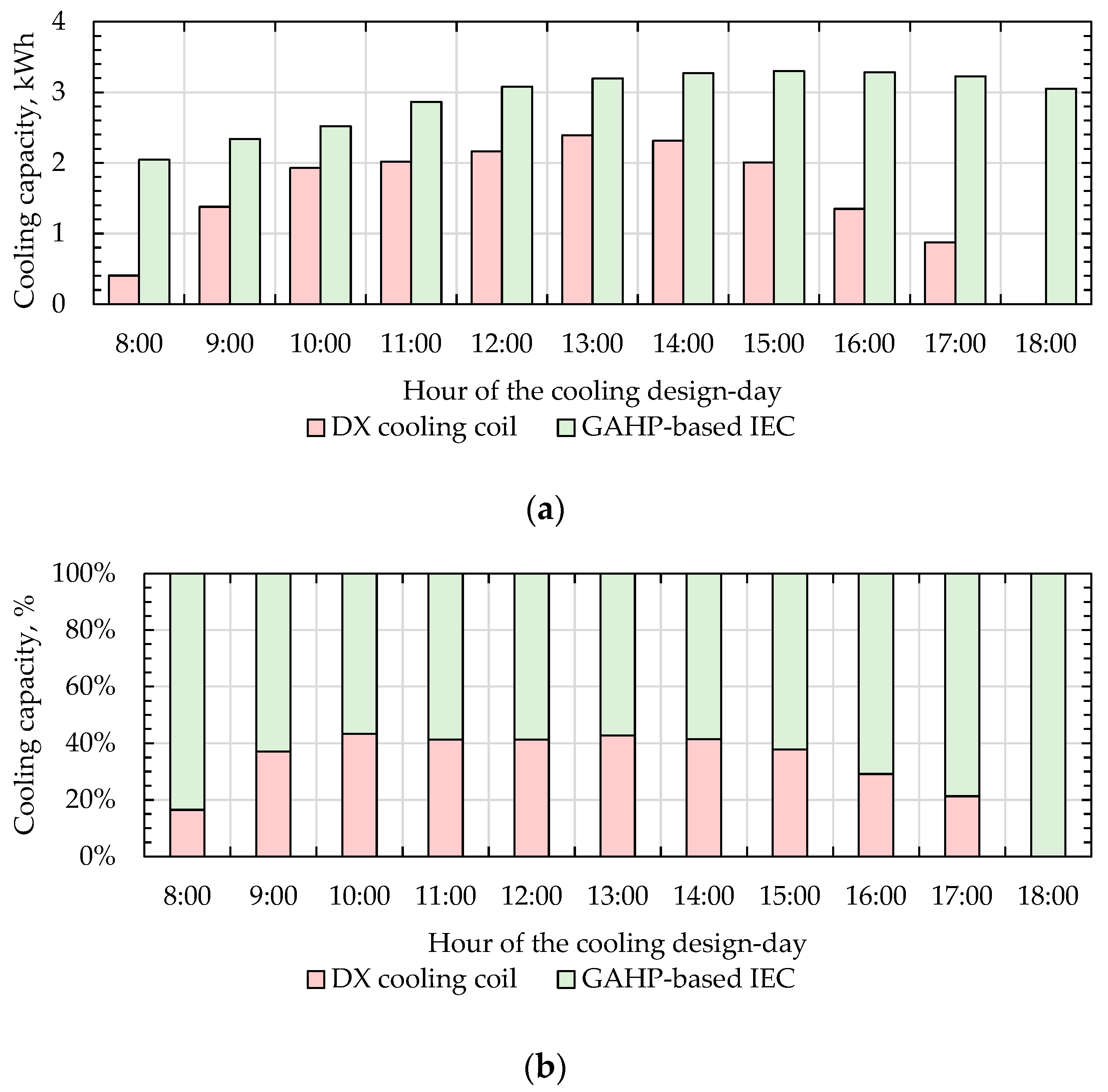
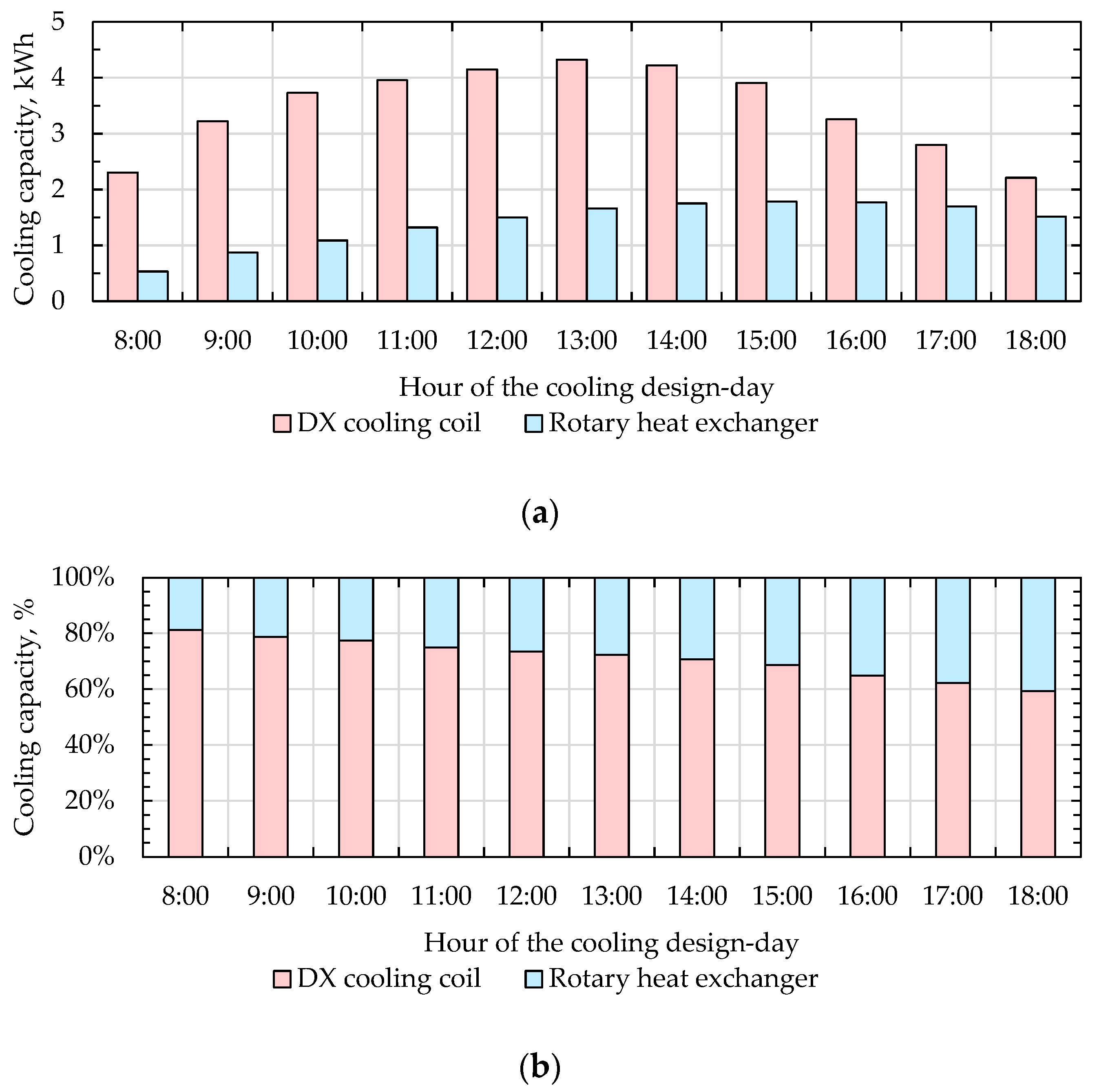
The following findings according to the design-day of August 24 can be listed from this investigation. It was found that for the considered case study, the peak values of cooling capacity for System 1 and System 2 are 6.0 kW and 5.6 kW, respectively. For the design-day, System 1 delivers 53.5 kWh of cooling energy to the air-conditioned space, 28.9% of which was covered by the heat recovery system. On the other hand, System 2 supplies 49.0 kWh of cooling energy to the air-conditioned space, 65.7% of which was covered by the indirect evaporative cooler.
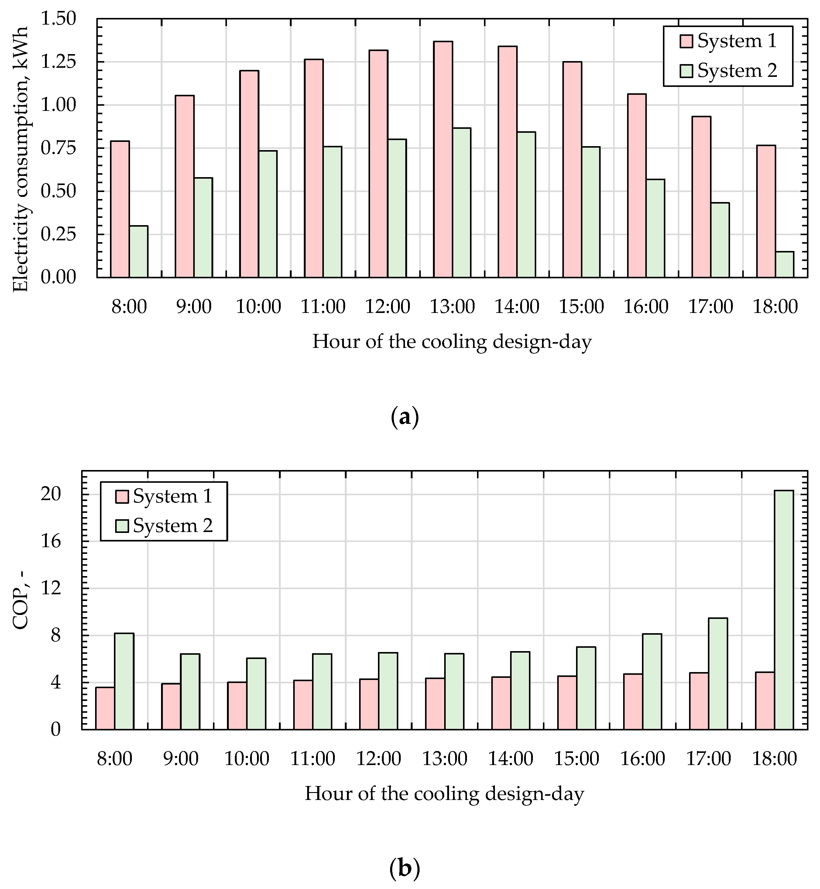
In addition, a significant reduction of 55.1% in the use of the DX cooling coil can be observed in terms of System 2. Hence, 55.0% of original electricity consumption was required by the proposed System 2. The proposed hybrid HVAC system improved the COP by 39.2% compared to System 1. Moreover, total operating cost was reduced by 51.7%.
Author Contributions
Conceptualization, K.R.; methodology, K.R. and A.S.; software, K.R.; formal analysis, K.R.; investigation, K.R. and S.J.; data curation, K.R.; writing—original draft preparation, K.R. and A.S.; writing—review and editing, K.R., A.S., J.D. and M.A.S.; visualization, K.R.; supervision, K.R. All authors have read and agreed to the published version of the manuscript.
Funding
This research received no external funding.
Institutional Review Board Statement
Not applicable.
Informed Consent Statement
Not applicable.
Data Availability Statement
Data are contained within the article.
Conflicts of Interest
The authors declare no conflict of interest.
Nomenclature
| A | surface area, m2 |
| COP | coefficient of performance |
| cp | specific heat capacity, J/kgK |
| do | GAHP outer diameter, m |
| DX | direct expansion cooling coil |
| GAHP | gravity-assisted heat pipe |
| convective heat transfer coefficient, W/m2K | |
| H | specific enthalpy of moist air, J/kg |
| evaporation heat of water at reference temperature (0 °C), J/kg | |
| convective mass transfer coefficient, kg/m2s | |
| IEC | indirect evaporative cooling, indirect evaporative cooler |
| j | Colburn factor |
| Le | Lewis factor, defined as |
| mass flow rate, kg/s | |
| Nu | Nusselt number |
| P | pressure, Pa |
| Pr | Prandtl number |
| Q | cooling capacity, cooling load, W |
| R | thermal resistance, K/W |
| RH | relative humidity, % |
| RHE | rotary heat exchanger |
| Redo | Reynolds number based on do |
| s | spacing between adjacent fins, m |
| SL | tube spacing in airflow direction, m |
| ST | tube spacing normal to flow, m |
| t | temperature, °C |
| average bulk temperature, °C | |
| U | overall heat transfer coefficient, W/m2K |
| W | required power, W |
| V | airflow rate, m3/s |
| Greek Letters | |
| ε | effectiveness |
| ρ | density, kg/m3 |
| ω | humidity ratio, kg/kg |
| average bulk humidity ratio, kg/kg | |
| Subscripts | |
| atm | atmospheric |
| c.load | cooling load |
| cs | cooling setpoint |
| hs | heating season |
| i | order of the computational element |
| oa | outdoor air |
| p | product air |
| sa | supply airflow |
| w | working air |
| WB | wet-bulb temperature |
| wf | water film and working air interface |
References
- Saedpanah, E.; Pasdarshahri, H. Performance Assessment of Hybrid Desiccant Air Conditioning Systems: A Dynamic Approach Towards Achieving Optimum 3E Solution Across the Lifespan. Energy 2021, 234, 121151. [Google Scholar] [CrossRef]
- Chen, E.; Chen, J.; Jia, T.; Zhao, Y.; Dai, Y. A Solar-Assisted Hybrid Air-Cooled Adiabatic Absorption and Vapor Compression Air Conditioning System. Energy Convers. Manag. 2021, 250, 114926. [Google Scholar] [CrossRef]
- Jani, D.B.; Mishra, M.; Sahoo, P.K. Experimental Investigation on Solid Desiccant-Vapor Compression Hybrid Air-Conditioning System in Hot and Humid Weather. Appl. Therm. Eng. 2016, 104, 556–564. [Google Scholar] [CrossRef]
- Kumar, S.; Salins, S.S.; Reddy, S.V.K.; Nair, P.S. Comparative Performance Analysis of a Static & Dynamic Evaporative Cooling Pads for Varied Climatic Conditions. Energy 2021, 233, 121136. [Google Scholar] [CrossRef]
- Englart, S.; Rajski, K. Performance Investigation of a Hollow Fiber Membrane-Based Desiccant Liquid Air Dehumidification System. Energies 2021, 14, 3320. [Google Scholar] [CrossRef]
- Salins, S.S.; Reddy, S.K.; Kumar, S. Effect of Climatic Conditions on the Performance of a Multistage Dynamic Dehumidifier Test Rig. Build. Environ. 2021, 205, 108245. [Google Scholar] [CrossRef]
- Peci, F.; Comino, F.; Ruiz de Adana, M. Performance of an Unglazed Transpire Collector in the Facade of a Building for Heating and Cooling in Combination with a Desiccant Evaporative Cooler. Renew. Energy 2018, 122, 460–471. [Google Scholar] [CrossRef]
- Sohani, A.; Sayyaadi, H.; Hoseinpoori, S. Modeling and Multi-Objective Optimization of an M-Cycle Cross-Flow Indirect Evaporative Cooler Using the GMDH Type Neural Network. Int. J. Refrig. 2016, 69, 186–204. [Google Scholar] [CrossRef]
- Sohani, A.; Sayyaadi, H.; Mohammadhosseini, N. Comparative Study of the Conventional Types of Heat and Mass Exchangers to Achieve the Best Design of Dew Point Evaporative Coolers at Diverse Climatic Conditions. Energy Convers. Manag. 2018, 158, 327–345. [Google Scholar] [CrossRef]
- Kowalski, P.; Kwiecień, D. Evaluation of Simple Evaporative Cooling Systems in an Industrial Building in Poland. J. Build. Eng. 2020, 32, 101555. [Google Scholar] [CrossRef]
- Sayegh, M.A.; Hammad, M.; Faraa, Z. Comparison of Two Methods of Improving Dehumidification in Air Conditioning Systems: Hybrid System (Refrigeration Cycle–Rotary Desiccant) and Heat Exchanger Cycle. Energy Procedia 2011, 6, 759–768. [Google Scholar] [CrossRef] [Green Version]
- Sohani, A.; Sayyaadi, H.; Hasani Balyani, H.; Hoseinpoori, S. A Novel Approach Using Predictive Models for Performance Analysis of Desiccant Enhanced Evaporative Cooling Systems. Appl. Therm. Eng. 2016, 107, 227–252. [Google Scholar] [CrossRef]
- Sohani, A.; Sayyaadi, H. Design and Retrofit Optimization of the Cellulose Evaporative Cooling Pad Systems at Diverse Climatic Conditions. Appl. Therm. Eng. 2017, 123, 1396–1418. [Google Scholar] [CrossRef]
- Chauhan, S.S.; Rajput, S.P.S. Experimental Analysis of an Evaporative–Vapour Compression Based Combined Air Conditioning System for Required Comfort Conditions. Appl. Therm. Eng. 2017, 115, 326–336. [Google Scholar] [CrossRef]
- Ndukaife, T.A.; Nnanna, A.G.A. Optimization of Water Consumption in Hybrid Evaporative Cooling Air Conditioning Systems for Data Center Cooling Applications. Heat Transf. Eng. 2019, 40, 559–573. [Google Scholar] [CrossRef]
- Fong, K.F.; Lee, C.K.; Lin, Z. Investigation on Effect of Indoor Air Distribution Strategy on Solar Air-Conditioning Systems. Renew. Energy 2019, 131, 413–421. [Google Scholar] [CrossRef]
- Cui, X.; Islam, M.R.; Chua, K.J. An Experimental and Analytical Study of a Hybrid Air-Conditioning System in Buildings Residing in Tropics. Energy Build. 2019, 201, 216–226. [Google Scholar] [CrossRef]
- Ahmed, M.S.; Elsaid, A.M. Effect of Hybrid and Single Nanofluids on the Performance Characteristics of Chilled Water Air Conditioning System. Appl. Therm. Eng. 2019, 163, 114398. [Google Scholar] [CrossRef]
- Zanchini, E.; Naldi, C. Energy Saving Obtainable by Applying a Commercially Available M-Cycle Evaporative Cooling System to the Air Conditioning of an Office Building in North Italy. Energy 2019, 179, 975–988. [Google Scholar] [CrossRef]
- Guan, B.; Liu, X.; Zhang, T.; Ma, Z.; Chen, L.; Chen, X. Experimental and Numerical Investigation of a Novel Hybrid Deep-Dehumidification System Using Liquid Desiccant. Energy Convers. Manag. 2019, 192, 396–411. [Google Scholar] [CrossRef]
- Zhang, L.; Zha, X.; Song, X.; Zhang, X. Optimization Analysis of a Hybrid Fresh Air Handling System Based on Evaporative Cooling and Condensation Dehumidification. Energy Convers. Manag. 2019, 180, 83–93. [Google Scholar] [CrossRef]
- Yang, Y.; Ren, C.; Wang, Z.; Luo, B. Theoretical Performance Analysis of a New Hybrid Air Conditioning System in Hot-Dry Climate. Int. J. Refrig. 2020, 116, 96–107. [Google Scholar] [CrossRef]
- Venkateswara Rao, V.; Datta, S.P. A Feasibility Assessment of Single to Multi/Hybrid Evaporative Coolers for Building Air-Conditioning across Diverse Climates in India. Appl. Therm. Eng. 2020, 168, 114813. [Google Scholar] [CrossRef]
- Duan, Z.; Zhao, X.; Liu, J.; Zhang, Q. Dynamic Simulation of a Hybrid Dew Point Evaporative Cooler and Vapour Compression Refrigerated System for a Building Using EnergyPlus. J. Build. Eng. 2019, 21, 287–301. [Google Scholar] [CrossRef]
- Fong, K.F.; Lee, C.K. Solar Desiccant Cooling System for Hot and Humid Region–A New Perspective and Investigation. Sol. Energy 2020, 195, 677–684. [Google Scholar] [CrossRef]
- Chen, Y.; Liu, Y.; Wang, D.; Luo, X.; Liu, J.; Liu, J.; Wang, Y.; Liu, J. Performance and Optimization of a Novel Solar-Driven Liquid Desiccant Air Conditioning System Suitable for Extremely Hot and Humid Climates. Energy Convers. Manag. 2020, 215, 112899. [Google Scholar] [CrossRef]
- Liu, W.; Kalbasi, R.; Afrand, M. Solutions for Enhancement of Energy and Exergy Efficiencies in Air Handling Units. J. Clean. Prod. 2020, 257, 120565. [Google Scholar] [CrossRef]
- Al Horr, Y.; Tashtoush, B.; Chilengwe, N.; Musthafa, M. Operational Mode Optimization of Indirect Evaporative Cooling in Hot Climates. Case Stud. Therm. Eng. 2020, 18, 100574. [Google Scholar] [CrossRef]
- Riffat, S.B.; Zhu, J. Mathematical Model of Indirect Evaporative Cooler Using Porous Ceramic and Heat Pipe. Appl. Therm. Eng. 2004, 24, 457–470. [Google Scholar] [CrossRef]
- Boukhanouf, R.; Amer, O.; Ibrahim, H.; Calautit, J. Design and Performance Analysis of a Regenerative Evaporative Cooler for Cooling of Buildings in Arid Climates. Build. Environ. 2018, 142, 1–10. [Google Scholar] [CrossRef]
- Alharbi, A.; Almaneea, A.; Boukhanouf, R. Integrated Hollow Porous Ceramic Cuboids-Finned Heat Pipes Evaporative Cooling System: Numerical Modelling and Experimental Validation. Energy Build. 2019, 196, 61–70. [Google Scholar] [CrossRef]
- Rajski, K.; Danielewicz, J.; Brychcy, E. Performance Evaluation of a Gravity-Assisted Heat Pipe-Based Indirect Evaporative Cooler. Energies 2020, 13, 200. [Google Scholar] [CrossRef] [Green Version]
- Danielewicz, J.; Sayegh, M.A.; Śniechowska, B.; Szulgowska-Zgrzywa, M.; Jouhara, H. Experimental and Analytical Performance Investigation of Air to Air Two Phase Closed Thermosyphon Based Heat Exchangers. Energy 2014, 77, 82–87. [Google Scholar] [CrossRef] [Green Version]
- Jafari, D.; Franco, A.; Filippeschi, S.; di Marco, P. Two-Phase Closed Thermosyphons: A Review of Studies and Solar Applications. Renew. Sustain. Energy Rev. 2016, 53, 575–593. [Google Scholar] [CrossRef]
- Guichet, V.; Jouhara, H. Condensation, Evaporation and Boiling of Falling Films in Wickless Heat Pipes (Two-Phase Closed Thermosyphons): A Critical Review of Correlations. Int. J. Thermofluids 2020, 1-2, 100001. [Google Scholar] [CrossRef]
- Hoval Rotary Heat Exchangers (For Energy Recovery in Ventilation Systems and in Process Engineering). In Design Handbook; Hoval Aktiengesellschaft: Vaduz, Liechtenstein, 2021; Available online: https://www.hoval-energyrecovery.com/zoolu-website/media/document/26503/Handbook_for_design%2C_installation_and_operation.PDF (accessed on 23 February 2022).
- Pelech, A. Fundamentals of Ventilation and Air Conditioning (in Polish), 4th ed.; Oficyna Wydawnicza Politechniki Wrocławskiej: Wroclaw, Poland, 2013; ISBN 978-83-7493-641-5. [Google Scholar]
- VDI 2078 Cooling Load Calculation of Air-Conditioned Rooms (VDI Cooling Load Regulations); Engl. VDI-Gesellschaft Bauen und Gebäudetechnik: Düsseldorf, Germany, 1996.
- Poland’s Open Data Portal, Typical Meteorological Year for Wrocław. Available online: https://dane.gov.pl/dataset/797,typowe-lata-meteorologiczne-i-statystyczne-dane-klimatyczne-dla-obszaru-polski-do-obliczen-energetycznych-budynkow (accessed on 23 February 2022).
- Heidarinejad, G.; Moshari, S. Novel Modeling of an Indirect Evaporative Cooling System with Cross-Flow Configuration. Energy Build. 2015, 92, 351–362. [Google Scholar] [CrossRef]
- Cui, X.; Chua, K.J.; Islam, M.R.; Yang, W.M. Fundamental Formulation of a Modified LMTD Method to Study Indirect Evaporative Heat Exchangers. Energy Convers. Manag. 2014, 88, 372–381. [Google Scholar] [CrossRef]
- Fakhrabadi, F.; Kowsary, F. Optimal Design of a Regenerative Heat and Mass Exchanger for Indirect Evaporative Cooling. Appl. Therm. Eng. 2016, 102, 1384–1394. [Google Scholar] [CrossRef]
- Ren, C.; Yang, H. An Analytical Model for the Heat and Mass Transfer Processes in Indirect Evaporative Cooling with Parallel/Counter Flow Configurations. Int. J. Heat Mass Transf. 2006, 49, 617–627. [Google Scholar] [CrossRef]
- Shabgard, H.; Allen, M.J.; Sharifi, N.; Benn, S.P.; Faghri, A.; Bergman, T.L. Heat Pipe Heat Exchangers and Heat Sinks: Opportunities, Challenges, Applications, Analysis, and State of the Art. Int. J. Heat Mass Transf. 2015, 89, 138–158. [Google Scholar] [CrossRef]
- Chen, Y.; Luo, Y.; Yang, H. A Simplified Analytical Model for Indirect Evaporative Cooling Considering Condensation from Fresh Air: Development and Application. Energy Build. 2015, 108, 387–400. [Google Scholar] [CrossRef]
- Kim, N.H.; Youn, B.; Webb, R.L. Air-Side Heat Transfer and Friction Correlations for Plain Fin-and-Tube Heat Exchangers with Staggered Tube Arrangements. J. Heat Transf. 1999, 121, 662–667. [Google Scholar] [CrossRef]
- Žukauskas, A.; Ulinskas, R. Efficiency Parameters for Heat Transfer in Tube Banks. Heat Transf. Eng. 1985, 6, 19–25. [Google Scholar] [CrossRef]
- Amer, O. A Heat Pipe and Porous Ceramic Based Sub Wet-Bulb Temperature Evaporative Cooler: A Theoretical and Experimental Study. Ph.D. Thesis, University of Nottingham, Nottingham, UK, 2017. [Google Scholar]
Publisher’s Note: MDPI stays neutral with regard to jurisdictional claims in published maps and institutional affiliations. |
© 2022 by the authors. Licensee MDPI, Basel, Switzerland. This article is an open access article distributed under the terms and conditions of the Creative Commons Attribution (CC BY) license (https://creativecommons.org/licenses/by/4.0/).