Article

A Generalized Predictive Controller for a Wind Turbine Providing Frequency Support for a Microgrid

by
Carlos E. Prieto Cerón
1,*,
Luís F. Normandia Lourenço
1,
Juan S. Solís-Chaves
2 and
Alfeu J. Sguarezi Filho
1
1
Center for Engineering, Modeling and Applied Social Sciences (CECS), Federal University of ABC (UFABC), Santo Andre 09210-580, Brazil
2
Mechatronic Enginering Department, ECCI University, Cl. 51 # 19-12, Bogotá 110231, Colombia
*
Author to whom correspondence should be addressed.
Energies 2022, 15(7), 2562; https://doi.org/10.3390/en15072562
Submission received: 1 March 2022 / Revised: 23 March 2022 / Accepted: 29 March 2022 / Published: 1 April 2022

Abstract

:
The power system is moving away from the centralized generation paradigm. One of the current trends is the microgrid concept, where loads, small generators and renewable energy resources (RERs) that are in close proximity are controlled as one entity. Microgrids also allow for an increase in power availability as they can continue to supply electric power to loads even in the absence of a connection to the main grid. During the transition to islanded operation, microgrids may be subject to frequency disturbances caused by the power imbalance between load and generation. When microgrids contain high shares of renewable energy, the challenge is significantly higher due to the control strategies that aim to maximize power production, which are typically applied to RERs and render them insensitive to grid changes. Therefore, new control strategies need to be developed to enable the participation of RERs in the support of the frequency response. This work proposes a predictive control strategy that is based on a generalized predictive controller (GPC) being applied to the grid side converter of a doubly fed induction generator (DFIG) wind turbine to enable frequency support capabilities. The control objective was to track a time varying power reference signal that was generated according to the deviation from the nominal frequency, thereby enabling the energy storage device to inject power into the microgrid without a communication system. The GPC is a controller belonging to the family of model predictive controllers (MPCs), the main principles of which are the use of a system model to predict future states and the choice of an optimal input to ensure that the reference values are followed. To validate the proposed control strategy, a microgrid was simulated in MATLAB Simscape Electrical. The frequency response using the proposed GPC strategy was compared to another MPC-based strategy, known as finite control set, and a scenario in which the DFIG was not equipped with frequency support capabilities. The results show that the proposed strategy was able to improve the frequency response of the microgrid, reduce frequency oscillations and increase the value of the frequency nadir.

Graphical Abstract

1. Introduction

The organization of power systems is changing to accommodate the growing penetration levels of renewable energy resources (RERs). The once vertical system in which large synchronous generators were responsible for power generation is turning into a distributed system in which small RERs interfaced by power electronics are generating power at the distribution level. The proximity between RERs and the loads in distribution networks facilitates the organization of power systems as microgrids [1,2,3,4].
Microgrids are an efficient way of integrating loads and generation at the distribution level, which benefits from smaller distances between generation and loads, improves the voltage profile and diminishes power losses [5]. These systems were also conceived as a way to improve the reliability of the power supply to its loads, thereby keeping the lights on even when the microgrid is disconnected from the bulk power system. The transitions to the islanded condition and the islanded operation of microgrids are very complex tasks to be carried out operationally, especially when RERs that are integrated by power converters are present.
When microgrids transition into islanded mode, there is a power imbalance that arises from the mismatch between the generated and consumed power within the microgrid. However, RERs, such as doubly fed induction generator (DFIG) wind turbines, are typically controlled to extract the maximum power available by following maximum power point tracking (MPPT) strategies. This operation strategy does not allow wind turbines to participate in the frequency support of microgrids as they do not respond to changes in frequency due to the MPPT strategies [6]. As a consequence, the responsibility of frequency support falls exclusively to smaller synchronous generators that are located in microgrids [7,8].
To enable a DFIG-based wind turbine to participate in the frequency response of microgrids, a modification to the MPPT strategy must be made. Two common approaches are deloading [9,10,11,12] and the use of the stored kinetic energy in the mechanical rotor [13,14,15,16,17,18,19,20]. The deloaded operation of a wind turbine consists of deliberately dislocating the operating point from the maximum power point (MPP) to enable a power reserve. There are a number of ways to use the kinetic energy stored in the mechanical rotor through the modification of the control strategy of the DFIG, which could be performed by a droop controller or a synthetic inertia controller, such as those employed in the fast frequency response [21]. However, these methods share three characteristics [8]:
1.
They are applied to the rotor side converter (RSC);
2.
They dislocate the operation from the MPP;
3.
They rely on fixed pulse width modulation (PWM) frequencies.
Hence, even when wind turbines are modified to have frequency support capabilities, the grid side converter (GSC) is in charge of the DC voltage control in the back-to-back (B2B) circuit capacitor at its rated level. In this work, we investigated a different modification, which allowed the GSC to be the converter that provided grid support capabilities. This was carried out by allocating a battery energy storage system (BESS) in parallel to the DC link capacitance of the B2B converter. Then, the GSC converter follows a power reference given by a frequency droop injecting/absorbing power stored in the BESS to provide frequency support [7,8].
To implement the controls of machine drives and storage systems, an alternative method that has attracted much research interest over the past three decades is the use of model-based predictive controllers (MBPC or, simply, MPC). The operating principles and constitutive elements of all MBPCs consist of a system model for predictions, a cost function and an optimization algorithm [22,23,24]. Although they require an optimization process, MPCs do not require high computational efforts compared to controllers that were developed using non-linear models and, additionally, they have a good capacity to deal with coupling between system variables [25].
Generalized predictive controllers (GPC) are included in the family of MBPCs and use a discretized version of the transfer function model of the plant. The theory behind GPCs was proposed in the late 1980s by [26]. Clarke and colleagues also proposed some applications and extensions for GPCs, as detailed in [27]. In the mid 1990s, a GPC application in the d q reference frame for the regulation of the steady-state stator currents of an induction machine was presented in [28]. In recent years, GPCs have found applications in DFIG-based wind energy conversion systems but have not been restricted to DFIG-based wind turbines, as seen in works such as [29,30,31]. In [32], a long-range GPC was applied to a wind turbine RSC under normal operating conditions. In [33], a robust GPC was applied to an RSC that aimed to mitigate the electromagnetic torque oscillations in the rotor of a DFIG.
Another interesting aspect of MPC techniques is that they have been investigated as an alternative to control GSC converters in a B2B configuration. A finite control set approach to control GSCs was investigated in [7,34]. Moreover, in [7], the analysis was in the context of frequency support by DFIG-based wind turbines. In [35], a repetitive predictive controller was applied to a GSC to show that it could operate in distorted voltage conditions. To the authors’ best knowledge, the application of GPCs to a GSC, especially within the context of frequency support, has not yet proposed.
Hence, the objective of this work was to propose a GPC that could enable a DFIG to follow a time varying current reference that was calculated based on the frequency imbalance in a microgrid, thus allowing the GSC to provide frequency support. By using a GPC, we avoided the exponential growth of the set of possibilities when using a long-range horizon in comparison to the existing FCS-MPC approach proposed by [8]. Hence, an optimal input could be chosen for each time step, thereby ensuring that the GSC was able to track the power reference with minimal error even when adopting a longer range horizon. To validate the proposed controller, a microgrid containing a synchronous generator and a DFIG-based wind turbine was simulated in MATLAB Simscape Electrical to demonstrate that the frequency response of the microgrid was improved when the GSC was enabled to provide frequency support.
This paper is structured as follows. Section 2 presents the modeling and control of a DIFG-based wind turbine and describes the problem of the frequency response of a microgrid. Section 3 presents the GPC algorithm that was used to track the time varying power reference generated by a droop control. Section 4 presents the validation of the proposed controller in MATLAB Simscape Electrical for the sub-synchronous, super-synchronous and rated speed operations of the DFIG. Finally, Section 5 presents the conclusions.

2. Modeling and Control of a DFIG-Based Wind Turbine

The objective of this work was to study the frequency response of a microgrid when a DFIG provides frequency support using a GSC. To illustrate the problem, the 7-bus test system shown in Figure 1 was considered in this work. The test system was composed of a 5-bus microgrid comprising six loads, a DFIG and a small synchronous generator with a switch to define the operating modes of the microgrid (grid-connected or islanded) and its connection to the main grid.
It is desirable for a microgrid to have the capacity to operate both in grid-connected mode (when the switch is on) and islanded mode (when the switch is off). The shift between the grid-connected and islanded modes is accompanied by a frequency transient due to the instantaneous power imbalance between the load consumption and power generation. When a DFIG is equipped with the traditional control strategy, the whole burden of frequency support falls to the synchronous generator, as indicated in the microgrid schematics by SG. However, as recent studies have suggested, DFIGs can be equipped with frequency response capabilities to improve frequency stability.
One possible modification to the control of DFIGs is to alter the RSC control that is responsible for tracking the MPPT algorithm [8]. Another possibility is to include a BESS in the DC link of a B2B converter, as proposed by [7,20]. By following the latter approach, the MPPT is ensured even during frequency disturbances.
In this section, the control system of a DFIG with an embedded BESS system to provide frequency support from the GSC is presented. Section 2.1 presents an overview of the system. Section 2.2 describes the RSC control following the MPPT. Section 2.3 presents the GSC control and discusses the possible control implementations. Finally, Section 2.4 presents the control of the BESS system.

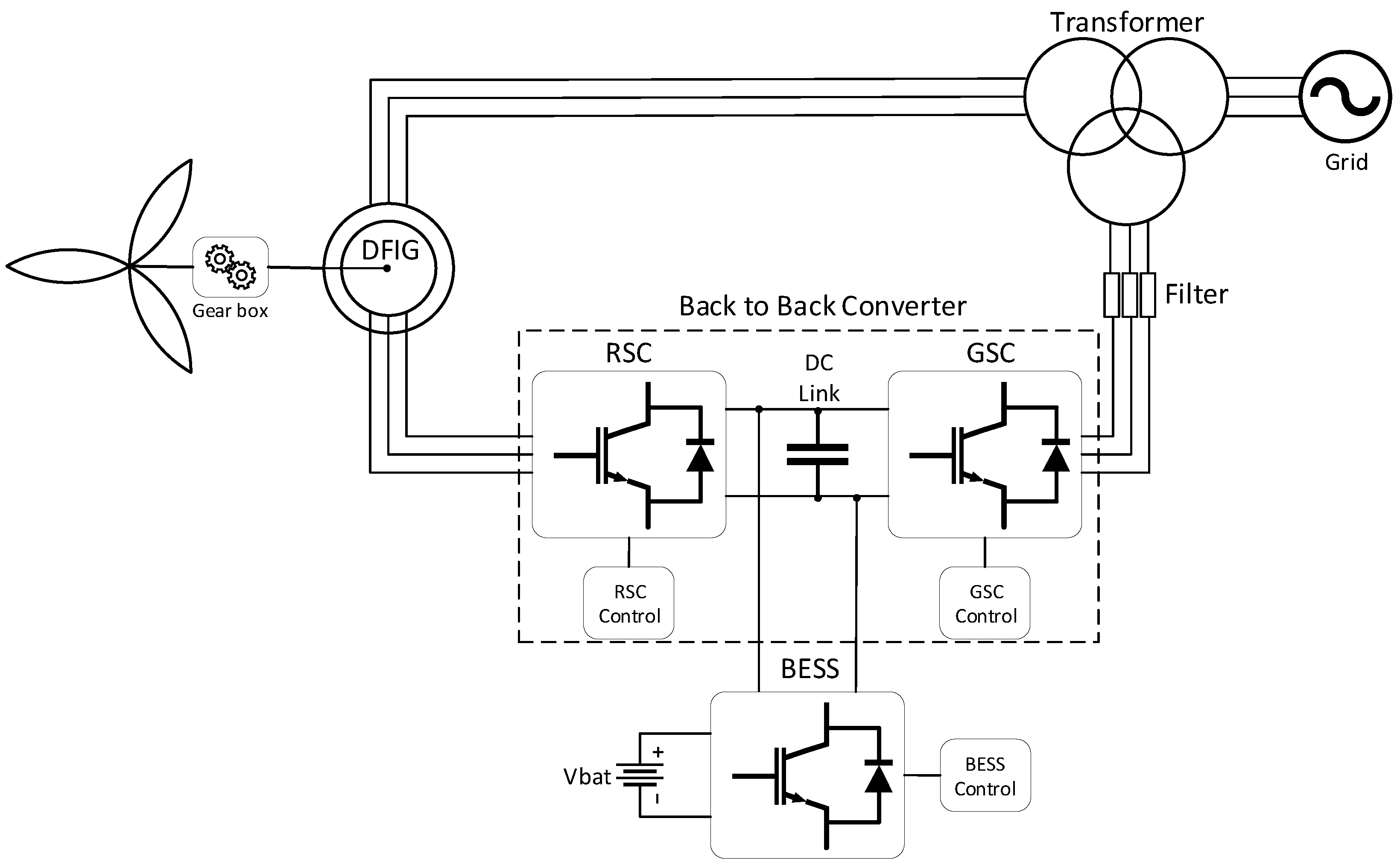
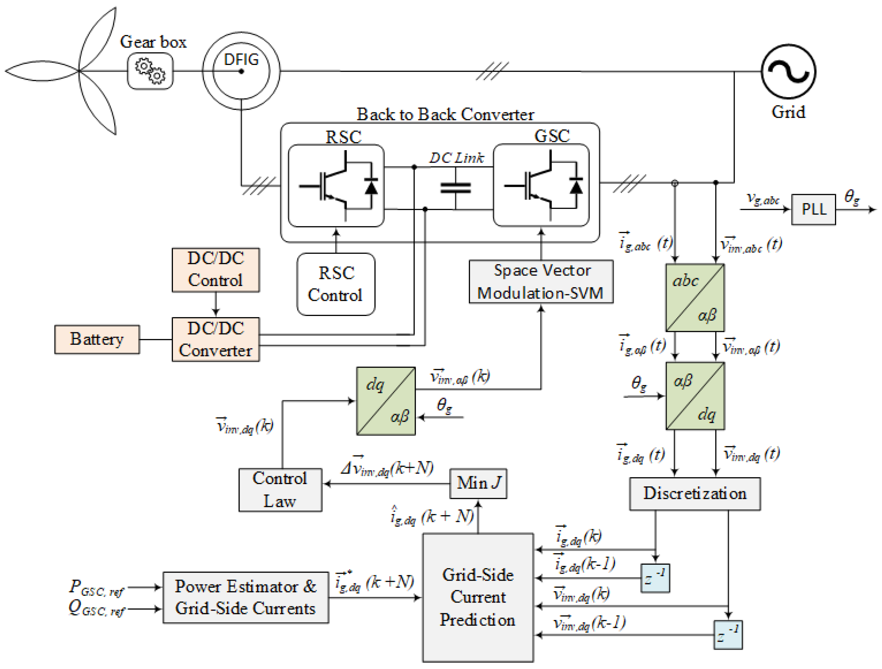
2.1. Overview of the Interconnection of a DFIG to a Microgrid

The connection of a DFIG-based wind turbine to a microgrid is shown in Figure 2.
The stator of the DFIG is directly connected to the grid, whilst its rotor is interfaced by a B2B converter. The converter that is directly connected to the rotor terminal is called the rotor side converter (RSC) and the converter that is connected to the microgrid is called the grid side converter (GSC). In a typical DFIG control system, the RSC is responsible for following the MPPT algorithm while the GSC is in charge of regulating the DC link voltage.
To enable frequency support capabilities through the GSC, a BESS can be incorporated into the DC link of the B2B converter and inherits the responsibility of controling the DC voltage. In this scenario, the function of the GSC is to manage the power that should be exchanged with the grid according to the needs of both the microgrid and BESS system. This configuration provides a communication-free strategy that links the response of the BESS to the GSC power through the voltage in the B2B converter capacitor.

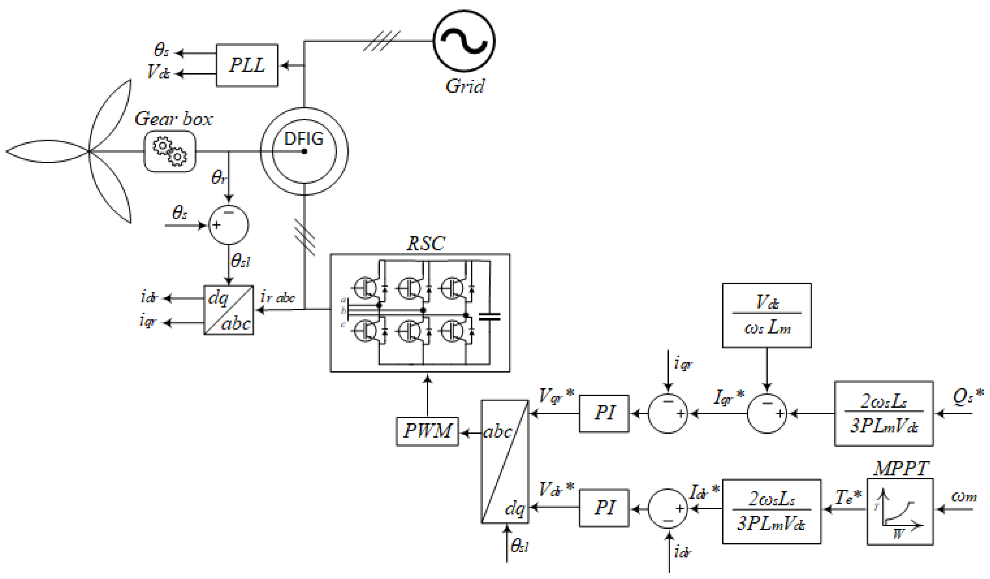
2.2. Rotor Side Dynamics and Control

Two basic strategies are used for the rotor side converter (RSC) control in DFIG wind energy applications [36,37] and both of them are based on the synchronous reference (or dq) frame. The first strategy uses the fact that the stator flux is oriented with the q-axis and is called the stator flux orientation control (SFOC) strategy. The other strategy is called the stator voltage orientation control (SVOC) strategy, which uses the alignment between the stator voltage and the d-axis [37]. The second orientation strategy is represented by Equation (1):
V q s = 0 , V d s = V s
The rotor’s angle position θ r and the stator’s angle position θ s are both measured with respect to the stator reference frame. In induction motors, the slip angle θ s l is the resulting angle difference between the stator and the rotor voltage vector, as defined by Equation (2):
θ s l = θ s θ r
Equation (2) allows us to make transformations between the abc and dq reference frames, as is depicted in Figure 3 in which the RSC control can be seen:
An MPPT optimal torque control can be achieved to obtain the maximum power operation of the DFIG by considering the fact that electromagnetic torque is proportional to angular speed ( T e ω m ). The torque reference and the optimal torque coefficient K o p t can be measured using the rotor speed and the equivalent DFIG circuit parameters. These estimations are represented by Equation (3), as follows:
T e * = K o p t · ω m 2
where T e is the electromagnetic torque, ω m is the mechanical speed of the rotor and K o p t is the optimal coefficient for the torque.
The electromagnetic torque can be estimated by means of Equation (4):
K o p t = 1 2 · G 3 · ρ · π · R 5 · C p m a x λ o p t 3
where G is the gearbox transformation ratio, ρ is the air density, R is the turbine radius, C p m a x is the maximum turbine power coefficient and λ o p t is the optimum tip speed ratio.
Previous works have considered the role of DFIGs in frequency regulation through RSCs in microgrids and weak power grids [38,39]. In spite of this, MPPT operation can be compromised and system efficiency can be decreased.

2.3. Grid Side Dynamics and Control

The GSC model can be seen in detail in [40] and it can be represented in the d q frame by Equation (5):
v i n v , d q = R g i g , d q + L g d i g , d q d t + v g , d q + j ω g L g i g , d q
where R g and L g are the equivalent resistance and inductance of a power grid modeled as a RL network and ω g is the angular speed of the grid voltages and currents.
It is assumed that the synchronous reference frame is aligned with the phase a of the grid voltage. In this scenario, the components of the voltage vector are given as v g , d = v g and v g , q = 0 . Following this assumption, the active ( P G S C ) and reactive ( Q G S C ) power that is exchanged with the grid can be written as:
P G S C = 3 2 v g , d i g , d
Q G S C = 3 2 v g , d i g , q
Using the Laplace transformation, Equation (5) can be expressed as follows:
v i n v , d q ( s ) = R g i g , d q ( s ) + L g s i g , d q ( s ) + v g , d q ( s ) + j ω g L g i g , d q ( s ) i g , d q ( s ) v i n v , d q ( s ) v g , d q ( s ) = 1 R g + L g s + j ω g L g
Equation (8) introduces the open loop model of the grid side converter.

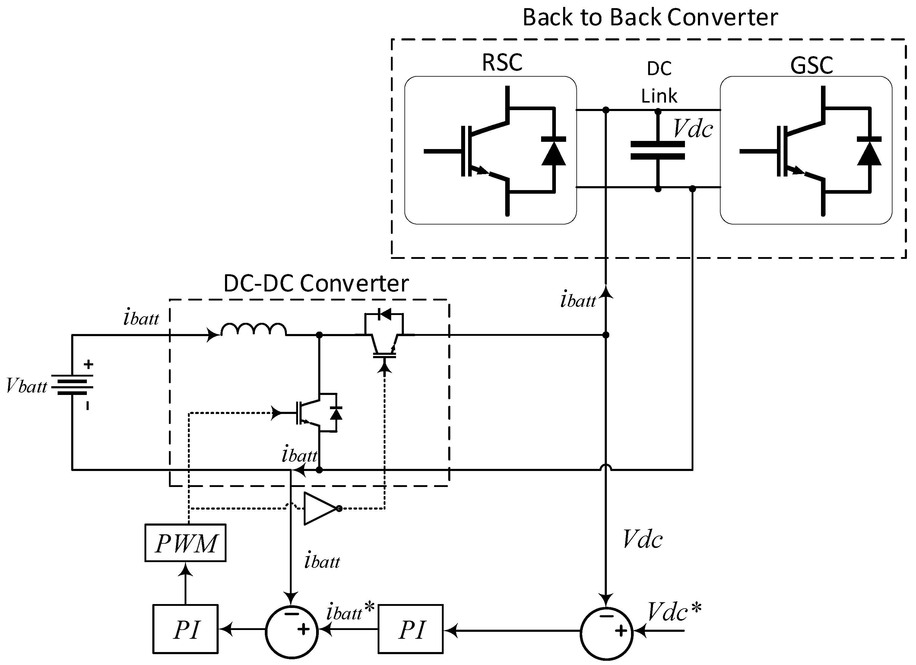
2.4. DC Voltage Dynamics and Control

In this work, we adopted a BESS in parallel with the DC link capacitor of a B2B converter that was interfaced by a buck–boost converter to provide the energy storage needed to support the frequency response of the microgrid, as seen in Figure 4 [7,8,41,42]. One advantage of connecting the BESS directly to the DC link is the DC nature of the BESS current, which avoided the need for the use of an extra DC–AC converter. When using this connection topology, the control objective of the system was to regulate the DC circuit voltage so that the BESS could inject or absorb the active power needed to support the frequency of the grid directly into the DC link without a communication system.
A model for the DC circuit voltage was obtained by observing the power balance in the DC link:
P D C = P R S C P G S C P b a t t
where P D C is the power exchanged by the DC link capacitor and the DC link and P R S C , P G S C and P b a t t are the power injected by the RSC, the GSC and the BESS into the DC link, respectively. The system (9) could be rewritten as:
C d V D C d t = i b a t t P R S C V D C P G S C V D C
The structure of the model (10) suggests that P R S C and P G S C can be considered as disturbances to the model, whilst i b a t t can be used to steer V D C towards its desired reference V D C * . Therefore, the control structure of Figure 4 could be used.
The control scheme for the DC voltage employed cascaded PI controllers. The inner loop was responsible for ensuring that the BESS current i b a t t followed its trajectory i b a t t * , which was generated by the outer loop controller. On the other hand, the trajectory i b a t t * was generated by the outer PI controller to regulate the DC link voltage.

2.5. Frequency Support from the Grid Side Converter

The conventional controls for DFIG-based wind turbines target the maximization of the power extracted from the wind by following MPPT schemes. When following an MPPT, the wind turbine behaves as a constant current source in short time intervals and is not able to react to changes in the microgrid. Therefore, to enable frequency support capabilities, the conventional controls of DFIGs must be modified.
When modifications are performed on the RSC control, then the wind turbine ceases to extract the maximum wind power for the duration of the disturbance and until the system reaches steady-state. Two popular alternatives for frequency support by modifying the RSC control are deloading and the inertial response using the energy stored in the turbine’s rotor. Deloading consists of maintaining an active power reserve at all times by deliberately operating away from the MPP. The inertial response consists of extracting the mechanical energy stored in the turbine’s rotor and injecting it into the microgrid following a frequency disturbance. After the power injection, the rotor slows down and must recover MPP operation afterward, which could cause a secondary disturbance in the microgrid.
By connecting a BESS to the DC link and modifying the GSC control to manage the power injected by the BESS, a DFIG-based wind turbine is able to participate in frequency support without compromising MPPT operation [7,8]. The reference value for the GSC active power P G S C * is obtained from a frequency droop given by:
P G S C * = R d ( f f r e f )
where R d is the considered droop coefficient, f is the measured microgrid frequency and f r e f is the electric grid rated frequency.
Assuming a balanced system, the trajectory i g , d * is then obtained by:
i g , d * = 2 P G S C * 3 v g , d = 2 R d ( f f r e f ) 3 v g , d
In this work, a GPC controller was implemented in a GSC to track the time varying i g , d * trajectory resulting from a frequency error to enable the injection of active power to support the microgrid frequency. The GPC that was embedded in the GSC is described in the next section.

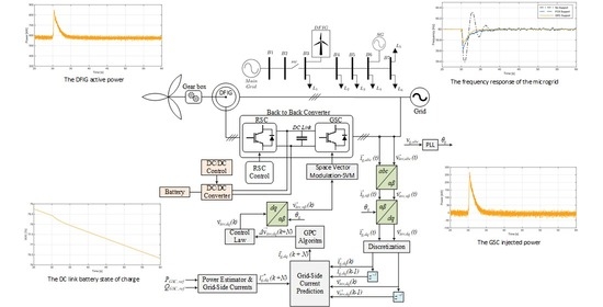
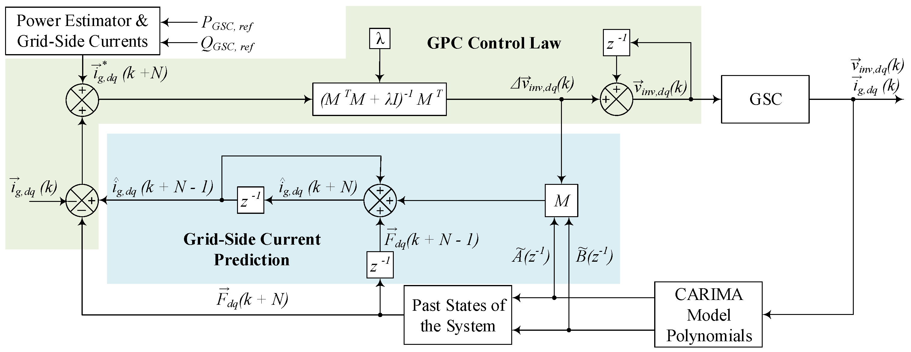
3. Generalized Predictive Controller Applied to the Grid Side Converter

GPCs belong to the class of MPCs, which means that they are a technique that relies on a system model for predictions and calculates the inputs to be applied based on optimization. A type of model that is frequently employed for GPC controllers is the controlled autoregressive moving average (CARIMA) model. This type of model allows for the simple calculation of the predictors and past states that are needed for the GPC algorithm.
In this work, a GPC was embedded into the GSC of a DFIG-based wind turbine, as shown in Figure 5, to track the time varying active power reference that enabled the participation of the wind turbine in the frequency support of a microgrid. As seen in Section 2, when considering a balanced network, the active power exchanged by the GSC and the microgrid was associated with the i g , d component of the converter current and the reactive power was associated with the component i g , q . Therefore, a model of the GSC currents needed to be obtained to develop a controller that was capable of following a time varying active power reference.
A CARIMA model for the GSC currents could be obtained after the discretization of the system’s continuous time model described in Equation (13). The starting point of the derivation of this model was the continuous time transfer function of Equation (5). By considering the coupling term between the i g , d and i g , q components as a disturbance, the continuous time transfer function between v i n v , d and i g , d could be written as:
G i g , d ( s ) = 1 R g + L g s = 1 L g 1 s + R g L g = I g , d ( s ) V i n v , d ( s )
By discretizing the transfer function (13) using the impulse invariant method [43], the following Z-transform of the model could be obtained:
H i g , d ( z 1 ) = T L g 1 1 e ( R g / L g T ) z 1
By following the procedure described in [28,32,44], the following CARIMA model was obtained:
A ˜ ( z 1 ) i g , d ( k ) = B ˜ ( z 1 ) u ( k 1 )
with polynomials:
A ˜ ( z 1 ) = 1 + a ˜ 1 z 1 + a ˜ 2 z 2
B ˜ ( z 1 ) = b ˜ 0 z 1 + b ˜ 1 z 2 .
whose coefficients are a ˜ 1 = ( 1 + e ( R g / L g T ) ) , a ˜ 2 = e ( R g / L g T ) , b ˜ 0 = T / L g and b ˜ 1 = T / L g .
By using the CARIMA model (15), it was possible to formulate a predictor for the GSC currents. Typically, the predictors for i ^ g , d and i ^ g , q are obtained using an incremental form, as seen in [28,32]. This means that instead of directly calculating the control input v i n v , d q ( k ) , the incremental values δ v i n v , d and δ v i n v , q are calculated by the GPC algorithm.
The general form for the current predictors was divided into two parts: the first was a function of δ v i n v , d ( k + j ) and δ v i n v , q ( k + j ) ( j > = 0 ) and was related to the future inputs of the system; the second was expressed as a function of F d q , which represented the past values of the system. The predictor was then used to obtain an estimation of the future values of the state variables i g , d q over a control horizon N. The first predictor for the sample k + 1 could be written as:
i ^ g , d q ( k + 1 ) = g 0 Δ v i n v , d q ( k ) ± s 0 Δ v i n v , d q ( k ) + i g , d q ( k ) + F d q ( k )
and the process was repeated until the prediction horizon at time k + N was reached:
i ^ g , d q ( k + N ) = g n 1 Δ v i n v , d q ( k + N 1 ) ± s n 1 Δ v i n v , d q ( k + N 1 ) + i ^ g , d q ( k + N 1 ) + F d q ( k + N 1 )
The coefficients g i and s i in (18) and (19) are given by (20) and (21), respectively. These were obtained from the step response of the system and the cross-coupling ( ω g L g ) term [32]:
g 0 = b 0 , g 1 = b 1 a 1 b 0 , , g m = a 1 g m 1 a 2 g m 2 b 0 ω g L g s m 2 b 1 ω g L g s m 3
s 0 = 0 , s 1 = b 0 ω g L g g 0 , s 2 = a 1 s 0 + b 1 ω g L g g 0 , s m = a 1 s m 1 a 2 s m 2 + b 0 ω g L g g m + b 1 ω g L g g m 1
The past states of the system F d q had to be updated at each time step according to the following procedure:
F d ( k + 1 ) = a 1 F d ( k ) a 2 F d ( k 1 ) + b 0 ω g L g F q ( k ) + b 1 ω g L g F q ( k 1 )
F q ( k + 1 ) = a 1 F q ( k ) a 2 F q ( k 1 ) b 0 ω g L g F d ( k ) b 1 ω g L g F d ( k 1 )
The update process of past states was repeated until the prediction horizon was reached:
F d ( k + N ) = a 1 F d ( k + N 1 ) a 2 F d ( k + N 2 ) + b 0 ω g L g F q ( k + N 1 ) + b 1 ω g L g F q ( k + N 2 )
F q ( k + N ) = a 1 F q ( k + N 1 ) a 2 F q ( k + N 2 ) b 0 ω g L g F d ( k + N 1 ) b 1 ω g L g F d ( k + N 2 )
Finally, the predictors from (18) to (19) could be rewritten by:
i ^ g , d ( k + 1 ) i ^ g , d ( k + N ) i ^ g , q ( k + 1 ) i ^ g , q ( k + N ) = G S S G Δ v i n v , d ( k ) Δ v i n v , q ( k ) + F d ( k ) F d ( k + N 1 ) F q ( k ) F q ( k + N 1 ) + i ^ g , d ( k ) i ^ g , d ( k + N 1 ) i ^ g , q ( k ) i ^ g , q ( k + N 1 )
where G = [ g 0 g m 1 ] T and S = [ s 0 s m 1 ] T .
To obtain the control inputs to be applied to the GSC at the instant k, the following optimization problem needed to be solved:
J = min j = 1 N [ i ^ g , d q ( k + j ) i ¯ g , d q ( k + j ) ] T [ i ^ g , d q ( k + j ) i ¯ g , d q ( k + j ) ] + Δ i n v , d q ( k ) T λ I Δ i n v , d q ( k )
where i ¯ g , d q ( k + j ) indicates the future values of the current trajectory, λ is the weighting factor and N is the control horizon.
Then, the incremental control inputs Δ v i n v , d q were calculated by solving the optimization problem as:
Δ v i n v , d ( k ) Δ v i n v , q ( k ) = ( M T M + λ I ) 1 M T i g , d * ( k + 1 ) i g , d * ( k + N ) i g , q * ( k + 1 ) i g , q * ( k + N ) F d ( k ) F d ( k + N ) F q ( k ) F q ( k + N ) i g , d ( k ) i ^ g , d ( k + N 1 ) i g , q ( k ) i ^ g , q ( k + N 1 )
where M is given by:
M = G S S G
From (28), the voltage that should be applied to the GSC was given by:
v i n v , d q ( k ) = v i n v , d q ( k 1 ) + Δ v i n v , d q ( k )
The process was then repeated at each sampling time. The GPC algorithm applied to the GSC that was described in this section is summarized in Figure 6.

4. Simulations and Results
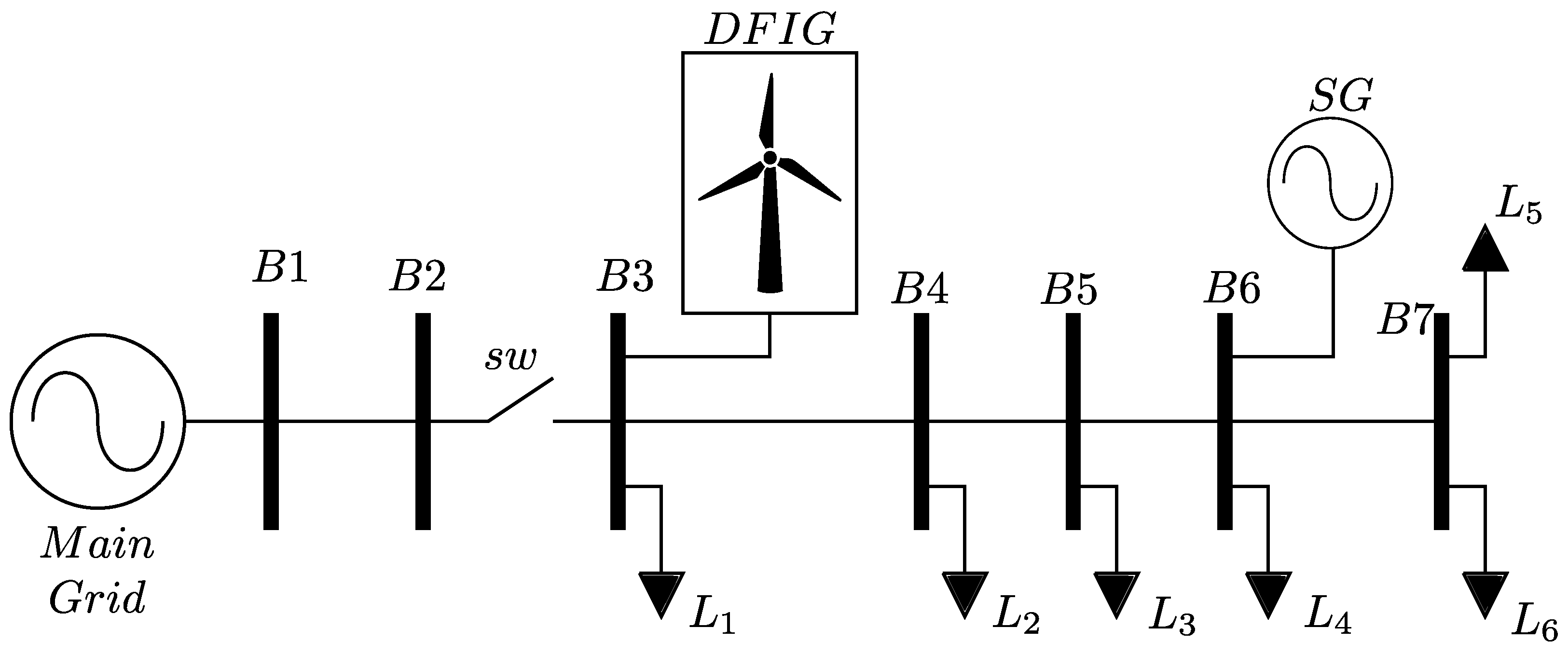
This section presents the simulations and results of this work. In Section 4.1, the test system and the studied conditions are described and the simulation results are shown in Section 4.2.

4.1. Test System

The 7-bus test system that was simulated in this work is shown in Figure 1. The 5-bus microgrid was connected to the electric grid through the switch sw that is indicated in the figure. When the switch was on, the microgrid operated in grid-connected mode; otherwise, it operated in islanded mode. Despite the DFIG being connected to B3, where the switch to the main grid was also connected, this is not a necessary condition for the proposed method. The DFIG could then be connected to any bus of the microgrid. This 5-bus microgrid topology was considered to allow a comparison to the FCS controller that was proposed in [8].
The synchronous generator of the microgrid had a 3.3 MVA installed capacity and its turbine was modeled to present the characteristics of a small gas turbine with a 5% droop. The load values are shown in Table 1. The loads were simulated as constant power loads. In the case of the adoption of frequency-dependent loads, the power demand would change according to their model settings and would impact the power balance in the microgrid differently for each considered scenario. Hence, by considering constant power loads, it was possible to evaluate the potential of the proposed control strategy in improving the frequency response of the islanded microgrid.
The wind turbine was equipped with a DFIG, the parameters of which are presented in Table 2.
To simulate a situation in which the microgrid demanded frequency support from the DFIG, the following scenario was considered. At first, the switch was turned on, meaning that the microgrid was operating in grid-connected mode. Then, the switch was suddenly turned off at t = 30 s, resulting in a transition to islanded mode. When the switch was turned off, there was an active power mismatch between the microgrid’s power demand and the power being generated by the DFIG and the synchronous generator, thus creating a frequency transient.
During this frequency transient, a power reference was generated to the GSC, which was based on the frequency error provided by (11) with the droop constant R p = 3%. Hence, the goal of the proposed GPC controller was to track this power reference in order to support the grid. The GPC parameters were the control horizon N = 3 and the weighting control factor λ = 0.008. The tuning of the weighting factor was obtained empirically for this application. We refer the reader to [45,46] for methods on how to obtain the optimal values for λ . The GSC voltage that was generated by the GPC was synthesized by a PWM scheme with a carrier frequency of 10 kHz.
To validate the proposed GPC control scheme for improving the microgrid’s frequency response, three wind speed conditions were chosen: v = 8 m/s (sub-synchronous operation), v = 11 m/s (rated speed operation) and v = 14 m/s (super-synchronous operation. To show the importance of the frequency support from the GSC, a scenario in which the DFIG did not provide frequency support was also simulated as a benchmark. Moreover, an FCS based on [20] with a fixed droop coefficient R p = 3% and a fixed sampling time of 0.05 ms (20 kHz) was also implemented to provide a comparison to another existing MPC that has been used for GSC frequency response.
It is important to highlight that despite using the test system shown in Figure 1, the proposed method is not limited to this microgrid topology. The frequency support relies on a communication-free effort between a BESS and a grid-connected converter that has an active power reference with a component given by (11). Hence, whenever there is a frequency error in the microgrid, the proposed strategy generates an active power reference for the GPC to track. The proposed method is also not bus-dependent, meaning that the resource to provide frequency support does not need to be connected to bus B3, which is where the microgrid is connected to the switch that manages grid-connected operation. Moreover, the proposed frequency support methodology could be applied to different wind turbine technologies, such as a permanent magnet synchronous generator (which are reliant on a B2B converter) or a PV panel. In these cases, however, the active power reference would have an additional component to (11) to inject power into the grid, which would correspond to the MPP operation. The choice of the DFIG was selected to enable the comparison to [8], in which a similar microgrid structure was considered alongside a FCS-MPC approach, and the choice of a single resource to provide frequency response was justified by the need to evaluate the performance of the proposed strategy.

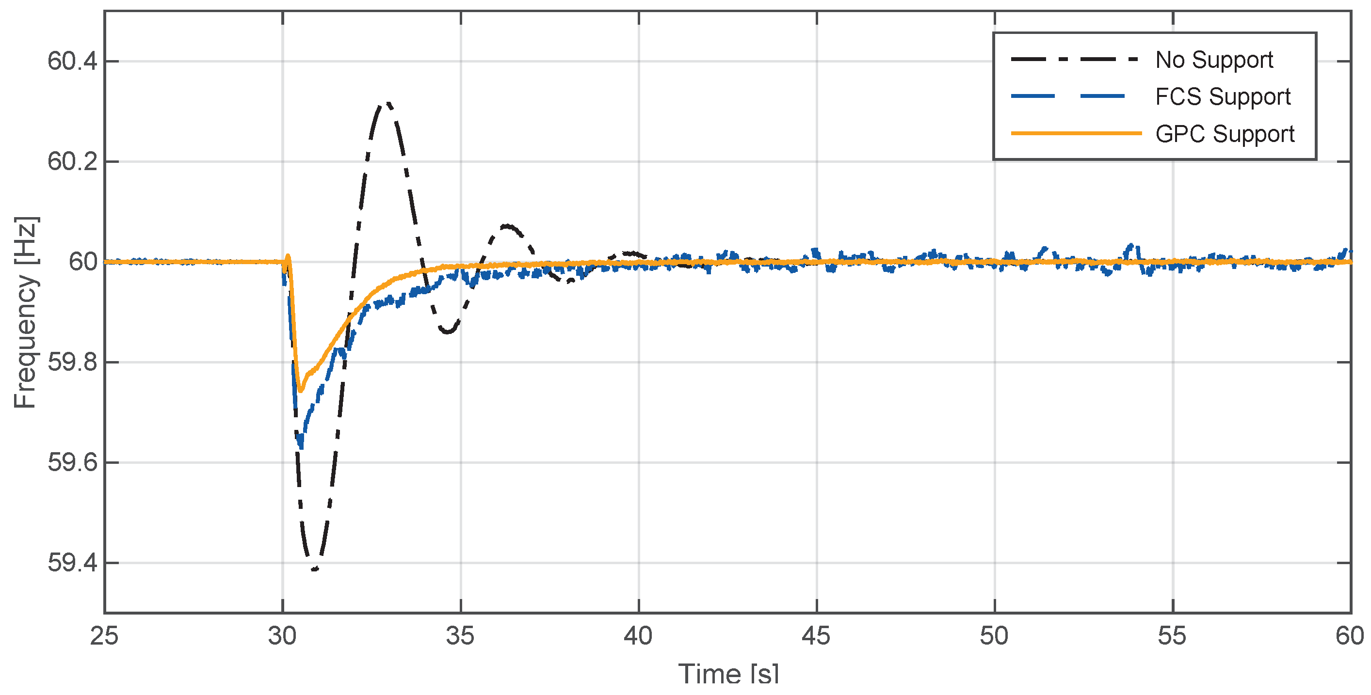
4.2. Simulation Results

4.2.1. Sub-Synchronous Operation

The frequency response of the microgrid during the transition from grid-connected to island mode when the DFIG was operating in the sub-synchronous region is shown in Figure 7. When DFIGs are not equipped with frequency response capabilities, the full responsibility for frequency control falls to the synchronous generator of the microgrid.
As shown in Figure 7, the microgrid frequency oscillated due to the power imbalance that was caused by the sudden islanding and then settled at the its rated value. However, when the GSC control was modified to inject the power available into the BESS, it was possible to mitigate the frequency oscillations and improve the frequency nadir, which was the lowest value sustained during the frequency transient.
By implementing the frequency support capability using the FCS, the same benefits of mitigating frequency oscillations and improving the frequency nadir could be achieved. Nevertheless, between the two MPC strategies that were implemented to enable frequency support from the GSC, the proposed GPC controller presented an increased frequency nadir value compared to the FCS controller.
The power response from the DFIG is shown in Figure 8. When the power imbalance occurred, the deviation in frequency promped the GSC to inject power into the grid as the GPC that was embedded in the GSC ensured the tracking of the time varying power reference, as shown in Figure 9. The GSC was able to inject over 250 kW of active power to support the frequency.
The power reserve in the considered system was the BESS, the SOC of which is shown in Figure 10. As shown in [8], deloading the DFIG might not be enough to provide sufficient power reserves to deal with such disturbances caused by islanding, thereby justifying the employment of a BESS in the DC link to provide frequency support. Moreover, as Figure 10 suggests, the management of the stored power while regulating the DC voltage was important so that when a disturbance occurred, the system was capable of providing enough active power to help to improve frequency stability.

4.2.2. Rated Speed Operation

In this section, the frequency disturbance caused by the sudden islanding of the microgrid is studied when the DFIG was operating in its rated speed condition. Figure 11 shows the frequency response of the microgrid with and without frequency support from the DFIG.
For this scenario, the proposed GPC controller also presented a better performance in terms of oscillations compared to the scenario in which the DFIG did not have frequency response capabilities. Comparing the MPC controllers that were implemented, both the GPC and the FCS acted on mitigating the frequency oscillations and the improvement of the frequency nadir when considering the base scenario in which the GSC did not provide frequency support. The GPC controller was able to improve the frequency nadir more compared to the FCS and helped the microgrid return to the rated frequency faster.
When equipped with the proposed control strategy, the DFIG injected power into the microgrid after the disturbance, as seen in Figure 12. The power that was injected into the microgrid following the time varying power reference that was tracked by the GPC implemented in the GSC is shown in Figure 13. The GSC was able to provide over 350 kW of active power during the disturbance, which was drawn from the BESS.
The SOC of the DC link BESS is shown in Figure 14. It can be seen that in the moment that the islanding occurred, the SOC decreased in response to the active power that was injected by the GSC into the microgrid.

4.2.3. Super-Synchronous Operation

Finally, in this section, the frequency response of the microgrid when the DFIG was operating in the super-synchronous regions is studied. The frequency response of the microgrid is shown in Figure 15, in which the simulation results with and without frequency support from the DFIG are presented.
As seen in Figure 15, the embedding of a GPC that was capable of tracking the time varying active power reference given by a frequency droop improved the frequency response of the system. Compard to the scenario without frequency support from the DFIG, the oscillations were mitigated and the frequency nadir was improved. Moreover, the frequency support capabilities provided by both of the implemented MPC strategies were able to mitigate frequency oscillations and improve the frequency nadir. The GPC strategy also enabled a faster return and a higher frequency nadir compared to the FCS alternative.
The improvement of the frequency response was achieved through the injection of active power by the DFIG, as shown in Figure 16. At the moment of islanding, the DFIG was able to inject nearly 200 kW of active power that was drawn from the BESS (Figure 17). The SOC of the BESS following the active power injection is shown in Figure 18.

5. Conclusions

In this work, we presented a GPC that could enable the participation of a DFIG-based wind turbine in the frequency support of a microgrid. The transition to islanded operation was studied for three DFIG operating conditions (sub-synchronous, super-synchronous and rated speed operation), in which the proposed control strategy was able to improve the frequency response of the microgrid. Comparing the proposed GPC strategy to a FCS controller, the GPC enabled a faster return to the rated frequency while also improving the frequency nadir. By increasing the value of the frequency nadir (the lowest frequency value during the disturbance) and mitigating frequency oscillations, the proposed controller can be considered as a suitable solution for enabling frequency support from DFIG-based wind turbines in microgrids.

Author Contributions

Conceptualization, L.F.N.L., J.S.S.-C. and A.J.S.F.; methodology, C.E.P.C., J.S.S.-C., L.F.N.L. and A.J.S.F.; model development, C.E.P.C., L.F.N.L., J.S.S.-C. and A.J.S.F.; simulations, C.E.P.C., L.F.N.L. and J.S.S.-C.; writing—original draft preparation, C.E.P.C., L.F.N.L., J.S.S.-C. and A.J.S.F.; writing—review and editing, C.E.P.C., L.F.N.L., J.S.S.-C. and A.J.S.F. All authors have read and agreed to the published version of the manuscript.

Funding

This research was funded by the Coordenação de Aperfeiçoamento de Pessoal de Nível Superior – Brasil CAPES (Project 001), the National Council for Scientific and Technological Development (CNPq) (grant number Process 405757/2018-2) and the São Paulo Research Foundation (Fapesp grant#2021/10421-0).

Conflicts of Interest

The authors declare no conflict of interest. The funders had no role in the design of the study, in the collection, analyses or interpretation of data, in the writing of the manuscript or in the decision to publish the results.

Abbreviations

The following abbreviations are used in this manuscript:
ACAlternating Current
B2BBack-to-Back Converter
BESSBattery Energy Storage System
CARIMAControlled Autoregressive Moving Average
DCDirect Current
DFIGDoubly Fed Induction Generator
FCSFinite Control Set
GPCGeneralized Predictive Control
GSCGrid Side Converter
MPCModel Predictive Control
MPPMaximum Power Point
MPPTMaximum Power Point Tracking
PLLPhase-Locked Loop
PWMPulse Width Modulation
RERRenewable Energy Resource
RSCRotor Side Converter
SOCState of Charge
SGSynchronous Generator
VSCVoltage Source Converter

References

  1. Ahmed, M.; Meegahapola, L.; Vahidnia, A.; Datta, M. Stability and control aspects of microgrid Architectures–A comprehensive review. IEEE Access 2020, 8, 144730–144766. [Google Scholar] [CrossRef]
  2. Farrokhabadi, M.; Cañizares, C.A.; Simpson-Porco, J.W.; Nasr, E.; Fan, L.; Mendoza-Araya, P.A.; Tonkoski, R.; Tamrakar, U.; Hatziargyriou, N.; Lagos, D.; et al. Microgrid stability definitions, analysis, and examples. IEEE Trans. Power Syst. 2019, 35, 13–29. [Google Scholar] [CrossRef]
  3. Lasseter, B. Microgrids [distributed power generation]. In Proceedings of the 2001 IEEE Power Engineering Society Winter Meeting, Columbus, OH, USA, 28 January–1 February 2001. [Google Scholar]
  4. Hatziargyriou, N.; Asano, H.; Iravani, R.; Marnay, C. Microgrids. IEEE Power Energy Mag. 2007, 5, 78–94. [Google Scholar] [CrossRef]
  5. Lasseter, R.H.; Chen, Z.; Pattabiraman, D. Grid-forming inverters: A critical asset for the power grid. IEEE J. Emerg. Sel. Top. Power Electron. 2019, 8, 925–935. [Google Scholar] [CrossRef]
  6. Yang, D.; Kim, J.; Kang, Y.C.; Muljadi, E.; Zhang, N.; Hong, J.; Song, S.H.; Zheng, T. Temporary frequency support of a DFIG for high wind power penetration. IEEE Trans. Power Syst. 2018, 33, 3428–3437. [Google Scholar] [CrossRef]
  7. Gomez, L.; Grilo, A.P.; Salles, M.; Sguarezi Filho, A. Combined control of DFIG-based wind turbine and battery energy storage system for frequency response in microgrids. Energies 2020, 13, 894. [Google Scholar] [CrossRef] [Green Version]
  8. Gomez, L.A.; Lourenço, L.F.; Grilo, A.P.; Salles, M.B.; Meegahapola, L.; Sguarezi Filho, A.J. Primary frequency response of microgrid using doubly fed induction generator with finite control set model predictive control plus droop control and storage system. IEEE Access 2020, 8, 189298–189312. [Google Scholar] [CrossRef]
  9. Datta, U.; Shi, J.; Kalam, A. Primary frequency control of a microgrid with integrated dynamic sectional droop and fuzzy based pitch angle control. Int. J. Electr. Power Energy Syst. 2019, 111, 248–259. [Google Scholar] [CrossRef]
  10. Zhao, J.; Lyu, X.; Fu, Y.; Hu, X.; Li, F. Coordinated Microgrid Frequency Regulation Based on DFIG Variable Coefficient Using Virtual Inertia and Primary Frequency Control. IEEE Trans. Energy Convers. 2016, 31, 833–845. [Google Scholar] [CrossRef]
  11. Tan, Y.; Meegahapola, L.; Muttaqi, K.M. A Suboptimal Power-Point-Tracking-Based Primary Frequency Response Strategy for DFIGs in Hybrid Remote Area Power Supply Systems. IEEE Trans. Energy Convers. 2016, 31, 93–105. [Google Scholar] [CrossRef]
  12. Gholamrezaie, V.; Dozein, M.G.; Monsef, H.; Wu, B. An Optimal Frequency Control Method Through a Dynamic Load Frequency Control (LFC) Model Incorporating Wind Farm. IEEE Syst. J. 2018, 12, 392–401. [Google Scholar] [CrossRef]
  13. Han, Y.; Ha, J. Droop Control Using Impedance of Grid-Integrated DFIG within Microgrid. IEEE Trans. Energy Convers. 2019, 34, 88–97. [Google Scholar] [CrossRef]
  14. Van de Vyver, J.; De Kooning, J.D.M.; Meersman, B.; Vandevelde, L.; Vandoorn, T.L. Droop Control as an Alternative Inertial Response Strategy for the Synthetic Inertia on Wind Turbines. IEEE Trans. Power Syst. 2016, 31, 1129–1138. [Google Scholar] [CrossRef]
  15. Muljadi, E.; Gevorgian, V.; Singh, M.; Santoso, S. Understanding inertial and frequency response of wind power plants. In Proceedings of the 2012 IEEE Power Electronics and Machines in Wind Applications, Denver, CO, USA, 16–18 July 2012; pp. 1–8. [Google Scholar] [CrossRef]
  16. Ahmadyar, A.S.; Verbič, G. Coordinated Operation Strategy of Wind Farms for Frequency Control by Exploring Wake Interaction. IEEE Trans. Sustain. Energy 2017, 8, 230–238. [Google Scholar] [CrossRef]
  17. Li, Y.; Xu, Z.; Østergaard, J.; Hill, D.J. Coordinated Control Strategies for Offshore Wind Farm Integration via VSC-HVDC for System Frequency Support. IEEE Trans. Energy Convers. 2017, 32, 843–856. [Google Scholar] [CrossRef] [Green Version]
  18. Ahmadyar, A.S.; Verbič, G. Control strategy for optimal participation of wind farms in primary frequency control. In Proceedings of the 2015 IEEE Eindhoven PowerTech, Eindhoven, The Netherlands, 29 June–2 July 2015; pp. 1–6. [Google Scholar] [CrossRef]
  19. Hu, Y.; Wu, Y. Approximation to Frequency Control Capability of a DFIG-Based Wind Farm Using a Simple Linear Gain Droop Control. IEEE Trans. Ind. Appl. 2019, 55, 2300–2309. [Google Scholar] [CrossRef]
  20. Gomez, L.; Lourenço, L.; Salles, M.; Grilo, A. Frequency support by grid connected DFIG-based wind farms. In Design, Analysis, and Applications of Renewable Energy Systems; Elsevier: Amsterdam, The Netherlands, 2021; pp. 481–496. [Google Scholar]
  21. Xu, Y.; Yang, D.; Huang, J.; Zhang, X.; Hua, L. Fast Stepwise Inertial Control Scheme of a DFIG for Reducing Second Frequency Drop. Appl. Sci. 2021, 11, 8259. [Google Scholar] [CrossRef]
  22. Vazquez, S.; Rodriguez, J.; Rivera, M.; Franquelo, L.G.; Norambuena, M. Model Predictive Control for Power Converters and Drives: Advances and Trends. IEEE Trans. Ind. Electron. 2017, 64, 935–947. [Google Scholar] [CrossRef] [Green Version]
  23. Sguarezi Filho, A.J. Model Predictive Control for Doubly-Fed Induction Generators and Three-Phase Power Converters; Elsevier: Amsterdam, The Netherlands, 2022. [Google Scholar]
  24. Mahmoud, M.S.; Oyedeji, M.O. Adaptive and predictive control strategies for wind turbine systems: A survey. IEEE/CAA J. Autom. Sin. 2019, 6, 364–378. [Google Scholar] [CrossRef]
  25. Sguarezi Filho, A.J.; Ruppert Filho, E. Model-Based Predictive Control Applied to the Doubly-Fed Induction Generator Direct Power Control. IEEE Trans. Sustain. Energy 2012, 3, 398–406. [Google Scholar] [CrossRef]
  26. Clarke, D.W.; Mohtadi, C.; Tuffs, P. Generalized predictive control Part I. The basic algorithm. Automatica 1987, 23, 137–148. [Google Scholar] [CrossRef]
  27. Clarke, D.W.; Mohtadi, C. Properties of generalized predictive control. Automatica 1989, 25, 859–875. [Google Scholar] [CrossRef]
  28. Zhang, L.; Norman, R.; Shepherd, W. Long-range predictive control of current regulated PWM for induction motor drives using the synchronous reference frame. IEEE Trans. Control Syst. Technol. 1997, 5, 119–126. [Google Scholar] [CrossRef]
  29. Bouzid, M.A.; Massoum, A.; Zine, S. Generalized Predictive Control of Standalone Wind Energy Generation System. Int. J. Renew. Energy Res. 2016, 6, 220–228. [Google Scholar]
  30. Zhang, Z.; Hui Fang, F.G.; Rodríguez, J.; Kennel, R. Multiple-Vector Model Predictive Power Control for Grid-Tied Wind Turbine System With Enhanced Steady-State Control Performance. IEEE Trans. Ind. Electron. 2017, 64, 6287–6298. [Google Scholar] [CrossRef]
  31. Kennel, R.; Linder, A.; Linke, M. Generalized predictive control (GPC)-ready for use in drive applications? In Proceedings of the 2001 IEEE 32nd Annual Power Electronics Specialists Conference, Vancouver, BC, Canada, 17–21 June 2011. [Google Scholar]
  32. Solís-Chaves, J.S.; Rodrigues, L.L.; Rocha-Osorio, C.; Sguarezi Filho, A.J. A long-range generalized predictive control algorithm for a DFIG based wind energy system. IEEE/CAA J. Autom. Sin. 2019, 6, 1209–1219. [Google Scholar] [CrossRef]
  33. Dias, S.V.; Silva, W.A.; Neto, T.R.; dos Reis, L.L.; Torrico, B.C.; Campos, J.C. Robust generalized predictive control applied to the mitigation of electromagnetic torque oscillations in a wind energy conversion system based on DFIG. In Proceedings of the 2016 IEEE Biennial Congress of Argentina, Buenos Aires, Argentina, 15–17 June 2016; pp. 1–6. [Google Scholar]
  34. Lunardi, A.S.; Solís-Chaves, J.S.; Filho, A.J.S. Predictive Direct Torque Control for a Squirrel Cage Induction Generator Grid Connected for Wind Energy Applications. IEEE Lat. Am. Trans. 2016, 14, 4454–4461. [Google Scholar] [CrossRef]
  35. Lunardi, A.; Conde, E.; Assis, J.; Meegahapola, L.; Fernandes, D.A.; Sguarezi Filho, A. Repetitive Predictive Control for Current Control of Grid-Connected Inverter under Distorted Voltage Conditions. IEEE Access, 2022; early access. [Google Scholar] [CrossRef]
  36. Eltigani, D.; Masri, S. Challenges of integrating renewable energy sources to smart grids: A review. Renew. Sustain. Energy Rev. 2015, 52, 770–780. [Google Scholar] [CrossRef]
  37. Wu, B.; Lang, Y.; Zargari, N.; Kouro, S. Power Conversion and Control of Wind Energy Systems; John Wiley & Sons: Hoboken, NJ, USA, 2011; Volume 76. [Google Scholar]
  38. Ramtharan, G.; Jenkins, N.; Ekanayake, J. Frequency support from doubly fed induction generator wind turbines. IET Renew. Power Gener. 2007, 1, 3–9. [Google Scholar] [CrossRef]
  39. Zhang, Z.S.; Sun, Y.Z.; Lin, J.; Li, G.J. Coordinated frequency regulation by doubly fed induction generator-based wind power plants. IET Renew. Power Gener. 2012, 6, 38–47. [Google Scholar] [CrossRef]
  40. Yazdani, A.; Iravani, R. Voltage-Sourced Converters in Power Systems; John Wiley & Sons: Hoboken, NJ, USA, 2010; Volume 34. [Google Scholar]
  41. Mesbahi, T.; Ouari, A.; Ghennam, T.; Berkouk, E.M.; Rizoug, N.; Mesbahi, N.; Meradji, M. A stand-alone wind power supply with a Li-ion battery energy storage system. Renew. Sustain. Energy Rev. 2014, 40, 204–213. [Google Scholar] [CrossRef]
  42. Xu, G.; Xu, L.; Morrow, J. Power oscillation damping using wind turbines with energy storage systems. IET Renew. Power Gener. 2013, 7, 449–457. [Google Scholar] [CrossRef]
  43. Dogan, I. Microcontroller Based Applied Digital Control; John Wiley & Sons: Hoboken, NJ, USA, 2006. [Google Scholar]
  44. Linder, A.; Kanchan, R.; Stolze, P.; Kennel, R. Model-based Predictive Control of Electric Drives; Cuvillier: Niedersachsen, Germany, 2010. [Google Scholar]
  45. Rodrigues, L.L.; Vilcanqui, O.A.; Murari, A.L.; Sguarezi Filho, A.J. Predictive power control for DFIG: A FARE-based weighting matrices approach. IEEE J. Emerg. Sel. Top. Power Electron. 2019, 7, 967–975. [Google Scholar] [CrossRef]
  46. Rodrigues, L.L.; Solís-Chaves, J.S.; Vilcanqui, O.A.; Sguarezi Filho, A.J. Predictive incremental vector control for DFIG with weighted-dynamic objective constraint-handling method-PSO weighting matrices design. IEEE Access 2020, 8, 114112–114122. [Google Scholar] [CrossRef]
Figure 1. The 7-bus test system containing a 5-bus microgrid comprising six loads, a DFIG and a small synchronous generator.
Energies 15 02562 g001
Figure 2. An overview of the connection of a DFIG-based wind turbine to a microgrid.
Energies 15 02562 g002
Figure 3. An overview of the RSC control diagram.
Energies 15 02562 g003
Figure 4. A block diagram of the DC link voltage control.
Energies 15 02562 g004
Figure 5. A block diagram of the proposed GPC control strategy being applied to a DFIG.
Energies 15 02562 g005
Figure 6. The GPC algorithm that was applied to the GSC of a DIFG.
Energies 15 02562 g006
Figure 7. The frequency response of the microgrid.
Energies 15 02562 g007
Figure 8. The DFIG active power.
Energies 15 02562 g008
Figure 9. The GSC injected power.
Energies 15 02562 g009
Figure 10. The DC link battery state of charge.
Energies 15 02562 g010
Figure 11. The frequency response of the microgrid.
Energies 15 02562 g011
Figure 12. The DFIG active power.
Energies 15 02562 g012
Figure 13. The GSC injected power.
Energies 15 02562 g013
Figure 14. The DC link battery state of charge.
Energies 15 02562 g014
Figure 15. The frequency response of the microgrid.
Energies 15 02562 g015
Figure 16. The DFIG active power.
Energies 15 02562 g016
Figure 17. The GSC injected power.
Energies 15 02562 g017
Figure 18. The DC link battery state of charge.
Energies 15 02562 g018
Table 1. The load values that were considered for the simulation.
LoadP (kW)Q (kVAr)LoadP (kW)Q (kVAr)
L 1 4015.6 L 4 15250
L 2 2000300 L 5 19564
L 3 29095 L 6 518170
Table 2. The parameters that were used in the simulation of the DFIG of the wind turbine.
ParameterValueParameterValue
Rated Power2 MWStator Resistance ( R s )0.023 p.u.
Stator Voltage (L-L)575 VStator Inductance ( L s )0.18 p.u.
Rotor Voltage (L-L)1075 VRotor Resistance ( R r )0.016 p.u.
DC voltage1050 VRotor Inductance ( L r )0.16 p.u.
Filter Resistance ( R g )0.003 p.u.Turbine Inertia Constant0.685 s
Filter Inductance ( L g )0.3 p.u.Friction0.1 p.u.
Publisher’s Note: MDPI stays neutral with regard to jurisdictional claims in published maps and institutional affiliations.

