1. Introduction
In recent years, much has been studied about switched systems. This subclass of hybrid systems is characterized by presenting a set of subsystems and a rule (function) that orchestrates the switching among them. Much of the interest is motivated by the fact that they present some intrinsic properties that can be explored to assure stability and a suitable performance for systems in several areas of engineering, see [
1,
2]. A great number of works in the literature is dedicated to the control design of state or output-dependent switching rules based on the Lyapunov theory. Reference [
3] presents design conditions for switched linear systems, while [
4,
5,
6] are dedicated to switched affine systems.
In power electronics, switched affine systems are used as models for DC–DC power converters. A widely known control technique is based on the adoption of classical controllers to regulate the duty-cycle of pulse-width modulation (PWM) signals, which are designed for a Linear Time-Invariant (LTI) averaged model that describes the behavior of the switched system for a specific operation point. However, treating this problem employing min-type switching strategies, as proposed in [
4,
7,
8], in the light of the Lyapunov theory, has been an advantageous control alternative from theoretical and practical viewpoints. These control methodologies are important since they explore the nonlinear and time-varying nature of the switched systems under consideration. Despite its importance, a deep analysis of these advantages and several aspects arising in practical implementations have not yet been fully explored.
One of these aspects concerns the switching frequency. Several available results, such as [
7,
9], suppose the possibility of an infinite switching frequency to assure asymptotic stability. This is not possible from a practical perspective due to physical limitations. To circumvent this problem, some references have proposed min-type switching strategies with limited frequency assuring practical stability of an equilibrium point (see [
4,
10,
11]) or asymptotic stability of an adequate limit-cycle (see [
12,
13]). However, an analysis of how this frequency varies concerning the operation point has never been made. When the switching frequency is constant and generally high, as is the case of PWM-based techniques, the power loss due to the switching is significant, leading to a lower efficiency mainly when the converter is not operating at full load [
14]. In this case, some techniques and algorithms have been proposed to improve the converter’s efficiency by varying the frequency according to the output power, such as [
15,
16,
17]. It is interesting to notice that in the case of min-type switching strategies the frequency variation is an intrinsic characteristic that will be fully analyzed in the present paper.
Another important aspect of practical implementations is the robustness property for changes in the operation point. Most of the control methodologies consider that the converter always operates in a specific equilibrium point. In the case of min-type switching strategies, such as [
5,
7], the robustness property does not exist or leads to a very conservative result. In this paper, we have generalized two well-known min-type switching strategies to make them robust concerning changes in the equilibrium points, removing the need for redesign. Moreover, to reduce steady-state errors, which are common in these control methodologies, some external control loops are proposed in the literature, for instance [
4,
8]. The idea of this external loop is to force the system to operate in a novel equilibrium point. In the present paper, we have adapted the proposal from [
8] to improve the performance of the overall system.
In summary, our main contributions are as follows:
We have analyzed, by means of simulation and experimental tests, some aspects of the min-type switching strategies proposed, as for instance, in [
4,
5,
7,
8]. Although these aspects are very important for practical implementations, they have not yet been fully explored in the literature. They concern the switching frequency variation and the performance in the transient and steady-state responses. Particularly, the former aspect is characteristic of the min-type switching controllers, which are not based on averaged systems and explore the nonlinear nature of the switched system under consideration. We have shown as the switching frequency of these controllers varies with the output voltage, indicating a possible power loss reduction compared to PWM-based techniques;
We have generalized the methodologies proposed in [
5,
7] to make them robust with respect to changes in the equilibrium points, which is a situation very common in practical implementations. These references have been adopted as a basis for generalization of several works in the literature, see, for instance, [
4,
18,
19]. As the change in the equilibrium point is taken into account during the design step, the performance in the transient and in the steady-state responses tends to be better when this situation occurs;
We have adapted the methodology proposed in [
8] to enhance the external control loop used for correcting the steady-state error.
The paper is structured as follows.
Section 2 presents the problem formulation and the control goal. The control techniques, as well as the theoretical enhancements related to robustness with respect to changes in the equilibrium points, are presented in
Section 3.
Section 4 is dedicated to provide the control parameters and the experimental build. Important features of the frequency variation and a proposal of an external loop to correct the steady-state error are also presented in this section.
Section 5 provides and discusses experimental results and, finally,
Section 6 summarizes the main aspects of the results and provides a perspective for future work.
A standard notation is used throughout. The set of real numbers is denoted by . The set contains the first N positive natural numbers. The transpose of a vector or a matrix X is identified by . The symbol denotes the trace function. The matrix represents the convex combination of the set , where belongs to the unitary simplex . The symbol indicates the switching function and denotes a matrix, such that . The symbol means the argument i of the function and inf stands for the infimum operator. For a real and symmetric matrix, () identifies it as positive (negative) definite. The square norm of a trajectory defined for all , is denoted by .
2. Problem Formulation
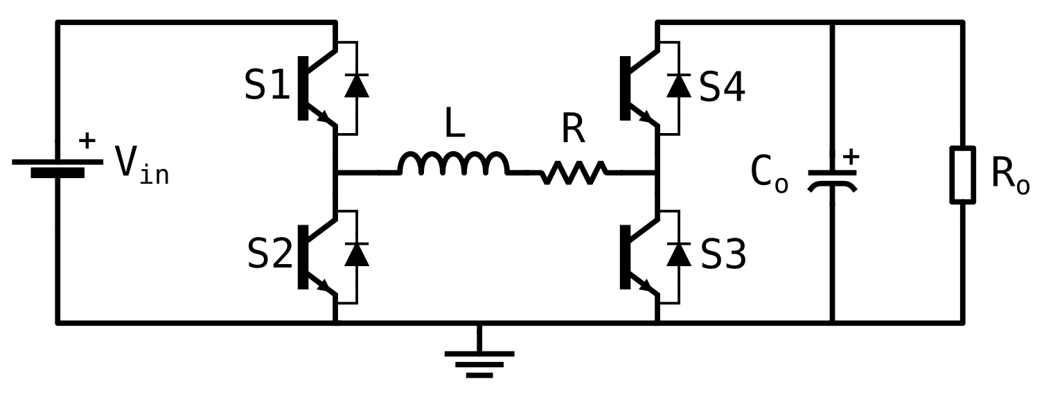
Consider a synchronous Buck–Boost converter whose topology is presented in
Figure 1. Defining the state variable
, the following continuous-time switched affine system expresses the dynamic model of this converter
where
is an arbitrary initial condition and
is the switching function that, at each instant of time, chooses one of the
N available subsystems.
In this circuit, each pair of switches
and
operates complementarily, that is, when
is closed,
is open, and vice versa. The same behavior occurs for the switches
and
. The state of the switches (open or closed) operating synchronously allows us to define
subsystems, being the first obtained when the switches
and
are active, while the second is obtained when the switches
and
are active, resulting in the following state-space models
The control goal is to design a state-dependent switching rule
in order to govern the state trajectories towards an equilibrium point
belonging to the set
of attainable ones.
Using the equation
obtained from (
3), we can determine the equilibrium current as a function of the desired output voltage
, as follows
Actually, for each voltage
, there are two possible values for the equilibrium current
. In (
4) the higher value was discarded, as it will have a lower energy efficiency. A function such as this is very versatile, as it allows the operation of the converter through the knowledge of only one of the two information from the equilibrium point, and will be useful in our context to obtain a strategy for the steady-state correction.
3. Control Design
In this section, the goal is to present some already known control techniques to be analyzed and compared afterward concerning relevant aspects in practical implementations. Particularly, we have considered three min-type switching strategies. Two of them were obtained from [
7] and do not impose any bound on the switching frequency. These techniques are well-known and have been used as a basis for generalizations in recent references, see [
4,
18,
19,
20]. However, in practical implementations it is not possible to suppose an infinite switching frequency due to physical limitations of digital circuits. To avoid this problem, a sampled-data switching strategy has been proposed in [
5], which naturally imposes an upper bound on the switching frequency. Unfortunately, all these methodologies and others from the literature do not take into account the possibility of changes in the equilibrium points. In the present work, we have generalized these control techniques to make them robust with respect to these changes without the need for a redesign. This simple generalization is, in our opinion, very important for practical implementations. For the sake of comparison, the classic control method has also been considered. It consists in the design of a PI controller, which is responsible for the adjust of the duty-cycle in a PWM signal.
3.1. Classic Controller
The classic control strategy relies on two key components, an output feedback controller and a PWM signal generator. By using the output voltage error, the controller is responsible for adjusting the duty-cycle of a PWM signal generator, which then sends the control pulses to operate the switches .
The controller is usually a PI, whose transfer function can be given in the continuous-time domain by
where
and
e are the duty-cycle and the voltage error
, respectively. To design the controller parameters, a Linear Time Invariant model of the type
is required, which depends on the desired output voltage
and can be given by
The method used to obtain this model can be found in [
14].
Among other possibilities, we have chosen a frequency-domain design method to determine the controller parameters
and
, see [
14] for details. Afterward, the PI controller has been discretized with the same frequency as the PWM signal and implemented. In the sequel, the focus is shifted to the min-type controllers.
3.2. Non-Sampled Switching Function
In this subsection, we present two min-type switching functions borrowed from [
7] and based on the simple quadratic Lyapunov function
with
. Defining a controlled output for the system (
1) as being
both state-dependent switching functions have been designed in order to assure global asymptotic stability of the equilibrium point
and a suitable upper bound for the
norm
. The simpler switching strategy of [
7] is given by
where
is the solution of the following convex optimization problem
subject to
An interesting point about this result is that the switching rule (
8) can be adopted for any equilibrium
, without the need for a redesign. Due to this important property, the conditions (
10) have been used for generalization in several works of the literature [
4,
6,
21,
22,
23]. However, these conditions suffer of great conservatism because require that matrices
be quadratically stable.
Reference [
7] has also provided a more elaborated switching rule based on less conservative conditions, but at the cost of losing the robustness property with respect to changes in the equilibrium points. To circumvent this inconvenient, we have made a simple generalization in the conditions of [
7]. Defining the set of
M equilibrium points of interest as being
where
, with
defined in (
3), and the associated vector as
, the next theorem presents this result.
Theorem 1. Consider the switched affine system (1) with the controlled output (7) and choose an equilibrium point with its associated vector for some . If there exists a matrix satisfying the LMIsfor all wherethen the state-dependent switching functionassures the global asymptotic stability of any equilibrium point and the guaranteed costis satisfied. Proof. The proof is direct and follows the same reasoning of the one in Theorem 1 of [
7] and, therefore, is omitted. □
Notice that adopting this theorem, matrix
appearing in (
14) can be calculated only once and is sufficient to assure stability of any equilibrium point
. Assuming that the initial condition
is uniformly distributed over the unit sphere, this Lyapunov matrix can be obtained as the solution of the following convex optimization problem
subject to
which is much less stringent than (
10). At this moment, the interesting question is to know if the conditions (
10) and (
12) assure stability even for online changes of the equilibrium point. The answer is affirmative if the change between two points is sufficiently slow. In this case, we can interpret that the instant where the new equilibrium point is activated is considered the initial condition for this new scenario.
3.3. Sampled Switching Function
Now, our goal is to provide design conditions for the sampled-data switching function defined as
where
and
are successive switching instants such that
and
is the sampling period. Notice that the switching frequency is limited to have an upper bound equal to
. With the switching function (
18), it is possible to define the following discrete-time switched affine system
whose matrices are determined by solving
where
and
are obtained from the continuous-time model. As proven in [
3], the discrete-time system (
19) is equivalent to the continuous-time one (
1), whenever
satisfies the constraint (
18). In this case, the set of attainable equilibrium points is given by
It is simple to verify that when the set becomes as expected.
Hence, a manner of determining the sampled switching function (
18) is to find design conditions for the discrete-time system (
19). This problem has been treated in reference [
5], which has provided a min-type state-dependent switching function for the system (
19) able to assure global practical stability of a chosen equilibrium point
. Differently from the asymptotic stability, in the practical stability, the state trajectories are attracted not to a point, but to an invariant set of attraction, as small as possible, containing the equilibrium point of interest.
The conditions proposed in [
5] are based on a general quadratic Lyapunov function
with
,
to be determined. In this reference, the design conditions are obtained by minimizing the volume of an ellipsoidal set of attraction. In this paper, we have used another objective function, more amenable for practical implementations, which is based on the minimization of an upper bound of the Euclidean norm applied to a controlled output (
7), when it is in steady-state. The output matrices can be index independent
indicating that a specific signal is chosen to be regulated, as for instance, some combination between the inductor current and the output voltage of the Buck–Boost converter.
As the result proposed in [
7], unfortunately, the one of [
5] does not present the robustness property with respect to changes in the equilibrium point. Thus, the same reasoning adopted in the last subsection is used here to take into account this important property. Defining the set of
M equilibrium points of interest as being
where
, with
defined in (
21), and the associated vector as
, the next theorem presents this result.
Theorem 2. Consider the switched affine system (19) with the controlled output (7) with and choose an equilibrium point with its associated vector for some . Defining, , if there exist and a scalar solution to the following convex optimization problemsubject tofor all , then the state-dependent switching functionwith completely defined bywith , assures the practical stability of any equilibrium point and that the controlled output z converges to the ball Proof. The proof follows the same pattern of the one in [
5], with
and adapted to hold robustly for different equilibrium points
and, therefore, it will be omitted. □
As mentioned in [
5], to take into account the sampled-data switching function, the following additional constraints
must be included in Theorem 2 to assure that the corresponding
of the continuous-time system is inside the set of attraction. Notice that, as before, the online changes of the equilibrium points can be considered whenever they are sufficiently slow.
4. Experimental Build, Control Parameters, and Frequency Variation Analysis
To evaluate the performance of the min-type switching strategies, the synchronous Buck–Boost converter of
Figure 1 was built with the parameters from
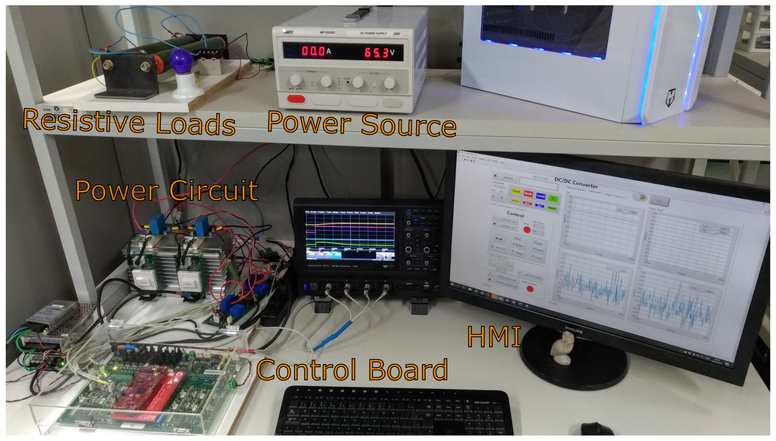
Table 1. A photo of the experimental setup is presented in
Figure 2.
The switches are IGBTs with anti-parallel diodes (SKM150GB12T4). The gate drivers are of the model SKHI 21A. The measured variables by four Hall effect sensors are the input and output voltages (LEM LV 20-P) and the inductor and output currents (LEM LA 55-P).
To allow a greater range of tests, the Texas Instruments DSP TMS320F28379D was used. The DSP works with 200 MHz, 2 cores and a 32 bits floating processing unit. These aspects significantly improve the performance, that imply in a minor delay between measurement and control actions. One of the cores is dedicated for the control routines. Through software interruption, the control routine was executed at the frequency of kHz, which is the maximum frequency of the gates. This is equivalent to a PWM signal of 20 kHz, used in the PI implementation.
For the control routine, the four control techniques presented in
Section 3 have been designed. The classic PI controller (
30) was determined in the continuous-time domain, considering the transfer function
evaluated for a reference voltage of
V, and by means of a methodology based on frequency response, respecting a phase margin of 60°. The obtained PI parameters were
Afterward, it has been discretized using the Tustin method to be executed at 20 kHz.
For the min-type switching strategies, the control design is based on the determination of the Lyapunov matrix
using the conditions previously presented. More specifically, for
and solving the convex optimization problem (
9) subject to (
10), we have obtained a guaranteed cost of
corresponding to
used to implement the non-sampled switching function (
8), identified as Quadratic Non-Sampled (QNS) Controller. For the other control strategies, we have considered a set of equilibrium points
composed of the ones with output voltages varying from 5 V to 120 V with steps of 5 V. The same has been adopted for obtaining the set
. Hence, solving the convex optimization problem (
16) subject to (
17) we have obtained
and
important for the switching function (
14) identified as Robust Non-Sampled (RNS) Controller. For the sampled switching function, we have discretized the system with a sampling period of
s and solved the conditions of Theorem 2 for
and
containing the desired equilibrium points. We have obtained
and
which, together with
h provided in (
27), allows us to implement the switching function (
26) denoted as Robust Sampled (RS) Controller. Notice that, for the adopted sampling period
, since
s is sufficiently small. For this reason, we have adopted only
for all switching functions, which has eased considerably its practical implementation. In the next section, we present important properties of these controllers concerning the switching frequency variation.
4.1. Frequency Variation
In this subsection, our goal is to analyze the switching frequency variation of a Buck–Boost converter operating under min-type switching control strategies. Although they have been widely adopted in the literature, to the best of authors’ knowledge, a study about switching frequency variation as a means of reducing the power consumption has never been made. For this purpose, for each control technique, we have obtained this frequency profile as a function of the output voltage, taking into account its value when the system attains the steady-state.
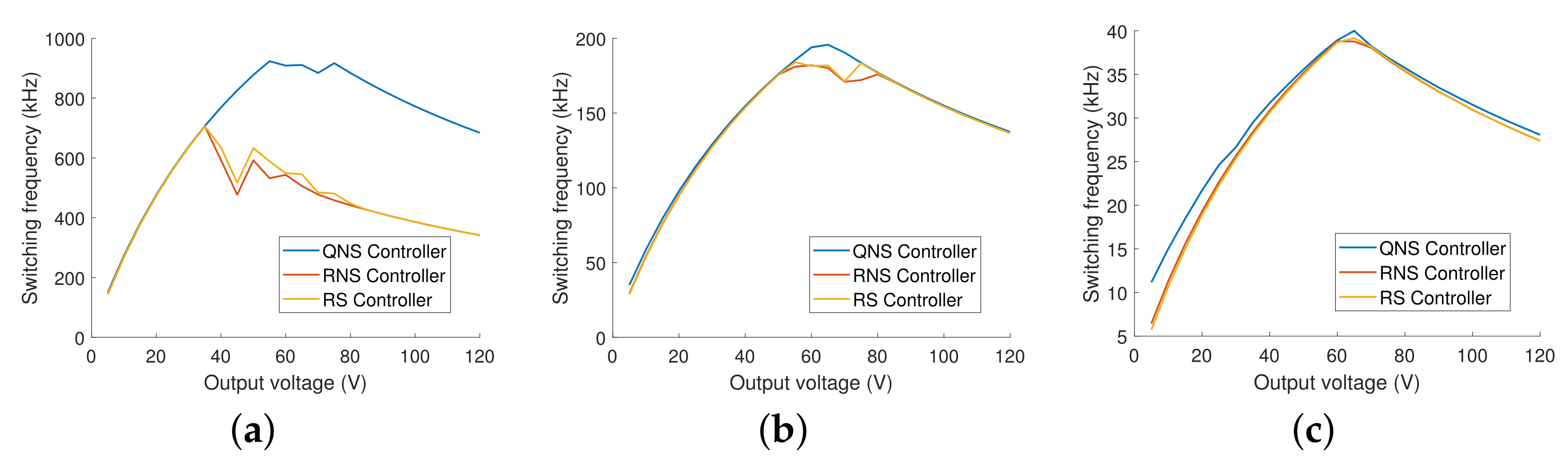
Through simulation, we have obtained these profiles for control frequencies of 1 MHz, 200 kHz, and 40 kHz, ignoring the existence of dead-time. The plots for each control technique are presented in
Figure 3.
It is important to mention that the PI controller always operates with a switching frequency equal to the control one. Differently, in the min-type strategies, this frequency depends considerably on the output voltage and switches less frequently for low and high voltage values. This may lead to a power loss reduction without any additional algorithm.
The triangular pattern observed in these plots indicates that the frequency not necessarily increases with the output voltage, but its peak may have some relationship with the supply voltage. Moreover, as observed in the plot for 40 kHz, with the control frequency reduction, all the rules converge to the same curve and, therefore, become similar in terms of switching losses.
Another notable aspect of the switching strategies is that the steady-state error increases with the reduction in the control frequency. For each min-type strategy, we have determined the mean of the errors obtained for all range of output voltages, obtaining the values presented in
Table 2. Notice that, in most cases, the error is relatively small, being significant only for the QNS controller, which has attained a maximum value of approximately
V in the tested range. In the next section, we present a correction method, which makes it possible to operate the converter with zero-error.
4.2. Steady-State Correction
As it has been observed during the simulation and other studies, such as [
4], the use of min-type control strategies for limited switching frequency, generally, results in a steady-state error, which may even reach considerable values when the operating conditions are not compatible with the control design ones. The magnitude of this error depends on the switching frequency and the model precision, but it is usually noticeable whenever the converter operates with a load different from the one considered during the control design. As load variation is common and expected for most applications, it is interesting to be able to achieve zero-error operation, regardless of any model imperfection.
To treat this problem, some techniques have been already proposed. In [
4], a controller is used to adjust the equilibrium point voltage and the new corresponding coil current is calculated accordingly. In [
7], a low-pass filter is used to estimate the equilibrium current. In [
8], two methods of acquiring the equilibrium point with partial information are approached. The first consists in the use of a low-pass filter, similar to the one applied in [
7]. The other method relies on the use of an integrator to correct the error from a current estimation obtained from the averaged model.
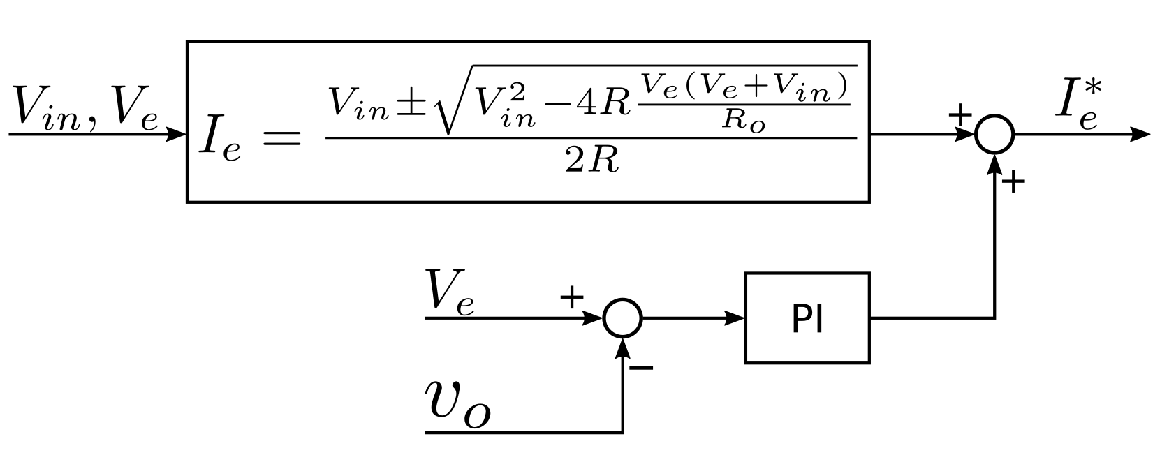
The method proposed here adapts the technique from [
8]. The problem of using an integrator to correct the coil current value is that, if it is designed to present a quick response, an abrupt reference or load change may result in a noticeable voltage error and oscillation, which might be a problem for some applications. To mitigate this risk, the integrator has been replaced by a PI controller, making it possible for the system to have a quick response while avoiding oscillations.
Figure 4 presents the adopted configuration.
With this method, the zero-error operation can be achieved despite differences between the mathematical model and the real system. As the use of such a methodology can have a significant impact on the transient response, it has been engaged only after the system reaches its steady-state. In the present case, we have used only one PI controller for all the studied control techniques, its parameters are
For the sampled switching function (
26), the estimated current
has not been used to update
h, because this parameter needs a precise correspondence of the pair
and the correction of
has not been considered in the present correction methodology.
5. Experimental Results
For the results presented in
Section 4.1, gate drivers’ delays were not taken into account. However, with the specification of the components provided in
Table 1, we can consider a dead-time and other nonlinearities, making the simulation more similar to the real operation of the system. The considered dead-time is of 5
s and 3
s to open and close the gates, respectively.
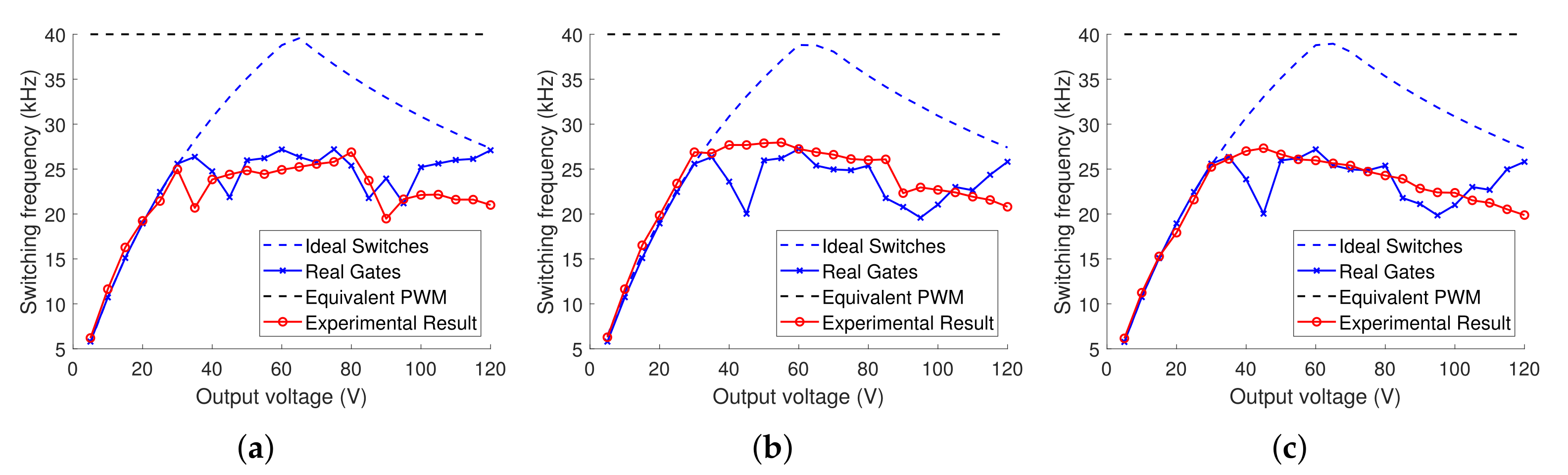
Figure 5 presents switching frequency profiles for the three studied min-type switching strategies, for the ideal and non-ideal cases (with and without dead-times), respectively, obtained by simulation and identified in the figure as Ideal Switches and Real Gates, and the correspondent experimental measures. Each profile has been obtained measuring the switching frequency when the system reaches the steady-state and, consequently, the desired output voltage. It has been considered a control frequency of 40 kHz that is equal to the maximum switching frequency of the gates and adopted the correction method proposed in
Section 4.2 to regulate the steady-state response. In this figure, it is notable a deformation when the simulation results generated by ideal switches and by real gates are compared. This deformation is, however, negligible for output voltages smaller than 25 (V), since they require lower switching frequencies, which smooth the impact of the gate driver delay.
Shifting the focus to the experimental results, it is interesting to observe that the switching frequency was considerably similar to the simulation results. Some differences are noticeable, but not relevant and most likely caused by measurement noises.
The important information about
Figure 5 is that all of the min-switching strategies present a similar frequency profile among them with values much smaller than 40 kHz, which is the maximum frequency of the gate, generally, used by PWM-based control techniques, as it is the case of the classic PI controller. A smaller switching frequency indicates a possible power loss reduction. Notice, however, that if the switches are considered ideal, the value of 40 kHz can be reached for a specific output voltage, but even in this situation, the min-type switching strategies may be more efficient concerning power loss. This occurs because the maximum frequency generally occurs in the steady-state when the system is evolving into a sliding mode. Hence, during the transient response, the frequency is naturally smaller than 40 kHz, while with the PWM it remains constant during all the operation.
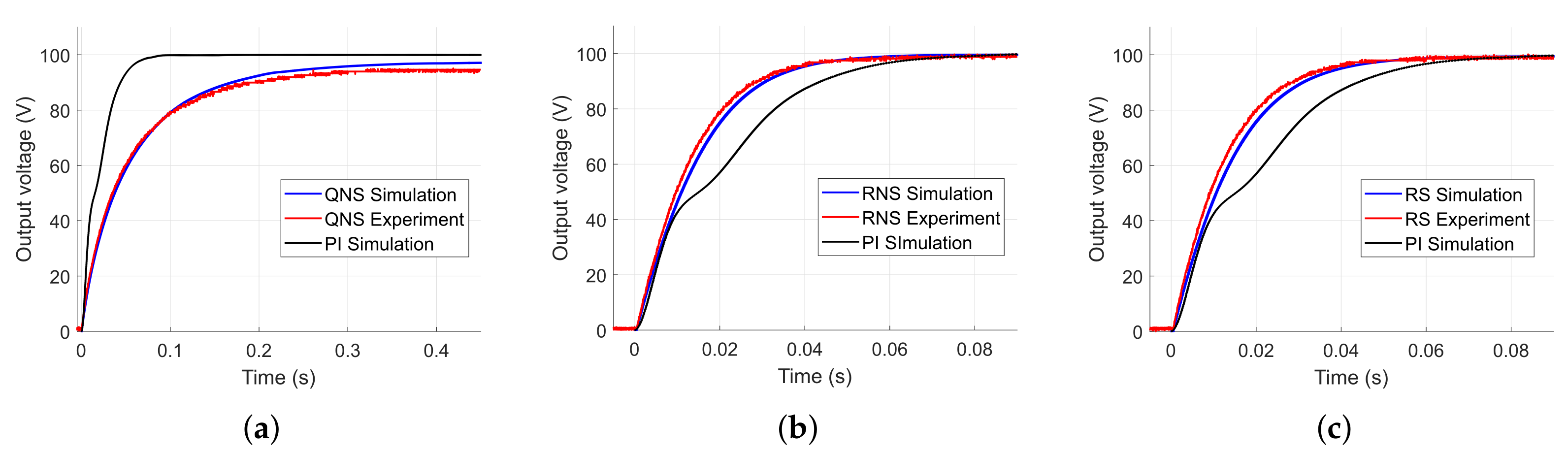
As the frequency analysis indicated the potential of the min-type switching controllers to reduce power loss, it is also interesting to analyze the transient response of the system. With this purpose, the reference voltage is set to follow a step of 100 V.
Figure 6 presents the resulting output voltages for all control strategies, considering simulated and real results. At this first moment, we have not used the correction method for better comparison. Notice that, the responses using the classic PI controller are also provided in the output voltage plots. At first sight, some aspects are interesting to note. The QNS controller experienced the worst performance in both, the transient and the steady-state responses. Indeed, it reached the stability in 218 ms, while the PI controller in 66 ms, and presented a steady-state error of
, which is considerably large. We have observed by simulation that this error reduces by increasing the control frequency, becoming
for 1 MHz.
It is important to remark that, the QNS controller is robust for all possible equilibrium points, while the PI controller was designed to operate specifically for 100 V. On the other hand, the RNS and RS controllers experienced the best performance in the transient response among all, reaching the desired voltage in approximately 50 ms, which is
faster than the PI controller. Moreover, the steady-state error was less than
. Once again, it is important to highlight that, the RNS and RS controllers are robust for a set of equilibrium points
. This indicates that for another reference voltage, the performance of the PI controller can be even worse, while for the RNS and RS controllers, it is maintained approximately similar to the one observed in the
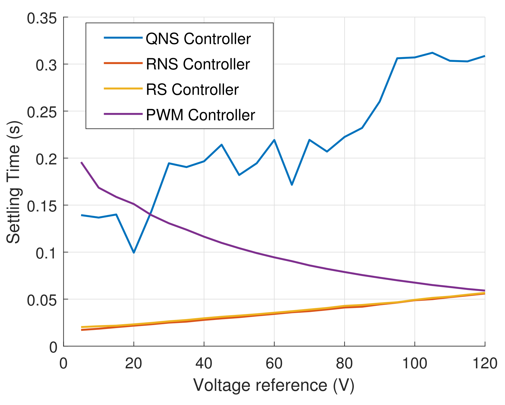
Figure 6. This can be easily verified through simulations. By making multiple reference steps to all of the voltages from
,
Figure 7 demonstrates that the RS and RNS controllers outdo the PI controller in all range of operation. The difference becomes significant in lower voltages, which are farther from the one considered during the design.
Notice that the steady-state error observed in the QNS controller can be corrected by the method proposed in
Section 4.2. In this case, after the converter reaches the desired equilibrium, the correction method can be engaged, assuring the zero-error operation.
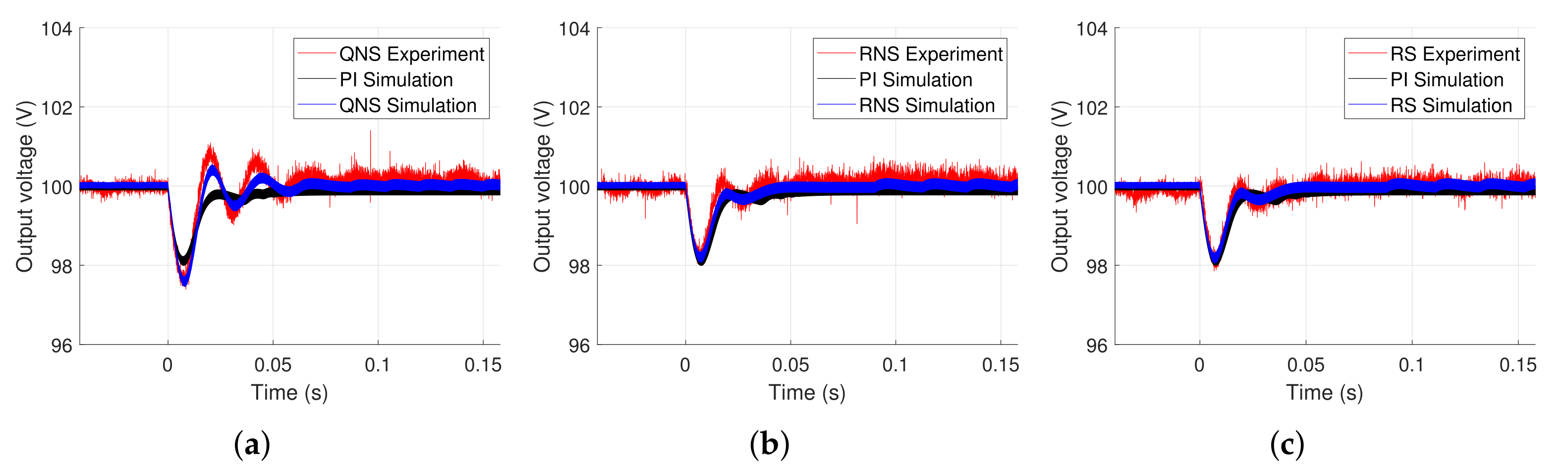
To verify the performance of the min-type switching strategies to load variations, we have added another resistance in parallel with
, with the same value, whose activation is made by a switch after the system reaches the steady-state.
Figure 8 provides the correspondent voltage responses.
It can be noticed that for all min-type switching strategies, the correction method was able to recover the desired voltage after the load change without a great variation on the output voltage. The performance of the control methodologies was similar but with more oscillations in the QNS controller.
6. Conclusions
In this paper, we have demonstrated the application of min-type control strategies to a Buck–Boost converter and compared it with a classic PI controller. We have generalized the available design conditions to make them robust to changes in the equilibrium points without the need for a redesign. The controller performances were evaluated regarding switching frequency variation, response to a reference step, and robustness for load variation. A correction method has also been proposed to approach the known problem of steady-state error and its efficiency was demonstrated through load step tests. Compared to other control techniques, the min-type switching strategies have the following advantages:
They are not designed for averaged systems, as the PWM-based techniques, and explore the nonlinear nature of the switched affine system, being able to provide a better performance in the transient response, as illustrated in
Figure 6 and
Figure 7;
With the generalization proposed in this paper, the RNS and RS switching functions became robust with respect to a set of equilibrium points, without the need for a redesign. This has contributed to guarantee a suitable performance and small steady-state errors when these points are changed during the operation. This robustness property has not been taken into account in [
5,
7];
Differently from the PWM-based techniques, which generally operate in a constant and high switching frequency, in the min-type switching strategies this frequency is variable, generally much smaller than the PWM one, and dependent on the operation point, as illustrated in
Figure 3 and
Figure 5. This certainly leads to a power loss reduction in the electronic switches.
In addition to these advantages, one disadvantage of the these min-type strategies is that they do not have intrinsically the integral action, which is responsible to give robustness with respect to parameter variations. However, to circumvent this problem the correction method provided in
Figure 4 has been proposed and provided suitable performances under load variations as illustrated in
Figure 8. In future studies, the switching strategy may be further developed to include the integral action, mitigating the need for a correction method.


