1. Introduction
Multi-level inverters with current-tracking are widely used in the photovoltaic grid-connected, active filtering and reactive power compensation of medium and high voltage power systems [
1]. With the development of solar cell technology and the reduction in its cost, the multi-level inverter structure with multiple independent DC power supply gradually highlights the characteristics of strong economy, and the increase in the number of levels is conducive to improve the output voltage level of the inverter [
2], in line with the current more popular “silicon into copper retreat” design concept.
Due to the number of power-switching devices in multi-level inverters being large, the probability of faulting is also much greater [
3]. Once a fault occurs, it has a great impact on the power grid and the load. The fault-tolerant control methods of multi-level inverter can be divided into the hardware method and software method. The hardware method usually needs to add spare units or other auxiliary modules in the multi-level inverter topology to obtain fault-tolerant control [
4,
5,
6,
7,
8]. Yang [
8] proposed a fault-tolerant way to add backup switches. The structure can be flexibly reorganized according to different fault modes to achieve fault tolerance. However, it needs the standby switch switching work.
The software method does not need to change the topology of the multi-level inverter, but obtains fault-tolerant control through the control algorithm; it can save hardware costs and simplify the system structure. It mainly includes the following three kinds.
The first way is to shield the faulty unit and reduce the capacity to run. This method is suitable for cascaded inverter [
9]. In order to ensure the symmetry of the three-phase output voltage, in addition to short-circuiting the faulty unit, the non-faulty unit corresponding to the faulty unit in the other two phases is usually also shielded [
10]. Therefore, some non-faulty units are not fully utilized, and there is a waste of hardware resources. Taking the seven-level cascaded inverter as an example (Mehta [
11]), the output line voltage amplitude of the inverter’s derating operation is proven, with the output current being reduced to half of what is considered normal.
The second way is the neutral point offset method, whose essence is to inject a basic zero-sequence voltage [
12,
13]. The maximum symmetrical line voltage can be obtained by this method when only the faulty unit is bypassed, but the neutral point offset method can easily cause low-order voltage harmonics to rise. Zhang [
14] proposed a differential compensation modulation scheme, which can not only perform the fault-tolerant operation, but also reduce the voltage harmonics caused by neutral point offset. However, when the load power factor is low, the injected zero-sequence voltage may cause the actual power to backflow, causing the DC side voltage to rise, even beyond the set range.
The third way is to adjust the DC side voltage value of the inverter. Song [
15], by increasing the DC side voltage of the cascaded unit of the fault phase, concluded that the maximum output voltage of this phase is the same as that before the fault. According to Yousef [
16], the DC side voltage of the faulty phase of the inverter is increased to 2
N/(2
N − 1) times of the original voltage, which can perform the fault-tolerant operation and selectively eliminate low-order voltage harmonics. However, this kind of fault-tolerant method is only suitable when the DC voltage is controllable, in which case it will increase the voltage stress of power electronic devices. For this reason, Laxman [
17] and Mohsen [
18] proposed a fault-tolerant control method that combines neutral point offset and DC side voltage adjustment, which can reduce the voltage stress of power electronic devices under fault conditions. In this kind of methods, the increase in the DC side voltage of the inverter will cause the change of the spatial position of the voltage vector, which makes the selection algorithm of the voltage vector more complex.
In summary, a hysteresis SVPWM reconfigurable fault-tolerant control method for single-phase voltage source multilevel inverter with current-tracking is proposed in this paper. This method combines the advantages of hardware and software fault-tolerant control methods. When power single-switch and double-switch faults occur, the method of topology reconstruction and redundant voltage vector equivalent replacement is used to achieve fault-tolerant control. The redundant voltage vector with the coincident position is preferentially selected for equivalent replacement. If there is no coincident vector, the other vectors with the closest position and effect are selected to achieve fault-tolerant control.
The study is structured as follows. After the introduction, a new topology and hysteresis control method are proposed in
Section 2. Then, most cases of failure status are discussed in
Section 3, followed by the analysis of the hysteresis SVPWM reconfigurable fault-tolerant control method in
Section 4. Finally, the correctness and effectiveness of the method are proved by analyzing the experimental results.
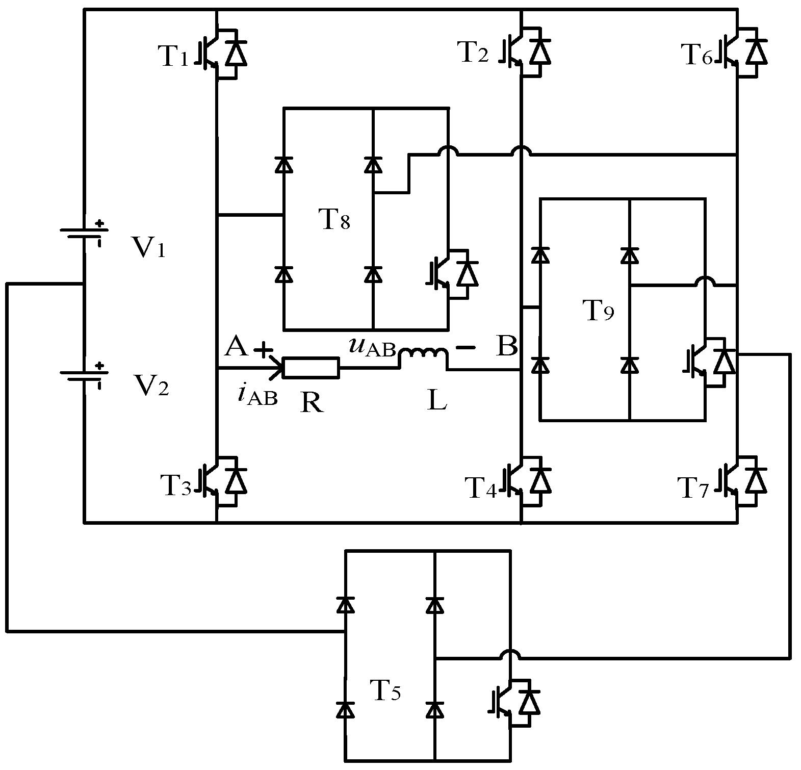
2. New Type of Single-Phase Voltage Source Multilevel Inverter
Figure 1 is a single-phase seven-level voltage source inverter composed of two independent DC power supplies and nine power switching devices. Each switch is connected in series with a quick fuse, so that the short-circuit fault can be regarded as an open-circuit fault for the analysis. The independent DC power supply is V
1 = 2V
2 = 2
E. Among them, the T
5, T
8 and T
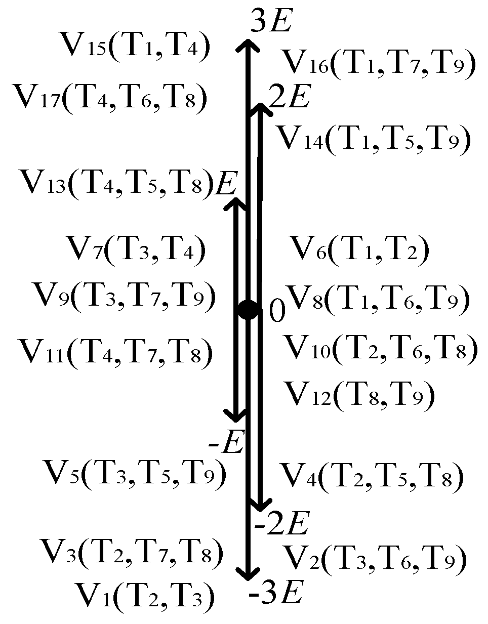
9 3 switching devices can use the common single-phase bridge uncontrollable rectifier module, and the IGBT is placed on the DC side of the rectifier bridge. The switching state and voltage space vector of the inverter are shown in
Table 1. The spatial position of the voltage vector is shown in
Figure 2. The inverter has 17 switching states and voltage space vectors, which can output seven levels of 3
E, 2
E,
E, 0, −
E, −2
E, ande −3
E. Under the fault state, the redundant voltage vector can be generated through the reconstruction of the topology, which lays the foundation for the fault-tolerant control algorithm.
In order to simplify the algorithm, this paper selected V1, V4, V5, V6, V13, V14 and V15 to generate seven levels of −3E, −2E, −E, 0, E, 2E, and 3E under the non-fault state, that is, only one inverter switching state is reserved for each level. In this case, the switching devices T6 and T7 only participate in the work during fault-tolerant control.
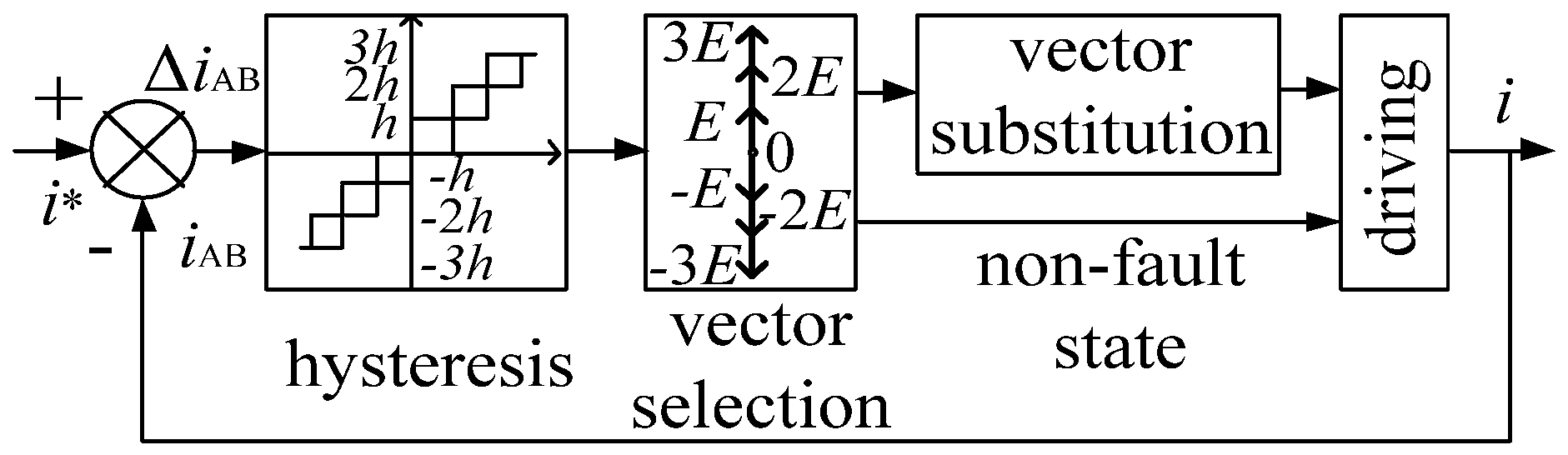
As shown in
Figure 3 and Formula (1), firstly, the current tracking error Δ
iAB =
i* −
iAB was determined by hysteresis comparison. Additionally, then the tracking error was reduced to within the hysteresis range by selecting the inverter voltage vector reasonably, where
i* is the reference current and
iAB is the actual current. The width of the third order hysteresis loop is
h, 2
h and 3
h, respectively. The voltage vector selection method in the non-fault state is shown in
Table 2. In the fault state, the voltage vector selected by the original algorithm needs to be equivalently replaced, that is, fault-tolerant control is performed.
3. Failure Status Analysis
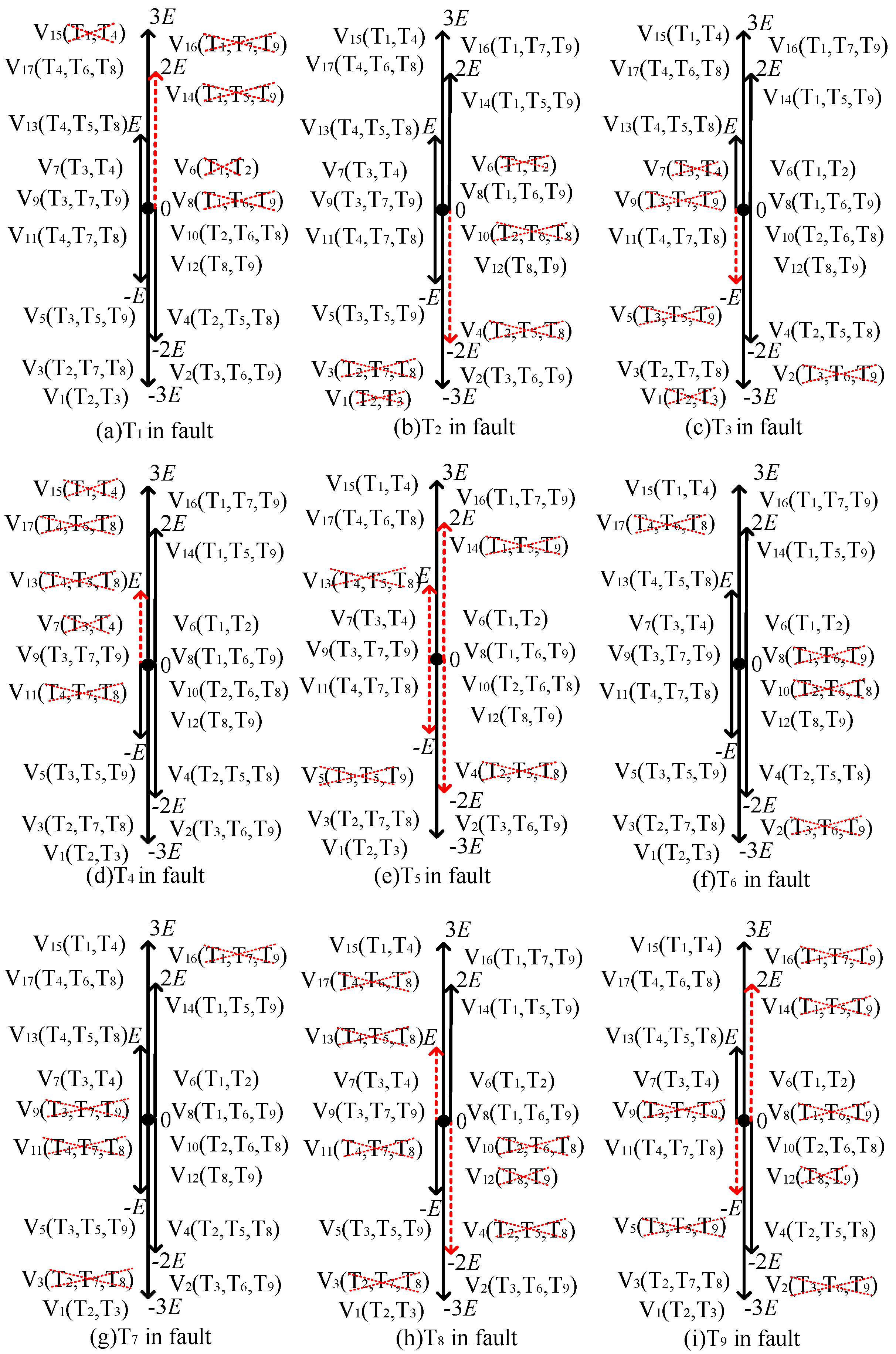
When an open-circuit fault occurs in one or several IGBTs of the inverter, some voltage vectors will be affected by the fault and become fault vectors. This is shown in
Table 3, where “√” indicates that the fault has no effect on the voltage vector and “×” indicates that it has an effect on the voltage vector, that is, the voltage vector becomes the fault vector.
It can be seen from
Table 3 that, when an open-circuit fault occurs in one of T
1~T
9, the inverter can output at least one positive level, zero level and negative level, that is, theoretically, it is still possible to control the increase and decrease in the load current, but the choice of voltage vectors and the number of output levels are reduced.
Figure 4 show the space distribution diagram of the inverter voltage vector under the single-switch open-circuit fault. Among them, the red dotted line represents the fault vector, which needs to be replaced by the voltage vector. The black solid line represents the non-fault vector and does not need to be replaced by the voltage vector.
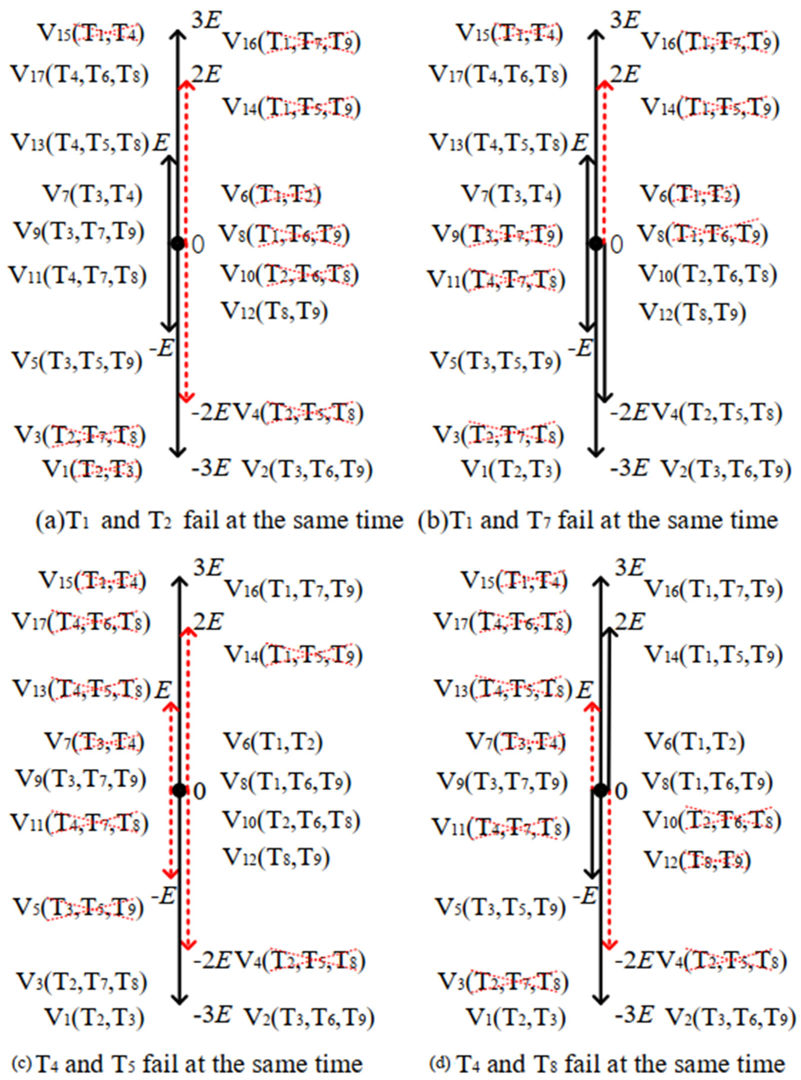
Figure 5 uses the T
1 and T
2, T
1 and T
7, T
4 and T
5, and T
4 and T
8 faults as examples to analyze the double-switch open-circuit fault. In the same way, other double-switch failures can be obtained, which will not be repeated in this paper. In addition, the probability of failure of more than three switching devices at the same time is relatively small, which will not be discussed in this paper.
4. Hysteresis SVPWM Reconfigurable Fault-Tolerant Control Method
As shown in
Figure 2 and
Table 3, when the voltage vector selected by the original algorithm before the fault occurs is a non-fault vector, the voltage vector is the final output vector of the inverter; when the selected voltage vector is a fault vector, voltage vector replacement is required.
Table 4 and
Table 5 show the voltage vector alternative methods for inverter single-switch open-circuit and double-switch open-circuit faults; among them, there are 9 types of single-switch open-circuit faults and 36 types of double-switch open-circuit faults; “√” means that the fault has no effect on the voltage vector and does not need to be replaced.
Taking the T1 single-switch open-circuit fault as an example, the inverter can only output the four levels E, −E, −2E, and −3E in the fault-tolerant operation state, and the number of output levels changes from seven under the normal state to four kinds. The seven voltage vectors V1, V4, V5, V6, V13, V14 and V15 are selected by the original algorithm. V1, V4, V5 and V13 are not affected by this fault and can be used continuously without replacement; V6, V14 and V15 are affected by the fault and need to be replaced. Among them, V6 and V15 can be replaced by the voltage vectors V7 and V17, respectively, and the inverter output levels before and after the replacement are the same. For V14, there is no voltage vector with the same level value that can be chosen. In order to simplify the algorithm, the vector V13 or V17 with the same level direction and similar position to replace it is selected. In other words, when h < ΔI ≤ 2 h and 2 h < ΔI ≤3 h, the vector V13 is select, or when 2h < ΔI ≤ 3 h and ΔI > 3 h, vector V17 is select.
Taking the voltage vector selection for T
1 single-switch fault tolerance as an example, according to
Table 3, the final output voltage vector replaced is shown in Formula (2). In the same way, the voltage vector selection for other single-switch fault tolerances can be obtained, which are shown in
Table 4.
When a double-switch open-circuit fault occurs in the inverter, there are 36 double-switch fault permutations and combinations for 9 IGBTs. The analysis shows that the inverter can output at least one positive level, zero level and negative level under 30 kinds of double-switch faults, and the fault-tolerant control can be performed through voltage vector substitution. Taking the T
1 and T
2 double-switch open circuit failures as examples, the final output voltage vector after being replaced is shown in Formula (3). In the same way, the voltage vector selection for other double-switch fault tolerances can be obtained, which are shown in
Table 5.
In addition, when T1 and T4, T1 and T8, and T4 and T9 fail at the same time, the inverter output lacks the positive level. When T2 and T3, T2 and T9, and T3 and T8 fail at the same time, the inverter output lacks the negative level. None of the above six cases can achieve fault-tolerant control through inverter topology reconstruction and voltage vector substitution.
In this way, based on
Table 4 and
Table 5, the effective voltage vectors are reasonably selected according to the current tracking error to control the rise and fall of the actual output current of the inverter, so as to track the reference current and achieve fault-tolerant control.
Currently, the commonly used fault-tolerant control methods for multilevel inverters usually require the switching operations of the main and spare switching devices of the inverter. Taking the common fault-tolerant control of a cascaded multilevel inverter as an example, when a fault occurs, it is usually necessary to cut off the faulty cascade unit, and introduce a spare cascade unit to replace the faulty unit. In the process of the fault-tolerant control of this paper, the main circuit topology of the inverter never changes and the switching operation of the main and spare switching devices is not required. The switching of the variable structure unit is completed directly by the drive signal. Therefore, there is no need to add additional switching devices required for switching the main and spare units. The operation is simple and the stability is high.
5. Simulation and Experiment
5.1. Simulation Analysis
In order to verify the correctness and effectiveness of the proposed method, a simulation analysis based on the MATLAB Simulink environment was conducted. The system parameters were as follows: the two power supply voltages on the DC side of the inverter were 24 V and 12 V. The output reactor was 5 mH, and the resistance was 5 Ω. The reference current was a sine wave with an amplitude of 4 A, and the hysteresis width h of each order was 0.1.
Figure 6 shows the waveforms of the single-switch open-circuit fault and double-switch open-circuit fault. Before 0.04 s, the inverter works normally; failure was applied at 0.04 s and a fault-tolerant operation at 0.06 s. Taking the T
1 single-switch open-circuit fault as an example, before 0.04 s, the inverter output seven levels and a stable current. After the fault was applied, the inverter output level lacked the 3
E, 2
E, and 0 levels. Additionally, the three levels of −
E, −2
E, and −3
E in the negative half axis were not affected. Therefore, the output current waveform of the positive half-axis had evident irregular changes, while the negative half-axis waveform was almost unaffected. After 0.08 s, the inverter output level number rose to 6 levels and the output current waveform returned to normal, and the sine wave was good.
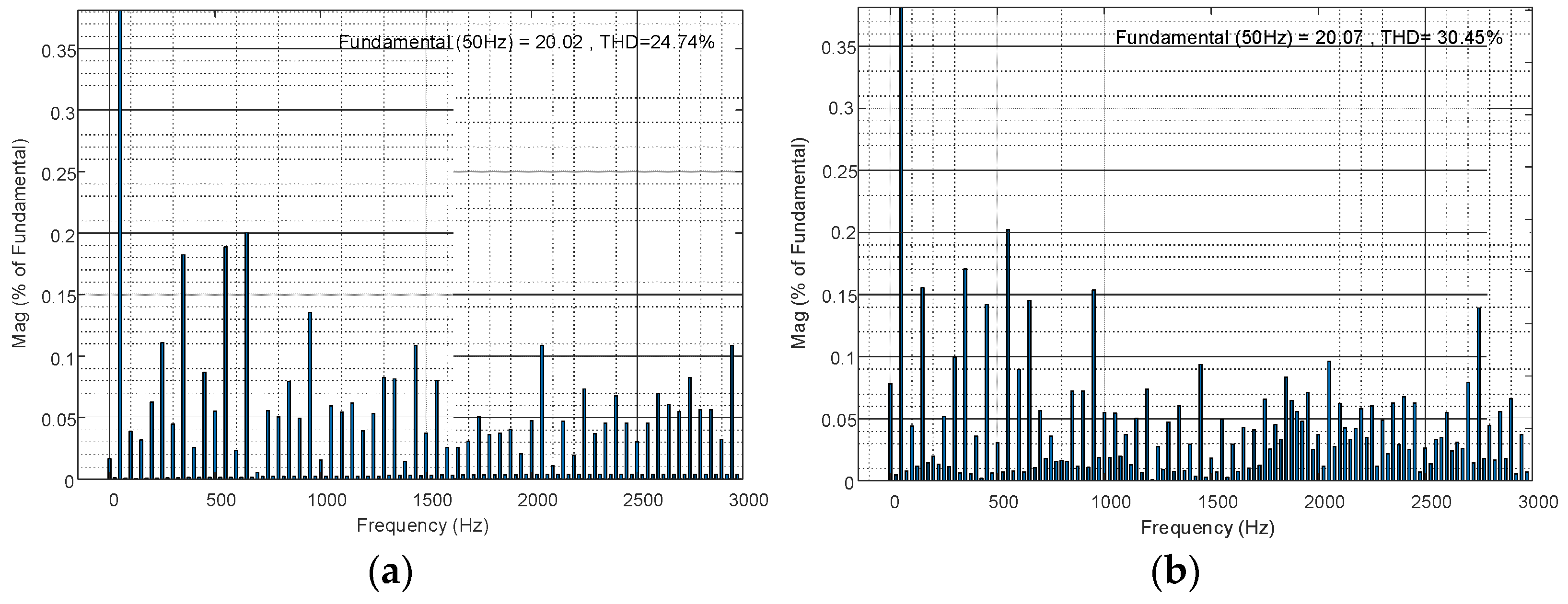
Figure 7 shows the total harmonic distortion for the output voltage when all switches are normal and at the T
1 fault. Other types of failure analysis are the same and will not be repeated in this paper.
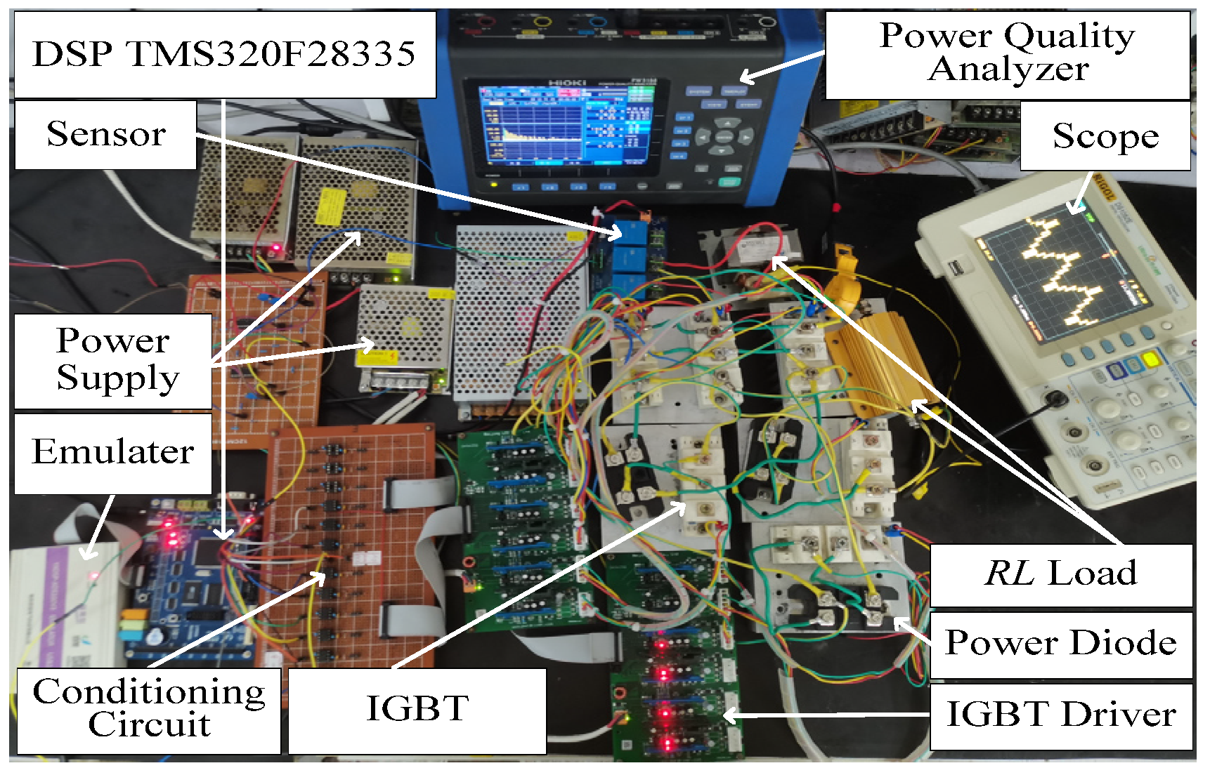
5.2. Experimental Analysis
Figure 8 shows the experimental prototype. It was basically consistent with the simulation parameters. The IGBT model of the inverter power switching device was a BSM50GB120DN2, and the power diode adopted was the single-phase rectifier bridge MDQ60-1600V. The driving circuit used was a Luomuyuan integrated IGBT driver module DA962D6, and the system main control chip used a 32-bit DSP TMS320F28335. The oscilloscope model used in the experiment was DS1052E, and the power quality analyzer used was HIOKI PW3198.
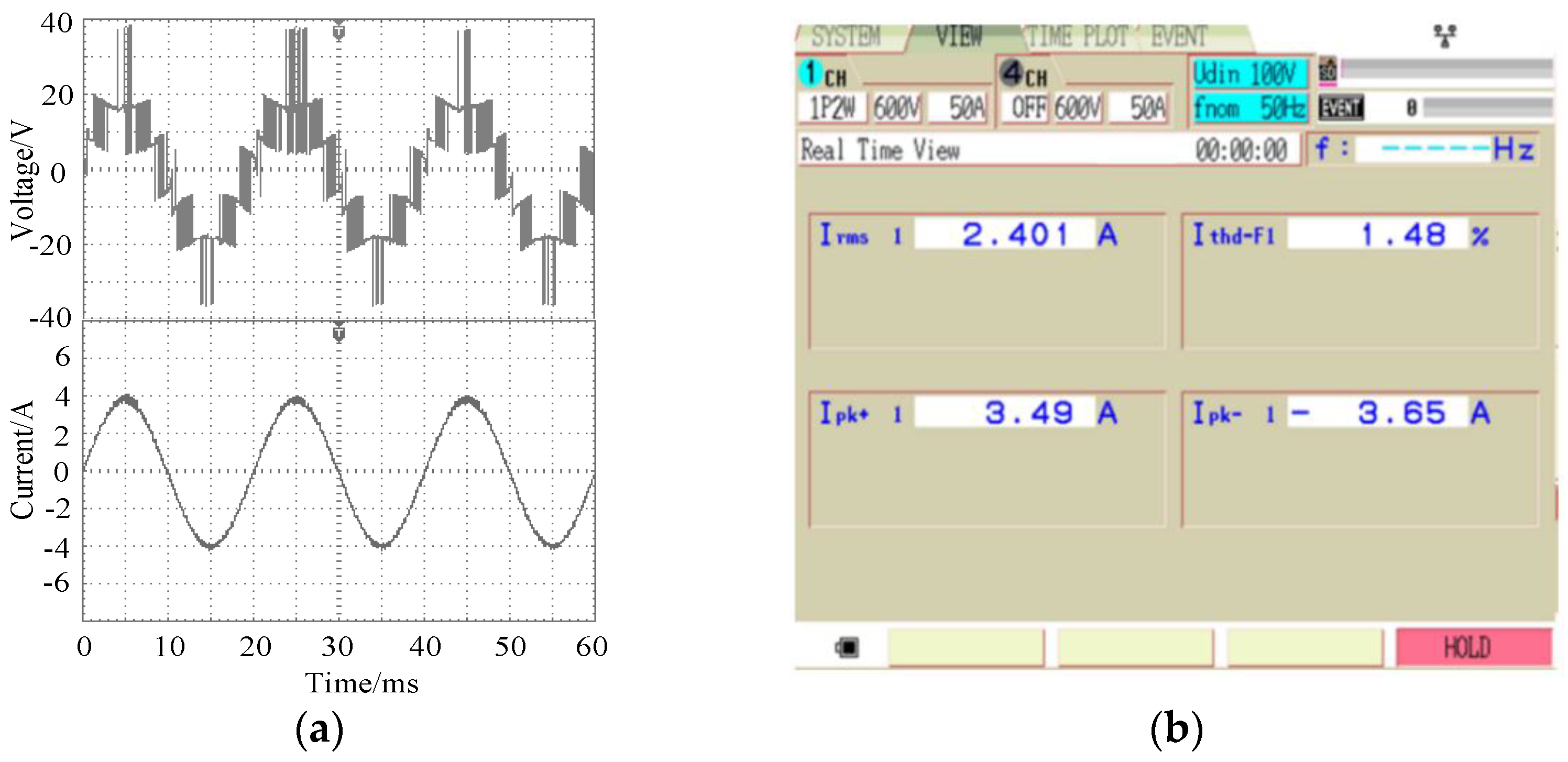
In the non-fault state, the inverter output voltage and current waveforms and the corresponding current THD diagram are shown in
Figure 9. It can be seen from the figure that, when all switching devices were normal, the inverter output voltage and current waveforms changed according to the sinusoidal law. The output voltage in this case had 7 levels, and the output current accurately tracked the reference value. The current harmonic distortion rate was 1.48%.
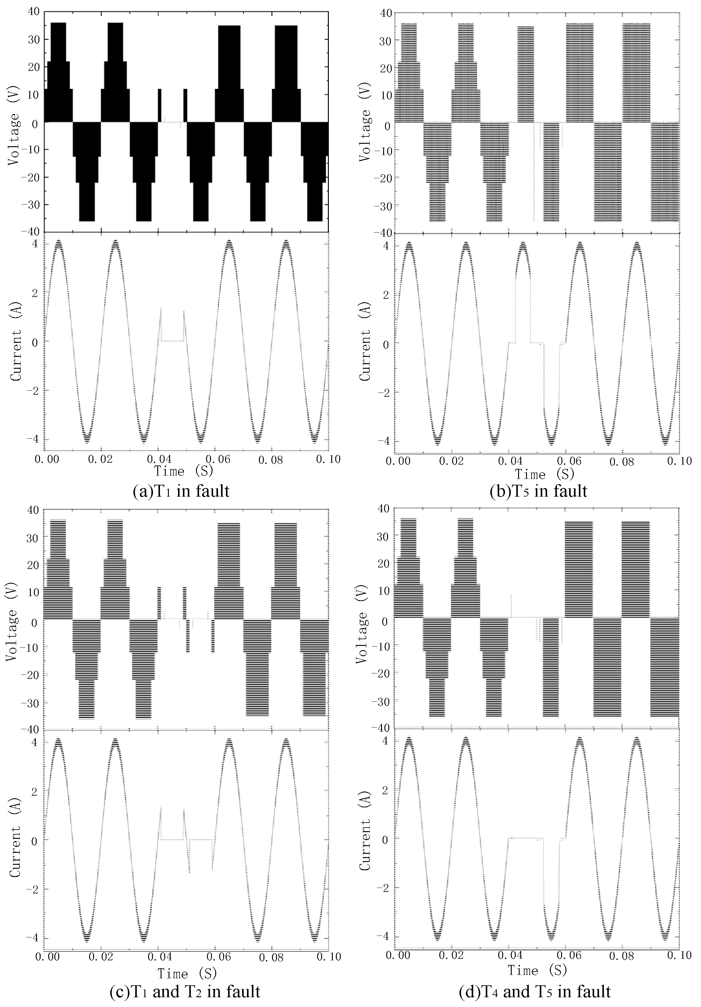
5.2.1. Single-Switch Open-Circuit Fault Analysis
We disconnected T1~T9 in the inverter one by one to simulate the state of each IGBT when the open-circuit fault occurs. Due to many failures, single-switch failures only took T1 failures as an example.
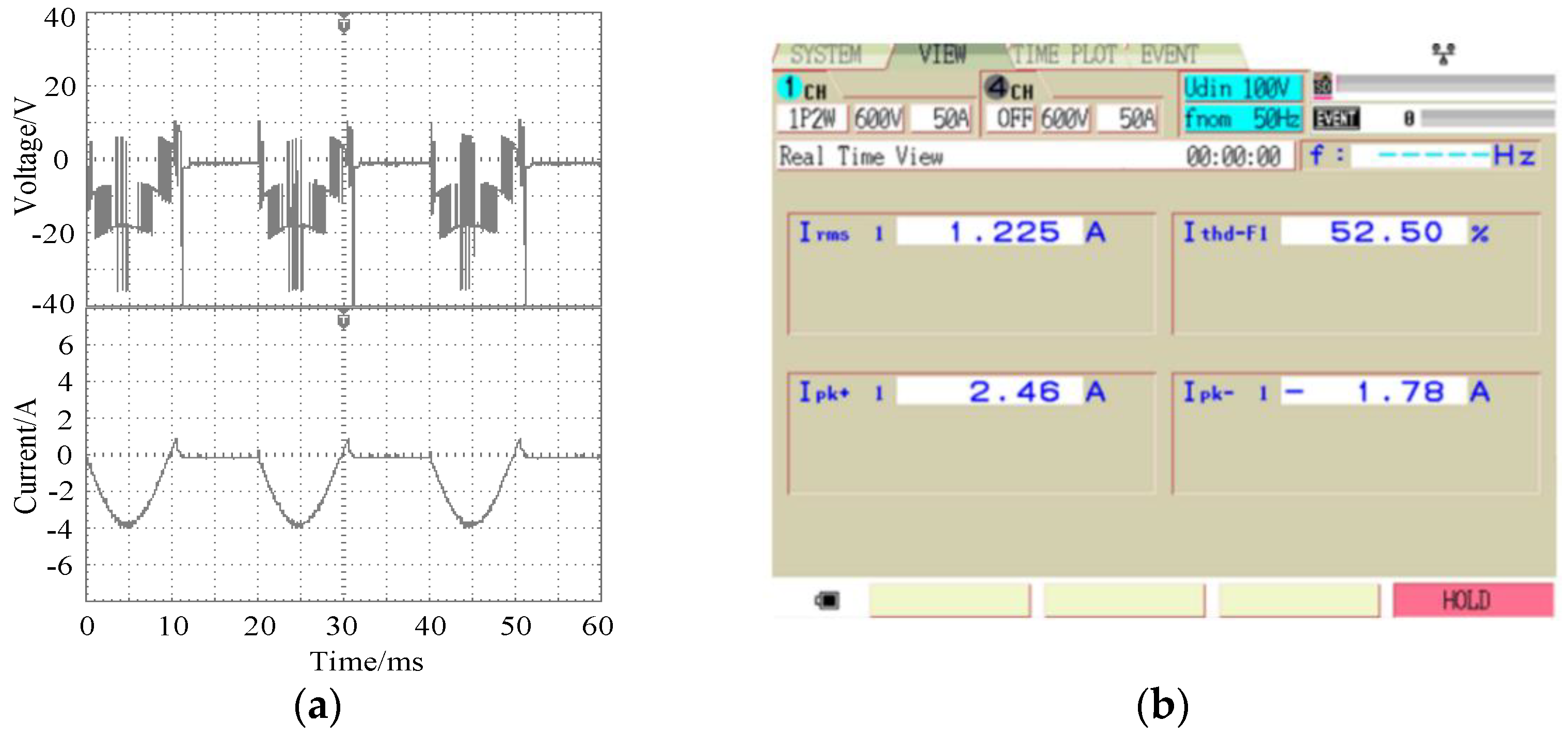
From
Figure 10, it can be seen that, when an open-circuit fault occurred in T
1, the number of output levels changed to 4 kinds. Therefore, the output current waveform had evident irregular changes. In this case, the current distortion rate was as high as 52.5%.
From the T
1 fault-tolerant operation waveform in
Figure 11, it can be observed that the inverter output level number rose to six levels after the redundant voltage vector was replaced. The output current waveform returned to normal, and the sine was good. The harmonic distortion rate of the current under fault-tolerant operation was 1.53%, which is slightly higher than that in the non-fault state.
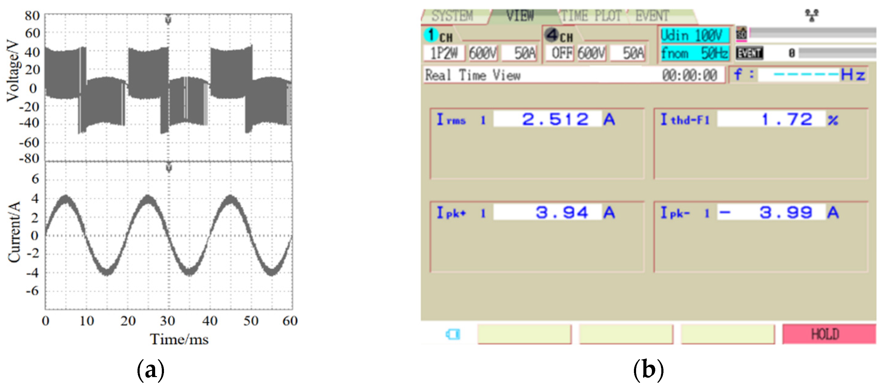
Similarly, the situation of T
5 fault tolerance was obtained and is shown in
Figure 12. In this case, the harmonic distortion rate of the output current was 1.72%. Other single-switch open circuit faults are not repeated in this paper.
From the above analysis, it can be concluded that the inverter output current accurately tracks the reference current by using the fault-tolerant control method based on voltage vector substitution when the single switch has an open-circuit fault. The total harmonic distortion rate of the current was higher than before the fault. The increase in current tracking error was caused by the inverter output level error during the voltage vector substitution process.
5.2.2. Double-Switch Open-Circuit Fault Analysis
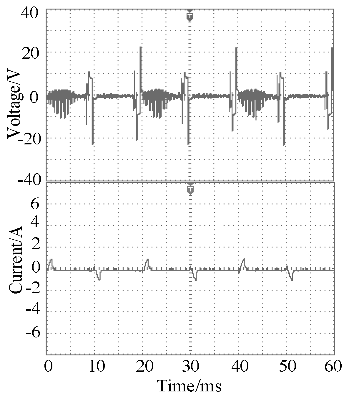
The double-switch fault takes the case of the T
1 and T
2 faults occurring at the same time as an example, and the fault waveform is shown in
Figure 13.
When T1 and T2 fail at the same time, the number of output levels of the inverter was reduced from 7 to 2 types. Because most of the output levels were lost, the inverter could not track the reference current normally. The output voltage and current also had evident irregular changes.
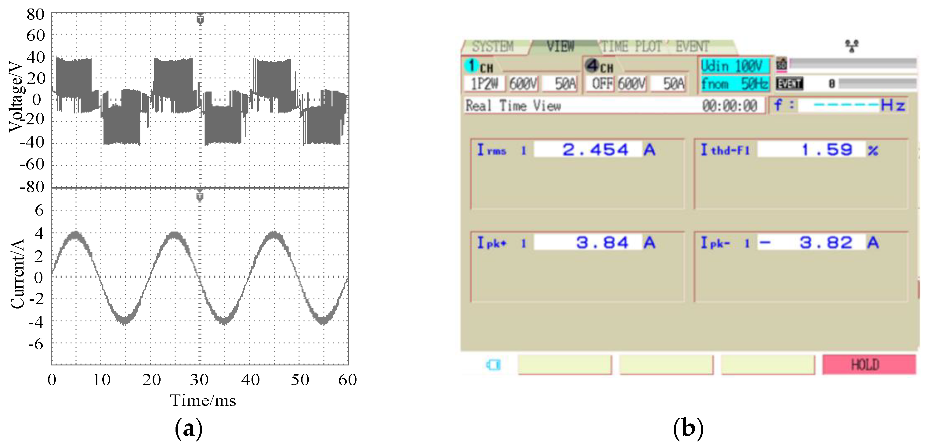
The output voltage, current and distortion rate of the inverter after the fault-tolerant control of the double-switch fault are shown in
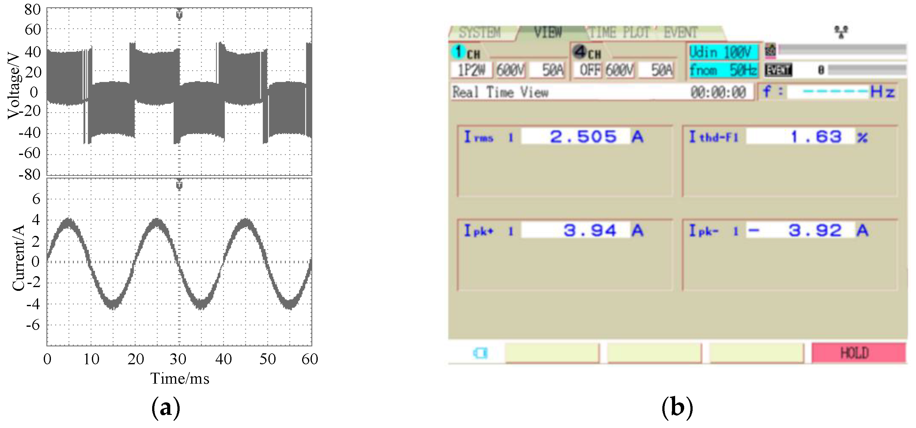
Figure 14. It can be seen from the figure that, after the fault-tolerant control, the output current of the inverter returned to normal. The sine was better, and the harmonic distortion rate of the current was 1.59%. Similarly,
Figure 15 shows the fault-tolerant waveform when the T
4 and T
5 double-switch have open-circuit faults at the same time. In this case, the sine of the output current was better, and the current harmonic distortion rate was 1.63%.
Above all, the fault-tolerant control method can ensure that the inverter output current tracks the reference current more accurately when the double-switch open-circuit fault occurs at the same time. The current harmonic distortion rate is slightly higher than before the fault.
In summary, when the inverter has a single-switch or double-switch open-circuit fault, the fault-tolerant control method can ensure that the inverter tracks the reference current more accurately, that is, to ensure the system continues to operate stably.
6. Conclusions
A method of hysteresis SVPWM reconfigurable fault-tolerant control for single-phase voltage source multilevel inverter with current tracking is proposed. It not only has the characteristics of the rapid response of hysteresis control, but also retains the advantages of the high efficiency of SVPWM. Based on the reconstruction of the inverter topology, fault-tolerant control was achieved by using redundant voltage vector substitution. The experimental results prove that this method can ensure the continuous operation of the inverter under the condition of single-switch and most double-switch open-circuit faults, and can accurately track the reference current value. In this method, the inverter is directly controlled by driving the signal to carry out variable structure operations; it does not require switching the operations of the main and spare switching device units of the inverter. It can save additional switching devices required in the switching process and has the advantages of having a simple operation and high stability.
Author Contributions
Conceptualization, G.L. and L.W.; methodology, G.L. and L.W.; software, L.W.; validation, G.L., L.W. and F.L.; formal analysis, L.W.; investigation, F.L.; resources, F.L.; data curation, L.W.; writing—original draft preparation, G.L. and L.W.; writing—review and editing, L.W.; visualization, F.L.; supervision, G.L.; project administration, G.L.; funding acquisition, G.L. All authors have read and agreed to the published version of the manuscript.
Funding
National Natural Science Foundation of China (51307076) and Doctoral Research Startup Fund Project in Science and Technology Department of Liaoning Province, China (202101273).
Institutional Review Board Statement
Not applicable.
Informed Consent Statement
Not applicable.
Data Availability Statement
Not applicable.
Conflicts of Interest
The authors declare no conflict of interest.
References
- Sajadi, R.; Iman-Eini, H.; Bakhshizadeh, M.K.; Neyshabouri, Y.; Farhangi, S. Selective Harmonic Elimination Technique with Control of Capacitive DC-Link Voltages in an Asymmetric Cascaded H-Bridge Inverter for STATCOM Application. IEEE Trans. Ind. Electron. 2018, 65, 8788–8796. [Google Scholar] [CrossRef] [Green Version]
- Vahedi, H.; Sharifzadeh, M.; Al-Haddad, K. Modified Seven-Level Pack U-Cell Inverter for Photovoltaic Applications. IEEE J. Emerg. Sel. Top. Power Electron. 2018, 6, 1508–1516. [Google Scholar] [CrossRef]
- Selvaraj, R.; Desingu, K.; Chelliah, T.R.; Khare, D.; Bharatiraja, C. Fault Tolerant Operation of Parallel-Connected 3L-Neutral-Point Clamped Back-to-Back Converters Serving to Large Hydro-Generating Units. IEEE Trans. Ind. Appl. 2018, 54, 5429–5443. [Google Scholar] [CrossRef]
- Mirafzal, B. Survey of fault-tolerance techniques for three-phase voltage source inverters. IEEE Trans. Ind. Electron. 2014, 61, 5192–5202. [Google Scholar] [CrossRef]
- Agarwal, S.; Kapoor, A.K. Full-Fault-Tolerant Single-Phase 13-Level Cascaded Multilevel Inverter with Modified H-Bridge Modules. In Proceedings of the 2018 International Conference on Computing, Power and Communication Technologies (GUCON), New Delhi, India, 28–29 September 2018; pp. 941–945. [Google Scholar]
- Salimian, H.; Iman-Eini, H. Fault-tolerant operation of three-phase cascaded H-bridge converters using an auxiliary module. IEEE Trans. Ind. Electron. 2016, 64, 1018–1027. [Google Scholar] [CrossRef]
- Jahan, H.K.; Panahandeh, F.; Abapour, M.; Tohidi, S. Reconfigurable multilevel inverter with fault-tolerant ability. IEEE Trans. Power Electron. 2017, 33, 7880–7893. [Google Scholar] [CrossRef]
- Yang, H.; Wang, T.; Tang, Y. A Hybrid Fault-Tolerant Control Strategy for Three-phase Cascaded Multilevel Inverters Based on Half-bridge Recombination Method. In Proceedings of the IECON 2021—47th Annual Conference of the IEEE Industrial Electronics Society, Toronto, ON, Canada, 23 October 2021; pp. 1–6. [Google Scholar]
- Haji-Esmaeili, M.M.; Naseri, M.; Khoun-Jahan, H.; Abapour, M. Fault-tolerant structure for cascaded H-bridge multilevel inverter and reliability evaluation. IET Power Electron. 2017, 10, 59–70. [Google Scholar] [CrossRef]
- Hammond, P.W. Enhancing the reliability of modular medium-voltage drives. IEEE Trans. Ind. Electron. 2002, 49, 948–954. [Google Scholar] [CrossRef]
- Mehta, P.; Sahoo, S.; Kumar, M. A fault-diagnosis and tolerant control technique for five-level cascaded h-bridge inverter. IET Circuits Devices Syst. 2021, 15, 366–376. [Google Scholar] [CrossRef]
- Kim, S.M.; Lee, J.S.; Lee, K.B. A modified level-shifted PWM strategy for fault-tolerant cascaded multilevel inverters with improved power distribution. IEEE Trans. Ind. Electron. 2016, 63, 7264–7274. [Google Scholar] [CrossRef]
- Sun, L.; Wu, Z.; Xiao, F.; Cai, X.; Wang, S. Suppression of real power back flow of nonregenerative cascaded H-bridge inverters operating under faulty conditions. IEEE Trans. Power Electron. 2015, 31, 5161–5175. [Google Scholar]
- Zang, Y.; Lin, J.Q.; Wang, X.; Xu, B. Control Method for Cascaded H-Bridge Inverter with Faulty Cells Based on Differential PWM. Proc. CSEE 2006, 26, 65–69. [Google Scholar]
- Song, W.; Huang, Q.A. Fault-Tolerant Design and Control Strategy for Cascaded H-Bridge Multilevel Converter-Based STATCOM. IEEE Trans. Ind. Electron. 2010, 57, 2700–2708. [Google Scholar] [CrossRef]
- Neyshabouri, Y.; Iman-Eini, H. A new fault-tolerant strategy for a cascaded H-bridge based STATCOM. IEEE Trans. Ind. Electron. 2018, 65, 6436–6445. [Google Scholar] [CrossRef]
- Maharjan, L.; Yamagishi, T.; Akagi, H.; Asakura, J. Fault-tolerant operation of a battery-energy-storage system based on a multilevel cascade PWM converter with star configuration. IEEE Trans. Power Electron. 2010, 25, 2386–2396. [Google Scholar] [CrossRef]
- Aleenejad, M.; Mahmoudi, H.; Ahmadi, R. A fault-tolerant strategy based on fundamental phase-shift compensation for three-phase multilevel converters with quasi-Z-source networks with discontinuous input current. IEEE Trans. Power Electron. 2016, 31, 7480–7488. [Google Scholar] [CrossRef]
Figure 1.
Topology of a novel single-phase seven-level voltage source inverter.
Figure 1.
Topology of a novel single-phase seven-level voltage source inverter.
Figure 2.
The effect on the voltage vector when all switches are normal.
Figure 2.
The effect on the voltage vector when all switches are normal.
Figure 3.
Block diagram of the hysteresis current tracking control method.
Figure 3.
Block diagram of the hysteresis current tracking control method.
Figure 4.
Influence of single-switch open-circuit faults on the voltage vector.
Figure 4.
Influence of single-switch open-circuit faults on the voltage vector.
Figure 5.
Influence of double-switch open-circuit failures on the voltage vector.
Figure 5.
Influence of double-switch open-circuit failures on the voltage vector.
Figure 6.
Output waveforms of voltage and current.
Figure 6.
Output waveforms of voltage and current.
Figure 7.
Total harmonic distortion for output voltage. (a) All switches are normal; (b) Under T1 open-circuit fault.
Figure 7.
Total harmonic distortion for output voltage. (a) All switches are normal; (b) Under T1 open-circuit fault.
Figure 8.
Experimental prototype.
Figure 8.
Experimental prototype.
Figure 9.
Experimental output waveforms when all switches are normal. (a) Voltage and current; (b) Current THD.
Figure 9.
Experimental output waveforms when all switches are normal. (a) Voltage and current; (b) Current THD.
Figure 10.
Experimental output waveforms at the T1 fault. (a) Voltage and current; (b) Current THD.
Figure 10.
Experimental output waveforms at the T1 fault. (a) Voltage and current; (b) Current THD.
Figure 11.
Experimental output waveforms at the T1 fault tolerance. (a) Voltage and current; (b) Current THD.
Figure 11.
Experimental output waveforms at the T1 fault tolerance. (a) Voltage and current; (b) Current THD.
Figure 12.
Experimental output waveforms at the T5 fault tolerance. (a) Voltage and current; (b) Current THD.
Figure 12.
Experimental output waveforms at the T5 fault tolerance. (a) Voltage and current; (b) Current THD.
Figure 13.
Experimental output waveforms for simultaneous T1 and T2 failures.
Figure 13.
Experimental output waveforms for simultaneous T1 and T2 failures.
Figure 14.
Experimental output waveforms of the T1 and T2 simultaneous faults after fault tolerance. (a) Voltage and current; (b) Current THD.
Figure 14.
Experimental output waveforms of the T1 and T2 simultaneous faults after fault tolerance. (a) Voltage and current; (b) Current THD.
Figure 15.
Experimental output waveforms of the T4 and T5 simultaneous faults after fault tolerance. (a) Voltage and current; (b) Current THD.
Figure 15.
Experimental output waveforms of the T4 and T5 simultaneous faults after fault tolerance. (a) Voltage and current; (b) Current THD.
Table 1.
Inverter switching state and voltage vector.
Table 1.
Inverter switching state and voltage vector.
| Switch | V1 | V2 | V3 | V4 | V5 | V6 | V7 | V8 | V9 | V10 | V11 | V12 | V13 | V14 | V15 | V16 | V17 |
|---|
| T1 | 0 | 0 | 0 | 0 | 0 | 1 | 0 | 1 | 0 | 0 | 0 | 0 | 0 | 1 | 1 | 1 | 0 |
| T2 | 1 | 0 | 1 | 1 | 0 | 1 | 0 | 0 | 0 | 1 | 0 | 0 | 0 | 0 | 0 | 0 | 0 |
| T3 | 1 | 1 | 0 | 0 | 1 | 0 | 1 | 0 | 1 | 0 | 0 | 0 | 0 | 0 | 0 | 0 | 0 |
| T4 | 0 | 0 | 0 | 0 | 0 | 0 | 1 | 0 | 0 | 0 | 1 | 0 | 1 | 0 | 1 | 0 | 1 |
| T5 | 0 | 0 | 0 | 1 | 1 | 0 | 0 | 0 | 0 | 0 | 0 | 0 | 1 | 1 | 0 | 0 | 0 |
| T6 | 0 | 1 | 0 | 0 | 0 | 0 | 0 | 1 | 0 | 1 | 0 | 0 | 0 | 0 | 0 | 0 | 1 |
| T7 | 0 | 0 | 1 | 0 | 0 | 0 | 0 | 0 | 1 | 0 | 1 | 0 | 0 | 0 | 0 | 1 | 0 |
| T8 | 0 | 0 | 1 | 1 | 0 | 0 | 0 | 0 | 0 | 1 | 1 | 1 | 1 | 0 | 0 | 0 | 1 |
| T9 | 0 | 1 | 0 | 0 | 1 | 0 | 0 | 1 | 1 | 0 | 0 | 1 | 0 | 1 | 0 | 1 | 0 |
| uAB | −3E | −3E | −3E | −2E | −E | 0 | 0 | 0 | 0 | 0 | 0 | 0 | E | 2E | 3E | 3E | 3E |
Table 2.
Hysteresis control method in the non-fault state.
Table 2.
Hysteresis control method in the non-fault state.
| Error | Vector | uAB |
|---|
| ΔiAB > 3 h | V15~V17 | 3E |
| 2 h < ΔiAB ≤ 3 h | V14 | 2E |
| h < ΔiAB ≤ 2 h | V13 | E |
| −h ≤ ΔiAB ≤ h | V6~V12 | 0 |
| −2 h ≤ ΔiAB < −h | V5 |
−E |
| −3 h ≤ ΔiAB < −2 h | V4 | −2E |
| ΔiAB < −3 h | V1~V3 | −3E |
Table 3.
Inverter switching state and voltage vector.
Table 3.
Inverter switching state and voltage vector.
| Switch | V1 | V2 | V3 | V4 | V5 | V6 | V7 | V8 | V9 | V10 | V11 | V12 | V13 | V14 | V15 | V16 | V17 |
|---|
| T1 | √ | √ | √ | √ | √ | × | √ | × | √ | √ | √ | √ | √ | × | × | × | √ |
| T2 | × | √ | × | × | √ | × | √ | √ | √ | × | √ | √ | √ | √ | √ | √ | √ |
| T3 | × | × | √ | √ | × | √ | × | √ | × | √ | √ | √ | √ | √ | √ | √ | √ |
| T4 | √ | √ | √ | √ | √ | √ | × | √ | √ | √ | × | √ | × | √ | × | √ | × |
| T5 | √ | √ | √ | × | × | √ | √ | √ | √ | √ | √ | √ | × | × | √ | √ | √ |
| T6 | √ | × | √ | √ | √ | √ | √ | × | √ | × | √ | √ | √ | √ | √ | √ | × |
| T7 | √ | √ | × | √ | √ | √ | √ | √ | × | √ | × | √ | √ | √ | √ | × | √ |
| T8 | √ | √ | × | × | √ | √ | √ | √ | √ | × | × | × | × | √ | √ | √ | × |
| T9 | √ | × | √ | √ | × | √ | √ | × | × | √ | √ | × | √ | × | √ | × | √ |
Table 4.
Inverter voltage vector is represented under a single-switch open-circuit fault.
Table 4.
Inverter voltage vector is represented under a single-switch open-circuit fault.
| Figure | Level Value and Voltage Vector |
|---|
| −3E | −2E | −E | 0 | E | 2E | 3E |
|---|
| T1 | √ | √ | √ | V7 | √ | V13/V17 | V17 |
| T2 | V2 | V2/V5 | √ | V7 | √ | √ | √ |
| T3 | V3 | √ | V4 | √ | √ | √ | √ |
| T4 | √ | √ | √ | √ | V14 | √ | V16 |
| T5 | √ | V1 | V1 | √ | V15 | V15 | √ |
| T6 | √ | √ | √ | √ | √ | √ | √ |
| T7 | √ | √ | √ | √ | √ | √ | √ |
| T8 | √ | V1/V5 | √ | √ | V14 | √ | √ |
| T9 | √ | √ | V4 | √ | √ | V13/V15 | √ |
Table 5.
Inverter voltage vector is represented under a double-switch open-circuit fault.
Table 5.
Inverter voltage vector is represented under a double-switch open-circuit fault.
| Fault Switch | Level Value and Voltage Vector | Fault Switch | Level Value and Voltage Vector |
|---|
| −3E | −2E | −E | 0 | E | 2E | 3E | −3E | −2E | −E | 0 | E | 2E | 3E |
|---|
| T1 and T2 | V2 | V2/V5 | √ | V7 | √ | V13/V17 | V17 | T3 and T7 | V4 | V4 | V4 | √ | √ | √ | √ |
| T1 and T3 | V3 | √ | V4 | V12 | √ | V13/V17 | V17 | T3 and T8 | NO | NO | NO | √ | V14 | √ | √ |
| T1 and T4 | √ | √ | √ | V12 | NO | NO | NO | T3 and T9 | V3 | √ | V4 | √ | √ | V13/V15 | √ |
| T1 and T5 | √ | V1 | V1 | V7 | V17 | V17 | V17 | T4 and T5 | √ | V1 | V1 | √ | V16 | V16 | V16 |
| T1 and T6 | √ | √ | √ | V7 | √ | V13 | V13 | T4 and T6 | √ | √ | √ | √ | V14 | √ | V16 |
| T1 and T7 | √ | √ | √ | V7 | √ | V13/V17 | V17 | T4 and T7 | √ | √ | √ | √ | V14 | √ | V14 |
| T1 and T8 | √ | V1/V5 | √ | V7 | NO | NO | NO | T4 and T8 | √ | V1/V5 | √ | √ | V14 | √ | V16 |
| T1 and T9 | √ | √ | V4 | V7 | √ | V13/V17 | V17 | T4 and T9 | √ | √ | V4 | √ | NO | NO | NO |
| T2 and T3 | NO | NO | NO | V12 | √ | √ | √ | T5 and T6 | √ | V1 | V1 | √ | V15 | V15 | √ |
| T2 and T4 | V2 | V2/V5 | √ | V12 | V14 | √ | V16 | T5 and T7 | √ | V1 | V1 | √ | V15 | V15 | √ |
| T2 and T5 | V2 | V2 | V2 | V7 | V15 | V15 | √ | T5 and T8 | √ | V1 | V1 | √ | V15 | V15 | √ |
| T2 and T6 | V5 | V5 | √ | V7 | √ | √ | √ | T5 and T9 | √ | V1 | V1 | √ | V15 | V15 | √ |
| T2 and T7 | V2 | V2/V5 | √ | V7 | √ | √ | √ | T6 and T7 | √ | √ | √ | √ | √ | √ | √ |
| T2 and T8 | V2 | V2/V5 | √ | V7 | V14 | √ | √ | T6 and T8 | √ | V1/V5 | √ | √ | V14 | √ | √ |
| T2 and T9 | NO | NO | NO | V7 | √ | V13/V15 | √ | T6 and T9 | √ | √ | V4 | √ | √ | V13/V15 | √ |
| T3 and T4 | V3 | √ | V4 | √ | V14 | √ | V16 | T7 and T8 | √ | V1/V5 | √ | √ | V14 | √ | √ |
| T3 and T5 | V3 | V3 | V3 | √ | V15 | V15 | √ | T7 and T9 | √ | √ | V4 | √ | √ | V13/V15 | √ |
| T3 and T6 | V3 | √ | V4 | √ | √ | √ | √ | T8 and T9 | √ | V1 | V1 | √ | V15 | V15 | √ |
| Publisher’s Note: MDPI stays neutral with regard to jurisdictional claims in published maps and institutional affiliations. |
© 2022 by the authors. Licensee MDPI, Basel, Switzerland. This article is an open access article distributed under the terms and conditions of the Creative Commons Attribution (CC BY) license (https://creativecommons.org/licenses/by/4.0/).


