Article

Cooperation of an Electric Arc Device with a Power Supply System Equipped with a Superconducting Element

by
Grzegorz Komarzyniec
Faculty of Engineering and Computer Science, Lublin University of Technology, Nadbystrzycka 38A, 20-618 Lublin, Poland
Energies 2022, 15(7), 2553; https://doi.org/10.3390/en15072553
Submission received: 14 February 2022 / Revised: 17 March 2022 / Accepted: 28 March 2022 / Published: 31 March 2022

Abstract

:
This paper analyses the validity of using superconductors in the power supply system of arc devices. Two cases were analysed: when an additional superconducting element was included in the conventional power supply system and when the total power supply system was made of a superconductor. The analysis was carried out by simulating the cooperation of the arc receiver with its simplified power supply system in Matlab Simulink software. The characteristics of the changes of the arc current, its conductance and voltage as a function of the arc length changes for selected superconductor parameters, i.e., different values of the critical current and different values of the resistance in the resistive state, are given. The time courses of these quantities as well as the courses of resistance changes in the superconductor at randomly varying arc lengths are presented. The analysis showed that by selecting the critical current and resistance in the resistive state of the superconductor, arc parameters such as arc current drawn and arc conductance can be influenced. By making the entire power system from a superconductor, the arc current can be increased by 1.8% for a 1 cm arc and by 1% for a 1 cm arc. The ability of the superconductor to lose its superconducting state and return to that state can be used to limit the value of the current drawn by the arc over certain ranges of arc length. The range of these lengths can be controlled by selecting the value of the critical current of the superconductor. By selecting the resistance of the superconductor in the resistive state, the value of the limited current can be influenced. In the case studied, for a 1 cm arc length, an arc current 45% lower was obtained when the superconductor was in the resistive state.

1. Introduction

At present, about 30% of the world’s steel is produced annually using electric arc furnaces and the problems of their operation and the operation of their power supply systems are well known. Observing the technologies of steel melting, it seems that no significant development of steel arc furnaces and their feeding systems has been recorded for 40 years. In order to obtain the required performance indicators, while reducing production costs [1], attempts are made to improve the organisation of the technological process by designing buildings and the layout of electrical steelworks installations so as to ensure the most favourable transport and logistics layout. Attempts are made to optimise the process [2,3,4] using computer simulations with genetic algorithms and artificial intelligence [5,6].
It appears that further development of the production of steel in arc furnaces would be possible through the implementation of superconductors in their direct power supply system, especially superconducting furnace transformers, but also superconducting high-current paths and superconducting current limiters. For economic reasons, the proportion of electrical energy converted into heat should be as high as possible, since only this part of the energy is used for the metallurgical process and to cover the heat losses accompanying this process. The amount of electrical energy that is converted into heat in the arc furnace depends on the arc parameters and on the electrical parameters of the power supply system [7]. The use of the properties of superconductors, such as zero resistance in the superconducting state and the ability to switch between superconducting and resistive states in the power circuits of arc receivers may influence their operating characteristics. At the current scale of arc furnace use, even a small improvement in process efficiency can bring significant economic benefits on an annual basis [8].
The phenomenon of superconductivity has been known since 1911, but it was not until the discovery of high-temperature superconductivity in 1986 that interest in the use of superconductors in technology increased. The devices in which the use of superconductors is most promising are transformers, cables, and current limiters.
The most useful property of superconductors is their ability to conduct high currents with very low energy losses. The small cross-sections of superconducting wires allow the construction of transformer windings with small radial and axial dimensions, which makes it possible to reduce the size of the transformer by 30–40%. The use of superconductors makes it possible to reduce the total losses in a superconducting transformer, in comparison with a transformer of the same power but with copper windings, by approximately 0.3% in the fully loaded condition [9]. Superconducting transformer windings also have some ability to limit short circuit current [10,11,12,13]. This property of superconductors is used more widely in superconducting current limiters.
Several types of superconducting current limiters have been developed [14,15,16], of which the resistive current limiter is the simplest in design [17]. A resistive limiter is an element made of a superconductor, which is directly and in series connected to the protected circuit. The current limitation in the circuit occurs due to the transition of the superconductor to the resistive state from the superconducting state when the critical current of the superconductor is exceeded [18,19]. This transition is accompanied by a sharp increase in the resistance of the superconducting element. The critical current is the characteristic quantity for a superconductor and depends on the type of superconducting material, its geometry, temperature, and the value of the external magnetic field [20,21]. The resistance of a superconductor in the resistive state also depends on the superconducting material, its geometry, and temperature.
The already-mentioned characteristics of superconductors predispose them for use in the construction of power cables [22,23,24,25]. It is possible to construct superconducting cables for currents greater than 2 kA while maintaining their functional small cross-sections and simultaneously reducing transmission losses relative to conventional cables.
To date, there has been no extensive research on the potential application of superconductors in arc furnace power systems. There is a lack of information on the problems of superconducting devices interfacing with arc-furnace loads and the effects of superconducting devices on the performance of arc-furnace devices. The aim of this study is to recognize the effects of superconductor properties, such as zero resistance and the ability to transition from superconducting to resistive state, on the basic arc parameters, i.e., arc current, arc conductance and arc voltage.
In this paper, the possibility of using superconductors in electric arc furnace (EAF) power systems is analysed. The arc furnace described by Cassie-Mayer mathematical model was the subject of theoretical analysis. The furnace parameters necessary for the calculations were taken from the literature. The receiver model was supplied by a simplified equivalent diagram of the arc furnace power supply system with an additional superconducting element included. The superconducting element was simulated as an ideal superconductor with simplified characteristics of the transition from superconducting to resistive state. Two cases were analysed: when an additional superconducting element was included in the conventional power supply circuit and when the whole power supply circuit was made of superconductor. The simulation was carried out in Matlab Simulink.
The study shows that the use of superconductors, in place of conventional conductive materials, in the arc furnace power circuit can provide some benefits. Nearly zero resistance of superconductors in the superconducting state and much lower losses in superconducting wires, compared to conventional copper wires, make it possible to increase the value of the arc power while keeping the power drawn from the mains unchanged. The ability of superconductors to transition from the superconducting state to the superconducting state can be used to limit the value of currents in an arcing circuit. It appears that by selecting the critical value of the superconductor current, it is possible to limit the short circuit currents. It also appears that with an efficient superconductor cooling system, it becomes possible to shape the current-voltage characteristics of the arc by selecting the critical value of the superconductor current. Thus, it seems that the replacement of conventional materials with superconducting materials in the arc furnace power circuit should improve the performance of such a furnace and improve the economics of the process.

2. Arc Receiver Power Supply System

The mathematical model of the EAF must take into account the interaction between the electric arcs and their power supply system. The simplified arc receiver power supply system adopted for the calculations is shown in Figure 1. The arc is supplied in a single-phase circuit from a sinusoidal voltage source e through a resistance Rs and an impedance Ls representing the current path parameters and a resistance Rhts representing the superconductor.
For simulation, it is necessary to determine the parameters of this circuit. In [26], it is stated that the resistance of the high-current circuit is equal to 2.1 mΩ, while the reactance is equal to 4 mΩ. More detailed data from measurements of the power circuit are contained in the work [27] where it is reported that the resistances and inductances of the flexible conductors, bus conductors and coal electrodes of the furnace are 7.1 μΩ, 4.0959 μH, 3.55 μΩ, 3.32 μH, 29.7 μΩ, 2.37 μH, respectively. The paper [28] states that the resistance of the connection between the transformer and the furnace is 0.669 mΩ and the inductance of this connection is 2.5 μH. For the calculations, the resistance Rs of the circuit from Figure 1 was assumed equal to 0.38 mΩ and the inductance Ls equal to 8.589 μH following the values given in the work [29]. The maximum value of the supply voltage e equal to 500 V was assumed. The resistance of the superconductor Rhts in the superconducting state was assumed to be zero while in the resistive operating state it was assumed to be equal to 1 mΩ or 100 mΩ. More information about the superconductor model is given in Section 2.2. The circuit parameters from Figure 1 are given in Table 1.
The circuit in Figure 1 is described by the equation:
e = ( R s + R h t s ) i + L s d i d t + u
where:
e = E m s i n ( ω t + φ )
The voltage u from Equation (1) is given by the equation:
u = i g  

2.1. Arc Receiver Model

The conductance g from Equation (3) is described by the Cassie-Mayer mathematical model [30]:
g = g m i n + [ 1 e x p ( i 2 I 0 2 ) ] u i E 0 2 + e x p ( i 2 I 0 2 ) i 2 P 0 Θ d g d t  
where:
Θ = Θ 0 + Θ 1 e x p ( α · | i | )  
E 0 = A + B l  
Typical values of the parameters P0, I0, Θ0, Θ1, α, A, B, gmin appearing in Equations (4)–(6) are given in Table 2 [28,29].
An important parameter is the arc length and the frequency of change of this length, i.e., how long the arc burns maintaining a certain length. In the work [28] it was reported that the arc length during charge melting changes within the range of 0 ÷ 40 cm, while during refining within the range of 25 ÷ 30 cm. In [26] it is stated that during charge melting the arc length may vary within 0 ÷ 20 cm, while during refining it may vary from 2 ÷ 8 cm. For the numerical calculations carried out, the arc length was assumed to vary in the range of 0 ÷ 20 cm (Table 2).

2.2. Superconductor Model

A simplified model of a superconductor was used in the study. It was assumed that a superconductor is a resistive binary [31,32], whose resistance during the transition from the superconducting state to the resistive state and vice versa changes in steps [33] within the limits from zero to some fixed value of Rr (Figure 2a). In reality, this transition is not stepwise but occurs smoothly but very quickly [34,35,36]. It is assumed that the loss of superconducting state takes place when the current in the circuit exceeds the critical value for a superconductor Ic, while the return to the superconducting state takes place when the value of the current decreases below the value of Ic. Figure 2b shows the variation of the superconductor resistance Rhts during the sinusoidal current i, whose maximum value exceeds the superconductor critical current Ic. The influence of temperature [37] and magnetic field is completely ignored in the superconductor model adopted.

2.3. Calculation Model

The operation of the arc receiver power supply system with a superconducting element included in the current path was modelled in Matlab using the Simulink graphical environment. The block diagram of the system is shown in Figure 3. The superconducting element (frame “Rhts”) was realised by means of the block “Switch” realising resistance switching for a fixed value of the signal given to its input, whose value corresponds to the value of the critical current of the superconductor. The blocks in the “Rhts” frame implement the superconductor model given in Figure 2. The switching takes place between the block “Constant RHTS0”, representing the resistance of the superconductor in the superconducting state, and the block “Constant RHTS1”, representing the resistance of the superconductor in the resistive state. Box “i” defines Equation (1) and box “g” defines Equation (3).

3. Numerical Analysis

The operation of the arc receiver power supply system was analysed for three cases: (1) when the arc is supplied from a circuit having a constant resistance greater than zero, (2) when the arc is supplied from a circuit with zero resistance, and (3) when the arc is supplied from a circuit with variable resistance. The first case simulates the operation of a normal power circuit used to power metallurgical arc furnaces with the parameters given in Table 1 (Rs = 0.38 mΩ). The second case corresponds to the theoretical situation in which all elements of the power supply system are made of an ideal superconductor which is permanently in a state of superconductivity (Rs = 0 i Rhts = 0). In the third case, a power system with a superconductor that periodically leaves and then returns to the superconducting state (Rhts = 0 lub Rhts > 0) is analysed. In all cases, the parameters of the sinusoidal power source and circuit inductance given in Table 1 and the parameters of the arc receiver given in Table 2 were assumed.

3.1. Power System with Constant Resistance

The arc receiver was supplied through a resistance of Rs = 0.38 mΩ (Table 1) while the superconductor resistance (Rhts = 0) was ignored. This approach makes it possible to estimate the performance of a typical arc receiver power supply system. The simulation was carried out for two arc lengths of 1 cm (Figure 4) and 20 cm (Figure 5).
The simulation shows that the maximum value of the current for the arc with the length l = 1 cm is Im = 177.9 kA and is higher by 64.6 kA than the maximum value of the current for the arc with the length of 20 cm. The voltage of an arc with a length of 1 cm in the moment of time when the current reaches its maximum value is U = 50 V and is 190 V lower than for an arc with a length of 20 cm. The conductance of the 1 cm arc reaches its maximum value G = 3.5 kS and is 3.1 kS higher than for the 20 cm arc.

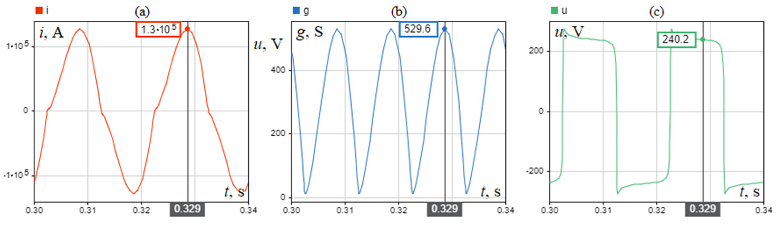
3.2. Power Supply System with Zero Resistance

For the calculations, it was assumed that the resistance of the arc receiver power supply system was zero Rs = 0 Ω. This approach made it possible to determine the operating conditions of the system if it were made entirely of superconducting elements that were constantly in a superconducting state (Rhts = 0). The simulation was performed for two arc lengths of l = 1 cm (Figure 6) and 20 cm (Figure 7).
The simulation shows that the maximum current for the l = 1 cm arc is Im = 181.1 kA and is 53.9 kA higher than the maximum current for the 20 cm arc. The voltage of the 1 cm arc at the instant of time when the current reaches its maximum value is U = 50 V and is 190 V lower than for the 20 cm arc. The conductance of the 1 cm arc reaches a maximum value of G = 3.6 kS and is 3.1 kS higher than for the 20 cm arc.
Comparing the results obtained for a circuit with a resistance of Rs = 0.38 mΩ with the results obtained for a circuit with a resistance of Rs = 0 Ω, it is apparent that making the power circuit from a superconductor which is constantly in a superconducting state increases the arc current by 3.2 kA for an arc of 1 cm length, which is a 1.8% increase in value. There is also an increase in the conductance of such an arc by 74 S, which is a 2% increase. For a 20 cm arc, the use of a superconductor in the power supply system increases the arc current by 13.9 kA, a 1% increase, and the conductance of the arc by 58 S, a 11% increase. The arc voltage remains unchanged. The results obtained from the simulations are summarised in Table 3.

3.3. Power System with a Superconductor Losing its Superconducting State

A superconductor plugged into the direct power circuit of an arc furnace can, as it were, act as a resistance switch for that circuit. Such a circuit may be in a low resistance state when the superconductor is in a superconducting state, or a high resistance state when the superconductor is in a resistive state. The parameters that determine the switching are the value of the current taken by the arc and the current critical value of the superconductor. By selecting the ratio of the critical current of the superconductor to the current taken by the arc, it is possible to decide when the superconducting state is lost.
The circuit in Figure 1 was analysed assuming that the resistance Rs is equal to 0.38 mΩ. It was also assumed that the superconducting resistance Rhts varies stepwise as shown in Figure 2. The lower value of this resistance, i.e., in the superconducting state, was assumed to be Rhts = 0 Ω, while for the upper value, i.e., in the resistive state, Rhts = 1 mΩ was assumed for the first case under consideration or Rhts = 100 mΩ for the second case under consideration. The adoption of the two values of the superconductor in the resistive state for the calculations made it possible to determine the degree of influence of the superconductor resistance value on the operation of the circuit with an electric arc. The analysis also took into account different values of the critical current of the superconductor. The effects on the arc and electrical circuit of a superconductor with several values of the critical current adopted from the range from Ic = 60% Im to Ic > 100% Im, where Im = 177,889 A (Table 3) were analysed.
For a critical current greater than 100% Im, in no case does the superconductor come out of superconductivity and the circuit operation is identical to that discussed in Chapter 3A. For a superconductor critical current lower than 100% Im, the value of the critical current affects the values of arc currents, voltages and conductances measured for different arc lengths. The characteristics of changes in the maximum values of these parameters as a function of changes in the arc length and at different values of the critical current are presented in Figure 8, Figure 9 and Figure 10.
Figure 8 shows that when the maximum value of the arc current exceeds the critical value of the superconducting current, 3 areas can be distinguished on the characteristic curve I = f(l) at a change of arc length, as shown in Figure 11. In the first area (a), the arc current is damped [38,39] while maintaining its shape close to sinusoidal (Figure 12-a). In area two (b), the current is damped by flattening (cutting off) its peak (Figure 12-b). This flattening is clearly visible for large resistances of the superconductor in the resistive state. In the third region (c), current damping does not occur, and the current waveform is sinusoidal because the superconductor does not exit the superconducting state (Figure 12-c).
The effect of the critical current value is less noticeable in the case of the arc conductance (Figure 9). The greatest differences in conductance values, for different values of the superconductor critical current, are observed for small arc lengths.
The arc voltage does not depend on the value of the critical current of the superconductor and reaches the same value for any of its values at a given arc length (Figure 10).
In Figure 13, in addition to the waveforms of current (i), arc voltage (u) and its conductance (g), the changes in circuit resistance (r) are shown. The time intervals during which the superconductor is in the resistive state are visible as step changes in the circuit resistance from a value of 0.38 mΩ to a value of 1.38 mΩ. Figure 13a shows the case when the operating point of the circuit is selected on the part (a) of the characteristic curve shown in Figure 11. The case when the critical current of the superconductor Ic is 80% of the value of the maximum current Im (Ic = 80% Im) that flows in the circuit with the grid resistance equal to Rs = 0.38 mΩ and the arc length l = 1 cm (Im = 177,889 A, Table 3) is analysed. The characteristics in Figure 13b were obtained by moving the operating point of the circuit to the line (b) of the characteristics in Figure 11. This was done by changing the arc length to l = 13 cm.
The superconductor is in the resistive state for the longest time (Figure 13a) when the circuit operates on the curve (a) of the characteristic from Figure 11. On this curve, the current is limited while maintaining its shape close to sinusoidal. When the working point of the circuit passes to the linear part (b) of the characteristic from Figure 11, the time in which the superconductor is in the resistive state is shortened. In the intervals in which the superconductor is in the resistive state, the value of the current is reduced by cutting off (flattening) the peaks of its waveform to the value equal to the value of the critical current of the superconductor. A similar cut-off of the peaks is also observed in the arc conductance waveforms. Figure 13c shows the case when the superconductor does not leave the superconducting state and the resistance of the circuit is constant in time and equal to 0.38 mΩ, which corresponds to the operation of the circuit on the curve (c) of the characteristic from Figure 11. The length of the arc is then l = 17 cm.
With increasing resistance of the superconductor in the resistive state, the current damping becomes stronger and the range of the curve (a) in Figure 11 becomes narrower until it disappears completely for large values of superconducting resistance (Figure 14).
The real current waveforms obtained from numerical simulations are shown in Figure 15. Increasing the resistance of a superconductor in the resistive state to Rhts = 100 mΩ causes significantly larger changes in the arc conductance (Figure 16) than in the case of Rhts = 1 mΩ (Figure 9). The characteristics of the arc voltage variation as a function of changes in its length are the same for both considered superconductor resistances (Figure 10 and Figure 17).
Figure 18 shows the current, arc conductance, arc voltage and circuit resistance waveforms for three selected operating points on the characteristic of Figure 15. At a superconductor resistance in the resistive state of 100 mΩ there is a clear flattening (cut-off) of the current and arc conductance waveforms at times when the superconductor loses its superconducting state (Figure 18a,b). Figure 18c shows the case when the arc is long enough that the superconductor does not exit the superconducting state and the circuit resistance is constant in time and equal to 0.38 mΩ.
Relating these simulation results to the results presented in Figure 13, it is found that there are clear differences in the current waveforms in the arc length range from 1 cm to 12 cm. In this length range, at time instants when the superconductor exits the superconducting state and for Rhts = 100 mΩ, the maximum current value is constant and maintained at a value equal to the critical current value of the superconductor. At Rhts = 1 mΩ in the arc length range of 1 cm to 12 cm, during the time instants when the superconductor exits the superconducting state, the current value was variable and greater than the critical current of the superconductor. After the arc length exceeded 12 cm, the differences in current variation disappeared.
The analysis shows that by selecting the value of resistance of the superconductor in the resistive state and by selecting the value of the critical current, it is possible to influence the operating characteristics of the arc receiver. The value of the arc current and the value of the arc conductance can be influenced by shaping the course of variation of these quantities as a function of the arc length changes.

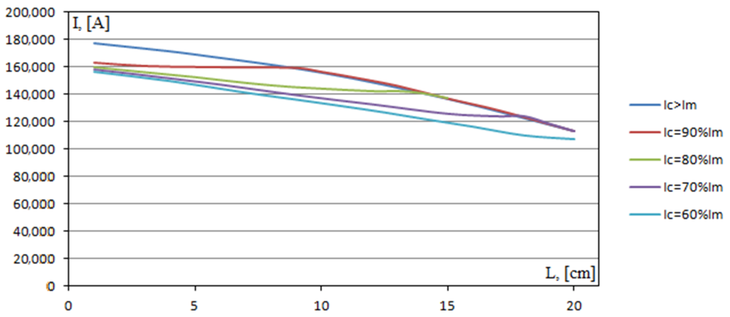
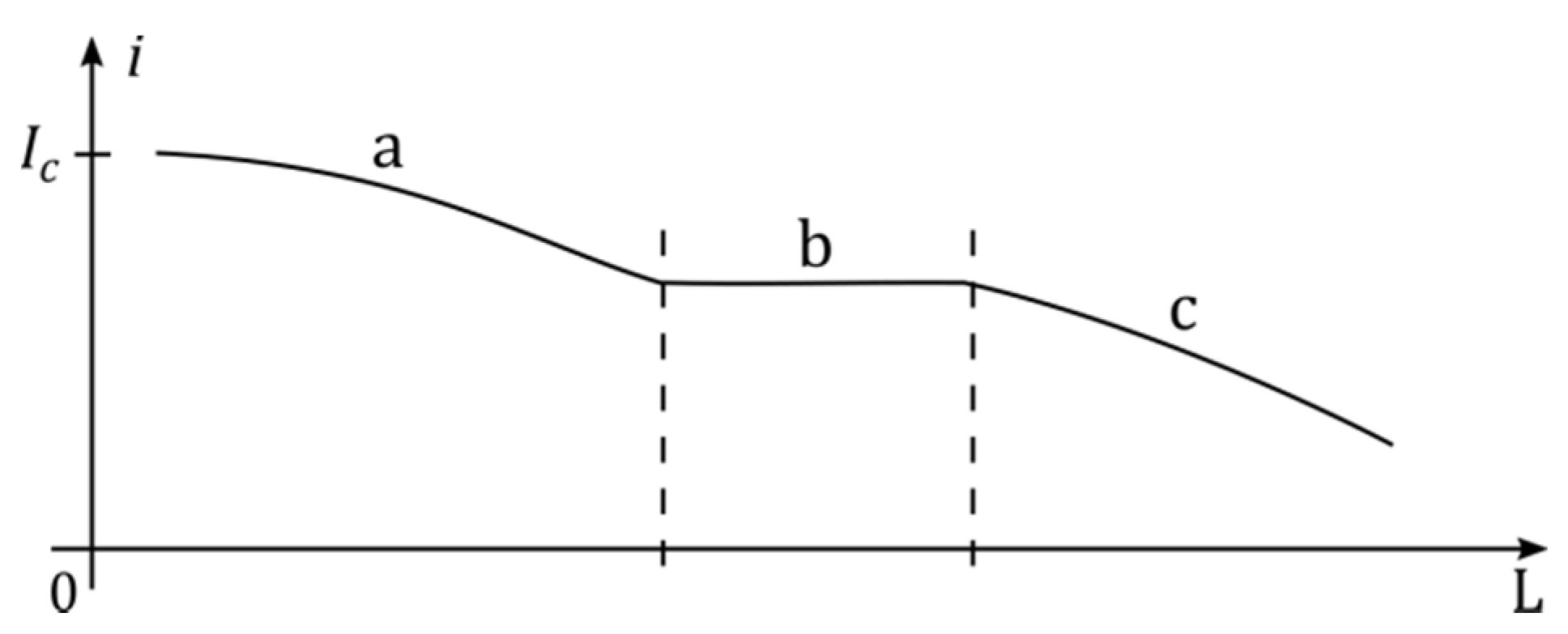
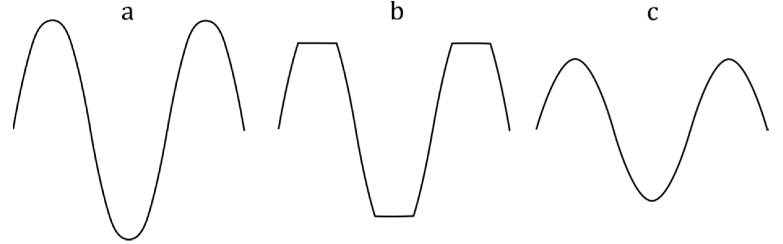
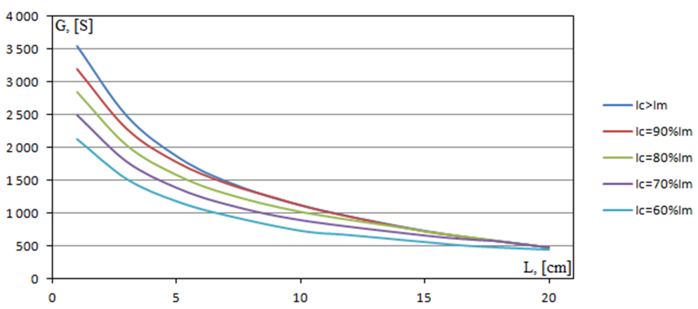
3.4. Variable-Length Electric Arc

The analysis of the cooperation of the power system equipped with a superconducting element with an arc of changing length was carried out in a modified system from Figure 3. The modification consisted in replacing the “Constant Larc” block with the system of blocks shown in Figure 19. This system generates an arc length varying randomly in time in the range from 0 to 20 cm as shown in Figure 20-l and Figure 21-l.
The analysis was performed for Ic = 80%Im, a circuit resistance of Rs = 0.38 mΩ and a resistance of the superconductor in the resistive state equal to Rhts = 100 mΩ.
As can be seen from Figure 20, the current in the circuit maintains a constant value of 142.4 kA in the range of arc lengths where the superconductor exits the superconducting state, i.e., for arc lengths from 0 to 15 cm. When the arc exceeds 15 cm in length, the maximum current values fall below the critical value for the superconductor. The minimum peak current value in this range is 119.2 kA.
Making the total circuit from a superconductor, i.e., Rs = 0 Ω, allows the maximum current value to be maintained at 142.4 kA in the arc length range from 1 cm to 16 cm (Figure 21). Thus, there is an extension of the arc length range in which the superconductor exits the superconducting state. In the arc length range from 16 cm to 20 cm, the superconductor is constantly in the superconducting state and the lowest peak current value is 136.1 kA, which is 16.9 kA higher than when Rs = 0.38 mΩ.

4. Conclusions

The numerical analysis carried out was aimed at analysing the cooperation of an arc receiver with a power supply circuit in which a superconducting element was connected in series in the current path.
The installation of a superconductor as an additional element in a typical arc power supply system, assuming a critical current value for the superconductor lower than the maximum value of the discharge current, has a significant effect on the operating characteristics of the system. The magnitude of this influence depends on the value of the ratio of the critical value of the superconductor current to the maximum value of the current with which the arc is supplied in a normal power system made of resistive materials. The smaller this ratio is than unity, the stronger the effect.
The value of the resistance of the superconductor in the resistive state of its operation is also significant. The strength of the interaction increases with the increase in the ratio of the value of the resistance of the superconductor in the resistive state to the resistance of the system. In the case analysed, for the resistance of the supply system equal to 0.38 mΩ, the resistance of the superconductor in the resistive state 100 mΩ, and the critical value of the superconductor current equal to 80% of the maximum value of the current attainable in the circuit without a superconductor, the maximum value of the current in the supply circuit of the arc receiver was limited and kept constant at 142.4 kA in the arc length range from 0 to 15 cm.
The elimination of the resistance of the power circuit by making the entire circuit from a superconductor widens the arc length range for which the maximum current value is kept at 142.4 kA. The maximum current for the arc length at which the superconductor does not leave the superconducting state is also increased. Making the complete power system from a superconductor while constantly maintaining it in a superconducting state leads to a 2% increase in the value of the arc current with a length of 1 cm and more than a 12% increase in the current with an arc length of 20 cm. Analogous increases occur when comparing the conductance of the arc.
The analysis shows that by selecting the critical value of the superconductor current and its resistance in the resistive operating state, the operating characteristics of the arc receiver can be influenced. In the range of small arc lengths, the superconductor acts as a current limiter by inserting additional resistance into the circuit. In the large arc length range, making the power circuit from a superconductor allows higher current values to be obtained by eliminating the resistance of the power circuit.

Funding

This research received no external funding.

Institutional Review Board Statement

Not applicable.

Informed Consent Statement

Not applicable.

Data Availability Statement

Not applicable.

Conflicts of Interest

The authors declare no conflict of interest.

References

  1. Facchini, F.; Mossa, G.; Mummolo, G.; Vitti, M. An Economic Model to Assess Profitable Scenarios of EAF-Based Steelmaking Plants under Uncertain Conditions. Energies 2021, 14, 7395. [Google Scholar] [CrossRef]
  2. Saboohi, Y.; Fathi, A.; Škrjanc, I.; Logar, V. Optimization of the Electric Arc Furnace Process. IEEE Trans. Ind. Electron. 2019, 66, 8030–8039. [Google Scholar] [CrossRef]
  3. Yakimov, I.A.; Gasiyarov, V.R. The Improvement of Operational Efficiency of High Power Electric Arc Furnace Due to Electrical Equipment. In Proceedings of the 2018 International Conference on Industrial Engineering, Applications and Manufacturing (ICIEAM), Moscow, Russia, 15–18 May 2018. [Google Scholar] [CrossRef]
  4. Jawahery, S.; Visuri, V.-V.; Wasbø, S.O.; Hammervold, A.; Hyttinen, N.; Schlautmann, M. Thermophysical Model for Online Optimization and Control of the Electric Arc Furnace. Metals 2021, 11, 1587. [Google Scholar] [CrossRef]
  5. Czapla, M.; Karbowniczek, M.; Michaliszyn, A. The optimisation of electric energy consumption in the electric arc furnace. Arch. Metall. Mater. 2008, 53, 559–565. [Google Scholar]
  6. Gajić, D.; Savić-Gajić, I.; Savić, I.; Georgieva, O.; Di Gennaro, S. Modelling of electrical energy consumption in an electric arc furnace using artificial neural networks. Energy 2016, 108, 132–139. [Google Scholar] [CrossRef]
  7. Bai, E. Minimizing energy cost in electric arc furnace steel making by optimal control designs. J. Energy 2014, 2014, 620695. [Google Scholar] [CrossRef] [Green Version]
  8. Milutinovich, J.S.; Mahon, W.T. Some Thoughts on Minimizing Cost of Arc-Furnace Transformers. IEEE Trans. Reliab. 1975, 24, 251–254. [Google Scholar] [CrossRef]
  9. Berger, A.; Cherevatskiy, S.; Noe, M.; Leibfried, T. Comparison of the efficiency of superconducting and conventional transformers. J. Phys. Conf. Ser. 2010, 234 Pt 3, 032004. [Google Scholar] [CrossRef]
  10. Manusov, V.Z.; Pavlyuchenko, D.A.; Ahyoev, J.S. A Study of Superconducting Transformer with Short-Circuit Current Limitation. Int. J. Electr. Comput. Eng. (IJECE) 2018, 8, 505–512. [Google Scholar] [CrossRef]
  11. Elshiekh, M.; Zhang, M.; Ravindra, H.; Chen, X.; Venuturumilli, S.; Huang, X.; Schoder, K.; Steurer, M.; Yuan, W. Effectiveness of Superconducting Fault Current Limiting Transformers in Power Systems. IEEE Trans. Appl. Supercond. 2018, 28, 5601607. [Google Scholar] [CrossRef]
  12. Ohtsubo, Y.; Iwakuma, M.; Sato, S.; Sakaki, K.; Tomioka, A.; Miyayama, T.; Konno, M.; Hayashi, H.; Okamoto, H.; Gosho, Y.; et al. Development of REBCO Superconducting Transformers with a Current Limiting Function—Fabrication and Tests of 6.9 kV–400 kVA Transformers. IEEE Trans. Appl. Supercond. 2015, 25, 5500305. [Google Scholar] [CrossRef]
  13. Ivanov, D.M.; Manusov, V.Z.; Semenov, A.V. Experimental Studies of a High-temperature Superconducting Prototype Transformer with Current Limiting Function. In Proceedings of the 2020 International Youth Conference on Radio Electronics, Electrical and Power Engineering (REEPE), Moscow, Russia, 12–14 March 2020. [Google Scholar] [CrossRef]
  14. Vaishnavi, B.V.; Angelin Suji, R.S.; Trivenishree, D.P.; Nidha, N.; Sowmya, G.J. Superconducting Fault Current Limiter & Its Application. Int. J. Sci. Eng. Res. 2016, 7, 126–134. [Google Scholar]
  15. Morandi, A. State of the art of superconducting fault current limiters and their application to the electric power system. Phys. C Supercond. 2013, 484, 242–247. [Google Scholar] [CrossRef]
  16. Cho, K.-C.; Park, M.-K.; Lim, S.-H. Analysis of the DC Fault Current Limiting Characteristics of a DC Superconducting Fault Current Limiter Using a Transformer. Energies 2020, 13, 4210. [Google Scholar] [CrossRef]
  17. Noe, M.; Hobl, A.; Tixador, P.; Martini, L.; Dutoit, B. Conceptual Design of a 24 kV, 1 kA Resistive Superconducting Fault Current Limiter. IEEE Trans. Appl. Supercond. 2012, 22, 5600304. [Google Scholar] [CrossRef]
  18. Song, W.; Pei, X.; Alafnan, H.; Xi, J.; Zeng, X.; Xiang, B.; Liu, Z. Experimental and Simulation Study of Resistive Helical HTS Fault Current Limiters: Quench and Recovery Characteristics. IEEE Trans. Appl. Supercond. 2021, 31, 5601106. [Google Scholar] [CrossRef]
  19. Xi, J.; Pei, X.; Song, W.; Xiang, B.; Liu, Z.; Zeng, X. Experimental tests of DC SFCL under low impedance and high impedance fault conditions. IEEE Trans. Appl. Supercond. 2021, 31, 5601205. [Google Scholar] [CrossRef]
  20. Dew-Hughes, D. The critical current of superconductors: An historical review. Low Temp. Phys. 2001, 27, 713–722. [Google Scholar] [CrossRef] [Green Version]
  21. Talantsev, E. On the fundamental definition of critical current in superconductors. arXiv 2017, arXiv:1707.07395. [Google Scholar]
  22. Mimura, T.; Masuda, T.; Yaguchi, H.; Fukushima, H. Recent Progress of the High-Temperature Superconducting Cable Project in Japan. 31nternational Symposium on Superconductivity (ISS2018). J. Phys. Conf. Ser. 2019, 1293, 012066. [Google Scholar] [CrossRef]
  23. Cheetham, P.; Viquez, J.; Kim, W.; Graber, L.; Kim, C.H.; Pamidi, S.V. High-Temperature Superconducting Cable Design Based on Individual Insulated Conductors. Adv. Mater. Sci. Eng. 2018, 2018, 3637873. [Google Scholar] [CrossRef] [Green Version]
  24. Tsotsopoulou, E.; Dyśko, A.; Hong, Q.; Elwakeel, A.; Elshiekh, M.; Yuan, W.; Booth, C.; Tzelepis, D. Modelling and Fault Current Characterization of Superconducting Cable with High Temperature Superconducting Windings and Copper Stabilizer Layer. Energies 2020, 13, 6646. [Google Scholar] [CrossRef]
  25. Lee, S.-J.; Kang, S.Y.; Park, M.; Won, D.Y.; Yoo, J.; Yang, H.S. Performance Analysis of Real-Scale 23 kV/60 MVA Class Tri-Axial HTS Power Cable for Real-Grid Application in Korea. Energies 2020, 13, 2053. [Google Scholar] [CrossRef]
  26. Fang, X.; Wang, B.; Yu, M.; Zhang, L. Research on State Acquisition for Electric Arc Furnace Under Multivariate Combination Model. In Proceedings of the Chinese Automation Congress (CAC), Xi’an, China, 30 November–2 December 2018; IEEE: Piscataway, NJ, USA, 2018. [Google Scholar] [CrossRef]
  27. Esfahani, M.T.; Vahidi, B. A New Stochastic Model of Electric Arc Furnace Based on Hidden Markov Model: A Study of Its Effects on the Power System. IEEE Trans. Power Deliv. 2012, 27, 1893–1901. [Google Scholar] [CrossRef]
  28. Čerňan, M.; Tlustý, J. Model of Electric Arc Furnace for designing of power quality improvement equipment, IEEE. In Proceedings of the 15th International Scientific Conference on Electric Power Engineering (EPE), Brno-Bystrc, Czech Republic, 12–14 May 2014. [Google Scholar] [CrossRef]
  29. Bhonsle, D.C.; Kelkar, R.B. Design and analysis of composite filter for power quality improvement of electric arc furnace. In Proceedings of the 3rd International Conference on Electric Power and Energy Conversion Systems, Istanbul, Turkey, 2–4 October 2013; IEEE: Piscataway, NJ, USA, 2013. [Google Scholar] [CrossRef]
  30. Awagan, G.R.; Thosar, A.G. Mathematical Modeling of Electric Arc Furnace to Study the Flicker. Int. J. Sci. Eng. Res. 2016, 7, 684–695. [Google Scholar]
  31. Lee, H.-J.; Kim, J.-S.; Kim, J.-C.; Yun, S.-Y.; Cho, S.-M. Study on Operational Characteristics of Protection Relay with Fault Current Limiters in an LVDC System. Electronics 2020, 9, 322. [Google Scholar] [CrossRef] [Green Version]
  32. Ko, S.-C.; Han, T.-H.; Lim, S.-H. Magnetizing Characteristics of Bridge Type Superconducting Fault Current Limiter (SFCL) with Simultaneous Quench Using Flux-Coupling. Energies 2020, 13, 1760. [Google Scholar] [CrossRef] [Green Version]
  33. Zhang, X.; Ruiz, H.S.; Geng, J.; Shen, B.; Fu, L.; Zhang, H.; Coombs, T.A. Power flow analysis and optimal locations of resistive type superconducting fault current limiters. SpringerPlus 2016, 5, 1972. [Google Scholar] [CrossRef] [Green Version]
  34. Falkowski, M.; Kowalczyk, A.; Strydom, A.M.; Reiffers, M.; Toliński, T. Inhomogeneous Superconducting Behaviour in La5Ni2Si3. J. Low Temp. Phys. 2017, 189, 120–131. [Google Scholar] [CrossRef] [Green Version]
  35. Bortolozo, A.D.; Gueiros, A.D.; Alves, L.M.S.; dos Santos, C.A.M. Influence of the Fluoride Atoms Doping on the FeSe Superconductor. Mater. Sci. Appl. 2012, 3, 22903. [Google Scholar] [CrossRef] [Green Version]
  36. Sun, F.; ZhongnanGuo, Z.; Zhang, H.; Yuan, W. S/Te co-doping in tetragonal FeSe with unchanged lattice parameters: Effects on superconductivity and electronic structure. J. Alloy. Compd. 2017, 700, 43–48. [Google Scholar] [CrossRef]
  37. Yazdani-Asrami, M.; Staines, M.; Sidorov, G.; Eicher, A. Heat transfer and recovery performance enhancement of metal and superconducting tapes under high current pulses for improving fault current-limiting behavior of HTS transformers. Supercond. Sci. Technol. 2020, 33, 095014. [Google Scholar] [CrossRef]
  38. Xiang, B.; Gao, L.; Junaid, M.; Liu, Z.; Geng, Y.; Wang, J.; Yanabu, S. Effects of Magnetic Fields on Quench Characteristics of Superconducting Tape for Superconducting Fault Current Limite. Appl. Sci. 2019, 9, 1466. [Google Scholar] [CrossRef] [Green Version]
  39. Kozak, S. Superconducting Surge Current Limiter. Energies 2021, 14, 6944. [Google Scholar] [CrossRef]
Figure 1. Circuit with arc and superconducting element; e-sinusoidal power supply, Rs-resistance of supply circuit, Ls-supply circuit inductance, Rhts-superconducting resistance.
Energies 15 02553 g001
Figure 2. Loss of superconducting state: (a) simplified superconducting transition characteristics, (b) changes in superconducting resistance.
Energies 15 02553 g002
Figure 3. Scheme of circuit with arc and superconducting element (Matlab Simulink).
Energies 15 02553 g003
Figure 4. Curves for Rs = 0.38 mΩ and arc length 1 cm: (a) current, (b) conductance, (c) voltage.
Energies 15 02553 g004
Figure 5. Curves for Rs = 0.38 mΩ and arc length 20 cm: (a) current, (b) conductance, (c) voltage.
Energies 15 02553 g005
Figure 6. Curves for Rs = 0 Ω and arc length 1 cm: (a) current, (b) conductance, (c) voltage.
Energies 15 02553 g006
Figure 7. Curves for Rs = 0 Ω and arc length 20 cm: (a) current, (b) conductance, (c) voltage.
Energies 15 02553 g007
Figure 8. Dependence of the current value on the arc length for selected critical current values of a superconductor (Rhts = 1 mΩ).
Energies 15 02553 g008
Figure 9. Dependence of the conductance value on the arc length for selected values of the critical current of a superconductor (Rhts = 1 mΩ).
Energies 15 02553 g009
Figure 10. Dependence of the voltage on the arc length for selected values of the critical current of a superconductor (Rhts = 1 mΩ).
Energies 15 02553 g010
Figure 11. Theoretical characteristics of current variation as a function of arc length for Im > Ic.
Energies 15 02553 g011
Figure 12. Theoretical current waveforms corresponding to the individual characteristic areas of Figure 11.
Energies 15 02553 g012
Figure 13. Time waveforms: current (i), arc conductance (g), circuit resistance (r), arc voltage (u) at three points of work (Figure 8 and Figure 11): (a) for l = 3 cm and Ic = 80% Im, (b) for l = 13 cm and Ic = 80%Im, (c) for l = 17 cm and Ic = 80% Im.
Energies 15 02553 g013
Figure 14. Theoretical characteristics of current variation as a function of arc length for Im > Ic and large values of superconducting resistance in the resistive state.
Energies 15 02553 g014
Figure 15. Dependence of the current value on the arc length for selected critical current values of a superconductor (Rhts = 100 mΩ).
Energies 15 02553 g015
Figure 16. Dependence of the voltage on the arc length for selected values of the critical current of a superconductor (Rhts = 100 mΩ).
Energies 15 02553 g016
Figure 17. Dependence of the voltage on the arc length for selected values of the critical current of a superconductor (Rhts = 100 mΩ).
Energies 15 02553 g017
Figure 18. Time waveforms: current (i), arc conductance (g), circuit resistance I arc voltage (u) at three points of work (Figure 15): (a) for l = 3 cm and Ic = 80%Im, (b) for l = 13 cm and Ic = 80% Im, (c) for l = 17 cm and Ic = 80% Im.
Energies 15 02553 g018
Figure 19. Changing the configuration of the diagram in Figure 3.
Energies 15 02553 g019
Figure 20. Time waveforms: current (i), arc conductance (g), circuit resistance (r) arc voltage (u) and arc lengths (l) for Ic = 80% Im and Rs = 0.38 mΩ.
Energies 15 02553 g020
Figure 21. Time waveforms: current (i), arc conductance (g), circuit resistance (r) arc voltage (u) and arc lengths (l) for Ic = 80% Im and Rs = 0 Ω.
Energies 15 02553 g021
Table 1. Electrical circuit parameters adopted for calculations.
ParameterValue Used for Calculation
Rs0.38 mΩ
Ls8.589 μH
Em500 V, 50 Hz
Rhts0 Ω in a superconducting state
1 mΩ or 100 mΩ in resistive condition
Table 2. Arc parameters adopted for calculations.
Parameter DescriptionParameterValue Used for Calculation
Constant defining the momentarily constant steady state arc voltage E0A40 V
Constant defining the momentarily constant steady state arc voltage E0B10 V/cm
Arc lengthl0–20 cm
Transition currentI010 A
Minimum arc conductancegmin0.008 S
Momentary power lossP0110 W
Time ConstantΘ0110 μs
Time ConstantΘ1100 μs
Constantα0.0005 A
Table 3. Simulation results for different circuit resistances.
Rs, [mΩ]l, [cm]Im, [A]G, [S]U, [V]
0.381177,889355750
20113,254471240
01181,144363150
20127,187529240
Publisher’s Note: MDPI stays neutral with regard to jurisdictional claims in published maps and institutional affiliations.

