1. Introduction
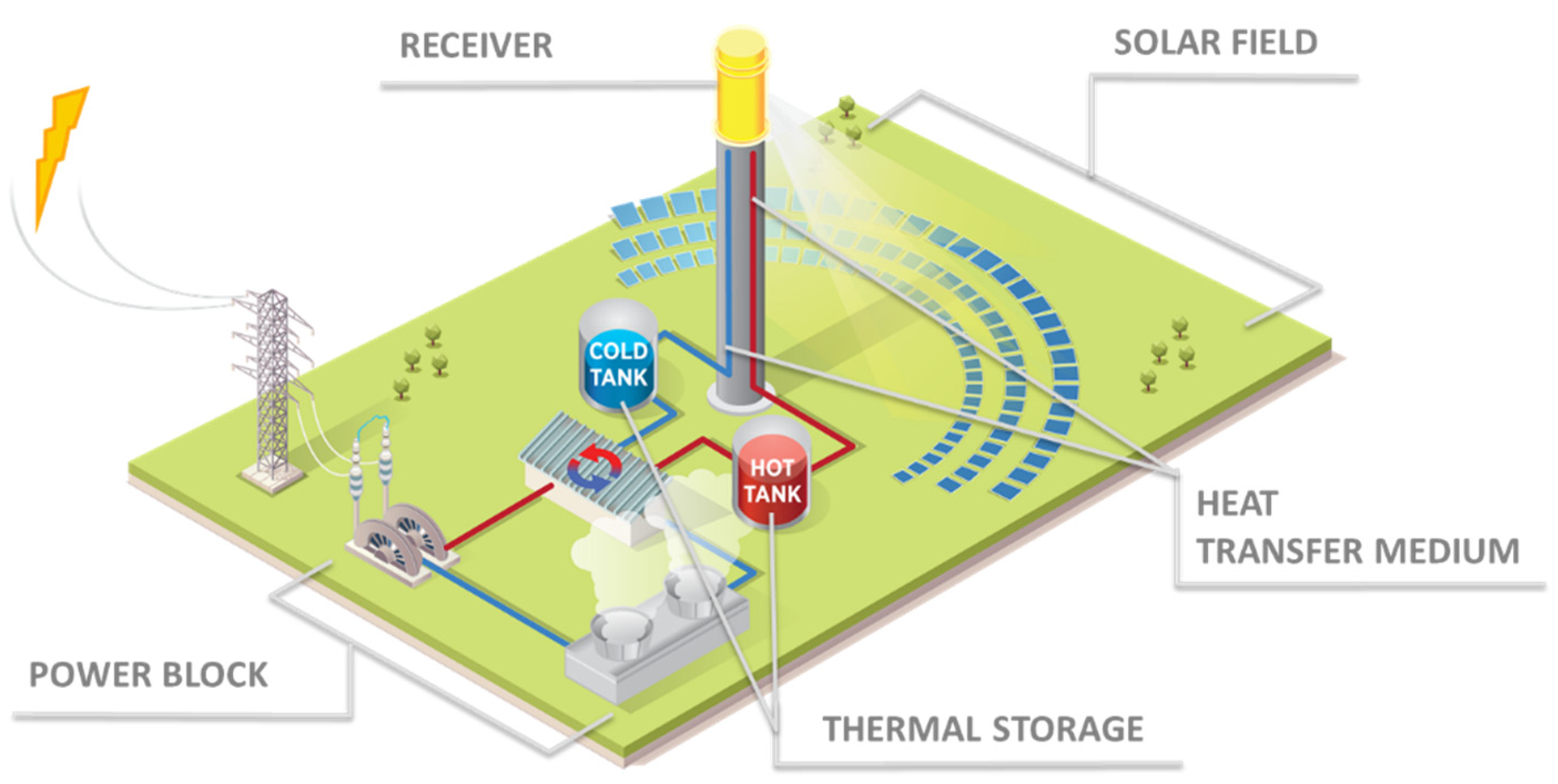
The solar receiver in a CST system is a unique heat exchanger transferring optical energy to a controllable heat transfer media (HTM). Traditional heat exchangers transfer thermal energy from one medium to another. In a solar power tower CST system, solar irradiation with a concentration on the order of 1000 suns (or 1000 kW/m2 flux assuming a direct normal irradiance of 1 kW/m2) effectively replaces one of the fluids in this heat exchanger paradigm. The other side of the heat exchanger is the CST system’s HTM, which can be used to provide energy to a TES reservoir, drive a power cycle or process heat application, or drive an endothermic chemical reaction. In solar power tower commercial applications, tubular receivers made from nickel-based superalloys are used to exchange energy to a molten salt or steam HTM.
For many CST applications, high temperatures are necessary to enable a broad applicability or technoeconomic viability. To achieve higher temperatures efficiently, high solar concentration ratios are generally required to minimize black body radiation losses and minimize the receiver size. However, strong solar fluxes create greater temperature gradients in the solar receiver and therefore greater thermal stress. Developing an optimized receiver for many CST applications requires optimizing the limits of both material mechanical properties and system thermal transport control in often narrow design and performance windows. Successful development of a cost-effective system for extreme temperature and flux applications will likely enable the greatest market impact for low-cost electricity production, high value thermochemical processes, and long duration TES. Increased temperature flexibility, control, and practical system integration of the receiver with TES is necessary to maintain the high value dispatchability of the system. (Note: Systems may directly use the HTM as a TES media, where significant co-optimization of the Receiver and TES subsystems are needed to enable the single HTM. Converseley, systems may use separate TES and HTM media. In this case exergetic losses in heat exchange must be considered in system optimization- often increasing the receiver temperature)
A schematic of a CST power tower is shown in
Figure 1. This layout using a central receiver is advantageous for both its scalability as well as the inherent ability to achieve uniquely high temperatures at the solar receiver. Commercially mature solar parabolic trough technologies’ maximum temperature is limited due to low achievable solar concentration ratio of the system. The earliest power tower demonstration projects at scales of several megawatts took place in Japan, Italy, France, Spain, and Europe, and the US in the 1980s [
1,
2]. Molten salt power tower receivers continued to advance, achieving a 42 MW feasibility proof at the US demonstration project, Solar Two, [
3] and 55 MW scale operation in the Spanish plant, PS10 [
4]. These projects and others led to commercial deployment of CSP receivers able to provide heat for a traditional 550 °C steam Rankine power cycle [
5]. However, the systems enabled by these receiver technologies have not resulted in broad deployment in any specific market. An improved technoeconomic case is needed for CST to become generally competitive with traditional sources of energy [
6]. Perhaps the largest lever to enabling cost competitive CST for electricity generation is enabling a more efficient power cycle. This can only be done if there is a newly-proven, effective receiver to support increased turbine temperatures.
Like heat exchangers, thermal reactors, and other thermal power system components, the risk and performance understanding of the component changes with size. A novel receiver tested in a laboratory environment at a scale significantly less than a megawatt is not directly translatable to a 10–1000 MW commercial solar power tower. Unlike many electrical power systems (such as photovoltaics and lithium-ion batteries) that are inherently modular, a multiscale design and testing perspective must be realized for novel receiver development. For example, models for HTM thermal gradients validated against a laboratory scale experiments could easily fail to capture the dynamics of HTM in 10 m long tubes, leading to undesirable effects like unexpected freezing. Inaccuracies in analyzing the thermal stress of a component may be unnoticeable until the stress build up in a full-scale system causes failure at a joint or interconnect. The impact of manufacturing variation is often unnoticeable in one-off and small-scale components. Despite such size-related risks, building and testing new ideas at massive scales is not a cost-effective strategy. A research strategy centered on de-risking technical challenges as they would manifest in the commercial environment is necessary for commercial adoptions.
Reviews of novel receiver concepts can be found in the literature [
7,
8]. The subsequent sections of this paper are intended to provide adequate context to focus innovations for high impact solar receivers or solar thermochemical reactors.
Section 2 describes the broad risk framework that must be overcome for a novel concept or component.
Section 2.1,
Section 2.2,
Section 2.3 and
Section 2.4 briefly discuss high level constraints to specific risks.
Section 3.1 explains the applications that have been the focus of USDOE funded R&D. In particular, the SunShot cost targets which have led to the development of a 750 °C Gen3 CSP system is presented. Finally,
Section 3.2 explains the USDOE’s receiver R&D goals for market relevant applications beyond the Gen3 CSP system.
2. Development Framework
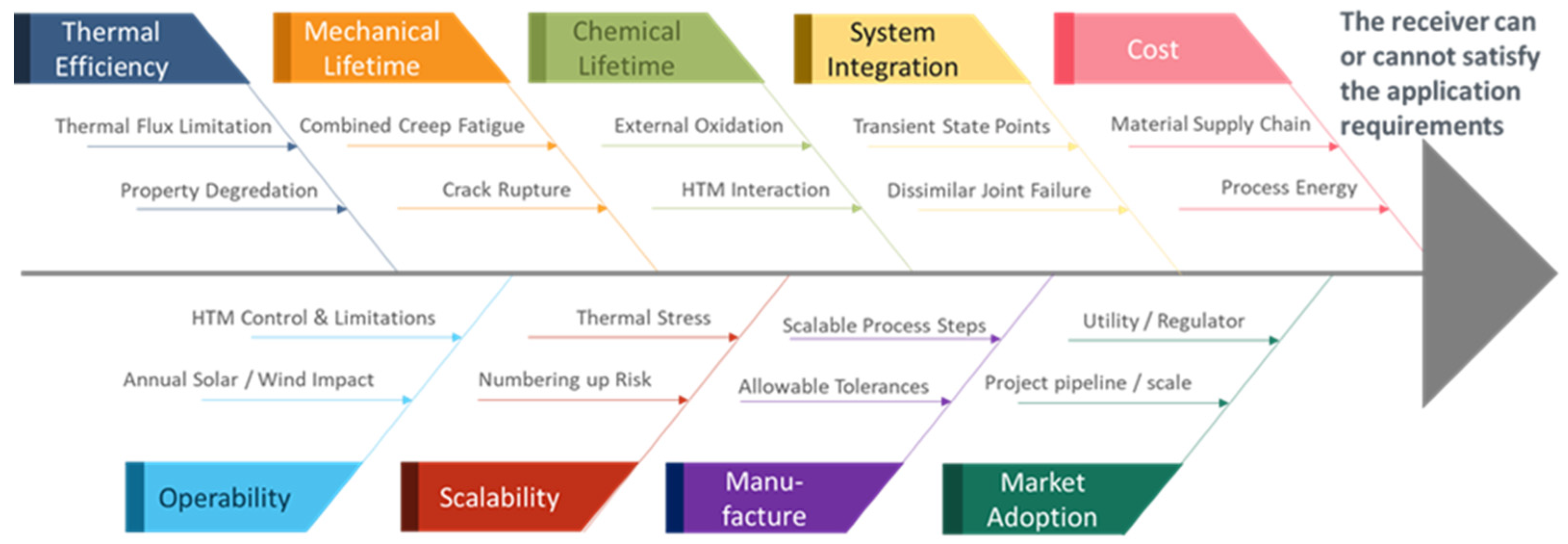
The risk profile for each CST receiver concept and HTM will vary widely. However, many considerations are universal and should be considered throughout the development cycle. Development must account for performance (efficiency), lifetime (mechanical and chemical), and cost. Implicit to these three attributes are the risks of scalable manufacturability, operability, and system integration. Often individual criteria cause hard limitations on the concept, such as fatigue limits of a material, size limits of a joining method, or response time to solar transient changes. Nuanced attributes such as these are often not fully considered in concept development. Rather than focusing only on the innovative scientific or engineering novelty of a receiver, evaluation of a range of potentially inhibiting criteria must be completed.
Figure 2 provides an example summary of these challenges. Unique concepts will need to prioritize different permutations of this construct. For each risk, unique metrics related to both acceptance minimum requirements as well as the degree of confidence that the aspect of the receiver can accomplish the needed objective can be developed.
2.1. Thermal Efficiency and Operability
Solar power systems are evaluated by the percentage of incident sunlight that becomes usable electricity. Taking advantage of every available photon minimizes cost and land requirements. The receiver impacts system efficiency in three ways. First, it can limit the optical efficiency of the solar field by impacting the optical target size and heliostat aiming requirements. Second, its thermal equilibrium can cause radiation and convection losses to the environment. Third, it can impose additional transport work on the system due to pressure drop. Also, the receiver can significantly affect the exergetic efficiency of the system, as any additional temperature drops imposed by the receiver can impact the peak temperature of the system and the overall second law of thermodynamics losses in the system. This has the practical implication of imposing greater technical requirements—and cost—on the heliostat field quality. Optimization methodologies must be developed that respect these tradeoffs before a realistic thermal efficiency can be described.
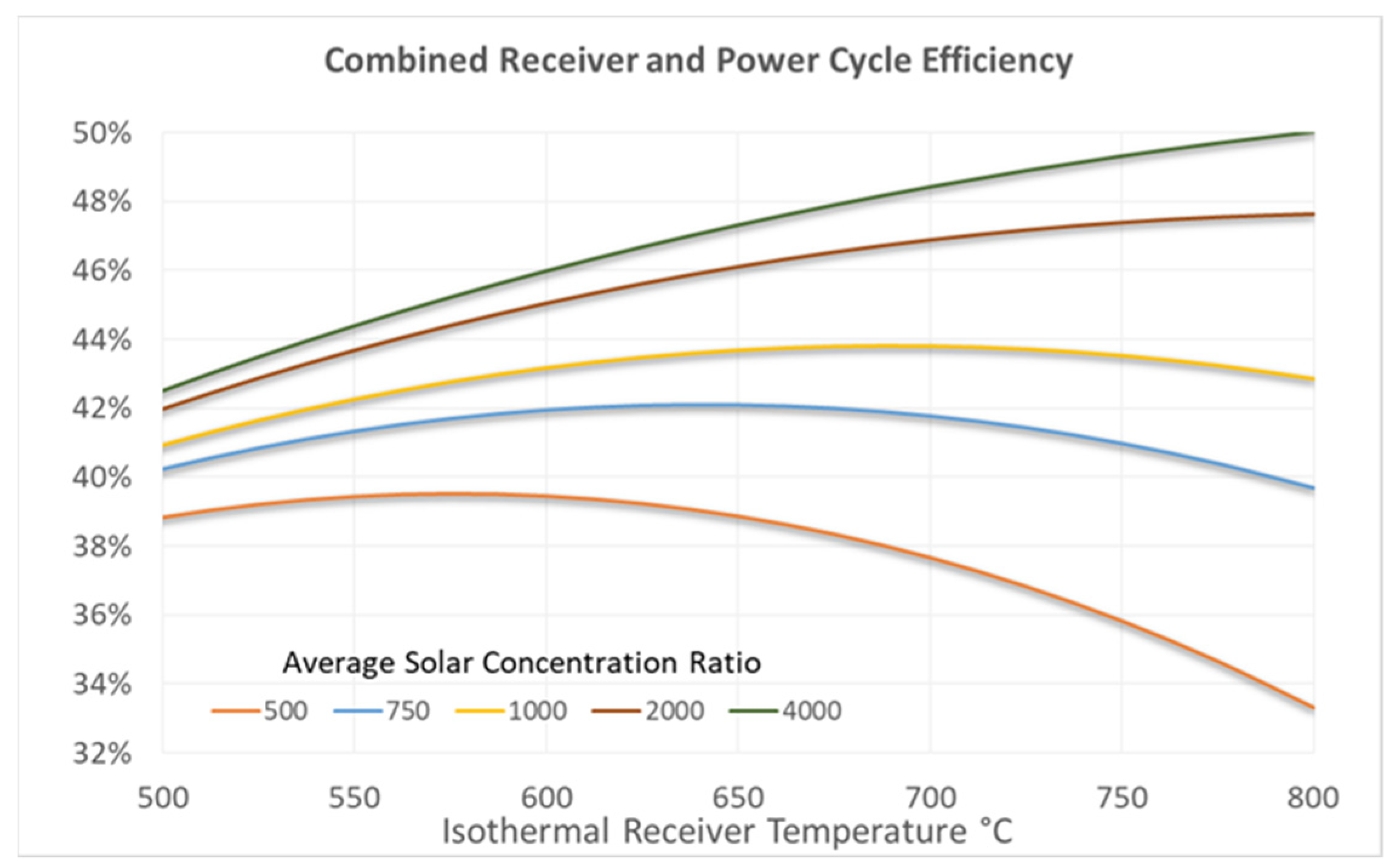
For many concepts with mechanical limits to the material properties, a maximum allowable thermal stress on the system poses a limit on the allowable incident solar flux (i.e., reducing the heliostat concentration ratio). This directly impacts black body emissive losses. Additionally, a resulting increase in the receiver size may increase convective losses and the system pressure drop.
Figure 2 shows a simplified quantification of the solar concentration ratio’s impact on a concentrating solar power (CSP) system’s thermal efficiency. The impact of temperature on the combined power cycle and receiver efficiency are shown for one scenario of varying solar concentration ratio. Enabling and demonstrating high solar flux on prototype receivers is necessary in many prototype development efforts [
9,
10,
11]. Limiting the allowable solar flux can be determinantal to receiver design. Note that there are many technical strategies to offsetting the decrease in efficiency with increasing temperature, including solar selective coatings and light trapping designs. Such strategies likely need to be employed to justify the challenges of developing high temperature systems.
Overlooked in the simplified analysis for
Figure 3 is that the variation in solar conditions throughout the year places another boundary condition on the receiver. There is not a single design point for the optical side of this heat exchanger. Thousands of unique solar inputs (sun position, heliostat response, and cloud transients) make up one set of conditions the receiver must perform under. For concepts that may have substantial convective losses, hundreds of unique wind loading profiles (directions and speeds, gusts and squalls) impact the receiver’s performance and control. Multiple groups have developed technoeconomic tools to evaluate this trade off space that incorporate realistic weather and dispatch models in the system [
12,
13].
Further complicating the performance profile are the thermal system’s operating modes, which may dictate the HTM flow rate (and change in flow rate). How the receiver system transitions through its start-up, shut-down, cloud transients, partial load events, and heliostat field anomalies can limit the viability of a concept. If design allowances preclude accommodating rapid changes in HTM or many solar field conditions, a significant portion of available solar energy may be missed. Alternatively, features such as rapid allowable start-up times, and robust accommodations to cloud or wind transients can measurably improve the levelized cost of energy. Such operational flexibility is likely a requirement for CST deployment in moderate DNI regions. Compounding the environment and thermal system’s impacts is essential to translate an optimistic “design point” receiver efficiency into an annualized performance that informs what the receiver can practically provide.
In summary, assessing thermal efficiency of a lab-scale prototype receiver should account for annualized performance by incorporating annualized conditions with transients. The tradeoff between constraining the solar field, the pressure losses in the system (or other exergetic losses), and the receiver’s thermal efficiency must be optimized within these conditions. The mechanical limits of the system will determine allowable thermal gradients and therefore system performance. De-risking the thermal efficiency of a receiver must account for the uncertainty in predicted thermal efficiency over this range of conditions. Receiver scale-up analysis should incorporate extrapolated uncertainties outside of any prototype design of experiments. Only then can one analyze if a novel receiver concept can provide the energy throughput needed to ensure the system performs adequately.
2.2. Receiver Lifetime and Materials
Power tower CST system capital costs typically must be amortized over financing terms on the order of 20 to 30 years to achieve levelized electricity costs that are commercially viable. Broadly, mechanical limits, chemical activity, and degradation or loss of the HTM constrain the lifetime of the receiver. Mechanical analysis of receivers using traditional materials is similar to mature heat exchanger methodologies. However, the impact of a solar flux profile and the HTM’s underlying flow profile and temperatures will cause more rapid material lifetime debits in certain sections of the receiver.
Receiver mechanical failures can generally be divided into three groups based on the material: time-independent ductile, time-dependent ductile, and time-independent brittle phenomena. Time-independent ductile materials include traditional low-temperature metals and novel materials such as MAX phase materials [
14] and cermets [
15] (ceramic–metal composites). They may fail due to plastic collapse, buckling, and fatigue. Current power tower receivers are made from time-dependent ductile materials: high temperature metals including steels. Failure in this class of alloys is initiated by creep rupture and creep-fatigue interactions. Design guidelines for such receivers have been established [
16]. Lastly, time-independent brittle materials such as ceramics and graphite fail due to brittle fracture and fatigue. While less systematically understood, developing a receiver from a brittle material will require the determination of the Weibull stress distribution based on data sets for the material’s temperature dependent expansion rate, elastic properties, thermal diffusivity, and other properties.
Mature materials have appropriate code cases governing their mechanical limitations for use in high temperature applications [
17]. In the absence of the coordinated effort needed to code qualify a material, component developers incorporating more novel materials are left needing to build a robust case of a predictable material lifetime. Directional heating and repetitive thermal cycling are critical to demonstrate the material is suitable for the application. Furthermore, advanced testing must incorporate materials at representative scales with representative property distributions consistent with full-scale manufacturing.
High temperature oxidation and corrosion caused by the HTM prevent the consideration of many materials and heat transfer fluids. In some cases, coating strategies may seem attractive to limit chemical degradation. However, without a mature understanding of the lifetime evolution of the coating and the probability of coating failure, other chemical degradation limiting strategies must be employed. Recently, many researchers have studied MgCl
2-based salt blends for a high temperature HTM [
18]. In such systems, oxygen or moisture incursion can cause catastrophic corrosion. Dynamic control systems that can respond to such events are necessary to maintain receiver operation and enable piping-wall thickness consistent with thermal efficiency and cost targets. Risk mitigation must incorporate a reliable controls strategy that can monitor and respond to corrosive events.
The cost and operability of maintaining HTM inventory may be a primary consideration in receiver design. For pressurized systems like supercritical carbon dioxide (sCO2) receivers, easily developed leaks may be fatal to plant operations. For open particle receiver concepts, the active loss of particles needs to be quantified and controlled. Particle losses can represent a significant replacement cost to the system, as well as cause safety risks at the facility, and may be coupled with aggressive convective losses. Development of novel receivers will not mature beyond laboratory studies without analysis and data on the lifetime limiting attributes. Accommodating these attributes will impact receiver efficiency, cost, and HTM control.
2.3. System Cost
The cost of a receiver system should account for the receiver panel (or the heat exchanging section of the receiver) as well as the movement of the HTM to and from the receiver (piping, pumping equipment, or equivalent). The cost is generally normalized by the receiver’s thermal duty. For high-temperature solar power towers, the USDOE has set a cost goal of
$120/kW
th for a 90% thermally efficient receiver with a 30-year lifetime as a baseline [
19]. If these technoeconomic targets can be achieved in tandem with heliostat cost reduction and adoption of an advanced power cycle, a CSP system can be cost competitive in the US electricity market. In current commercial applications, the receiver cost can be dominated by the nickel super alloy on the receiver panel. For higher-temperature CST systems, the USDOE found the cost of requiring nickel alloy piping traveling up and down the tower can be exorbitant and prohibitive to achieving cost targets in a conceptual 10 MW chloride salt CST system [
20]. The salt piping cost was estimated at several multiples of the
$120/kW
th target. Innovations are needed that enable the use of less material and less-expensive materials at high temperatures. Risk mitigation should account for supply chain limitations on selected materials.
2.4. System Integration and System Requirements
While early receiver technology development often precludes a detailed full CST system design, conceptually developing and refining the appropriate integrated system will remain a limiting factor for acceptance and development of the concept in more mature environments. At a minimum, the following attributes should be considered both practically and quantitatively:
Physical joining of repeated receiver parts as well as joining of the integrated receiver to the remainder of the system. In particular, material joining strategies and HTM control between subsystems should be understood.
The cascading impact of state points (temperature and pressure) in a system. A series of large temperature gradients or pressure drops can offset the benefits of the system.
The requisite control of the heliostat field to accommodate receiver requirements. Stringent requirements may cause an undesirable system due to heliostat cost or practical operation limitations.
The requisite control on the thermal transport system for a chemical reaction, power production rate, or integration with a realistic thermal transport system.
3. Applications
Without a viable market identified or a specified conceptual CST system, any solar receiver development remains academic. There would be no full-scale operation profile and system for integration design of the conceptual receiver. The system requirements are set by the needed dispatch requirements of the thermal system The ability to accommodate those dispatch requirements in an economically viable manner are determined by the operability and constraints of the solar collectors and receiver. In the best cases, a reasonably simple technoeconomic value can set the bounds for the system requirements. For process heat or electricity applications where the identified markets are not heavily reliant on responsive energy dispatch, the levelized cost of electricity (LCOE), storage (LCOS), or heat (LCOH) are generally appropriate, at least for an initial approximation. Many portions of a CST system have overlap with traditional thermal systems with reasonably well understood costs [
20,
21]. Heliostat costs are estimated regularly by the National Renewable Energy Laboratory (NREL) [
22]. They currently stand at
$100–
$150/m
2. The USDOE continues to pursue a cost target of
$50/m
2 for future heliostats [
6]. With assumptions about DNI and optimizing the amount of TES required, a practical price point for the system can be set and the available capital cost and required performance of the receiver defined. System technoeconomics generally require receivers with very high thermal efficiencies. Any loss in performance puts more burden on the heliostat field, which is already the most expensive subsystem in the CSP plant.
Markets beyond baseload electricity production or continuous process heat production are more challenging to broadly describe. Markets for electricity on demand can take many forms, including planned seasonal load demands [
23], planned nightly dispatch, or general plant availability for unforeseen demand (similar to a natural gas peaking plant). For many electricity applications, CSP with 8–16 h of TES is sufficient. However, long-term seasonal storage may be required in future grid scenarios [
24].
In non-electricity markets, such as industrial process-heat or chemical production, using CST to provide energy is not yet commercially mature. However, the large financial investment needed to develop and de-risk a first-of-its-kind CST system will require large markets to justify the cost. Niche markets ultimately may not support the amount of one-time engineering work required to develop a successful system.
3.1. SunShot
The USDOE’s largest CST focus over the past decade has been continuous electricity generation as defined in the SunShot (Note: SunShot cost targets developed by the USDOE are synonymous with the Solar Energy Technolies Office (SETO) cost targets. In general, they represent a cost point where solar energy production becomes cost competitive with traditional energy sources) mission [
19]. The USDOE SunShot Targets include the 2030 goal of 5¢/kWh LCOE for a baseload electricity producing CSP system with 12 h of thermal energy storage. In 2019, NREL analyzed the potential role of CSP in the US electricity market if the 5¢/kWh LCOE target for CSP in the United States were achieved [
6]. While projections into the future are subject to a variety of assumptions and scenarios, the analysis indicates that achieving the CSP SunShot cost target in 2030 would enable significant market-driven deployment of CSP in the following decades, potentially more than 100 GW of power generating capacity. The authors conclude that CSP with TES would be frequently deployed in a high-capacity factor system providing dispatchable, high-value services to the electricity system. The optimum generation profile would complement low-cost photovoltaic resources.
With the SunShot target as the defined objective, the USDOE initiated a series of programs since 2011 to improve the cost and performance of each CSP subsystem [
25]. To better delineate commercial CSP systems, a generational class of CSP technology can be defined by the maximum temperature of the system as summarized in
Table 1. The first generation of CSP, using parabolic trough collectors and a thermal oil HTM, has a maximum temperature of 400 °C. This limits the efficiency of the power cycle (approximately 37%) and the maximum change in temperature accessible in the TES system. The second generation of CSP is limited by its molten salt HTM known as Solar Salt (60% NaNO
3 40% KNO
3) to temperatures below 600 °C. This generation was enabled by heliostat fields charging a central receiver (a solar power tower) to achieve these higher temperatures and higher power cycle efficiency (approximately 42%). Other HTM, such as steam, have been shown to be operable in troughs and power towers. It is also conceivable that with careful design and risk consideration, Solar Salt can be used in trough systems at these temperatures. The shift from the first to second generations of CSP enabled the modeled LCOE to decrease from 21 to 9¢/kWh [
19]. As these systems have been commercially deployed, evaluation of the global operating fleet has revealed a number of practical failure mechanisms in all forms of solar receivers [
26].
Analysis of the subsystems’ capital costs, energy efficiencies, and integration bounds indicates the first two generations of CSP technology are unlikely to achieve a 5¢/kWh LCOE [
27]. System technoeconomic analysis makes it clear that power cycle efficiency remains one of the largest LCOE levers. Improving power cycle efficiency decreases the size of every component of the system, including removing the heliostats that are furthest from the tower and least efficient, as well as reducing the spatial dimensions of enormous TES vessels. The maximum power cycle efficiency, as dictated by the limits of Carnot’s theorem, can be improved by raising the temperature of the power cycle. Consequently, the HTM, TES, and the receiver’s maximum temperature must be similarly increased to develop a system concept consistent with the SunShot LCOE target. This consideration leads to a specific challenge for the solar receiver: the highest temperature component in the system must be made serviceable in more extreme conditions while achieving a reduced cost. The receiver must mechanically survive at a temperature and thermal stress limits of existing nickel super alloys.
This effort has culminated in the Gen3 CSP program where an identified power cycle, thermal transport system, and optical layout are the focus of innovation, long-term testing, and scale up [
28]. Again, increasing the peak temperature of the system is a critical enabling contributor to cost reductions. A supercritical CO
2 (sCO
2) Brayton power cycle operating at 720 °C for a 50% thermal to electric conversion efficiency has been identified as an enabling system for achieving the SunShot target. Critical advantages include high efficiency, scalability to small sizes, and compatibility with dry cooling. The power tower solar field layout deployed in commercial second generation CSP plants is likely an appropriate optical system for the SunShot target if further heliostat cost reductions can be achieved. This leaves the thermal transport system (particularly the receiver, HTM, and TES subsystem) as the least defined portion of a next generation CSP plant.
Building on the learnings of successive research initiatives since the launch of the SunShot initiative [
29], SETO developed a roadmap to connect disparate research learnings to the goal of developing an integrated, megawatt-scale thermal transport system consistent with the SunShot LCOE target, the heliostat field constraints, and the in-development of sCO
2 power cycle [
30]. The USDOE funded three system integration teams and several independent research and development teams to design and de-risk a viable high temperature thermal transport system concept [
28]. The system integration teams focused on overcoming challenges related to five down selection criteria to justify further investment in the systems:
The extent to which critical technology concerns have been de-risked
The team’s ability to execute testing on a greater than 1 MW integrated thermal transport pilot system
The feasibility of low-cost electricity in a 100 MW power plant with the proposed technology
The extent to which planned MW-scale integrated system testing further de-risks the technology
The extent to which the technology used in the 1 MW-scale integrated pilot system can be translated to a feasible full demonstration facility and ultimately a 100-MW scale commercial system
These criteria were developed to justify a
$25 million USD investment in continued scale up and risk reduction in the studied thermal transport system [
31].
3.1.1. A Liquid Pathway to SunShot Receiver Development
Prior to the Gen3 CSP program, USDOE invested in R&D campaigns to find viable liquid HTM that could be stable at higher operating temperatures [
32]. Ideally, if the liquid HTM were inexpensive, it could serve directly as the TES as well- making the plant look similar to Solar Salt power plants. Blends of MgCl
2-NaCl-KCl were identified as most promising for their high temperature stability, very low cost, and adequately low freezing temperature. Reliability of the piping and other containment materials were of primary scientific concern [
33]. NREL led an international research team to satisfy the Gen3 down selection criteria with a system utilizing the chloride salt blend [
34].
Their studies (along with international collaborators) indicate that corrosion risks from the chloride HTM can be handled if an active oxygen and moisture removal process can be integrated into the system [
35,
36,
37]. However, the team identified greater receiver risks caused by the salt’s poor thermal conductivity, the limitations of nickel alloy piping, and the freeze risks of the HTM in transient operation. For these reasons, the NREL team focused their system design on a liquid sodium receiver, which exchanged heat to the chloride salt blend at the top of the tower [
38]. The molten salt then served as the system’s TES. While corrosion risks in the sodium HTM likely remain, a feasible sodium receiver design for the system requirements was developed. A chloride salt receiver may remain feasible with further innovations, which were outside the time scope of NREL’s R&D.
3.1.2. Gen3 Particle Pilot Plant (G3P3) Receiver Development
For decades, researchers at Sandia National Laboratories’ (SNL) National Solar Thermal Test Facility have been actively developing particle-based receivers for CSP systems [
39,
40]. Other organizations in France, Germany, Australia, and Saudi Arabia have similarly focused on developing particle CSP systems [
41,
42,
43,
44]. SNL led an international collaboration to determine the feasibility of a particle-based Gen3 CSP system. Of the systems studied in the Gen3 CSP program, a particle system is likely the most unique compared to traditional CSP power towers. Most particle R&D teams have studied open receiver concepts with no barrier between the illuminated particles and the environment. This is simultaneously the greatest strength and challenge of the system. There is no risk of an intermediate alloy or other novel material failing during the receiver’s lifetime. There is, however, risk of substantial wind interaction with the system, poor thermal performance, and loss of particles.
SNL and its collaborators have predominantly focused on mitigating the impact of wind while increasing the controllability free falling particle receivers through the use of flow impediments [
45]. SNL has concluded that open particle receivers with impediments seem feasible, with annualized efficiencies greater than 80%. The team developed and validated thermal models of the flowing receiver [
46,
47,
48] and generated original technoeconomic analysis of a complete particle CSP system [
49,
50,
51]. These analyses showed both the potential viability of particle receivers at commercial scale as well as the consistency of a particle system with the SunShot cost targets.
3.1.3. Gen3 Gas Phase System Receiver Development
Existing CSP facilities, such as the Ivanpah Solar Electric Generating System, use the power cycle working fluid (steam) as the receiver’s HTM. In a similar fashion, Brayton Energy has led system development and integration of a concept where the sCO2 spinning the turbine is also circulated through the receiver. This avoids corrosion and freezing risks of salt, fire risks of sodium, and the wind impact of open particles. However, the increased pressure and temperature of the sCO2 compared to Ivanpah’s steam create the key receiver and system challenges.
The allowable thermal stress on nickel alloy piping can be particularly limiting on the receiver required to contain a high pressure and high temperature fluid. This led the research team to focus on design strategies and heliostat controls that maximized the receiver lifetime while still maintaining the required receiver HTM outlet temperature [
52]. Additionally, the energy cost to circulate (or move through compression) the sCO
2 is far greater than a lower temperature system. These challenges led Brayton Energy to develop a three-receiver system to minimize circulation energy in the system [
53]. Initial prototype test of the designed receiver is ongoing at the time of writing.
3.1.4. Gen3 Down-Selection and Path Forward
All three system integration teams placed tremendous emphasis on developing high-temperature receiver concepts and co-optimizing the receiver constraints with requirements of the complete thermal transport system. In all cases, designs satisfied a 30-year receiver lifetime and annualized environmental conditions, while maximizing system performance. Based on a merit review of the five previously stated down selection criteria, SNL’s G3P3 system was selected for pilot system build out and testing [
54]. Both the operational simplicity of the system, and the reduced overall material costs are key attributes for enabling consistency with the SunShot LCOE target.
3.2. CST Receivers beyond SunShot
In the near term, the development of Gen3 CSP systems represents a significant opportunity for enabling market driven buildout of CSP globally. However, the USDOE SunShot targets represent technoeconomic goals for a single application for a single conceptualization of CST systems: baseload electricity generation via sCO2 power cycles operating above 700 °C. Particles, chloride salts, or sCO2 receivers may prove best suited for systems different than the prescribed Gen3 architecture. Depending on further optimization of system designs, for various applications, as well as optimization of the heat transfer media themselves, each of these three systems may still benefit from significant redesign of the proposed receiver concepts. Applications for CST go beyond baseload electricity generation. USDOE-funded efforts are currently exploring applications including very long-duration TES, solar industrial process heat, and production of solar-thermal fuels and chemicals. A theme for many of these remains high-temperature, high-quality thermal energy transport, and storage.
In 2021, USDOE launched the SOLAR R&R program [
55] in recognition of the growing application space for CST receivers and to attempt to accelerate the transition from laboratory-scale innovations to market relevant pilot tests. This program challenges CST receiver developers to overcome both the broad de-risking requirements of a new receiver (as exemplified in
Figure 2) while developing solutions that can scale to commercial requirements. The same principles that allowed early R&D campaigns to inform the Gen3 program’s system integration teams, and ultimately produce credible system designs, may be employed organically to justify development of solar receivers for a broad range of applications. Pending continued congressional budget appropriations and departmental objectives, USDOE intends to continue to support strategic research, design, scale-up, testing, and commercialization of innovative solar receivers and solar thermochemical reactors.


