
Multi-Layered Numerical Model Development of a Standard Cylindrical Lithium-Ion Battery for the Impact Test


Abstract
:1. Introduction
2. Numerical Model for the Impact Test
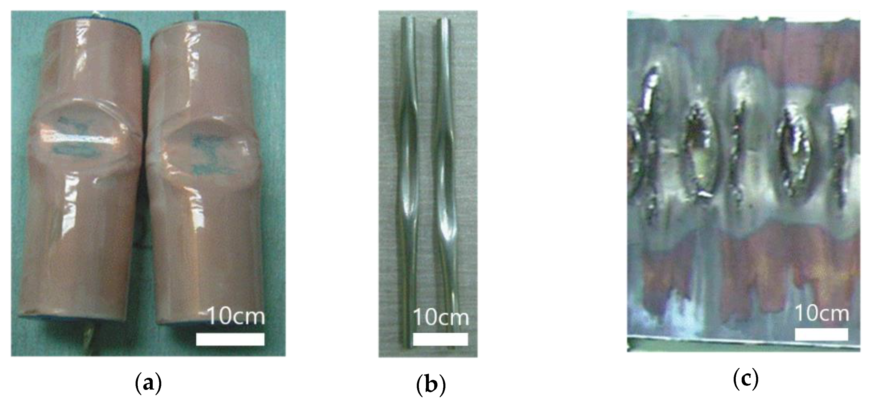
2.1. Impact Test Results
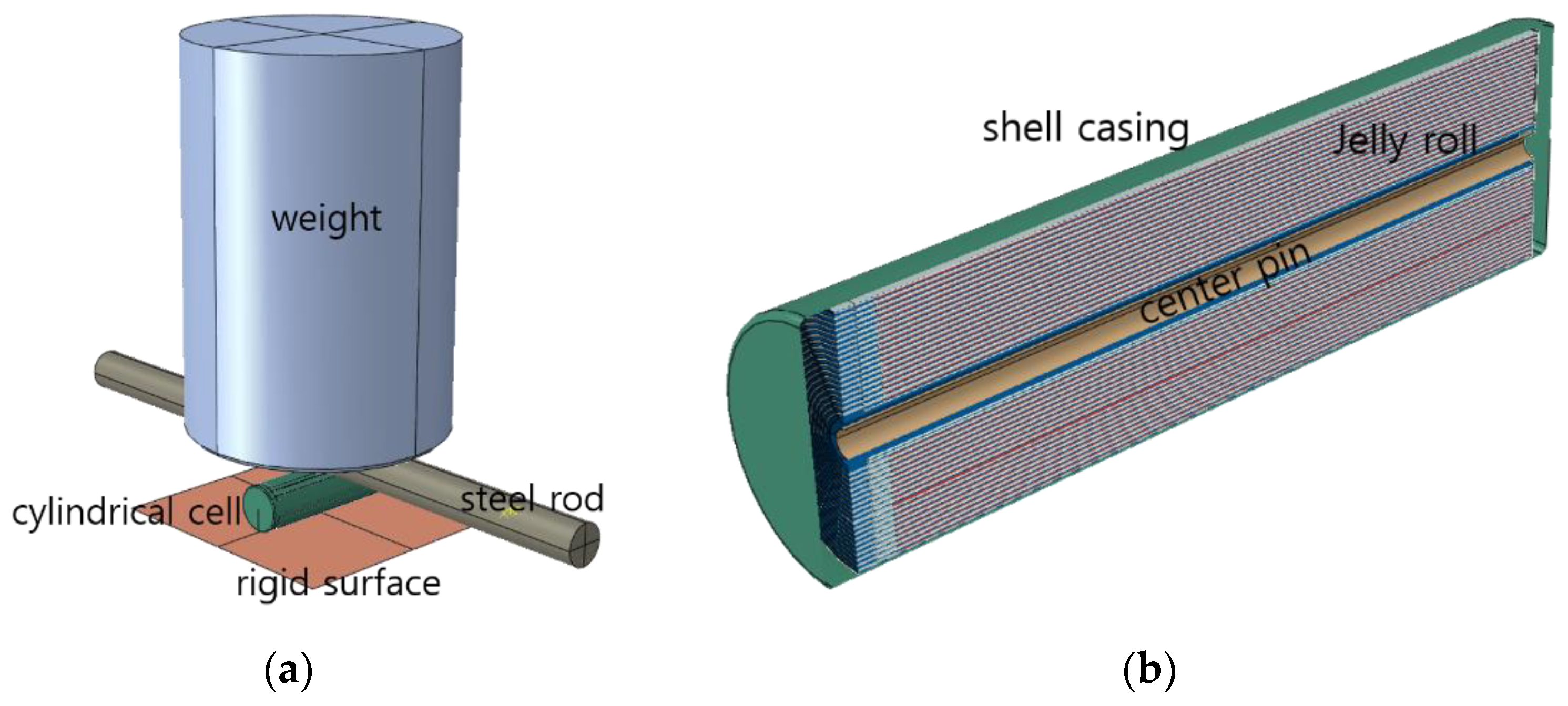
2.2. Numerical Model Development
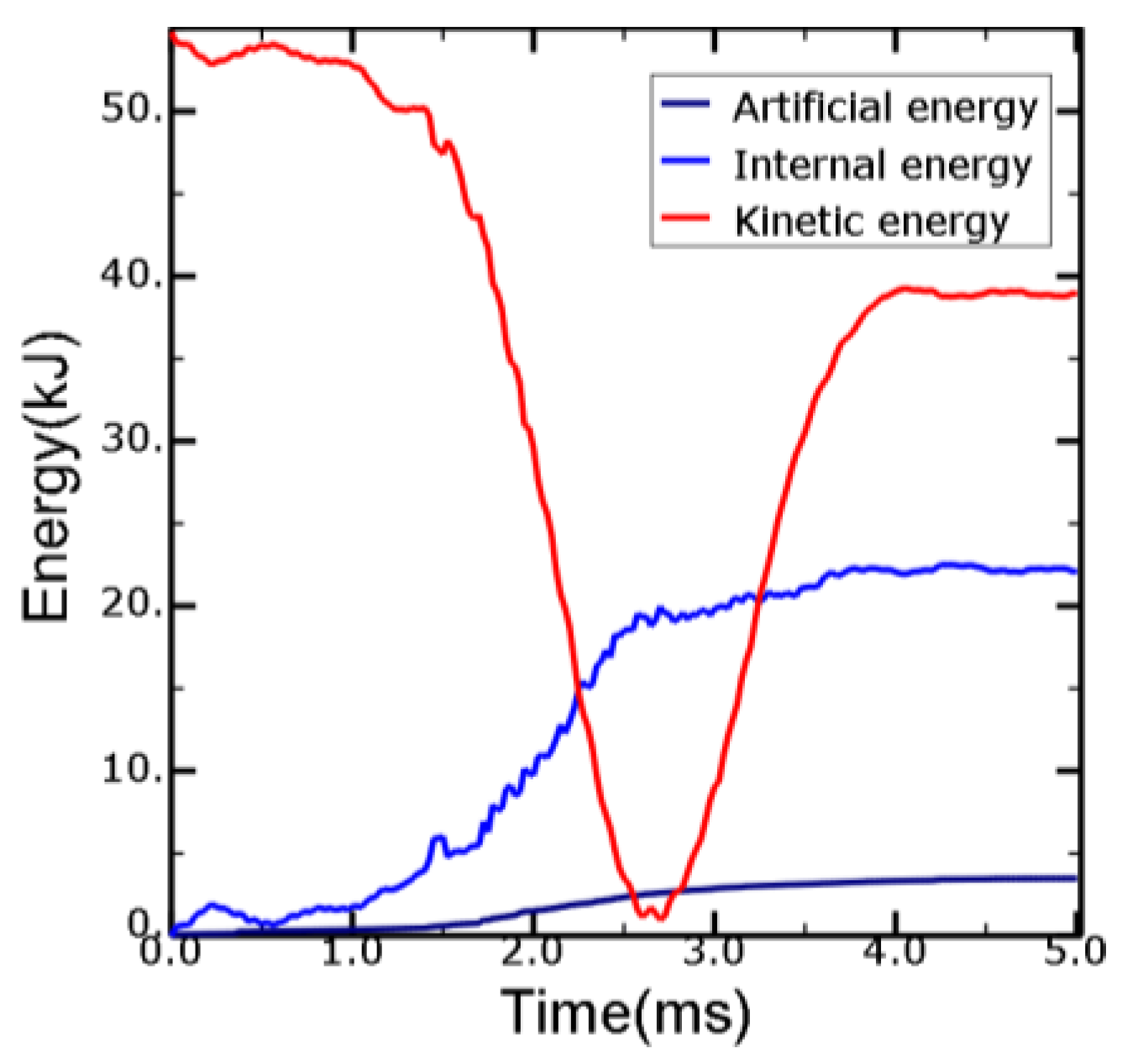
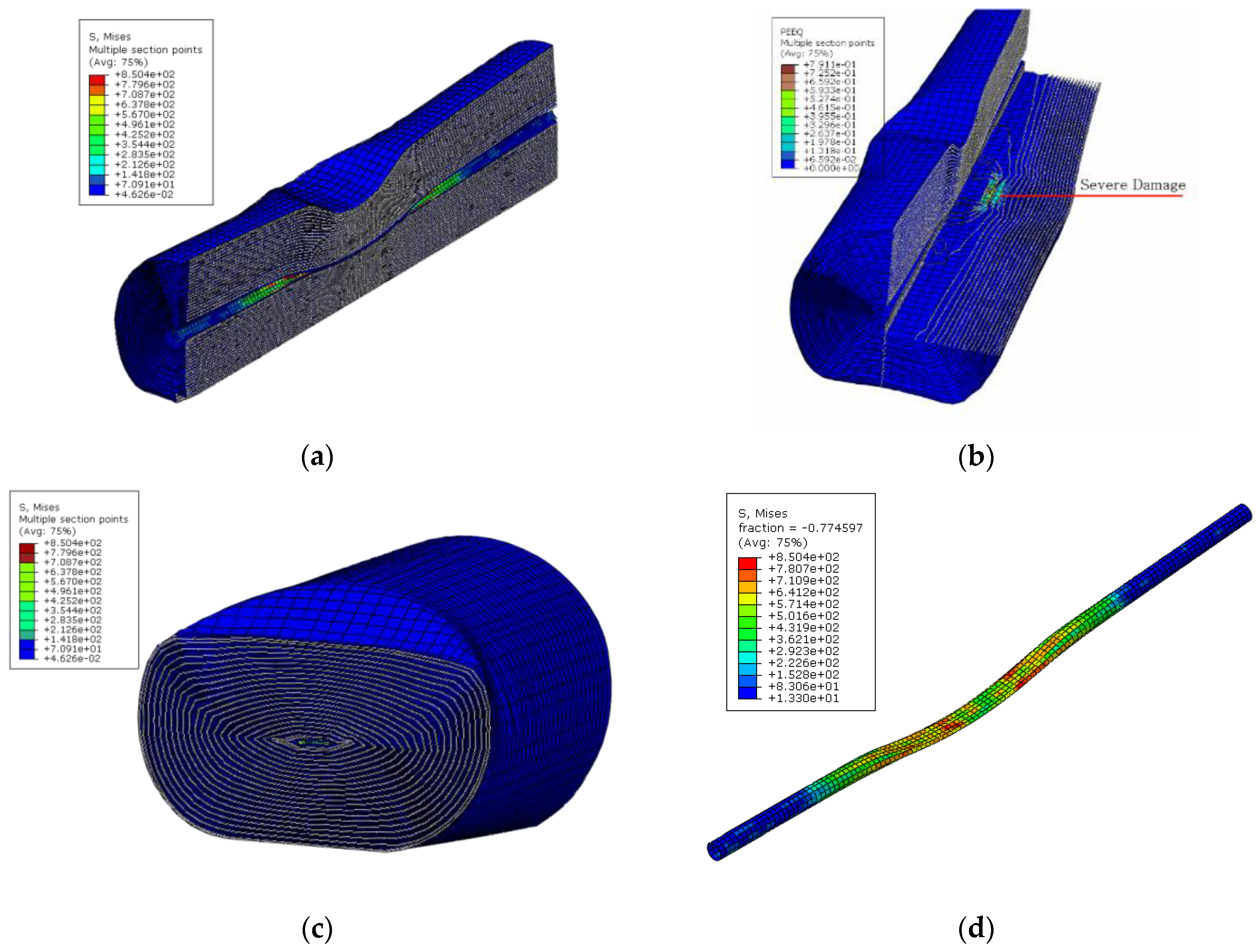
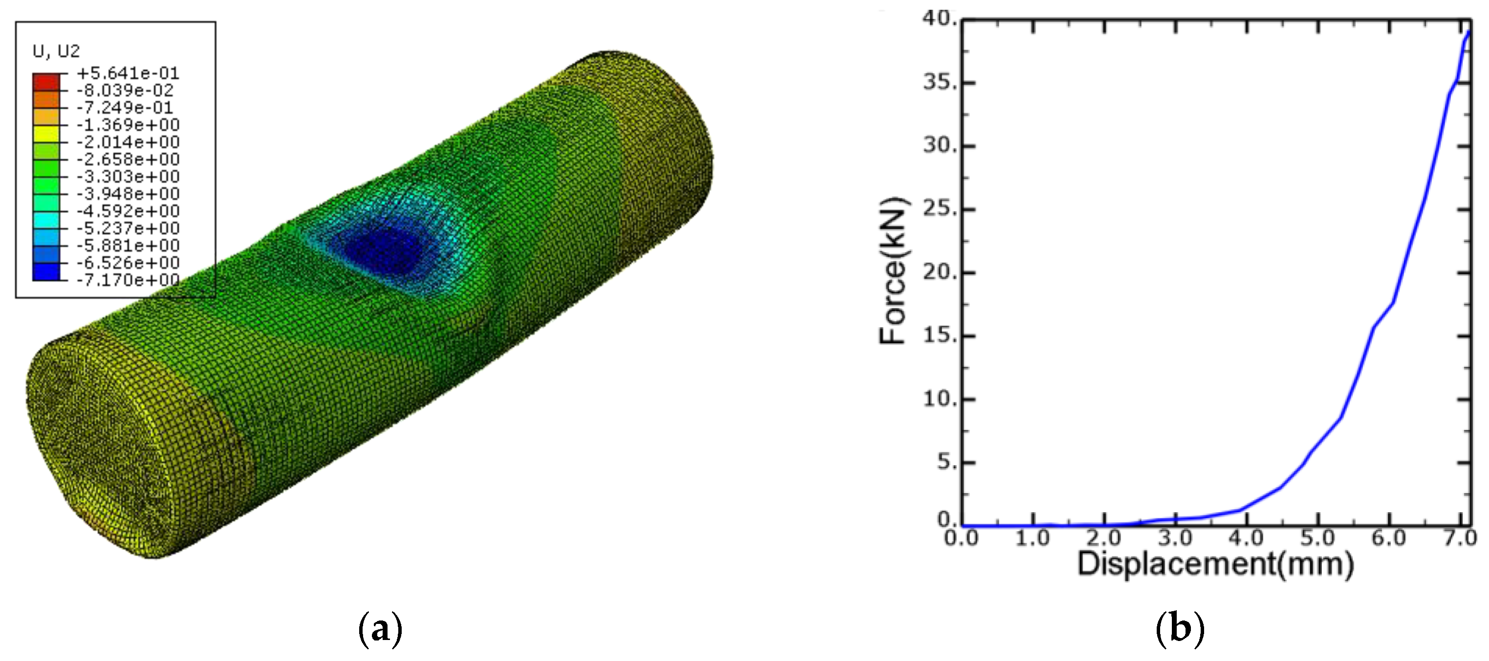
3. Results
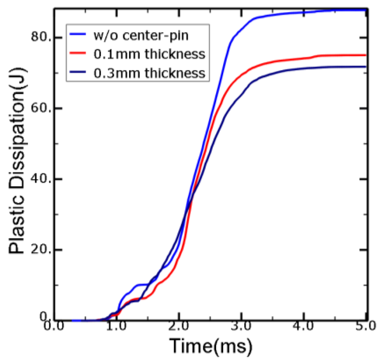
4. Discussion
5. Conclusions
Author Contributions
Funding
Institutional Review Board Statement
Informed Consent Statement
Data Availability Statement
Conflicts of Interest
References
- George, B. The Development and Future of Lithium Ion Batteries. J. Electrochem. Soc. 2017, 164, A5019–A5025. [Google Scholar]
- Zwicker, M.F.R.; Moghadam, M.; Zhang, W.; Nielsen, C.V. Automotive battery pack manufacturing-a review of battery to tab joining. J. Adv. Join. Process. 2020, 1, 100017. [Google Scholar] [CrossRef]
- Löbberding, H.; Wessel, S.; Offermanns, C.; Kehrer, M.; Rother, J.; Heimes, H.; Kampker, A. From Cell to Battery System in BEVs: Analysis of System Packing Efficiency and cell Types. World Electr. Veh. J. 2020, 11, 77. [Google Scholar] [CrossRef]
- Spotnitz, R.; Franklin, J. Abuse behavior of high-power, lithium-ion cells. J. Power Sources 2003, 113, 81–100. [Google Scholar] [CrossRef]
- Feng, X.; Ouyang, M.; Liu, L.; Xia, Y.; He, X. Thermal runaway mechanism of lithium ion battery for electric vehicles: A review. Energy Storage Mater. 2018, 10, 246–267. [Google Scholar] [CrossRef]
- Zhu, J.; Wierzbicki, T.; Li, W. A review of safety-focused mechanical modeling of commercial lithium-ion batteries. J. Power Sources 2018, 378, 153–168. [Google Scholar] [CrossRef]
- Zhang, J.; Zhang, L.; Sun, F.; Wang, Z. An Overview on Thermal Safety Issues of Lithium-ion Batteries for Electric Vehicle Application. IEEE Access 2018, 6, 23848–23863. [Google Scholar] [CrossRef]
- Chen, Y.; Kang, Y.; Zhao, Y.; Wang, L.; Liu, J.; Li, Y.; Liang, Z.; He, X.; Li, X.; Tavajohi, N.; et al. A review of lithium-ion battery safety concerns: The issues, strategies, and testing standards. J. Energy Chem. 2021, 59, 83–99. [Google Scholar] [CrossRef]
- Ruiz, V.; Pfrang, A.; Kriston, A.; Omar, N.; Van den Bossche, P.; Boon-rett, L. Thermal runaway mechanism of lithium ion battery for electric vehicles: A review. Renew. Sustain. Energy. Rev. 2018, 81, 1427–1452. [Google Scholar] [CrossRef]
- Aalund, R.; Pecht, M. The Use of UL 1642 Impact Testing for Li-ion Pouch Cells. IEEE Access 2019, 7, 176706–176711. [Google Scholar] [CrossRef]
- UL 1642; UL Standard for Safety Lithium Batteries. 6th ed. Underwriters Laboratories Inc.: Northbrook, IL, USA, 29 September 2020.
- Kim, S.; Lee, Y.S.; Lee, H.S.; Jin, H.L. A Study on the behavior of a cylindrical type Li-ion secondary battery under abnormal conditions. Mater. Sci. Eng. Technol. 2010, 41, 378–385. [Google Scholar]
- Sahraei, E.; Campbell, J.; Wierzbicki, T. Modeling and short circuit detection of 18,650 Li-ion cells under mechanical abuse conditions. J. Power Sources 2012, 220, 360–372. [Google Scholar] [CrossRef]
- Wierzbicki, T.; Sahraei, E. Homogenized mechanical properties for the jellyroll of cylindrical Lithium-ion cells. J. Power Sources 2013, 241, 467–476. [Google Scholar] [CrossRef]
- Avdeev, I.; Martinsen, M.; Francis, A. Rate and temperature dependent material behavior of a multilayer polymer battery separator. J. Mater. Eng. Perform. 2014, 23, 315–325. [Google Scholar] [CrossRef]
- Liu, P.; Sherman, E.; Jacobsen, A. Design and fabrication of multifunctional structural batteries. J. Power Sources 2009, 189, 646–650. [Google Scholar] [CrossRef]
- Zhao, W.; Luo, G.; Wang, C.Y. Modeling Internal Shorting Process in Large-Format Li-Ion Cells. J. Electrochem. Soc. 2015, 162, A1352–A1364. [Google Scholar] [CrossRef] [Green Version]


| Parts | Elastic Modulus (GPa) | Poisson’s Ratio | Density (kg/m3) | Yield Strength (MPa) |
|---|---|---|---|---|
| Can (SPCE) | 172 | 0.28 | 7860.0 | 256 |
| Cathode (Al foil) | 69 | 0.34 | 2730.0 | 165 |
| Anode (Cu foil) | 110 | 0.36 | 8960.0 | 333 |
| Separator (PE film) | 1.017 | 0.33 | 921.0 | 39.4 |
| Center-pin | 193 | 0.25 | 7960.0 | 515 |
| Parts | von Mises Stress (MPa) |
|---|---|
| Can | 416 |
| Cathode | 16.4 |
| Anode | 10.5 |
| Separator | 157 |
| Center-pin | 860 |
Publisher’s Note: MDPI stays neutral with regard to jurisdictional claims in published maps and institutional affiliations. |
© 2022 by the authors. Licensee MDPI, Basel, Switzerland. This article is an open access article distributed under the terms and conditions of the Creative Commons Attribution (CC BY) license (https://creativecommons.org/licenses/by/4.0/).
Share and Cite
Ahn, Y.J.; Lee, Y.-S.; Cho, J.-R. Multi-Layered Numerical Model Development of a Standard Cylindrical Lithium-Ion Battery for the Impact Test. Energies 2022, 15, 2509. https://doi.org/10.3390/en15072509
Ahn YJ, Lee Y-S, Cho J-R. Multi-Layered Numerical Model Development of a Standard Cylindrical Lithium-Ion Battery for the Impact Test. Energies. 2022; 15(7):2509. https://doi.org/10.3390/en15072509
Chicago/Turabian StyleAhn, Young Ju, Yeon-Seung Lee, and Jin-Rae Cho. 2022. "Multi-Layered Numerical Model Development of a Standard Cylindrical Lithium-Ion Battery for the Impact Test" Energies 15, no. 7: 2509. https://doi.org/10.3390/en15072509
APA StyleAhn, Y. J., Lee, Y.-S., & Cho, J.-R. (2022). Multi-Layered Numerical Model Development of a Standard Cylindrical Lithium-Ion Battery for the Impact Test. Energies, 15(7), 2509. https://doi.org/10.3390/en15072509