Review

Design Evaluation of a Next-Generation High-Temperature Particle Receiver for Concentrating Solar Thermal Applications

Sandia National Laboratories, Albuquerque, NM 87185, USA
*
Author to whom correspondence should be addressed.
Energies 2022, 15(5), 1657; https://doi.org/10.3390/en15051657
Submission received: 31 December 2021 / Revised: 2 February 2022 / Accepted: 7 February 2022 / Published: 23 February 2022

Abstract

:
High-temperature particle receivers are being developed to achieve temperatures in excess of 700 °C for advanced power cycles and solar thermochemical processes. This paper describes designs and features of a falling particle receiver system that has been evaluated and tested at the National Solar Thermal Test Facility at Sandia National Laboratories. These advanced designs are intended to reduce heat losses and increase the thermal efficiency. Novel features include aperture covers, active air flow, particle flow obstructions, and optimized receiver shapes that minimize advective heat losses, increase particle curtain opacity and uniformity, and reduce cavity wall temperatures. Control systems are implemented in recent on-sun tests to maintain a desired particle outlet temperature using an automated closed-loop proportional–integral–derivative controller. These tests demonstrate the ability to achieve and maintain particle outlet temperatures approaching 800 °C with efficiencies between 60 and 90%, depending on incident power, mass flow, and environmental conditions. Lessons learned regarding the testing of design features and overall receiver operation are also presented.

1. Introduction

Concentrating solar power (CSP) systems utilizing particle technology is a burgeoning field with the capability to achieve levelized cost of electricity (LCOE) targets proposed by the Department of Energy Solar Energy Technology Office of 5¢/kWhe [1]. In particle-based CSP systems, solid particles are used as a heat transfer medium to enable temperatures in excess of 700 °C necessary to couple with high-efficiency power cycles (e.g., supercritical-CO2 (sCO2) cycles). In such systems, thermal-to-electric efficiencies exceeding 50% can be realized to support achieving LCOE targets for next-generation systems [2]. Traditional heat transfer mediums of molten nitrate salts or steam in existing CSP plants with turbine inlet temperatures limited to <600 °C typically operate at lower thermal-to-electric cycle efficiencies between 30% and 40% [3].
Particles present a number of other advantages over traditional working fluids for CSP including efficient sensible energy storage, low parasitics in gravity driven systems, low costs for a heat transfer medium, capability for direct irradiation eliminating the flux limitations of tubular receivers, the experimentally demonstrated ability to reach temperatures >800 °C [4,5], and the absence of trace heating to prevent freezing needed for molten salt systems. Early research in particle-based CSP systems at Sandia National Laboratories (SNL) dates back as far as the 1980s [6,7,8,9,10], and a resurgence in the concept for next-generation CSP energy generation and solar thermochemical processes has occurred in the last decade or so because of many of the benefits listed above [3,11,12,13].
To enable this technology, maximizing the thermal performance of the particle receiver is essential. Specifically, the thermal efficiency of the receiver, defined as the fraction of the incoming radiative energy absorbed by the particles, is a critical parameter in the LCOE. Values as high as 90% are being targeted for next-generation systems [3,14], but some system-level analyses have shown that receiver efficiencies below 90% may still be able to achieve an LCOE < 6¢/kWhe [15,16]. Research into particle receivers has been a high priority in the CSP community, and a significant number of technological advances have been made. A number of different receiver designs are proposed in the literature for particle-based CSP systems. These designs largely fall within three categories: falling particle receivers (FPRs) and its variants [11,17,18,19], centrifugal receivers [5,20,21,22,23], and fluidized bed receivers [13,24,25,26]. Each of these concepts has potential in future systems. However, this paper focuses on the latest research and developments of the FPR concept developed and tested at the National Solar Thermal Test Faculty (NSTTF) at SNL. Specifically, this paper summarizes the most relevant experimental and numerical studies performed at the NSTTF in order to inform the broader solar energy community on the recent conclusions and recommendations for similar particle-based CSP systems.
The FPR concept consists of dropping a curtain of particles within a cavity that intercepts a beam of concentrated sunlight via gravity. Advantages of FPRs include direct irradiance of the heat transfer medium (i.e., particles), experimental evidence of achieving high outlet temperatures [4,27], low parasitics, and being conceptually simple and inexpensive (whereas traditional receivers often consist of very expensive components [28]). A number of variations of this concept have been investigated including strictly north-facing cavities [29], face-down cavities [30,31,32], and recirculating cavities [30,32]. Furthermore, in addition to purely free-falling FPRs, various particle obstructions have been investigated to slow the particle descent through the cavity using either meshes [17,33,34] or discrete ‘catch-and-release’ troughs [4,18,35] (as will also be discussed later in this paper). Novel particle curtain patterns to leverage light-trapping and volumetric heating effects have also been investigated though the benefit to the thermal performance has been outweighed by other considerations [36,37,38].
Cavity-type receivers are used to minimize the impacts from wind [28] and convective heat transfer from the particle curtain while still enabling direct irradiation of the particles. However, despite being in a cavity, wind may still have a significant impact on the thermal efficiency and particle loss [39,40,41]. While cavity receivers for CSP systems is far from a new concept [28], additional considerations for cavity receivers include accounting for the entrained flow created by the falling particles (and the interaction with wind), minimizing wall erosion from particle contact, minimizing particle attrition, and minimizing particle loss through the cavity aperture. The particle size lost from FPRs varies from the nominal particle diameter (typically 300–700 μm in diameter) down to abraded particle dust (≤1 μm in diameter) though sampling of particles from the tests suggests that the concentrations are within acceptable health standards [42].
Recent advances in particle technology for CSP at SNL have motivated an award to construct a 1 MWth particle-based CSP facility called the Generation 3 Particle Pilot Plant (G3P3-USA (G3P3-USA to differentiate it from its sister facility, G3P3-KSA, to be built in Saudi Arabia)) at the NSTTF in Albuquerque, NM [43]. Much of the following research presented in this paper directly informs the final G3P3-USA FPR design. This includes a number of features and operational strategies to augment a traditional FPR concept to minimize heat losses and maximize the thermal efficiency. However, some of the features discussed in this paper are not adopted in the final design as they are not found to be effective in all conditions or showed a lack scalability for commercial FPRs with significantly larger cavities and apertures.
Analysis of early test campaigns featuring a FPR system at the NSTTF [27] indicated that low thermal efficiencies could be explained by advective heat loss through the open cavity aperture [44]. Furthermore, minimizing this loss mechanism could yield very high receiver thermal efficiencies [41]. As has been utilized in solar reactors to control the ambient environment [45], quartz aperture covers are explored experimentally and numerically to obstruct or reduce hot air flow escaping from the cavity aperture while still remaining transmissive to the incoming solar radiation. Likewise, forced air curtains, or aerowindows, are also explored to control the air exchange out of the open aperture subject to varying environmental conditions building upon previous research in this area [39].
Variations on the FPR concept include the use of particle flow obstructions placed in the path of the particle curtain to slow the descent and increase the residence time of particles within the concentrated solar beam. These variations are often referred to as multistage or obstructed flow receivers. Early research into chevron wire meshes has been tested experimentally at the NSTTF though early versions of the concept suffered damage during operation [46]. Discrete “catch-and-release” troughs [18,35] are another multistage concept that is explored numerically and experimentally at the NSTTF. These troughs are designed to minimize surfaces directly exposed to the incident radiation, thereby minimizing damage to the structures, while still slowing the particles’ descent.
As discussed above, cavity-type receivers have been studied extensively to maximize the overall receiver efficiency subject to a number of different environmental conditions [47,48] though the presence of a falling particle curtain precludes applying many lessons learned for FPRs. Therefore, an extensive cavity optimization is necessary to consider additional particle effects and ensure that advective losses from the cavity are inherently minimized. The use of converging tunnels or shrouds around the cavity aperture are also investigated in this optimization and with other design features that may act to concentrate radiative flux entering the cavity and minimize the effect of wind.
In addition to different features aimed at improving the thermal efficiency, a necessary component in the operation of FPRs is the ability to control the particle outlet temperature. For the existing FPR tested at the NSTTF, a linearly actuated slide gate has been used to control the particle curtain mass flow rate entering the cavity [27]. This enables control of the particle outlet temperature since the temperature increase is inversely proportional to the particle mass flow rate during operation. In situ measurements of the particle temperature integrated with a proportional control algorithm to adjust the particle mass flow rate accordingly have been tested [27]. More sophisticated proportional–integral–derivative (PID) control algorithms are still needed to minimize an oscillating response in the particle outlet temperature.
The remainder of this paper is organized as follows. First, a description of the NSTTF experimental capabilities and numerical methods that have been leveraged to study different FPR features is included. Then, recent experimental and numerical studies on each of the features or control strategies are summarized including quartz-aperture covers, active air flow, multistage features, cavity/shroud optimization, and PID control of the particle outlet temperature. Finally, the conclusions of each of these studies are used to inform the final G3P3-USA FPR design and make future recommendations about the path forward for FPRs in next-generation CSP systems.

2. Experimental and Numerical Methods

The FPR features and control strategies discussed in this manuscript are analyzed using a combination of experimental and numerical analysis. The following section describes the experimental facilities, tests, and numerical methods applied to assess the viability of each topic in the cited studies.

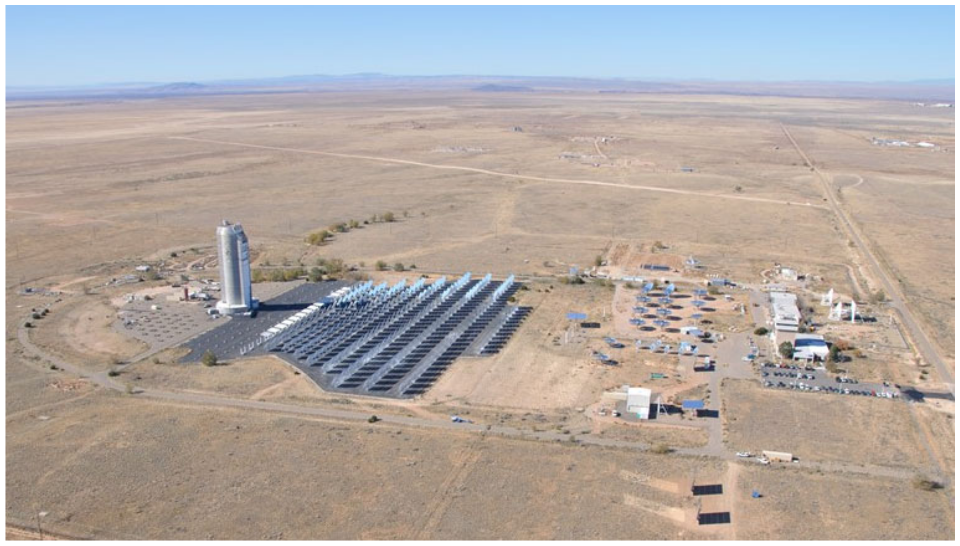
2.1. National Solar Thermal Test Facilty

Sandia National Laboratories operates the National Solar Thermal Test Facility (NSTTF), a large-scale multipurpose research and test facility for concentrating solar thermal technologies. The NSTTF includes a 6 MWth central receiver test facility with over 200 heliostats, a 1 MWth FPR system, a 16 kWth solar furnace, a high-flux solar simulator with robotic arm for automated accelerated aging tests, a molten salt test loop, a particle-based heat-exchanger test rig with sCO2 test loop, a rotating platform, and other facilities and equipment for testing CSP components and systems (Figure 1). For over 40 years, Sandia has been leading R&D in solar thermal energy technologies, including research in power production, thermal energy storage, process heat, thermochemistry, and solar fuels. High-performance computing resources are also available for detailed computational fluid dynamics modeling of complex, coupled processes associated with CSP.

2.2. NSTTF Falling Particle Receiver System

The 1 MWth FPR system at the NSTTF [4,27,46] is elevated from ground level to the top of the existing 200 ft solar tower for on-sun testing as shown in Figure 2. The system is composed of a particle feed hopper, a linearly-actuated slide gate to control particles from the hopper, a 1 MWth FPR cavity with a ~1 m2 square aperture, a bottom collection hopper, an auger-type “Olds” particle elevator to return particles to the feed hopper, a liquid-cooled flux calibration panel, and ducting to convey the particles between these systems. Particles within the feed hopper are dropped as a curtain through the receiver via a slot created by the slide gate at the top of the cavity and fall via gravity past the beam of concentrated radiation provided by the NSTTF heliostat field. The particles are directly exposed to the concentrated solar flux. The heated particles are collected in the bottom hopper, where they flow to the inlet of the particle elevator. Particles are then lifted back to the top of the system where they are used for subsequent cycles. This prototype FPR system does not include any explicit heat rejection, meaning that the temperature of the particles within the system will continuously rise when on-sun. This results in pseudo steady-state experiments. Sintered bauxite particles with a nominal diameter of ~350 μm are used in recent experiments for their size, durability, radiative properties [3,49,50], and relatively low cost [3].
Instrumentation within the FPR system provides the measurements needed for the calculation of the receiver efficiency as follows:
η r e c = Q a b s Q i n = m ˙ h o u t h i n Q i n = m ˙ T i n T o u t c p T d T Q i n
where Q a b s is the thermal power absorbed by the particles, Q i n is the radiative power entering the cavity through the aperture, h is the particle enthalpy, m ˙ is the particle mass flow rate, and c p T is the particle specific heat as a function of the particle temperature, T . To measure the particle inlet temperature, five thermocouples (TCs) are positioned in the particle pile just above the slide gate opening and appropriately averaged. The receiver outlet temperature is measured with five additional TCs located in specially designed funnels positioned along the curtain’s width near the bottom of the receiver. The funnels are designed to ensure that the TCs remain immersed in particles during operation while minimizing lag in the measurement. This concept has been used for decades [51]. The particle mass flow rate entering the cavity is controlled by varying the slot opening created by the slide gate and is measured by the change in mass measured from load cells on the feed hopper over time when the particle elevator is temporarily turned off. Early experimental setups [27] used a separate “weigh hopper” below the FPR instead of the feed hopper to measure the particle mass flow rate (c.f. Figure 2).
The radiative power entering the FPR aperture is measured using an adjacent water-cooled flux calibration panel with a diffuse surface. A beam of concentrated flux is positioned on the panel, and a Kendall cavity-type radiometer measures a discrete flux value of that beam near the peak flux. An optical camera and beam characterization software then measures the intensity of light reflected from the panel and correlates the pixel intensity to the flux measured by the radiometer. This provides the spatial radiative flux distribution which is used to calculate the radiative power that is entering the FPR aperture [52]. This measurement is taken periodically during operation of the receiver throughout the day.

2.3. Modeling and Simulation Strategy

Advanced numerical models of FPRs typically require the inclusion of a wide array of different physics to predict the radiation, fluid, particle, and energy transport that occurs. The inclusion of all these physical models and the complex interactions between them is often necessary to predict a FPR’s thermal efficiency subject to different environmental conditions. For the numerical analysis summarized in the following sections, a Lagrangian/Eulerian formulation coupled with a discrete ordinates (DO) radiation model (Lagrangian/Eulerian/DO model for short) is leveraged. Monte Carlo radiation models could be used [53] though the relatively low computational expense and historical prevalence DO models [38,54,55] makes it the primary choice herein. Other modeling efforts have treated the falling particle curtain as a continuum [56,57] (often referred to as a two-fluid or Eulerian/Eulerian model), though the low particle volume fractions that occur within FPRs (generally < 10% for smaller FPRs [55,58,59]) ensures that particle collisions may generally be neglected and a simple Lagrangian model may be used. The ANSYS Fluent® software suite is primarily utilized for these models to take advantage of the broad multiphysics capabilities the software offers.
The complete equation set is too extensive to include in its entirety; however, the primary equations and assumptions are summarized here. A steady-state formulation is presented as it constitutes the majority of the numerical analysis that is discussed. The steady, Reynolds-averaged Navier–Stokes (RANS) equations are used to model the turbulent air continuum:
ρ u i x i = 0
ρ u i u j x j = p x i + x j μ u i x j + u j x i 2 3 δ i j u I x I + ρ g i + F i + x j ρ u i u j ¯
where ρ is the air density, u i is the time-averaged air velocity vector, μ is the air viscosity, p is the pressure, g i is the gravity vector, F i are the external body forces, and ρ u i u j ¯ are the Reynolds stresses. The realizable k ε turbulence model [60] is used to close the RANS equations where the transport equations for the turbulent kinetic energy k and turbulent dissipation ε are omitted for brevity. Typically, Fluent’s scalable wall functions or enhanced wall functions [61] are applied to model the turbulence near the walls which provides a degree of mesh independence in the wall boundary layers for mass and heat transport. The energy transport in the fluid is modeled as:
x i ρ u i h + u 2 2 = x i k e f f T x i + S  
where h is the enthalpy of the air, T is the air temperature, S is the energy source term, k e f f = k a + c p μ t / P r t is the effective thermal conductivity for the realizable k ε model, k a is the air thermal conductivity, c p is the air specific heat at constant pressure, μ t is the turbulent viscosity, and P r t = 0.85 is the turbulent Prandtl number. The properties of the air are temperature dependent. The heat equation is applied to model energy transport through the solid insulative walls of the FPR cavity as follows:
x i k s T s x i = 0
where k s is the solid thermal conductivity and often a function of temperature.
Particles are modeled in parcels where each simulated particle is representative of thousands of physical particles with diameters O (100 μm). The equation of motion for each particle parcel in a Lagrangian reference frame is:
m p 18 μ ρ p d p 2 C D R e 24 u i u i , p + m p g i ρ p ρ ρ p = 0
where m p is the particle parcel mass, u i , p is the particle parcel velocity vector, u i is the fluid velocity vector, ρ p is the particle density, ρ is the fluid density, d p is the particle diameter, C D is the coefficient of drag, and R e = ρ d p u i , p u i / μ is the relative Reynolds number. All particles are assumed to be spherical and C D is a function of R e based on correlations from Morsi and Alexander [62]. The particle temperature is modeled as:
h c A p T T p + ε p A p σ θ R 4 T p 4 = 0
where h c is the convective heat transfer coefficient using the Ranz–Marshall correlation [63], A p is the particle surface area, ε p is the particle emissivity, σ is the Stefan–Boltzmann constant, T p is the particle temperature, and θ R is the radiation temperature defined as:
θ R = G 4 σ 1 / 4 w h e r e G = Ω = 4 π I d Ω
where G is the incident radiation, I is the radiation intensity, and Ω is the solid angle. The source terms (momentum and energy) in each cell from the particle’s velocity and temperature are updated between each non-linear iteration of the continuum equations. Particles are injected into the domain at hundreds of discrete points corresponding to the particle curtain location within the cavity.
Radiative heat transfer in the continuum is modeled with a non-gray DO model using the grey-band radiative transport equation for different wavelength bands:
s i I λ s x i + α λ + σ s I λ s = α λ I b λ + σ s 4 π G
where I λ is the radiation intensity for band λ , α λ is the spectral absorption coefficient, σ s is the scattering coefficient, and I b λ is the black body intensity given by the Planck function. Three spectral bands are typically used in the radiation models 0–2.5, 2.5–4.5, and 4.5–100 µm, where the 2.5 µm delineation reasonably separates the solar spectrum from the thermal spectrum. An additional delineation occurs at 4.5 µm to accommodate varying radiative properties of the insulative boards comprising the FPR cavity walls. The air continuum is assumed to not affect the radiation transport.
The air continuum is modeled inside and outside the FPR cavity to ensure that the buoyant flow through the aperture is captured. This also enables specifying various wind conditions to be simulated on the external boundaries of the domain as velocity boundary conditions. Pressure boundaries are applied for the downstream wind external surfaces or for external surfaces without wind. Particles escape the domain through the external boundaries and the FPR bottom hopper outlet. Otherwise, particles rebound with a coefficient of restitution defined by the wall material.
Concentrated radiation from the heliostat field is applied as a radiative boundary condition on the north external boundary (all cavities are assumed to be north-facing in the following studies) within the solar wavelength band. Radiation is either defined as a simple, approximated uniform beam with representative directionality from the heliostats [64] or through a series of analytical functions fit to ray-tracing results [65] using either NREL’s SolTrace [66] or SolarPILOT [67]. The analytical functions describe the spatially varying intensity, directionality, and spread of the beam emanating from each cell face on the north surface.
Unstructured tetrahedral meshes are used to accommodate complex geometrical features and rapid meshing. Mesh convergence studies have been performed for FPRs at various scales [41,44,55,68], suggesting that meshes > ~1 × 10⁶ elements are sufficient to ensure that errors from the spatial discretizations are negligible on the conclusions.

3. Falling Particle Receiver Studies

Recent studies on the efficacy of various FPR features and control strategies are discussed below including studies for quartz half-shell aperture covers, active air control, multistage features, receiver cavity optimization, and the PID control of the particle outlet temperature.

3.1. Quartz Half-Shell Aperture Covers

Quartz aperture covers were investigated as a means to reduce convective heat loss from open-aperture FPR cavities. Quartz is an ideal material due to its high transmissivity in the solar spectrum (<2.5 microns) and low transmissivity in the near infrared spectra [69], enabling concentrated sunlight to pass through the aperture to the particles while trapping heat within the receiver. Yellowhair and Ho [70] performed ray-tracing analyses on the 1 MWth NSTTF FPR to evaluate different configurations of apertures covered with quartz half-shells (glass tubes cut in half lengthwise similar to other designs in the literature [71]). A shroud (or hood) was investigated as a means to support the half-shells at a desirable angle relative to the incoming flux while also potentially mitigating adverse impacts from wind. Figure 3 shows an example of configurations that were investigated.
Ray-tracing simulations using NREL’s SolTrace of the incident irradiation on the falling particles from the heliostat field at the NSTTF showed that the use of quartz half-shell covers reduced the irradiance on the particles due to reflection from the quartz by up to 7%, depending on the spacing between the half-shells. However, the integrated shroud/hood increased the net irradiance entering the receiver by up to 9%, acting as a secondary concentrator when the diffuse reflectance was assumed to be 0.9 (unsoiled white paint). The direction of the curved side of the quartz half-shells (i.e., convex side facing in or out) did not have a significant impact on the simulated results.
Supplementary numerical simulations on a slice of the FPR cavity described above were performed by Yue et al. [64,72] using Lagrangian/Eulerian/DO models (a slice of the receiver cavity was used to limit the computational expense). These simulations enabled evaluating the temperature of the quartz and the thermal efficiency of the FPR for quartz half-shells either fully covering or partially covering the aperture compared to an uncovered aperture with shroud (Figure 3b). Results showed that very high quartz transmissivities in the solar spectrum (>0.95) were necessary to minimize the quartz temperature and overcome additional thermal losses created by convection from the quartz itself in a fully covered aperture. Otherwise, the relative improvement in thermal efficiency over an uncovered aperture was minimal.
Experiments were performed using a single quartz half-shell exposed to different concentrated solar fluxes with the convex side facing toward or away from the heliostat field [64]. Results showed that average total transmissivities were 0.97 ± 0.01 and 0.94 ± 0.02 for the concave and convex side towards the heliostat field, respectively. Thus, orienting the concave side of the quartz half-shell toward the incident radiation did result in an increase in total transmission, likely as a result of additional light trapping relative to the orientation with the convex side toward the incident radiation. These results also suggest that pristine quartz may have sufficient transmissivity for FPR aperture covers based on the numerical simulations described above.

3.2. Active Air Flow

Similar to aperture covers, active air flow may act as a method to control advective losses from the FPR subject to varying environmental conditions (e.g., wind) in lieu of a physical barrier. Recent numerical studies using a Lagrangian/Eulerian/DO model on the effect of air suction from within the cavity and forced air flow across the aperture, also called an aerowindow, for the 1 MWth NSTTF FPR were performed by Yue et al. [73]. Different air suction locations within the cavity were considered, and aerowindows originating from the top and bottom of the aperture were simulated under various wind conditions as shown in Figure 4a. Only modest improvements in the thermal efficiency were observed for air suction near the bottom aperture where other suction locations were outweighed by the additional thermal losses created by removing hot air from the cavity. Recirculation of the removed hot air back into the cavity was not investigated.
A significant reduction in the advective losses was observed for an aerowindow at the bottom of the aperture at 9 m/s and 115° (c.f. Figure 4a) in quiescent conditions. Advective losses decreased from 187 kW nominally to 27 kW subject to an incident radiative power of 890 kW. In this case, the aerowindow impinged on the integrated cavity hood (shroud) and redirected a large fraction of hot air back into the cavity that would otherwise escape. However, similar to Tan et al. [39], the improvements in the thermal performance were limited to lower wind speeds and only a range of wind directions as indicated in Figure 4b. At the very highest wind speeds up to 15 m/s, the aerowindow was overwhelmed and performed poorly. Ultimately, a single aerowindow configuration was not found that minimized the advective losses in all conditions.

3.3. Staggered Angle Iron Receiver (Multistage)

A multistage FPR concept consisting of staggered troughs or angle irons (i.e., a staggered angle iron receiver (StAIR)) was experimentally investigated to improve curtain uniformity, increase particle residence time, and increase the curtain opacity. The troughs in the StAIR design, similar to other catch-and-release designs [18,35], are structures that collect and discharge particles over the trough’s leading edge reducing particle velocity (and therefore increasing the curtain opacity) through the cavity as shown in Figure 5a. Particles spilling over the leading edge of the trough toward the receiver aperture prevents direct exposure of the trough surfaces to the beam. In addition, particles impacting the stagnant particles in each trough prevents any erosion of the trough surfaces from abrasion.
Tests were conducted using a cold-flow (unheated) test rig to determine the effect of the trough geometry, the curtain impingement location, the orientation, and the vertical distance from the curtain origin on curtain opacity at linear mass flow rates between 2 and 14 kg/m/s [74]. The curtain opacity 30 cm below the stair structures was compared to the opacity of a free-falling curtain at the same location. Four geometries were tested as shown in Figure 5b. The “hybrid trough” consisting of a sloped back, flat bottom, and vertical front lip resulted in a 25% increase in curtain opacity over a free-falling curtain while maintaining a large catchment area necessary for scaling to larger FPR systems. The opacity of curtains at lower particle mass flow rates was also found to be more sensitive than higher mass flow rates due to effects outlined by Ho et al. [58]. For particle mass flow rates of 3–6 kg/m/s, troughs were found to increase the particle curtain opacity when placed 30–90 cm below curtain origin.
The StAIR concept was also tested on-sun using up to two hybrid troughs retrofitted into the existing 1 MWth FPR at the NSTTF [75]. Cold flow testing within the receiver prior to on-sun testing showed improved curtain uniformity compared to free-fall. Large temperature gradients in early testing warped elements of the slide gate which reduced curtain uniformity as shown in Figure 6a. However, this curtain behavior was corrected with the multistage design (Figure 6b) providing the receiver back wall with more consistent shading and protection from the incident solar flux.
Lagrangian/Eulerian/DO models of the StAIR design were used evaluate the thermal performance for different numbers of troughs and particle mass flow rates [76]. However, reduced order models for the interaction between the falling curtain and the troughs were necessary to account for the complex physics. For the reduced order models, the stagnant particles within each trough was modeled as a solid and falling particle collisions with the stagnant particle were modeled using fixed rebound velocity of 0.3 m/s that closely approximated the observed curtain behavior from cold flow experiments [74] (c.f. Figure 5a vs. Figure 7a). Although the particle curtain trajectory was not accurately captured, the heat transfer to and from the particles was minimally affected for similar residence times in the cavity.
Using the models, the thermal losses from various loss mechanisms were computed for zero, two, and four troughs in the cavity at two different particle mass flow rates as shown in Figure 7b. Radiative losses from the cavity were found to decrease slightly with an increasing number of troughs despite increasing particle volume fractions indicative of diminishing returns at this scale. Advective losses also decreased from the cavity with an increasing number of troughs primarily as a consequence of altering the airflow within the receiver that inhibited ingress of cooler ambient air. Although radiative losses were not significantly decreased, a multistage release did show significantly decreased back wall temperatures of up to 200 °C, enabling a wider range of operating conditions. These lower temperatures were also observed in simulations of the early G3P3-USA FPR featuring hybrid troughs in Mills et al. [65].

3.4. Falling Particle Receiver Cavity Optimization

A receiver cavity optimization was performed in Mills et al. [77] on a 1 to 2 MWth FPR using Lagrangian/Eulerian models (i.e., without a radiation model) to find a suitable cavity shape that minimized advective losses from the receiver nominally. A converging tunnel leading to the cavity from the tower’s front surface (similar to the hood/shroud discussed above) was integrated in the optimization (referred to as a solar nod optimized unobstructing tunnel; SNOUT for short). Recall that design guidance exists for cavity-type CSP receivers [28]; however, the inclusion of a falling particle curtain introduces additional considerations [59] to the design. Using a Latin hypercube sampling technique, 12 geometric parameters of the cavity were varied generating a total of 320 realizations of the receiver. From the computed sensitives of each geometric parameter (summarized as Sobol indices in Figure 8a) and the best performing realization, a suitable receiver geometry was identified and simulated using a Lagrangian/Eulerian/DO model to yield a receiver thermal efficiency up to 86.9% with advective losses of only 3.4%. The high thermal efficiencies observed in optimized cavity occurred from a significant reduction in the advective losses. Advective losses of ~10–25% of the incident thermal power were observed for the previous NSTTF FPR [44]. Figure 8b shows the velocity field inside the cavity colored by air temperature where a large fraction of the hot buoyant flow is redirected back into the cavity. Further optimization of the cavity and parametric studies subject to various determinantal wind conditions in Mills et al. [65] continued to show receiver efficiencies exceeding 80%.
The final receiver cavity from this optimization was referred to as a reduced volume receiver (RVR) as a result of the reduction in cavity volume over the NSTTF FPR. Mills et al. [65] also explored an integrated ‘chimney’ into the SNOUT to recapture advective losses and fine particulate escaping from the cavity that takes advantage of the inherent velocity field depicted in Figure 8b. Lagrangian/Eulerian/DO models showed that a large fraction of particle fines < 10 μm in diameter were captured by the chimney and could be removed by additional filtration methods [78].

3.5. PID Particle Outlet Temperature Control

Operation of a FPR in practice requires control of the particle outlet temperature to ensure the temperature delivered to downstream components is within acceptable tolerances. Environmental conditions such as wind, clouds, or variations in the direct normal irradiance (DNI) can change the net power absorbed by the particles within the receiver. At the NSTTF FPR, the outlet temperature is controlled by varying the particle mass flow rate entering the cavity using a linearly actuated slide gate controlled through feedback from the particle temperature [27]. The particle mass flow rate is inversely proportional to the particle temperature. For example, if the outlet temperature is too high, the slide gate opens and increases the mass flow rate such that the particle temperature is decreased and vice versa. An advantage of this approach is that it responds equivalently to changes in DNI or wind though the timescales of these perturbations are different.
A proportional–integral–derivative (PID) controller was used to actuate the receiver slide gate to continuously control the mass flow rate through the receiver and maintain the receiver outlet temperature at a given setpoint in recent on-sun tests [75,79]. Previous control strategies with only a proportional control created undesirable oscillations in the outlet temperature [27]. The P, I, and D parameters were tuned manually by observing the over- or under-damped behavior of the system and adjusting the parameters accordingly. Figure 9a illustrates the operation and control of the receiver slide gate for varying desired outlet temperatures on-sun for a 1600 s test. The solid green line ‘A’ and the dashed orange line ‘C’ indicate the measured and desired outlet temperature, respectively. The solid grey line ‘B’ indicates the steadily climbing particle inlet temperature (recall that the NSTTF FPR system lacks explicit heat rejection). The solid blue line ‘D’ represents the receiver slide gate position on a normalized scale, 0 indicating fully closed and 1 indicating fully open. Although there are oscillations in the response, the measured particle outlet temperature adequately tracked the desired setpoint temperature as it evolved through the test.
The PID controller was also evaluated following a ~20% perturbation in the incident radiative power (achieved by removing a portion of the heliostats during operation) [75]. Two standard deviations in the particle outlet temperature was targeted to remain within ±10 °C of the setpoint temperature in the minutes following the perturbation. The response is shown in Figure 9b. After the perturbation from 739 to 610 kW, the PID controller successfully reacted to the disturbance and the receiver outlet temperature quickly recovered within the targeted tolerance.

4. Results and Discussion

4.1. Receiver Features Integrated into G3P3-USA

For the FPR features discussed above, some showed a sufficient increase in the receiver thermal efficiency to be adopted into the 2 MWth G3P3-USA FPR design. The primary reasons for excluding features include an inconsistent benefit in the thermal performance in all environments, excessive complexity in the design, or the uncertainty in the feature’s ability to scale to larger FPR systems. For particle-based CSP plants up to 100 MWe in size, a single FPR cavity aperture requires curtain areas of 500–800 m2 [80]. For such large FPRs, aperture dimensions are expected to be >20 m.
While the quartz half-shells discussed above show higher thermal efficiencies for a fully covered aperture and sufficiently high pristine transmissivities, the manufacturing of a quartz half-shell that could sufficiently cover large apertures is uncertain [64]. The additional complexity of supporting large half-shells over a large span in any environment also presents challenges. Furthermore, while pristine quartz does show some minor improvement for a fully covered aperture, additional systems may be necessary to ensure that excessive soiling does not occur from the deposition of small particulate on the quartz surfaces thus lowering the quartz transmissivity over time. It is primarily for these reasons that quartz-half shells are not integrated in the G3P3-USA FPR.
Active air control, primarily in the form of an aerowindow across the aperture, shows significant improvement to the FPR thermal efficiency in quiescent and low wind speed conditions, but the results are inconsistent for all environmental conditions particularly with the highest wind speeds. Estimates of the anticipated environmental conditions for a FPR annually show that the highest wind speeds do not occur frequently enough to significantly impact the annualized thermal efficiency [81]. However, including an aerowindow also adds additional parasitics and complexity to the FPR design. Like the quartz half-shells, the scalability of the concept up to apertures of 20 m in size is unknown. Apertures of only 1 m2 in size are shown numerically to be overwhelmed by strong winds. While still having potential as a feature for future FPRs, the uncertainty described above precludes incorporating the concept in G3P3-USA.
Other design features, including the optimized FPR cavity with SNOUT and multistage features are adopted in the G3P3-USA FPR. The optimized cavity shows consistently high thermal efficiencies for quiescent conditions [77] and for various wind directions and speeds up to 15 m/s [65]. The integrated chimney in the SNOUT also shows promise for commercial scale FPRs, but the benefits would not be realized by G3P3-USA where fine particulate is removed elsewhere in the system and advective losses would not be recuperated. While the multistage catch-and-release troughs (i.e., StAIR) do not significantly increase the thermal efficiency, other critical benefits include improved curtain behavior and uniformity with decreased back wall temperatures. Small reductions in the radiative losses are observed but the benefit is largely second order at the G3P3-USA scale [76].

4.2. On-Sun NSTTF FPR Testing

The most recent on-sun receiver test campaign concluded in 2021 and was used to evaluate the reduced volume receiver (RVR) concept, multistage features, and the PID outlet temperature control system. In the tests, temperatures as high as 800 °C were achieved with concentrated solar fluxes up to ~1000 kW/m2., and particle mass flow ranged from ~3 to 11 kg/s. Receiver thermal efficiencies were calculated for each pseudo steady-state experiment as defined in Equation (1).
FPR thermal efficiencies as a function of incident power during on-sun tests performed during this test campaign [4] are plotted in Figure 10, along with a theoretical maximum receiver efficiency operating at 650 °C for reference. Results showed that the receiver efficiency tended to increase with increasing incident power, which reduces the relative impact of heat losses. Receiver efficiencies less than ~60% tended to be a result of low irradiance, high temperatures, low particle flow rate (which increases transmittance through the particle curtain), wind, or some combination of those factors.
In tests of the RVR concept on-sun, the existing NSTTF FPR was retrofitted with a cavity truncation that approximated the shape of the optimized geometry. Using repeated experimental conditions from the previous test campaign [27] (with as similar wind conditions as could be achieved), additional tests [75] compared the receiver thermal efficiency with the cavity truncation against the cavity without the truncation as shown in a parity plot in Figure 11. All of the repeated experiments with the cavity truncation are at or above the parity line showing a consistently higher thermal efficiency providing confidence of the improved benefits with the optimized FPR cavity.

4.3. Beam Defocusing in On-Sun Tests

Testing of the PID control for the particle outlet temperature on days with dense high clouds revealed additional operational strategies were necessary when large variations in the DNI occurred. Figure 12 depicts the temperature response to these conditions (using the same nomenclature from Figure 9 (except the grey dotted line ‘D’ reports the measured DNI during testing). As shown in the figure, the peak DNI between cloud transients was measured to be 840 W/m2 and fluctuated as low as 65 W/m2 as clouds pass over the heliostat field. During this time, insufficient solar irradiance caused the outlet temperature to decrease significantly and then subsequently overshoot the setpoint temperature as periods of high DNI returned. The highly fluctuating outlet temperature is a result of the sudden change in mass flow rate being unable to maintain the setpoint temperature risking overheating receiver walls that are normally sufficiently shielded by the particle curtain. After ~2:00 PM, the PID controller successfully maintained the outlet temperature as the cloud transients subsided.
The inability to control the outlet temperature during significant variations in DNI suggests that an additional control strategy must be considered for FPR systems to ensure resilience in extremely variable weather conditions. Existing CSP systems using traditional heat transfer mediums (i.e., fluids in tube banks) are also susceptible to damage during highly variable DNI transients created by passing clouds. One typical mitigation during highly variable DNI is to not operate though this comes with an economic penalty. FPRs are far more resilient than traditional systems due to an absence of flux limitations of the particle curtain though cavity walls may still overheat in such scenarios. A heliostat defocusing strategy is one potential method to minimize damage during these events. This method can be used in conjunction with the PID control for the particle outlet temperature to ensure FPRs can operate in cloudy conditions mitigating damage to the receiver cavity.

4.4. Operational Lessons Learned for FPRs

During the course of recent on-sun testing of FPRs at the NSTTF, a number of operational lessons were learned. These lessons are summarized in the following bulleted list.
  • Thermal expansion of components (e.g., slide gate, duct joints, and structural supports) at high temperatures can cause interference and problems with particle flow and mass flow rate measurements. Thermal expansion needs to be accommodated during design and assembly of high-temperature components.
  • High concentrated solar fluxes around the receiver aperture and along the back wall can potentially damage the refractory insulation boards. Sacrificial boards or active cooling may be required to prevent damage in high-flux regions. Heliostat defocusing strategies may be leveraged during days with highly variable DNI.
  • Particle dust (~1–10 microns and less) was generated during operation of the particle receiver and can be ejected through the open aperture. Sampling during on-sun testing at the NSTTF indicated that the dust was within acceptable limits [42], but dust capture or filtration methods should be considered [78].
  • Particle and heat loss through the receiver aperture can be minimized with proper receiver geometries that mitigate the impacts of external wind (e.g., SNOUT) and entrained ambient air.
  • Thermocouples immersed in particle funnels at the outlet of the receiver worked well, but the impact of wind created uncertainties in spatial variability and average particle temperatures.
  • To prevent wear and erosion of containment materials, falling or flowing particles should be directed to impact other particles (rather than duct or containment walls), when possible.

5. Summary

Falling particle receivers (FPRs) for next-generation CSP systems are a promising candidate to achieve temperatures in excess of 700 °C for solar thermochemical processes and to enable coupling with advanced power cycles to deliver a low levelized cost of electricity. Recent experimental and numerical studies at the National Solar Thermal Test Facility (NSTTF) have explored advanced designs and features for FPRs to reduce losses and increase the thermal efficiency. Quartz aperture covers and active air flow showed potential to increase the receiver thermal efficiency, but questions on scalability and effectiveness in all environmental conditions precluded further investigation. Multistage designs and optimized receiver cavity geometries were found to minimize advective losses, improve curtain opacity and uniformity, and decrease the cavity wall temperatures. On-sun tests of these features in the NSTTF FPR confirmed these benefits. Control strategies for the particle outlet temperature using PID algorithms were shown to maintain the targeted temperature over time and in response to small perturbations in the incident flux. However, additional control strategies are needed during large variations in DNI. The results of these studies have informed the design of the FPR for the Generation 3 Particle Pilot Plant to be constructed in Albuquerque, NM. Lessons learned from the recent on-sun falling particle receiver test campaign were summarized for future FPR systems.

Author Contributions

Conceptualization, C.K.H.; experimental studies, N.R.S., H.F.L., and K.J.A.; modeling and simulation, B.H.M. and R.S.; writing—original draft preparation, B.H.M., C.K.H., N.R.S., and R.S.; writing—review and editing, B.H.M., C.K.H., N.R.S., R.S., and H.F.L.; project leadership, C.K.H. All authors have read and agreed to the published version of the manuscript.

Funding

This research was funded in part or whole by the U.S. Department of Energy Solar Energy Technologies Office under Award Number 34211.

Institutional Review Board Statement

Not applicable.

Informed Consent Statement

Not applicable.

Data Availability Statement

Not applicable.

Acknowledgments

Sandia National Laboratories is a multi-mission laboratory managed and operated by National Technology and Engineering Solutions of Sandia, LLC., a wholly owned subsidiary of Honeywell International, Inc., for the U.S. Department of Energy’s National Nuclear Security Administration under contract DE-NA0003525.

Conflicts of Interest

The authors declare no conflict of interest.

References

  1. 2030 Solar Cost Targets. Available online: https://www.energy.gov/eere/solar/articles/2030-solar-cost-targets (accessed on 13 December 2021).
  2. Turchi, C.S.; Ma, Z.; Neises, T.W.; Wagner, M.J. Thermodynamic Study of Advanced Supercritical Carbon Dioxide Power Cycles for Concentrating Solar Power Systems. J. Sol. Energy Eng. 2013, 135, 41007. [Google Scholar] [CrossRef]
  3. Ho, C.K. A review of high-temperature particle receivers for concentrating solar power. Appl. Therm. Eng. 2016, 109, 958–969. [Google Scholar] [CrossRef] [Green Version]
  4. Ho, C.K.; Schroeder, N.R.; Labuscher, H.L.; Yue, L.; Mills, B.; Shaeffer, R.; Christian, J.M.; Albrecht, K.J. Receiver Design and On-Sun Testing for G3P3-USA. In Proceedings of the SolarPACES 2020, Virtual Online Conference, 28 September–2 October 2020. [Google Scholar]
  5. Ebert, M.; Amsbeck, L.; Rheinländer, J.; Schlögl-Knothe, B.; Schmitz, S.; Sibum, M.; Uhlig, R.; Buck, R. Operational Experience of a Centrifugal Particle Receiver Prototype. AIP Conf. Proc. 2019, 2126, 30018. [Google Scholar] [CrossRef] [Green Version]
  6. Hruby, J.M.; Steele, B.R. A solid particle central receiver for solar-energy. Chem. Eng. Prog. 1986, 82, 44–47. [Google Scholar]
  7. Falcone, P.K.; Noring, J.E.; Hruby, J.M. Assessment of a Solid Particle Receiver for a High Temperature Solar Central Receiver System; Sandia National Laboratories: Albuquerque, NM, USA, 1985; pp. 1–92. [Google Scholar]
  8. Martin, J. ASCUAS: A Solar Central Receiver Utilizing a Solid Thermal Carrier; Sandia National Laboratories: Albuquerque, NM, USA, 1982; pp. 1–36. [Google Scholar]
  9. Hruby, J.M. Technical Feasibility Study of a Solid Particle Solar Central Receiver for High Temperature Applications; Sandia National Laboratories: Albuquerque, NM, USA, 1986. [Google Scholar]
  10. Hruby, J.M.; Steeper, R.; Evans, G.; Crowe, C. An Experimental and Numerical Study of Flow and Convective Heat Transfer in a Freely Falling Curtain of Particles. J. Fluids Eng. 1988, 110, 172–181. [Google Scholar] [CrossRef]
  11. Ho, C.K.; Christian, J.; Gill, D.; Moya, A.; Jeter, S.; Abdel-Khalik, S.; Sadowski, D.; Siegel, N.; Al-Ansary, H.; Amsbeck, L.; et al. Technology Advancements for Next Generation Falling Particle Receivers. Energy Procedia 2014, 49, 398–407. [Google Scholar] [CrossRef] [Green Version]
  12. Tan, T.; Chen, Y. Review of study on solid particle solar receivers. Renew. Sustain. Energy Rev. 2010, 14, 265–276. [Google Scholar] [CrossRef]
  13. Flamant, G.; Gauthier, D.; Benoit, H.; Sans, J.-L.; Garcia, R.; Boissière, B.; Ansart, R.; Hemati, M. Dense suspension of solid particles as a new heat transfer fluid for concentrated solar thermal plants: On-sun proof of concept. Chem. Eng. Sci. 2013, 102, 567–576. [Google Scholar] [CrossRef] [Green Version]
  14. Ho, C.K.; Iverson, B.D. Review of high-temperature central receiver designs for concentrating solar power. Renew. Sustain. Energy Rev. 2014, 29, 835–846. [Google Scholar] [CrossRef] [Green Version]
  15. Albrecht, K.J.; Bauer, M.L.; Ho, C.K. Parametric Analysis of Particle CSP System Performance and Cost to Intrinsic Particle Properties and Operating Conditions. In Proceedings of the ASME 2019 13th International Conference on Energy Sustainability, Bellevue, Washington, DC, USA, 14–17 July 2019; p. V001T003A006. [Google Scholar]
  16. Ho, C.K.; Albrecht, K.J.; Yue, L.; Mills, B.; Sment, J.; Christian, J.; Carlson, M. Overview and Design Basis for the Gen 3 Particle Pilot Plant (G3P3). AIP Conf. Proc. 2020, 2303, 30020. [Google Scholar] [CrossRef]
  17. Al-Ansary, H.; El-Leathy, A.; Jeter, S.; Djajadiwinata, E.; Alaqel, S.; Golob, M.; Nguyen, C.; Saad, R.; Shafiq, T.; Danish, S.; et al. On-Sun Experiments on a Particle Heating Receiver with Red Sand as the Working Medium. AIP Conf. Proc. 2018, 2033, 40002. [Google Scholar] [CrossRef] [Green Version]
  18. Kim, J.-S.; Gardner, W.; Potter, D.; Too, Y.C.S. Design of a multi-stage falling particle receiver with truncated-cone. AIP Conf. Proc. 2020, 2303, 30023. [Google Scholar] [CrossRef]
  19. Al-Ansary, H.; El-Leathy, A.; Jeter, S.; Golob, M.; Nguyen, C.; Djajadiwinata, E.; Alaqel, S.; Saeed, R.; Abdel-Khalik, S.; Al-Suhaibani, Z.; et al. Design Features of the World’s First Commercial Concentrating Solar Power Plant Using the Particle Heating Receiver Concept. In Proceedings of the ASME 2019 13th International Conference on Energy Sustainability, Bellevue, Washington, DC, USA, 14–17 July 2019; p. V001T003A003. [Google Scholar]
  20. Wu, W.; Amsbeck, L.; Buck, R.; Uhlig, R.; Pitz-Paal, R. Proof of Concept Test of a Centrifugal Particle Receiver. Energy Procedia 2014, 49, 560–568. [Google Scholar] [CrossRef] [Green Version]
  21. Wu, W.; Trebing, D.; Amsbeck, L.; Buck, R.; Pitz-Paal, R. Prototype Testing of a Centrifugal Particle Receiver for High-Temperature Concentrating Solar Applications. J. Sol. Energy Eng. 2015, 137, 41011. [Google Scholar] [CrossRef]
  22. Amsbeck, L.; Buck, R.; Ebert, M.; Gobereit, B.; Hertel, J.; Jensch, A.; Rheinländer, J.; Trebing, D.; Uhlig, R. First tests of a centrifugal particle receiver with a 1 m2 aperture. AIP Conf. Proc. 2018, 2033, 40004. [Google Scholar] [CrossRef]
  23. Frantz, C.; Buck, R.; Amsbeck, L. Design and Cost Study of Improved Scaled-Up Centrifugal Particle Receiver Based on Simulation. In Proceedings of the ASME 2020 14th International Conference on Energy Sustainability, Virtual Online Conference, 17–18 June 2020; p. V001T002A005. [Google Scholar]
  24. Deng, Y.; Sabatier, F.; Dewil, R.; Flamant, G.; Gal, A.L.; Gueguen, R.; Baeyens, J.; Li, S.; Ansart, R. Dense upflow fluidized bed (DUFB) solar receivers of high aspect ratio: Different fluidization modes through inserting bubble rupture promoters. Chem. Eng. J. 2021, 418, 129376. [Google Scholar] [CrossRef]
  25. Behar, O.; Grange, B.; Flamant, G. Design and performance of a modular combined cycle solar power plant using the fluidized particle solar receiver technology. Energy Convers. Manag. 2020, 220, 113108. [Google Scholar] [CrossRef]
  26. Benoit, H.; López, I.P.; Gauthier, D.; Sans, J.-L.; Flamant, G. On-sun demonstration of a 750 °C heat transfer fluid for concentrating solar systems: Dense particle suspension in tube. Sol. Energy 2015, 118, 622–633. [Google Scholar] [CrossRef]
  27. Ho, C.K.; Peacock, G.; Christian, J.M.; Albrecht, K.J.; Yellowhair, J.E.; Ray, D. On-Sun Testing of a 1 MWt Particle Receiver with Automated Particle Mass-Flow and Temperature Control. AIP Conf. Proc. 2019, 2126, 30027. [Google Scholar] [CrossRef]
  28. Falcone, P.K. A Handbook for Solar Central Receiver Design; Sandia National Laboratories: Albuquerque, NM, USA, 1986; pp. 1–275. [Google Scholar]
  29. Christian, J.; Ho, C.K. Alternative Designs of a High Efficiency, North-facing, Solid Particle Receiver. Energy Procedia 2014, 49, 314–323. [Google Scholar] [CrossRef] [Green Version]
  30. Khalsa, S.S.S.; Christian, J.M.; Kolb, G.J.; Röger, M.; Amsbeck, L.; Ho, C.K.; Siegel, N.P.; Moya, A.C. CFD Simulation and Performance Analysis of Alternative Designs for High Temperature Solid Particle Receivers. In Proceedings of the ASME 2011 5th International Conference on Energy Sustainability, Washington, DC, USA, 7–10 August 2011; pp. 687–693. [Google Scholar]
  31. Gobereit, B.; Amsbeck, L.; Buck, R.; Pitz-Paal, R.; Röger, M.; Müller-Seinhagen, H. Assessment of a falling solid particle receiver with numerical simulation. Sol. Energy 2015, 115, 505–517. [Google Scholar] [CrossRef] [Green Version]
  32. Röger, M.; Amsbeck, L.; Gobereit, B.; Buck, R. Face-Down Solid Particle Receiver Using Recirculation. J. Sol. Energy Eng. 2011, 133, 31009. [Google Scholar] [CrossRef]
  33. Ho, C.K.; Christian, J.M.; Yellowhair, J.E.; Armijo, K.; Kolb, W.J.; Jeter, S.; Golob, M.; Nguyen, C. On-Sun Performance Evaluation of Alternative High-Temperature Falling Particle Receiver Designs. J. Sol. Energy Eng. 2019, 141, 11009. [Google Scholar] [CrossRef] [Green Version]
  34. Al-Ansary, H.; El-Leathy, A.; Alswaiyd, A.; Alaqel, S.; Saleh, N.; Saeed, R.; Al-Suhaibani, Z.; Danish, S.; Djajadiwinata, E.; Jeter, S. Study of the Optimum Discrete Structure Configuration in Obstructed Flow Particle Heating Receivers. AIP Conf. Proc. 2020, 2303, 30001. [Google Scholar] [CrossRef]
  35. Kim, J.-S.; Kumar, A.; Gardner, W.; Lipiński, W. Numerical and Experimental Investigation of a Novel Multi-Stage Falling Particle Receiver. AIP Conf. Proc. 2019, 2126, 30030. [Google Scholar] [CrossRef]
  36. Ho, C.K.; Mills, B.; Christian, J.M. Volumetric Particle Receivers for Increased Light Trapping and Heating. In Proceedings of the ASME 2016 10th International Conference on Energy Sustainability, Charlotte, NC, USA, 26–30 June 2016; pp. 1–9. [Google Scholar]
  37. Mills, B.; Ho, C.K.; Christian, J.M.; Peacock, G. Novel Particle Release Patterns for Increased Receiver Thermal Efficiency. AIP Conf. Proc. 2017, 1850, 30035. [Google Scholar] [CrossRef]
  38. Mills, B.; Ho, C.K. Numerical Evaluation of Novel Particle Release Patterns in High-Temperature Falling Particle Receivers. In Proceedings of the ASME 2017 11th International Conference on Energy Sustainability, Charlotte, NC, USA, 26–30 June 2017; p. V001T005A016. [Google Scholar]
  39. Tan, T.; Chen, Y.; Chen, Z.; Siegel, N.; Kolb, G.J. Wind effect on the performance of solid particle solar receivers with and without the protection of an aerowindow. Sol. Energy 2009, 83, 1815–1827. [Google Scholar] [CrossRef]
  40. Kim, K.; Moujaes, S.F.; Kolb, G.J. Experimental and simulation study on wind affecting particle flow in a solar receiver. Sol. Energy 2010, 84, 263–270. [Google Scholar] [CrossRef]
  41. Mills, B.; Shaeffer, R.; Ho, C.K.; Yue, L. Modeling the Thermal Performance of Falling Particle Receivers Subject to External Wind. In Proceedings of the ASME 2019 13th International Conferenece on Energy Sustainabilty, Bellevue, Washington, DC, USA, 14–17 July 2019. [Google Scholar]
  42. Ho, C.K.; Kinahan, S.; Ortega, J.D.; Vorobieff, P.; Mammoli, A.; Martins, V. Characterization of Particle and Heat Losses From Falling Particle Receivers. In Proceedings of the ASME 2019 13th International Conferenec on Energy Sustainibilty, Bellevue, Washington, DC, USA, 14–17 July 2019. [Google Scholar]
  43. Generation 3 Concentrating Solar Power Systems (Gen3 CSP) Phase 3 Project Selection. Available online: https://www.energy.gov/eere/solar/generation-3-concentrating-solar-power-systems-gen3-csp-phase-3-project-selection (accessed on 13 December 2021).
  44. Mills, B.; Ho, C.K. Simulation and performance evaluation of on-sun particle receiver tests. AIP Conf. Proc. 2019, 2126, 30036. [Google Scholar] [CrossRef]
  45. Kaneko, H.; Kodama, T.; Gokon, N.; Tamaura, Y.; Lovegrove, K.; Luzzi, A. Decomposition of Zn-ferrite for O2 generation by concentrated solar radiation. Sol. Energy 2004, 76, 317–322. [Google Scholar] [CrossRef]
  46. Ho, C.K.; Christian, J.M.; Yellowhair, J.; Siegel, N.; Jeter, S.; Golob, M.; Abdel-Khalik, S.I.; Nguyen, C.; Al-Ansary, H. On-sun testing of an advanced falling particle reciever system. AIP Conf. Proc. 2016, 1734, 30022. [Google Scholar] [CrossRef] [Green Version]
  47. Flesch, R.; Stadler, H.; Uhlig, R.; Pitz-Paal, R. Numerical analysis of the influence of inclination angle and wind on the heat losses of cavity receivers for solar thermal power towers. Sol. Energy 2014, 110, 427–437. [Google Scholar] [CrossRef] [Green Version]
  48. Stadler, H.; Flesch, R.; Maldonado, D. On the influence of wind on cavity receivers for solar power towers: Flow visualisation by means of background oriented schlieren imaging. Appl. Therm. Eng. 2017, 113, 1381–1385. [Google Scholar] [CrossRef]
  49. Siegel, N.P.; Gross, M.D.; Coury, R. The Development of Direct Absorption and Storage Media for Falling Particle Solar Central Receivers. J. Sol. Energy Eng. 2015, 137, 41003. [Google Scholar] [CrossRef]
  50. González-Portillo, L.F.; Abbas, R.; Albrecht, K.J.; Ho, C.K. Analysis of optical properties in particle curtains. Sol. Energy 2021, 213, 211–224. [Google Scholar] [CrossRef]
  51. Rightly, M.J.; Matthews, L.K.; Mulholland, G.P. Experimental Characterization of the Heat Transfer in a Free-falling-particle Reciever. Sol. Energy 1992, 48, 363–374. [Google Scholar] [CrossRef]
  52. Ho, C.K.; Khalsa, S.S. A Photographic Flux Mapping Method for Concentrating Solar Collectors and Receivers. J. Sol. Energy Eng. 2012, 134, 41004. [Google Scholar] [CrossRef] [Green Version]
  53. Wang, W.; Shuai, Y.; Lougou, B.G.; Jiang, B. Thermal performance analysis of free-falling solar particle receiver and heat transfer modelling of multiple particles. Appl. Therm. Eng. 2021, 187, 116567. [Google Scholar] [CrossRef]
  54. Chen, H.; Chen, Y.; Hsieh, H.-T.; Siegel, N. Computational Fluid Dynamics Modeling of Gas-Particle Flow Within a Solid-Particle Solar Receiver. ASME J. Sol. Energy Eng. 2007, 129, 160–170. [Google Scholar] [CrossRef]
  55. Siegel, N.P.; Ho, C.K.; Khalsa, S.S.; Kolb, G.J. Development and evaluation of a prototype solid particle receiver: On-sun testing and model validation. J. Sol. Energy Eng. 2010, 132, 21008. [Google Scholar] [CrossRef]
  56. Martinek, J.; Ma, Z. Granular Flow and Heat-Transfer Study in a Near-Blackbody Enclosed Particle Receiver. J. Sol. Energy Eng. 2015, 137, 51008. [Google Scholar] [CrossRef]
  57. Kumar, A.; Lipiński, W.; Kim, J.-S. Numerical modelling of radiation absorption in a novel multi-stage free-falling particle receiver. Int. J. Heat Mass Tran. 2020, 146, 118821. [Google Scholar] [CrossRef]
  58. Ho, C.K.; Christian, J.M.; Romano, D.; Yellowhair, J.; Siegel, N.; Savoldi, L.; Zanino, R. Characterization of Particle Flow in a Free-Falling Solar Particle Receiver. J. Sol. Energy Eng. 2017, 139, 21011. [Google Scholar] [CrossRef]
  59. Kim, K.; Siegel, N.; Kolb, G.; Rangaswamy, V.; Moujaes, S.F. A study of solid particle flow characterization in solar particle receiver. Sol. Energy 2009, 83, 1784–1793. [Google Scholar] [CrossRef]
  60. Shih, T.-H.; Liou, W.W.; Shabbir, A.; Yang, Z.; Zhu, J. A New k-ϵ Eddy Viscosity Model for High Reynolds Number Turbulent Flows. Comput. Fluids 1995, 24, 227–238. [Google Scholar] [CrossRef]
  61. ANSYS, Inc. ANSYS® Fluent® Theory Guide; ANSYS, Inc.: Canonsburg, PA, USA, 2021. [Google Scholar]
  62. Morsi, S.A.; Alexander, A.J. An investigation of particle trajectories in two-phase flow systems. J. Fluid Mech. 1972, 55, 193–208. [Google Scholar] [CrossRef]
  63. Ranz, W.R. Evaporation from Drops, Part I. Chem. Eng. Prog. 1952, 48, 141–146. [Google Scholar]
  64. Yue, L.; Mills, B.; Christian, J.; Ho, C.K. Effect of quartz aperture covers on the fluid dynamics and thermal efficiency of falling particle receivers. In Proceedings of the ASME 2019 13th International Conference on Energy Sustainability Collocated with the ASME 2019 Heat Transfer Summer Conference, Washington, DC, USA, 14–17 July 2021. [Google Scholar]
  65. Mills, B.; Shaeffer, R.; Yue, L.; Ho, C.K. Improving Next-Generation Falling Particle Receiver Designs Subject to Anticipated Operating Conditions. In Proceedings of the ASME 2020 14th International Conference on Energy Sustainability, Virtual Online Conference, 17–18 June 2020. [Google Scholar]
  66. Wendelin, T. SolTRACE: A New Optical Modeling Tool for Concentrating Solar Optics. In Proceedings of the ISEC 2003: International Solar Energy Conference, Kohala Coast, HI, USA, 15–18 March 2003; pp. 253–260. [Google Scholar]
  67. Wagner, M.J.; Wendelin, T. SolarPILOT: A power tower solar field layout and characterization tool. Sol. Energy 2018, 171, 185–196. [Google Scholar] [CrossRef]
  68. Mills, B.; Ho, C.K. Annualized thermal performance of intermediate-scale falling particle receivers. AIP Conf. Proc. 2018, 2033, 40026. [Google Scholar] [CrossRef] [Green Version]
  69. Siegel, R.; Howell, J.R. Thermal Radiation Heat Transfer, 2nd ed.; Hemisphere Publishing Corporation: Washington, DC, USA, 1981. [Google Scholar]
  70. Yellowhair, J.; Ho, C.K. Optical ray-tracing performance modeling of quartz half-shell tubes aperture cover for falling particle receiver. In Proceedings of the ASME 2019 13th International Conference on Energy Sustainability, Bellevue, WA, USA, 14–17 July 2019. [Google Scholar]
  71. Buck, R. Optical performance of segmented aperture windows for solar tower receivers. AIP Conf. Proc. 2017, 1850, 30006. [Google Scholar] [CrossRef] [Green Version]
  72. Yue, L.; Mills, B.; Ho, C.K. Effect of Quartz Aperture Covers on the Fluid Dynamics and Thermal Efficiency of Falling Particle Receivers. In Proceedings of the ASME 2019 13th International Conference on Energy Sustainability, Bellevue, Washington, DC, USA, 14–17 July 2019. [Google Scholar]
  73. Yue, L.; Shaeffer, R.; Mills, B.; Ho, C.K. Active Airflow for Reducing Advective and Particle Loss in Falling Particle Receivers. AIP Conf. Proc. 2019, 2303, 30036. [Google Scholar] [CrossRef]
  74. Yue, L.; Schroeder, N.; Ho, C.K. Particle Flow Testing of a Multistage Falling Particle Receiver Concept: Staggered Angle Iron Receiver (StAIR). In Proceedings of the ASME 2020 14th International Conference on Energy Sustainability, Virtual Online Conference, 17–18 June 2020. [Google Scholar]
  75. Ho, C.K.; Sment, J.; Albrecht, K.J.; Mills, B.; Schroeder, N.; Laubscher, H.; González-Portillo, L.F.; Libby, C.; Pye, J.; Gan, P.G.; et al. Gen 3 Particle Pilot Plant (G3P3)—High-Temperature Particle System for Concentrating Solar Power (Phases 1 and 2); Sandia National Laboratories: Albuquerque, NM, USA, 2021; pp. 1–212. [Google Scholar]
  76. Shaeffer, R.; Mills, B.; Yue, L.; Ho, C.K. Evaluation of Performance Factors for a Multistage Falling Particle Receiver. In Proceedings of the ASME 2020 14th International Conference on Energy Sustainability, Virtual Online Conference, 17–18 June 2020. [Google Scholar]
  77. Mills, B.; Schroeder, B.; Yue, L.; Shaeffer, R.; Ho, C.K. Optimizing a Falling Particle Receiver Geometry Using CFD Simulations to Maximize the Thermal Efficiency. AIP Conf. Proc. 2019, 2303, 30027. [Google Scholar] [CrossRef]
  78. Schroeder, N.; Sanchez, A.; Ho, C.K. Design and Testing of a Recirculating Dust Removal Loop for High-Temperature Particle Receivers (in review). In Proceedings of the SolarPACES 2021, Virtual Online Conference, 27 September–1 October 2021. [Google Scholar]
  79. Schroeder, N.; Laubscher, H.; Mills, B.; Ho, C.K. Receiver Outlet Temperature Control for Falling Particle Receiver Applications. In Proceedings of the ASME 2021 15th International Conference on Energy Sustainability, Virtual Online Conference, 16–18 June 2021. [Google Scholar]
  80. González-Portillo, L.F.; Albrecht, K.J.; Ho, C.K. Techno-economic optimization of CSP plants with free-falling particle receivers. Entropy 2021, 23, 76. [Google Scholar] [CrossRef] [PubMed]
  81. Mills, B.; Shaeffer, R.; Ho, C.K. Predicting the Annual Thermal Performance of Next-Generation Falling Particle Receivers Subject to Wind. In Proceedings of the ASME 2021 15th International Conference on Energy Sustainability, Virtual Online Conference, 16–18 June 2021. [Google Scholar]
Figure 1. Sandia’s National Solar Thermal Test Facility (NSTTF) in Albuquerque, NM, USA (photo: C. Ho, SNL).
Energies 15 01657 g001
Figure 2. The 1 MWth falling particle receiver system at the National Solar Thermal Test Facility in Albuquerque, NM [27].
Energies 15 01657 g002
Figure 3. Baseline aperture (a), with aperture shroud/hood (b), and with hood cover and quartz half-shell tubes (c) [70].
Energies 15 01657 g003
Figure 4. Cross-section of the NSTTF FPR with hood showing the two investigated aerowindow locations and angular nomenclature (a) and the advective losses at different bottom aerowindow speeds and angles subject to simulated wind speeds up to 15 m/s (b) [73].
Energies 15 01657 g004
Figure 5. An example trough in the StAIR design (a), and various trough geometries that are experimentally tested in a cold-flow test rig (b) [74].
Energies 15 01657 g005
Figure 6. Photos of a free-falling curtain (a) and with a StAIR design using two hybrid troughs [75] (b).
Energies 15 01657 g006
Figure 7. Simulated Lagrangian particle curtain with multistage troughs (a) and the thermal losses from different loss mechanisms for a FPR with a varying number of troughs and flow rates (b) [76].
Energies 15 01657 g007
Figure 8. Sobol indices for different geometric parameters of a FPR (a) and the resulting optimized cavity yielding simulated thermal efficiencies up to 86.9% (b) [77].
Energies 15 01657 g008
Figure 9. Long-term receiver operation (a) and in response to a flux perturbation (b); receiver outlet temperature A, receiver inlet temperature B, and receiver outlet temperature setpoint C and slide gate position D [79].
Energies 15 01657 g009
Figure 10. Plot of receiver efficiencies for on-sun StAIR (multistage) tests including free-falling tests and a theoretical maximum efficiency (solid black line) at 650 °C (note: tests conducted at lower temperatures could yield higher efficiencies than theoretical maximums). Adapted from [4].
Energies 15 01657 g010
Figure 11. Parity plot comparing the receiver efficiency for previous experiments [27] and with the FPR retrofitted with a cavity truncation approximating the RVR concept [75].
Energies 15 01657 g011
Figure 12. Receiver outlet temperature controller response to significant fluctuations in DNI; receiver outlet temperature A, receiver inlet temperature B, and receiver outlet temperature setpoint C and the DNI during testing D [79].
Energies 15 01657 g012
Publisher’s Note: MDPI stays neutral with regard to jurisdictional claims in published maps and institutional affiliations.

