1. Introduction
At present, the catastrophic climate scenario dictates to the industrial and political communities the adoption of innovative technological solutions to limit the increase in temperature of about 2 °C expected for 2050 [
1,
2]. In this scenario, the Renewable Energy Sources (RESs), their sustainable use and their greater penetration in the electrical grid play a fundamental role. In particular, recent studies show that two-thirds of global polluting emissions or greenhouse gases (GHG) are generated by electricity production processes [
2,
3,
4].
In the last decade, solar, wind and hydropower energy sectors have undergone exponential development, resulting in a significant increase in power capacity [
5]. This result is to be attributed to the mature technological level of the devices used, which are accessible and widely commercially available. The optimal use of the aforementioned RESs is not sufficient to overcome the challenges related to climate change and the reduction in polluting emissions. An important contribution to meeting the goals of climate change challenges is the exploitation of other energy sources, such as sea waves, which can be used to significantly increase the production of energy from renewable sources [
6,
7,
8]. In detail, the sea waves energy source presents peculiar features, such as a higher power density with respect to other RESs and regular behavior, resulting in an increase in annual operative hours system and sustainable visual impact [
9].
Several approaches to harvest sea wave energy have been proposed. In particular, different configurations of Wave Energy Converters (WEC, i.e., the machine for the wave energy harvesting) have been proposed. Each solution is suitable in specific contexts, by considering the water depth and the waves properties. Furthermore, different arrangements have been proposed, investigating several working principles. A review of the current WEC technology is reported in [
7]. This stage converts the mechanical energy contained in the wave motion into a more usable mechanical energy; the coupling device introduces additional losses, weakness in the reliability of the system and additional maintenance requirements [
10].
In this paper, the attention is focused on the PTO (abbreviation for Power Take-Off), which is the component that transforms internally the mechanical energy collected by the WEC into a usable output (mainly electrical energy). Among them the most common solutions are:
Auto-rectified air-turbines: the idea is the creation of an air-filled chamber, alternatively pressurized and depressurized by sea wave motion. For this reason, a peculiar air turbine is required, with the capability to rotate in the same direction independently of the airflow direction. Alternators are used for electrical energy production;
Hydraulic motors: the idea is the creation of relative motion between floating components in order to activate fluid pumps, storing energy inside a tank. A hydraulic motor is used to run alternators;
Low-head hydro turbines: in this case, the energy of sea waves is collected by conveying the water inside a reservoir, located slightly above the water level. By gravity, the water inside the reservoir is used to run a low-head hydro turbine and consequently an alternator;
Mechanical motion converters: the idea is the conversion of alternative rotary or linear motion into a unidirectional rotary motion in order to run alternators;
Linear generators: in this case, the linear movement generated among the parts of the device is used to run an electrical machine able to produce directly electrical energy without other intermediate transformations.
In this context, the last solution promises the highest energy conversion efficiency since it offers the direct transformation of wave motion into electrical energy [
11]. The use of linear generators directly coupled with the wave have been proposed and in some cases experimentally tested [
12,
13,
14]. These systems are known as Inertial Wave Energy Converter (IWEC). Most of the proposed solutions are based on linear generators for heave motion in point absorber technology [
15,
16]. All of these systems are based on traditional generators made of iron, copper and permanent magnets and suffer from parasitic effects.
The function of iron in electrical machines is double fold: on the one hand, iron is used to amplify the flux density; on the other hand, it provides the desired magnetic path. Unfortunately, the use of iron has some drawbacks in rotating electrical machines that can be summarized as the presence of the cogging torque, torque ripple, parasitic losses, excess weight and potential corrosion. These drawbacks in the case of linear machines are even more effective than in the case of rotating machines: cogging force and force ripple are largely intensified due to the end and side effects of the linear geometry [
17,
18]. However, the use of high-energy permanent magnets (PM) potentially reduces the use of iron. Especially in linear machines used as generators for the conversion of sea-wave energy, the reduction in cogging force can be a very important issue [
19,
20,
21,
22].
A possible solution to eliminate the presence of cogging force is the adoption of ironless linear generators. The use of ironless machines has been limited to some special cases, with special requirements, where the absence of iron allows to reach a higher performance. The main applications have been related to high-speed, superconducting, and lightweight machines. By way of example, some works address the use of rotating ironless brushless motors in Flywheel Energy Storage Systems [
23,
24,
25]. The use of rotating ironless permanent magnet generators is also of interest for wind turbine power generation [
26,
27]. Regarding the use of ironless linear permanent magnet machines, the main applications are related to launchers, semiconductor processing devices, photoetching machines and automation equipment [
28,
29,
30,
31]. In the literature, only a few papers address the design and experimental performance analysis of ironless PMLG for wave energy conversion. In [
32], the authors propose an air-cored stator single side PMLG with the aim to eliminate the attraction forces between stator and translator, but the air gap flux density significantly decreases away from the PM translator due to the lack of iron in the stator. To solve this problem, an air-cored stator PMLG equipped with double side PM translator is proposed in [
33]. This machine is partially affected by the presence of parasitic effects, such as ripple force, attraction force and the translator being made on iron, results in a partial weight reduction. In [
34,
35], the authors propose a novel linear double-sided permanent magnet machine with the aim to reduce structural mass and the attraction forces between iron-cored stators and magnet translators. This prototype presents good performance, but a high quantity of permanent magnets is required, which results in cost increases, and its efficiency is not deeply analyzed and characterized. All these studies do not include a comparative performance analysis with an iron prototype that presents the same features as the ironless one.
With the purpose of using ironless linear permanent magnet generators as an innovative approach to harvest sea wave energy, the Department of Engineering of Palermo University is currently investigating new solutions for the exploitation of sea wave energy potential, especially for application in small islands of the Mediterranean Sea and aboard fishing boats. In the past, an iron prototype of double-side PMLG has been achieved and characterized for this purpose. This system presents good power density, but suffers significantly from the cogging and end effects that affect the dynamics of the machine and severely limit the range of the exploitable wave height [
36]. Furthermore, for application on board fishing boats, the weight of the machine plays a fundamental role. Although the use of ironless structure can result in a performance reduction in terms of the amplitude of induced electromotive force, thrust density and efficiency, the absence of cogging force and the weight reduction allows increasing the range of the exploitable wave height, also maximizing the annual energy production and resulting in a significant reduction in the cost production. In this sense, in the previous work [
9], the authors investigated the effects produced by the replacement of steel in the stator with a non-magnetic material with Finite Element Analysis (FEA), considering double-side PMLG structure, paying attention to the no-load voltages produced in the output coils and the cogging force. To further extend this analysis and to evaluate experimentally the effects derived by the reduction in cogging force and the parasitic effects of ironless machines, this paper presents an experimental comparison between a permanent magnet linear ironless generator and a traditional linear permanent magnet generator, which share the same geometry. In detail, the study focuses on the double-side PMLG structure. The paper investigates, by various no-load tests and load tests, the induced electromotive forces, energy supplied to the load, efficiency and relative average power for different values of electrical load and the mechanical input power. The main goal of this paper is to provide an extensive comparative analysis that can be used to evaluate the sustainable use of ironless PMLG according to the wave energy production requirements and identify the possible improvements to optimize the machine design for wave energy production purposes.
The paper is divided as follows:
Section 2 describes the two machines by showing the main electrical and mechanical parameters (resistance, mass, and magnetic fields);
Section 3 presents the FEM analysis of the two machines;
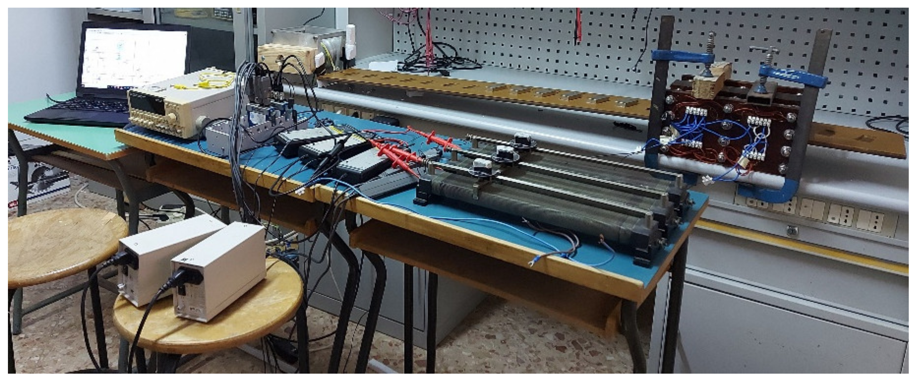
Section 4 describes the test bench set-up for the performance characterization of the two PMLG prototypes;
Section 5 describes the several open circuit measurements along with several load tests and the result obtained. Finally, in
Section 6, the conclusions regarding the comparative analysis carried out are reported.
2. Geometrical Structure of the Machines
Linear generators are usually composed of two parts: the translator, which is the movable part, and the stator, which is the fixed one. In this section, the features of the assessed machines are presented. In order to compare the effects due to the presence of iron in the stator, two machines were built, by using the same geometry. The only remarkable difference is the material used for the realization of the stator.
The general topology of the two machines consists of a symmetric dual-layer stator made from a soft ferromagnetic material for the traditional linear generator and from wood for the ironless machine.
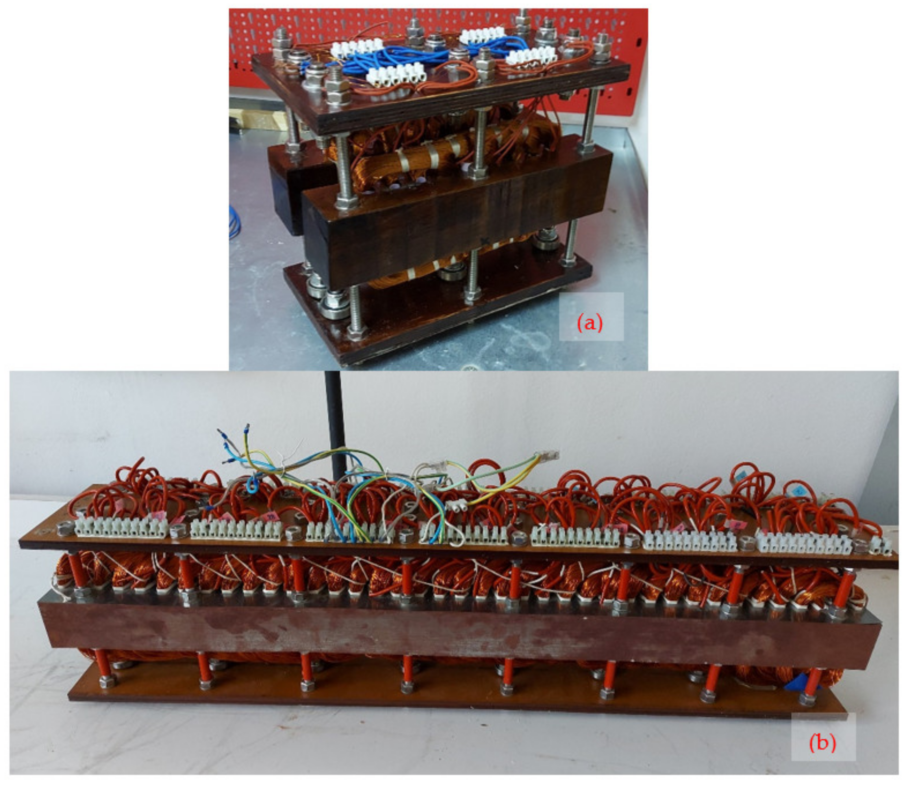
The stator is assembled to allow the linear movement of the translator between the two parts of the stators, along a ball bearing guide. In this way, both machines share the same magnetic translator that may be fitted between each of the two stators. In
Figure 1, the ironless machine (see part a) and the iron machine (see part b) are shown.
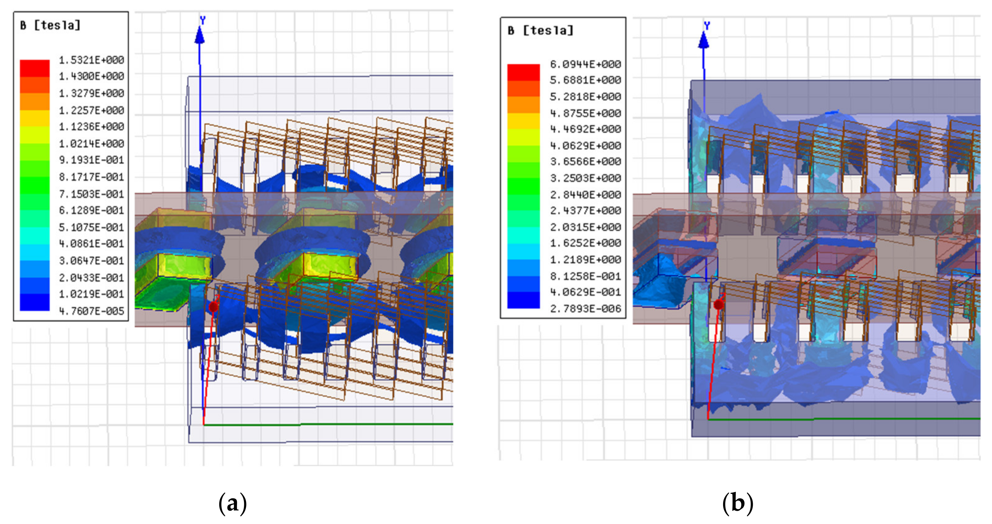
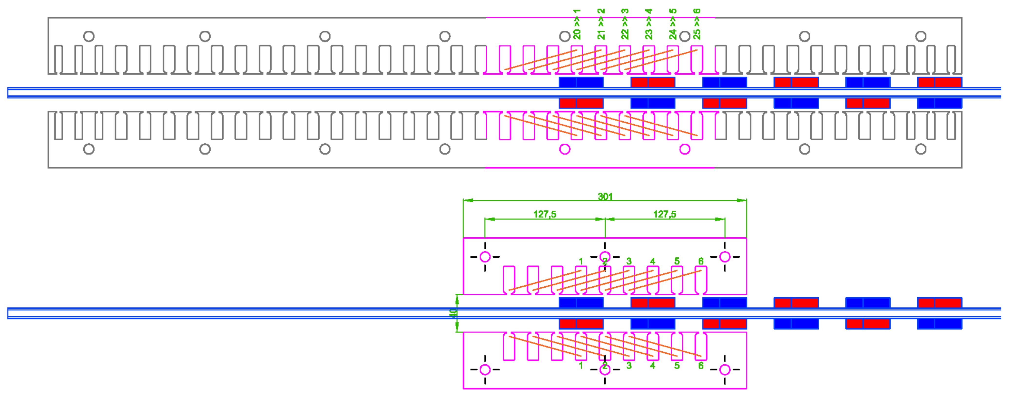
Despite the iron machine being bigger than the ironless one, they are comparable because only a part of the iron machine is connected and consequently activated. As shown in
Figure 2, the active part has the same shape in both machines. In addition to the different material of which the stator is made, the only variation is related to the position of the active part of the stator: in the iron configuration, the active part involves the coils numbered from 20 to 25, while in the ironless configuration, the entire stator is used as an active part.
The PMLG moving part is equipped with permanent magnet material according to synchronous direct-drive wave energy conversion systems requirements due to size and weight constraints [
37]. In order to ensure neutral
z-axis force components, the coils are positioned symmetrically in the stator blocks with respect to either side of the translator. The coil connection can be easily managed by placing coils in series/parallel as desired and keeping each symmetric coil pair separate. Therefore, it is possible to define a generical ‘n’ phase machine with each symmetric coil pair separate, or a conventional three-phase configuration. The former has potential benefits from an efficiency and controllability perspective as coil excitation only occurs when in close proximity to the magnetic translator, whereas the latter is more convenient if the standard power electronics systems and control aspects are considered.
In the definition of PMLG structure, the practical aspects of a complete wave energy system must be considered. In the PMLG topology definition, the following two specific areas need to be considered: (1) the wave energy source stochastic features (frequency, period and amplitude), as well as the standard range of input modes to the machine (e.g., roll, pitch, and surge); (2) PMLG controllability to enable the optimization of the mechanical resonance in light of the issue (1).
As a permanent magnet machine, no extended field flux linkage control can be achieved (e.g., field winding control) to ensure the PMLG flexible electromagnetic behavior for the wide band of the wave input variation. Consequently, for the control and real-time optimization purposes of PMLG output force and absorbed power, each symmetrical coil pair on either side of the translator will need to be coupled with a bi-directional power electronic system. In this way, the output energy can be transferred to a DC bus by the converter and, consequently, to the power grid with a final power electronic inversion stage. Otherwise, the DC bus output energy can be directly used to produce different energy sources, such as hydrogen.
Generically, to address the discussed issues, PMLG force control by the use of a power electronic stage is necessary. However, it must be noted that the two machines have not been optimized with regard to the above-mentioned factors.
Table 1,
Table 2 and
Table 3 give the mechanical and geometrical information and the value of the winding phase resistance on the two configurations of linear generators.
5. Experimental Results
As mentioned before, the main goal of this paper is the comparative analysis of the experimental performance of an iron PMLG and an ironless PMLG, which share the same geometry and same translator. For this purpose, several no-load tests and several load tests were carried out. In detail, the goal of the no-load tests was the evaluation of induced voltages trends. Conversely, the goal of the load tests was the evaluation of load voltages, output currents, output power and energy transferred to the load. In detail, the analysis of these quantities allows evaluating the cogging force negative effects on the iron PMLG performance. The PMLG performance was evaluated for three different value of input power, obtained with three different weight values of 2.5 kg, 5 kg and 7 kg, for different electric load values of 5 Ω, 10 Ω, 12 Ω, 15 Ω and 20 Ω, respectively, and with the same distance covered by the mover. In total, fifteen experimental tests were carried out for each PMLG prototype.
5.1. No-Load Test
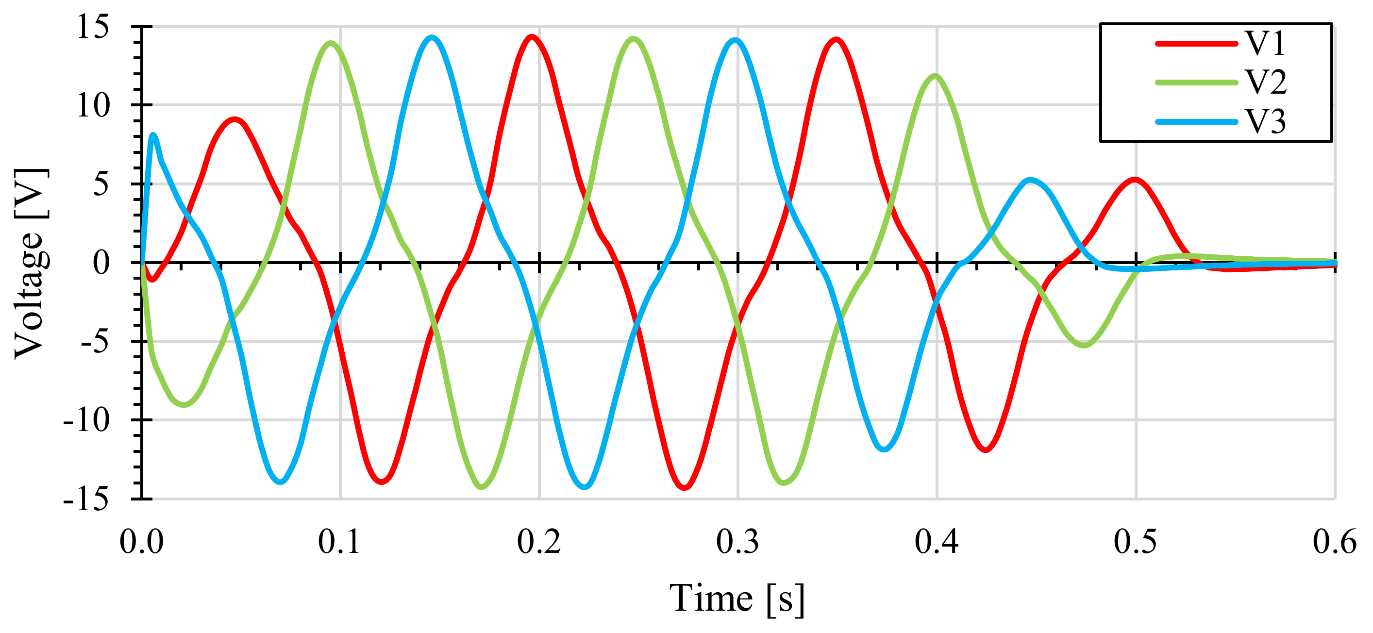
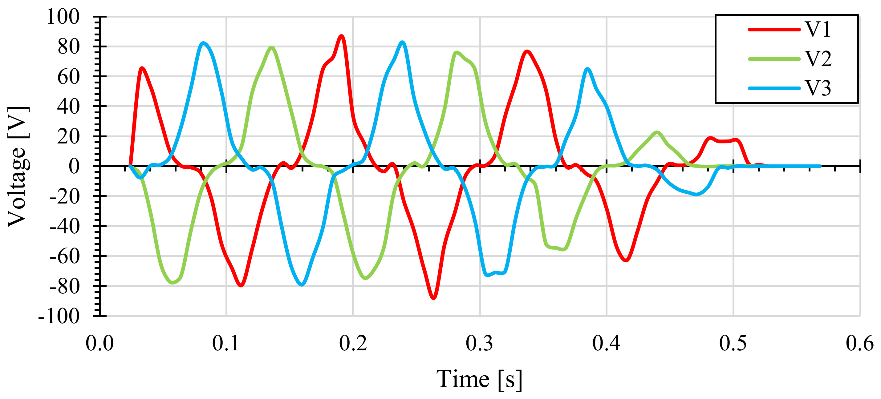
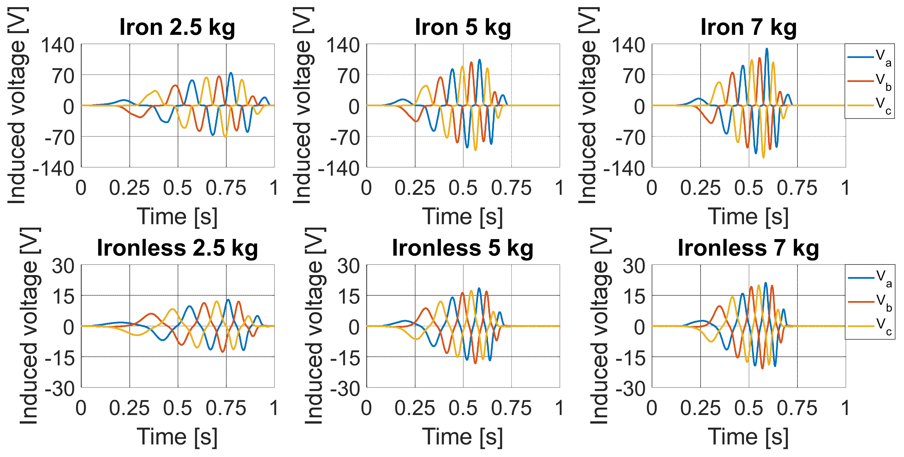
For comparison purposes, the two PMLG prototypes were equipped with two windings that present the same three-phase arrangement and equal mechanical and electrical features (wire section, number of turns, coil pitch, and pole pairs). As described in the previous section, the mechanical motion was uniformly accelerated and, therefore, this behavior resulted in a transitory evolution with an increase in the peak values of the induced voltages for both PMLG prototypes. In
Figure 9, the no-load voltage trends of iron and ironless prototypes, obtained with each input mechanical power, are reported.
The main difference between the no-load voltages of the iron and ironless PMLG prototypes is related to the peak values achieved. In detail, the induced voltages maximum peak values detected in the ironless prototype, for each input mechanical load, are 13 V, 18.5 V, and 21 V. Instead, the induced voltages with significantly greater peak values, equal to 74 V, 104 V and 130 V, were detected for the iron prototype for each input mechanical load. Moreover, the induced voltages in the iron prototype present a distorted trend that can be attributed to the tooth/slot reluctance variations, resulting in additional induced voltage harmonic components. Since there are no significant reluctance variations in the magnetic circuit of the ironless prototype, this phenomenon is absent and, therefore, no additional harmonic components are present in the induced voltages. Although this comparison highlights a significant better performance by the iron prototype in terms of the induced voltages peak value, a significant performance reduction in the iron prototype is expected in the load tests due to the cogging force and reaction armature effects. The load tests carried out are described below.
5.2. Load Test
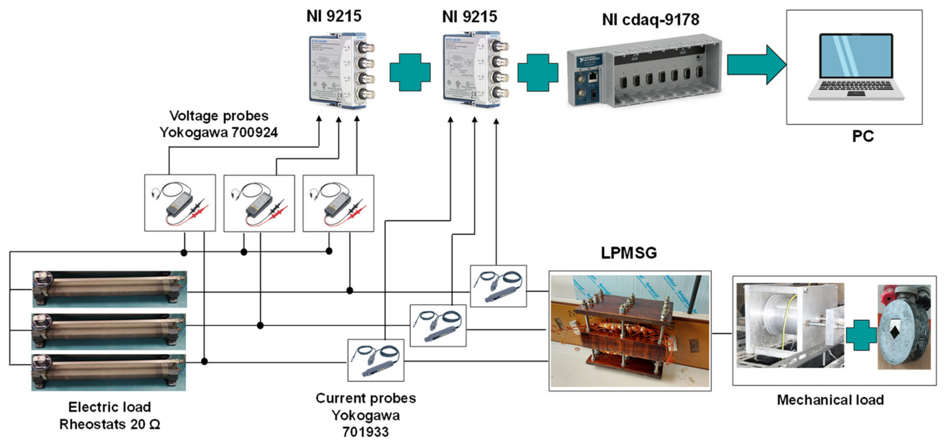
In order to evaluate the performance of the iron and ironless PMLG prototypes, several load tests were carried out. The same connection scheme was modified, adding a three-phase load, as shown in
Figure 10. Voltages were measured by using the star centre of load as the reference point (H in the figure).
In detail, for each load test, the quantities considered for comparison purposes are the load voltages, the load currents, the energy dissipated by the load, efficiency and the respective output average load power. Although it was possible to evaluate the ironless prototype performance for the three input mechanical loads of 2.5 kg, 5 kg and 7 kg and for each resistive load value, it was only possible to evaluate the iron prototype performance for the input mechanical loads of 5 kg and 7 kg due to the presence of the cogging force. This result shows that only in the presence of high mechanical loads the translator can be set in motion and it is possible to transfer energy to an electrical load. This feature is very penalizing in the application of sea wave power generation as it reduces the range of usable wave height for electrical energy generation. Therefore, the performance comparison between the two PMLG prototypes was carried out with a mechanical load equal to 5 kg and 7 kg.
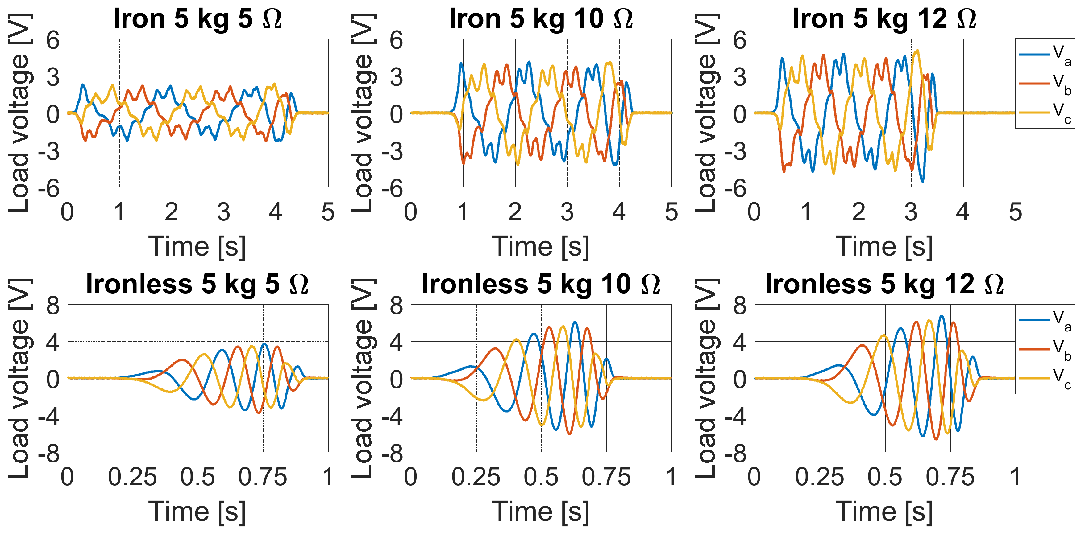
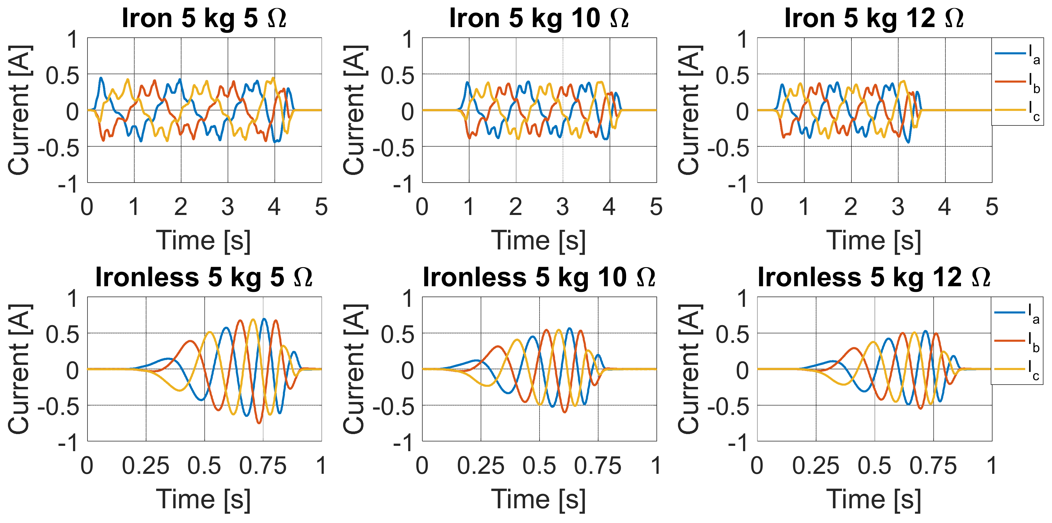
The load voltages and load currents trends detected for the two PMLG prototypes, with an input mechanical load of 5 kg and for electric load values of 5 Ω, 10 Ω, and 12 Ω, are reported in
Figure 11 and
Figure 12, respectively.
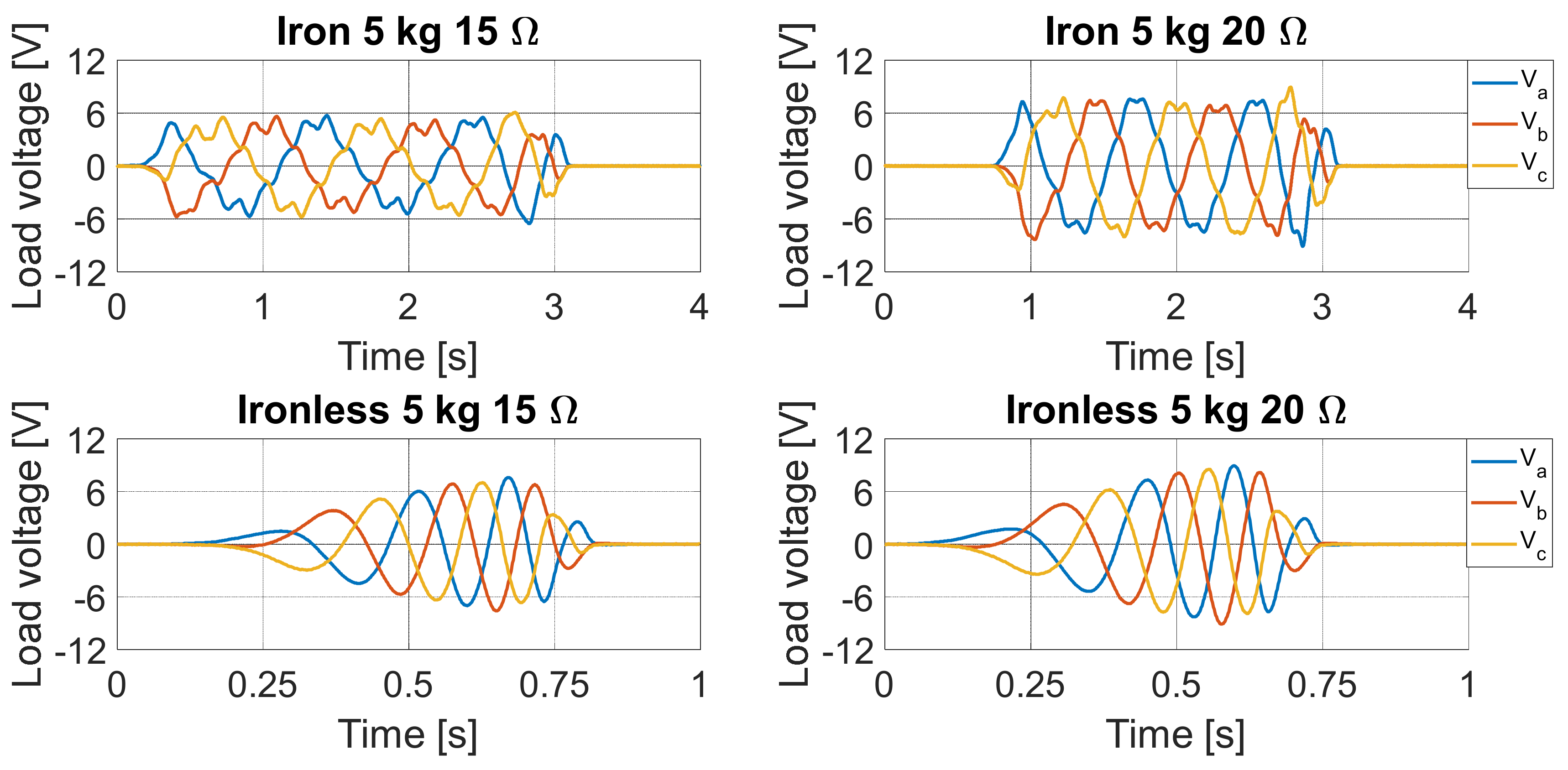
Figure 13 and
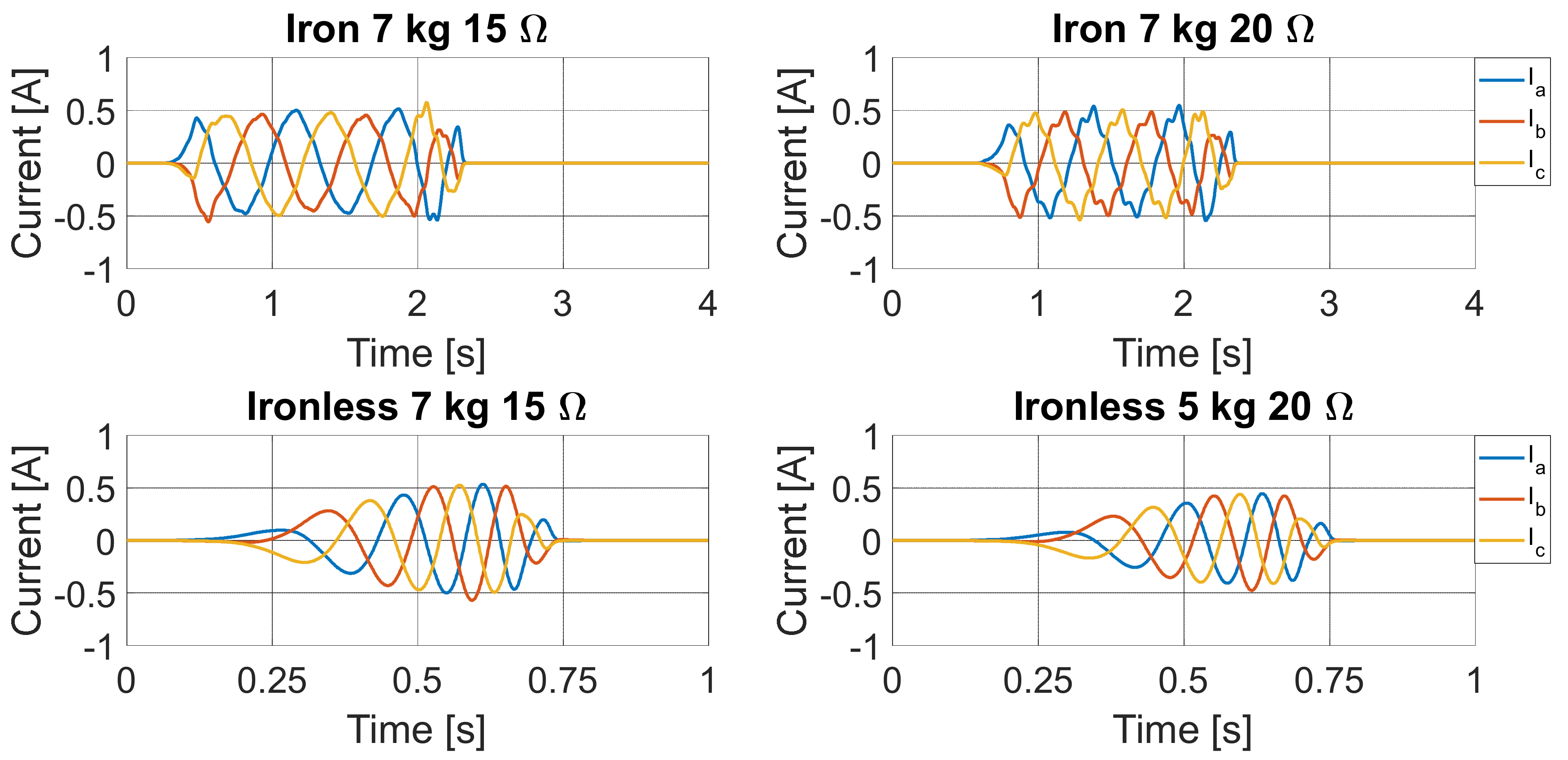
Figure 14 report the load voltages and load currents trends detected with the input mechanical load of 5 kg and for electric load values of 15 Ω and 20 Ω, respectively. It is interesting to observe that the ironless PMLG prototype presents better performances in terms of load voltage and current peak values with respect to the iron PMLG prototype, for each resistive load value. A significant reduction in the voltage at the iron PMLG prototype terminals was detected with respect to the no-load operation, which can be attributed both to the cogging phenomena and to the armature reaction effects. In the case of the ironless PMLG prototype, the armature reaction slightly affects the output voltages. Moreover, the load voltages and load currents obtained with the iron PMLG prototype present distorted trends due to cogging phenomena.
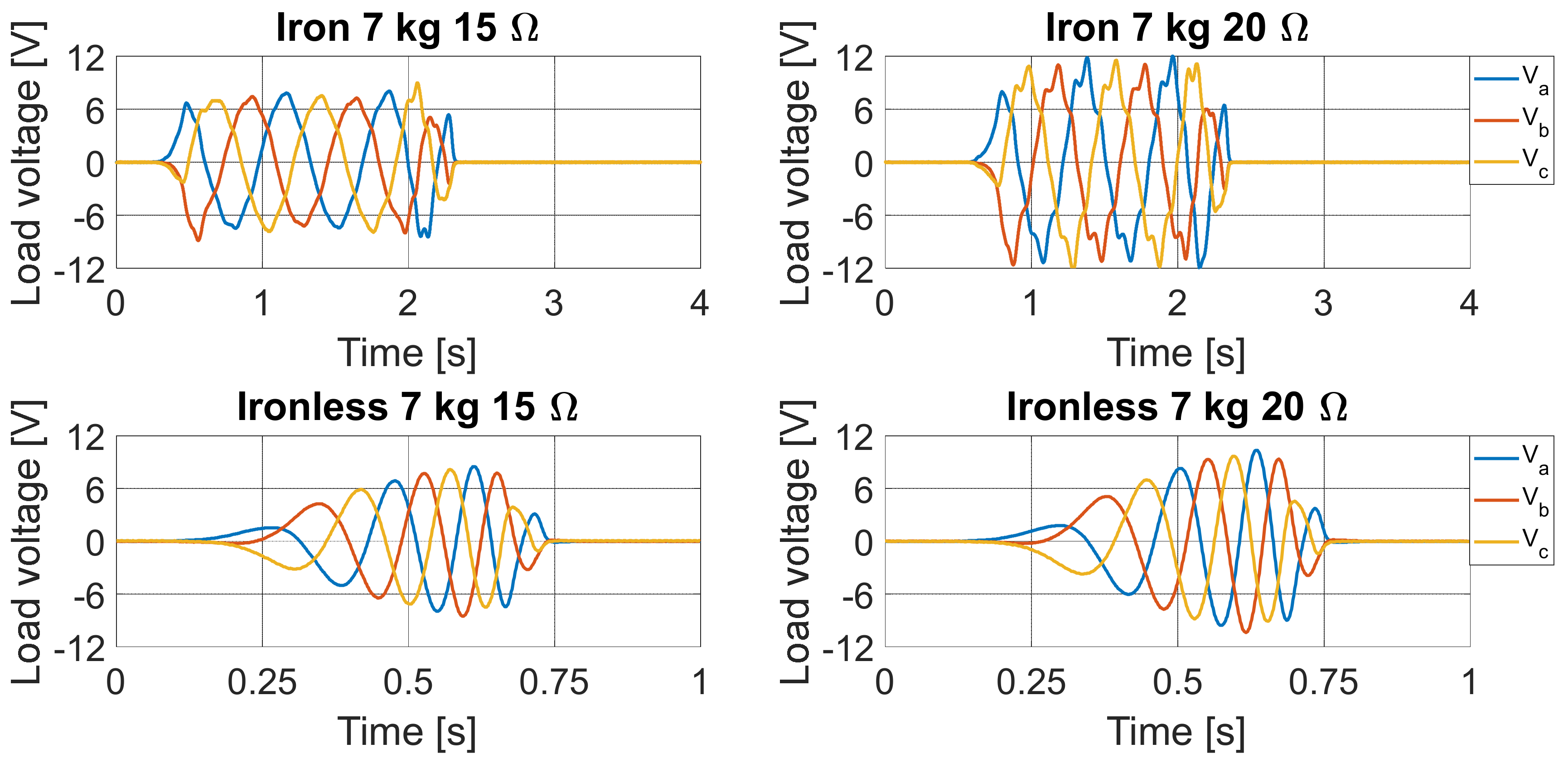
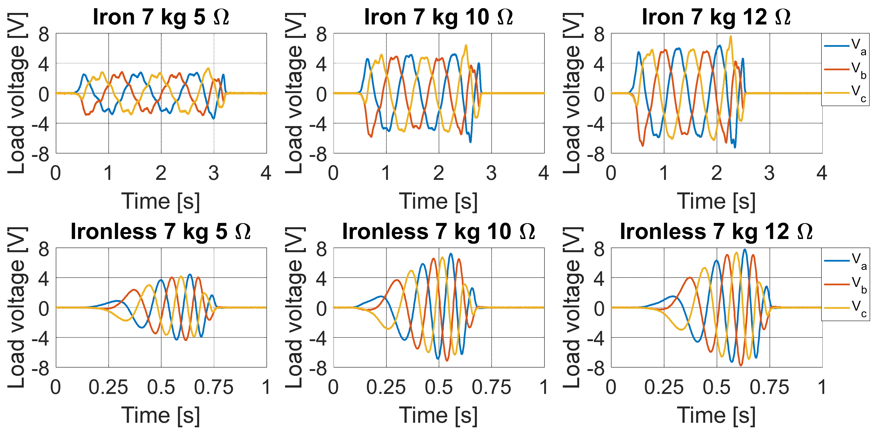
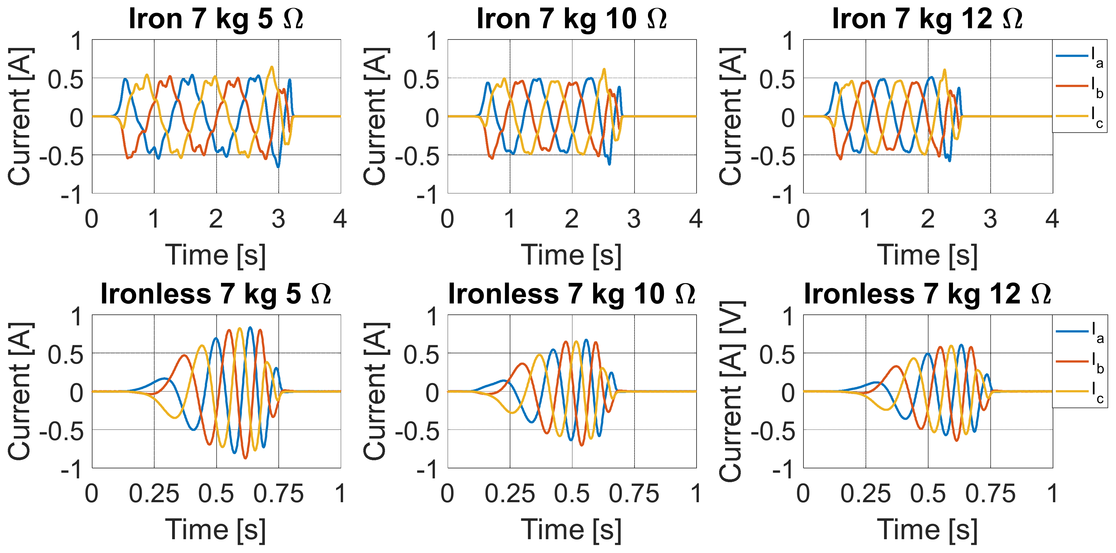
The load voltages and load currents trends detected for the two PMLG prototypes, with the input mechanical load of 7 kg and for electric load values of 5 Ω, 10 Ω, and 12 Ω, are reported in
Figure 15 and
Figure 16, respectively.
Figure 17 and
Figure 18 report the load voltages and load currents trends detected with a mechanical load of 7 kg and for the electric load values of 15 Ω and 20 Ω, respectively. Additionally, in this case, it is possible to observe that the ironless PMLG prototype presents better performances in terms of load voltage and current peak values with respect to the iron PMLG prototype for each resistive load value, except for the resistive load value of 20 Ω. Compared to the previous case, a higher mechanical load involves an increase in the translator speed, which is reflected in an increase in the amplitudes of currents and voltages peak values. Moreover, it is possible to observe less distortion in the iron prototype voltage and current trends that can be attributed to the increase in the fundamental voltage harmonic component. The voltage and current values acquired in each test were used to calculate the total load instantaneous power. In detail, the total instantaneous power
ptot(
t) was computed as the sum of the instantaneous powers of each load phase:
Therefore, the energy was evaluated by integrating the total load instantaneous power with respect to time using the following relationship:
where
t0 and
tf are the motion initial time instant and the motion final instant, respectively.
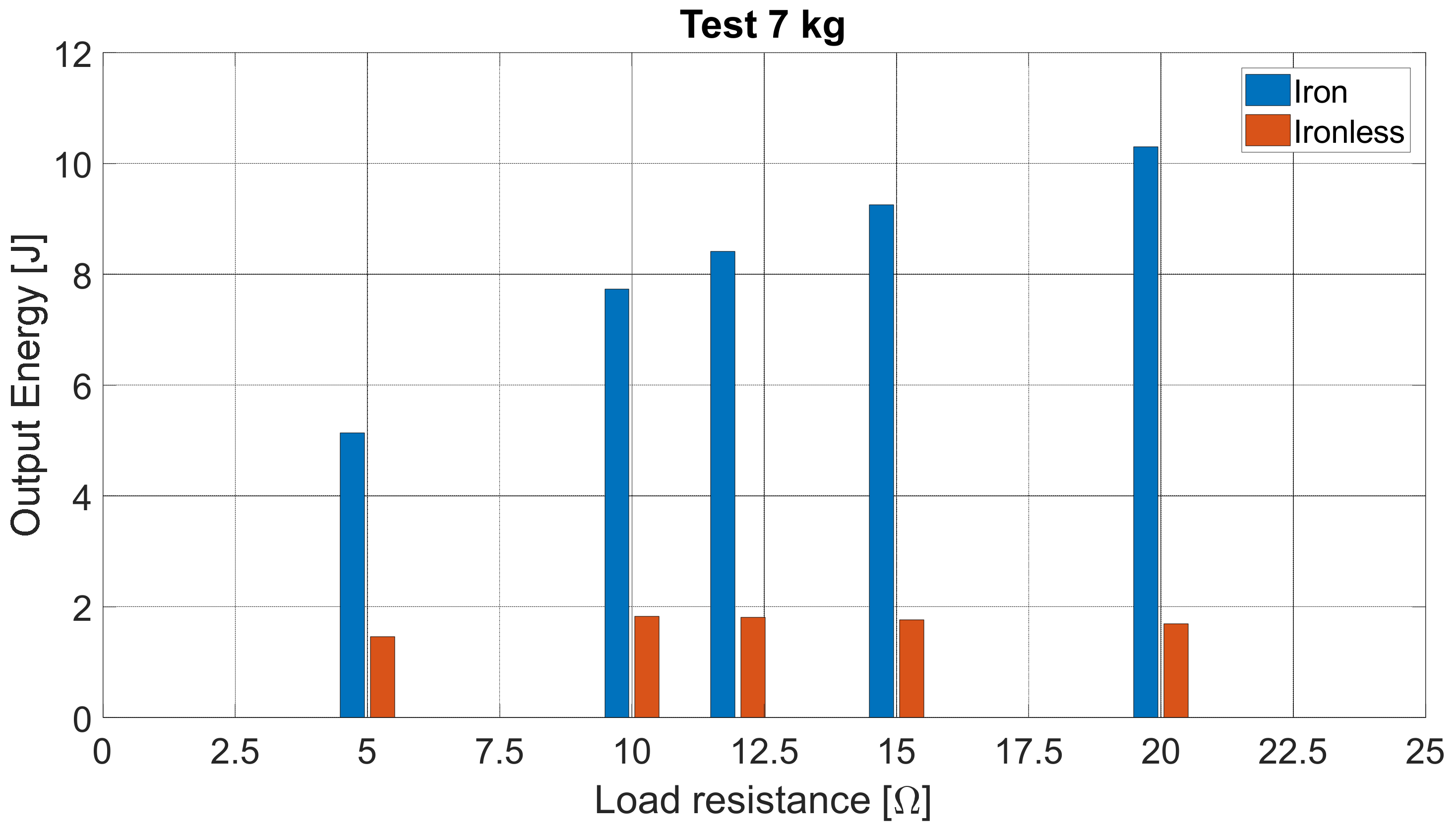
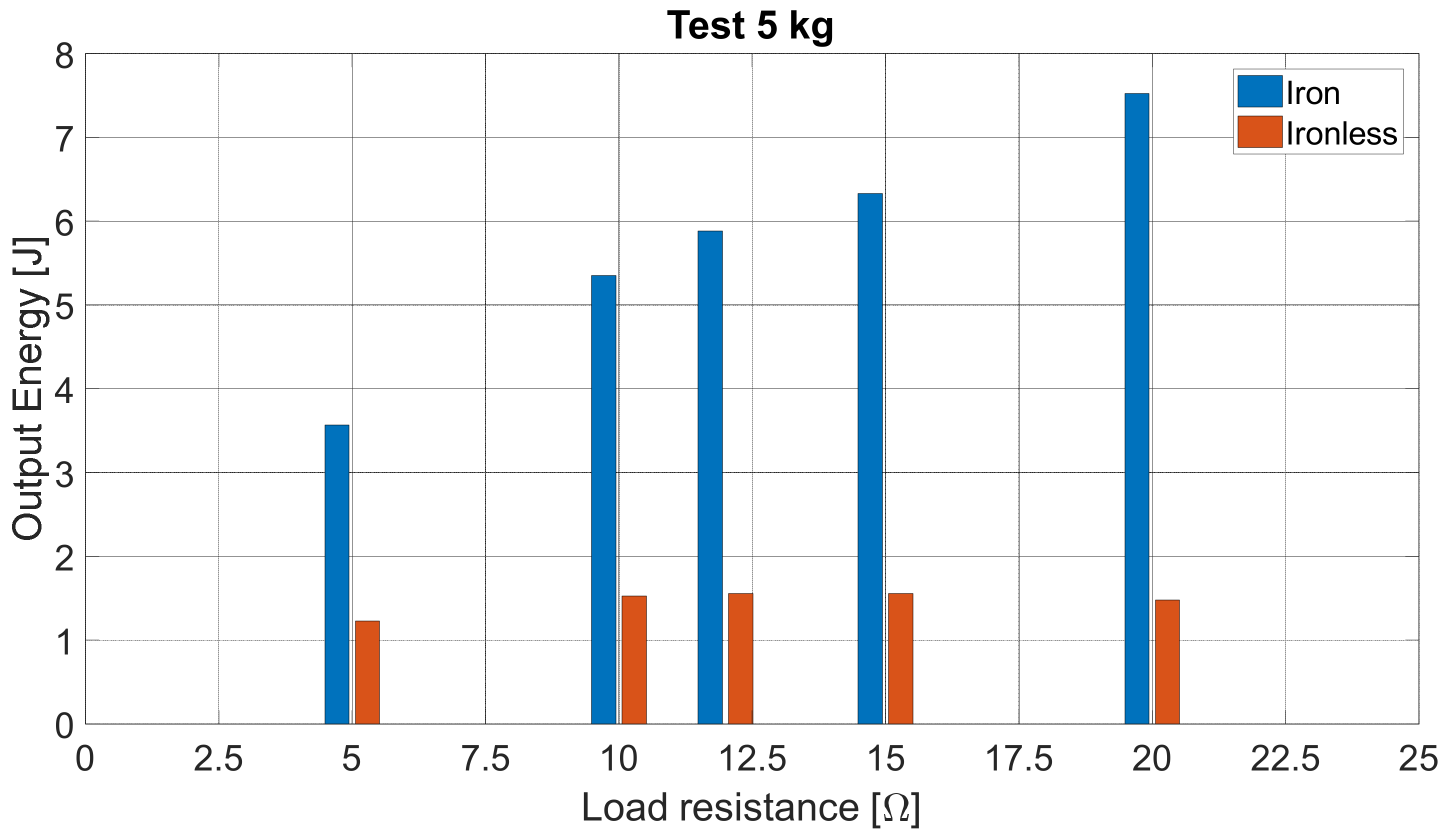
Figure 19 and
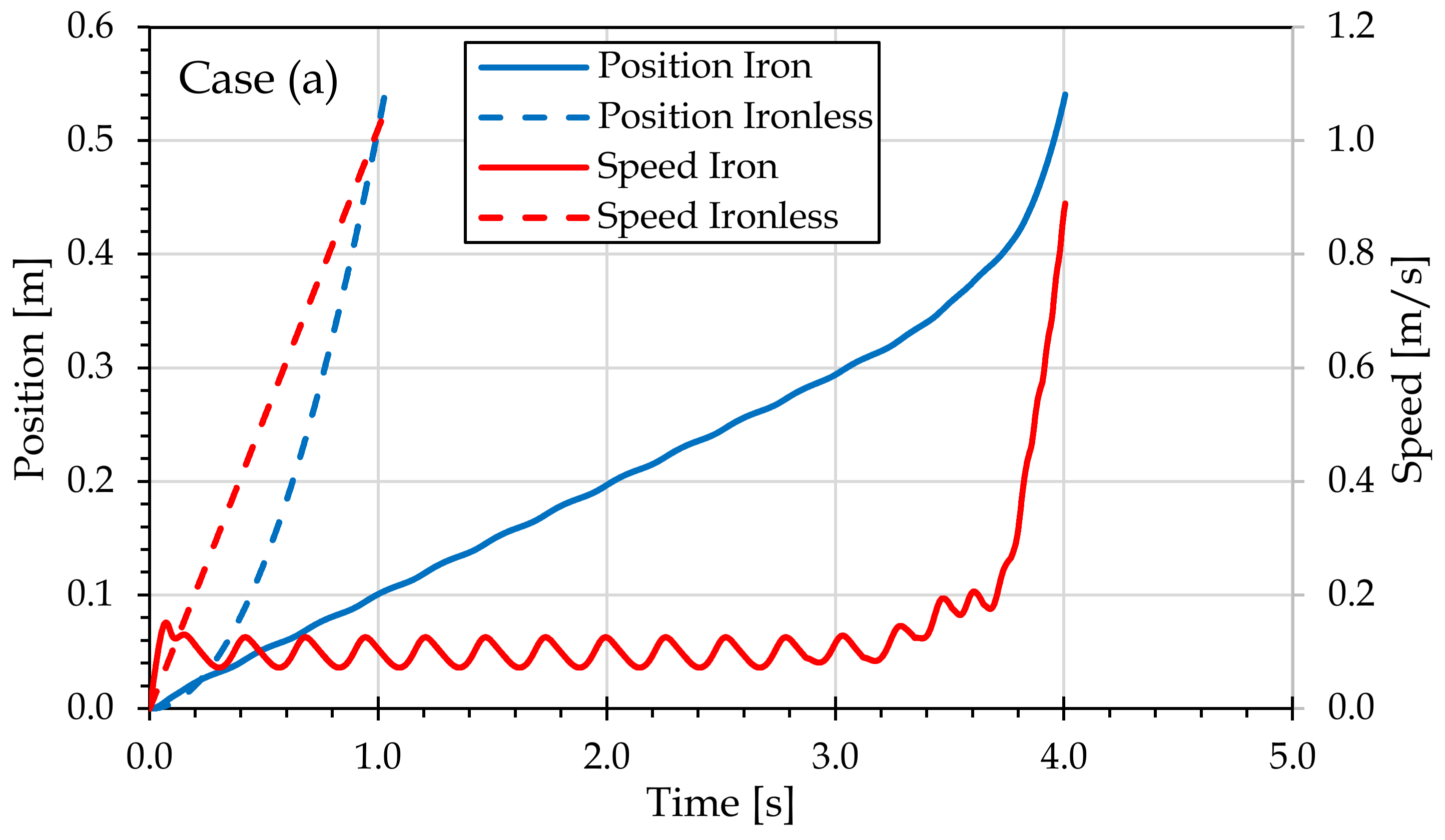
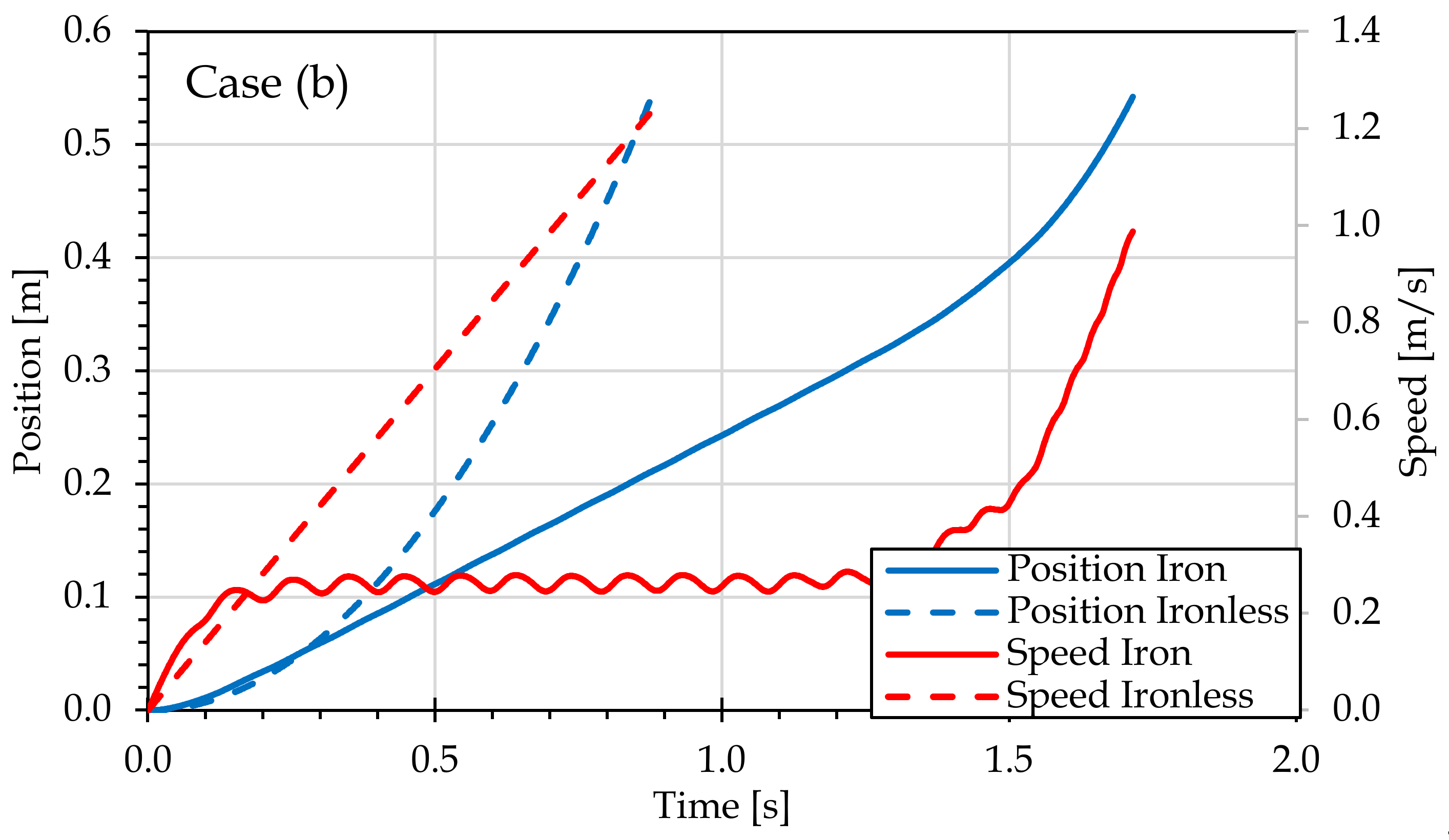
Figure 20 report the electrical energy transferred to the load by the two PMLG prototypes for each resistive load value and for each mechanical load, respectively. It is possible to observe that the iron PMLG prototype presents better performances in terms of the electrical energy transferred to the load with respect to the ironless PMLG prototype. This result is attributed to the presence of the cogging phenomenon, armature reaction and end effects in the iron prototype that results in an irregular motion of the translator characterized by a significant reduction in speed with respect to the motion of the ironless prototype. The motion dynamics of the iron prototype translator is much slower respect those of the ironless prototype and it can be appreciated in the analyzed voltage and current trends. For a more accurate comprehension, by way of example, the position and speed trends of each PMLG prototype, detected in the short circuit test and load test with a resistive load equal to 20 Ω at an input mechanical load equal to 7 kg, are reported in
Figure 21.
Regarding the efficiency comparison analysis, it is necessary to highlight that the tests were carried out with a mechanical load that travels a definite distance and dissipates the total kinetic energy hitting a surface, and this quantity presents different values in the two prototypes since the motion dynamic is quite different. The ironless PMLG prototype kinetic energy is considerably higher than of the iron PMLG prototype, as can be appreciated by
Figure 21. Therefore, in the efficiency computation, the kinetic energy quantities were excluded since in real applications the dissipation of the kinetic energy does not occur instantaneously through a collision, but much of it can be converted into useful energy for the electric load. The kinetic energy of the translator
Et and the weight
Ew can be easily computed as:
where
mv,
mt and
v(
tf) are the mass of translator, the mass of weight and the speed value at instant of collision
tf, respectively. Therefore, the efficiency was evaluated by the following relationship:
where
Ein,
Eout are the input energy and the output energy or the energy transferred to the electric load, respectively.
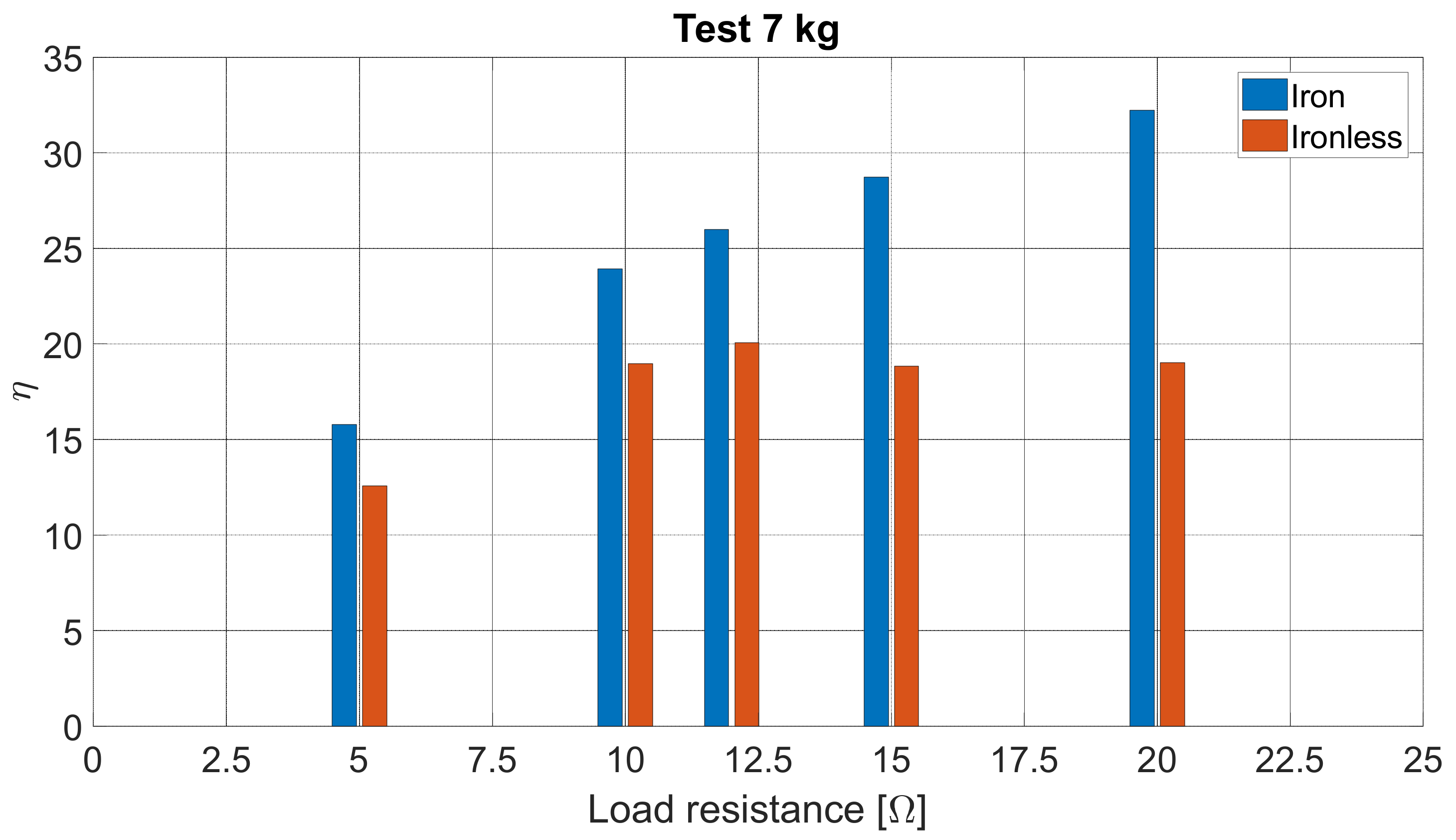
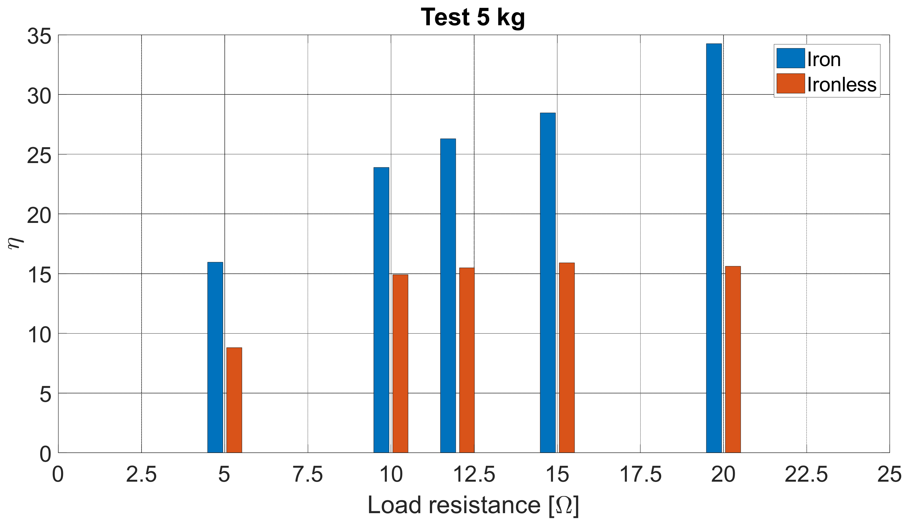
Figure 22 and
Figure 23 report the efficiency values of the PMLG prototype detected for each resistive load value and for an input mechanical load equal to 5 kg and 7 kg, respectively. High efficiency values were not identified in both PMLG prototypes because a large amount of mechanical losses are present in the tested system. In detail, it is possible to observe that the efficiency values of the iron PMLG prototype do not significantly vary as the input mechanical load increase. This result highlight that the dynamic of the iron PMLG is significantly affected by the cogging and end effects, which limit the efficiency of the iron PMLG prototype. Contrariwise, an increase of 4–5% in the ironless PMLG prototype efficiency values was detected as the input mechanical load increases for each resistive load value. Moreover, in the test for the 7 kg input mechanical load, the efficiency values of the iron PMLG were significantly higher than of the ironless one, only at high values of the resistive load.
As mentioned before, since the motion dynamics of the two PMLG prototypes are very different, the average power was considered as a comparison index for performance comparison purposes. The average power was calculated as the ratio between the determined energy values
Eout and the respective time intervals of motion Δ
t for each load and mechanical working conditions:
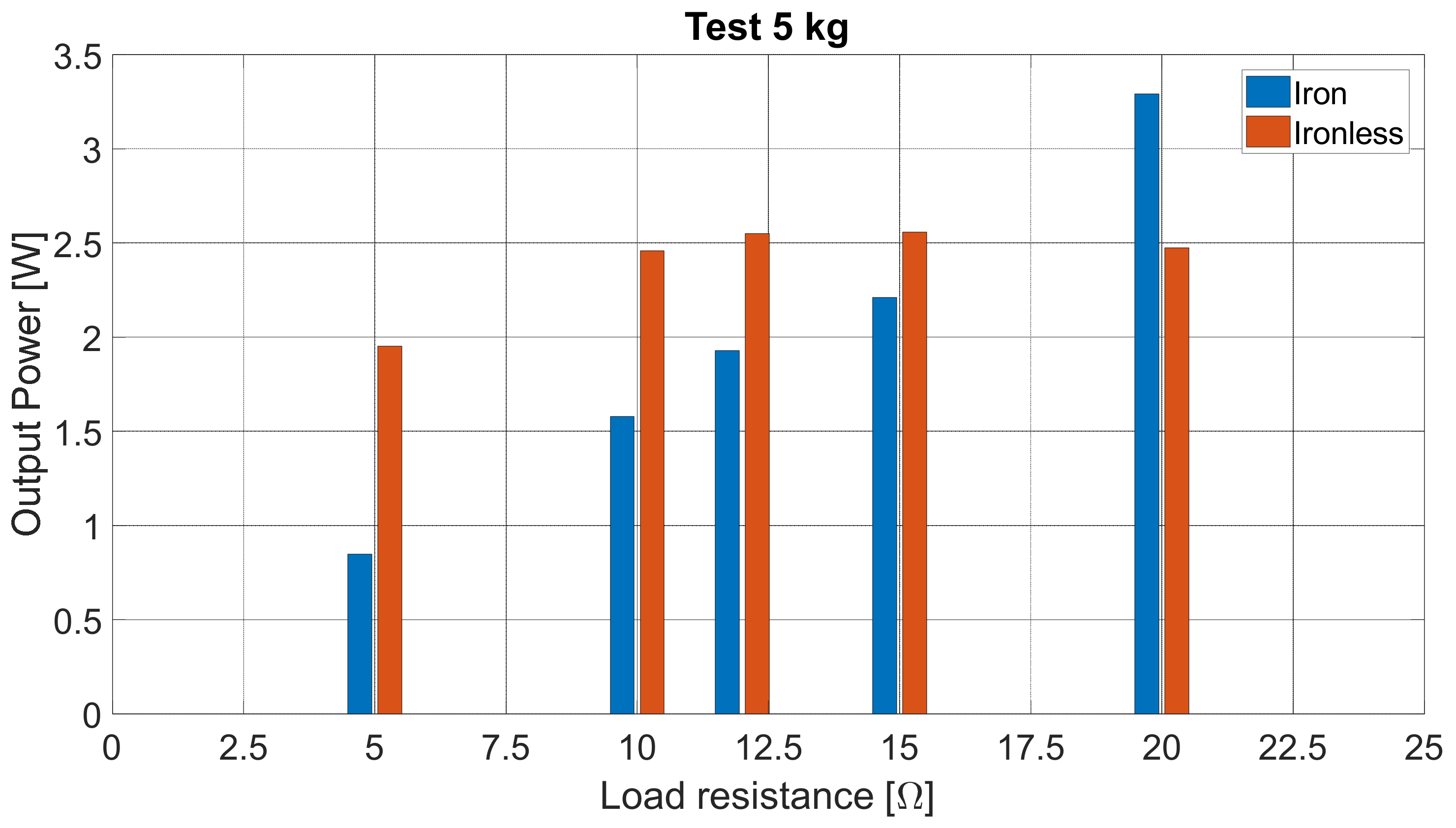
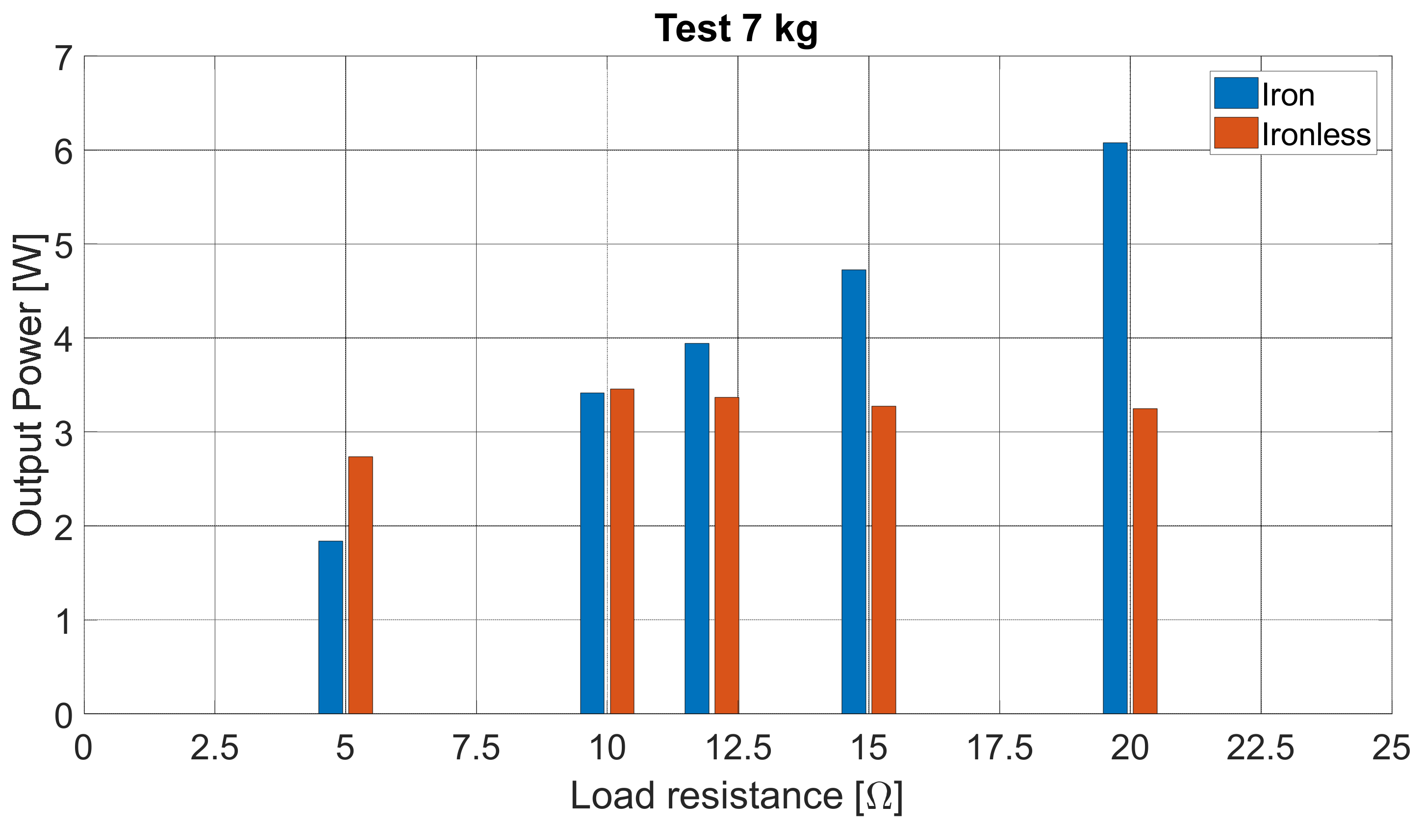
Figure 24 and
Figure 25 report the output power of the two PMLG prototypes for each resistive load value and for input mechanical load equal to 5 kg and 7 kg, respectively. In detail, it is possible to observe that the two PMLG prototypes present a comparable performance. In the test with an input mechanical load of 5 kg, the iron PMLG prototype presents a higher performance with respect to the ironless prototype only for a resistive load value equal to 20 Ω. In the test with an input mechanical load of 7 kg, the iron PMLG prototype presents a higher performance with respect to the ironless prototype in almost all electrical load values.
The experimental comparative analysis carried out highlights as the iron PMLG prototype performances in terms of efficiency are significantly better than those of the ironless prototype only for high resistive load, whereas the iron PMLG prototype performances in terms of average power are comparable to those of the ironless prototype. The main identified disadvantage is related to the energy values transferred to the electrical load. However, taking into account the application requirements relating to wave energy conversion, considerable less weight and the absence of parasitic phenomena in ironless PMLG prototype, such as cogging and end effects, represent very important features because it allows moving the ironless prototype translator with a mechanical load that is significantly lower with respect to the iron prototype. In detail, it is the experiments that revealed that the ironless machine is able to achieve a higher speed in a more regular way thanks to the absence of the cogging force. Thus, for sea wave energy harvesting, the iron configuration produces vibrations, requiring a higher thrust to activate the machine, while the ironless is characterized by a more regular trend. This could be a relevant aspect to increase the energy extraction from waves since this kind of machine could also be activated by smaller waves. From this analysis emerges that the performance gap between the two PMLG prototypes, in terms of transferable energy to the load, can be further reduced.
6. Conclusions
In this paper, an experimental comparison analysis between the performance of an iron PMLG prototype and an ironless PMLG prototype, which share the same geometry, was presented. In detail, the two PMLG prototypes present the same three-phase arrangement and equal mechanical and electrical features. Several open circuits and load tests were performed with the same distance covered by the mover. As expected, the analysis carried out by the no-load tests showed that the iron PMLG prototype presents better performances in terms of induced voltage peak values with respect to the ironless PMLG prototype. However, the experimental results obtained by the load-test highlighted a significant reduction in the iron PMLG performance until to comparable values those of the ironless PMLG prototypes. In detail, the main results of the performance comparison, between the two PMLG prototypes, are summarized below:
The peak values of the load voltages and currents voltage obtained with the two PMLG prototypes are comparable for fixed values of input mechanical load and output electric load;
The iron PMLG prototype presents higher performances in terms of transferred energy to the load with respect to the ironless PMLG prototype;
The absence of parasitic phenomena in the ironless PMLG prototype, such as cogging and end effects, allows moving the ironless prototype translator with a mechanical load that is significantly lower with respect to the iron prototype. This feature can reduce the gap in terms of transferable energy to the load by the two PMLG prototypes;
There is no significant increase in the iron PMLG prototype efficiency values as the mechanical load increases, due to the presence of parasitic effects;
An increase of 4–5% in the ironless PMLG prototype efficiency values was detected for each resistive load value as the mechanical load increases;
The performances of the two PMLG prototypes, in terms of average power, are comparable.
The comparative analysis was carried out on two PMLG traditional that share the same geometry, the same winding and the same permanent magnets geometrical disposition. Obviously, the performance gap between the two PMLG prototypes can be further reduced by the adoption of optimization proposals, such as the optimal disposition of permanent magnets in order to improve the flux linkage with the stator windings. Therefore, ironless PMLGs are a fascinating solution for sea wave applications since they are lighter than iron PMLGs, do not suffer from negative effects related to the cogging phenomena and are able to work with low values of the mechanical input load, which results in a significant increase in the wave height that can be used for the electrical energy production.


 ,
, 


