
Development and Wave Tank Demonstration of a Fully Controlled Permanent Magnet Drive for a Heaving Wave Energy Converter


Abstract
:1. Introduction
2. Wave Energy
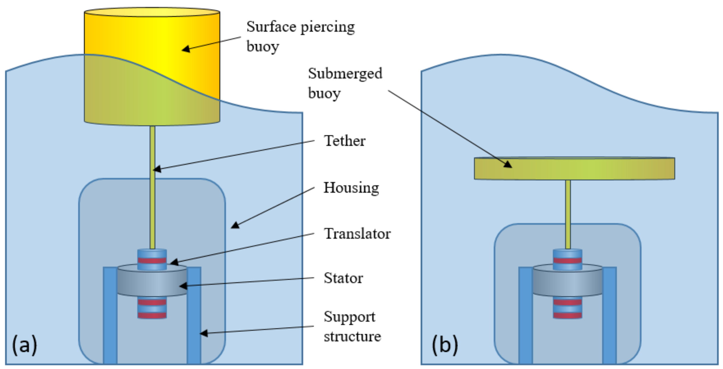
2.1. Model of the Wave Energy Converter
2.2. Electric Power Take-Off Specification
3. Generator Topologies
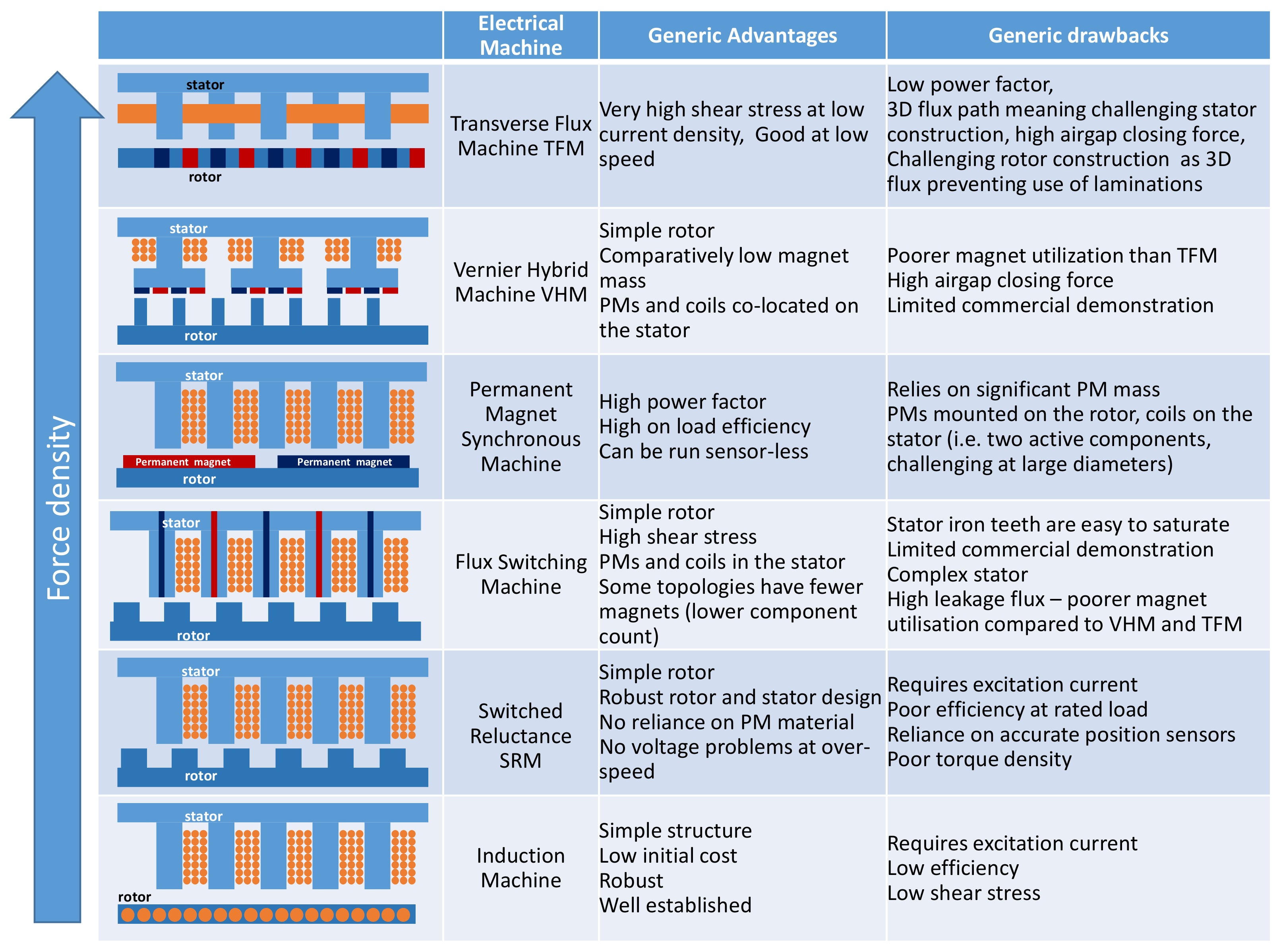
3.1. Alternative Topologies
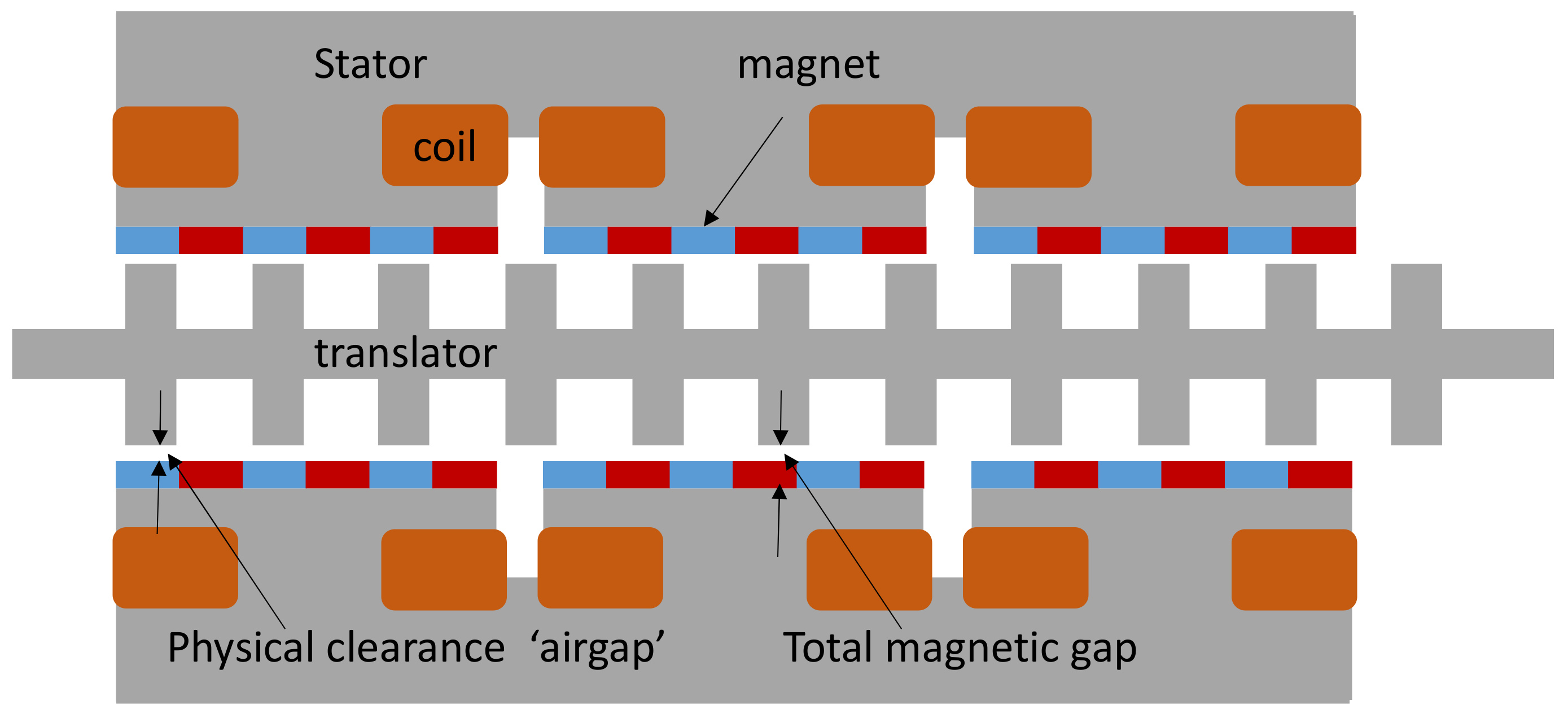
3.2. The Vernier Hybrid Machine
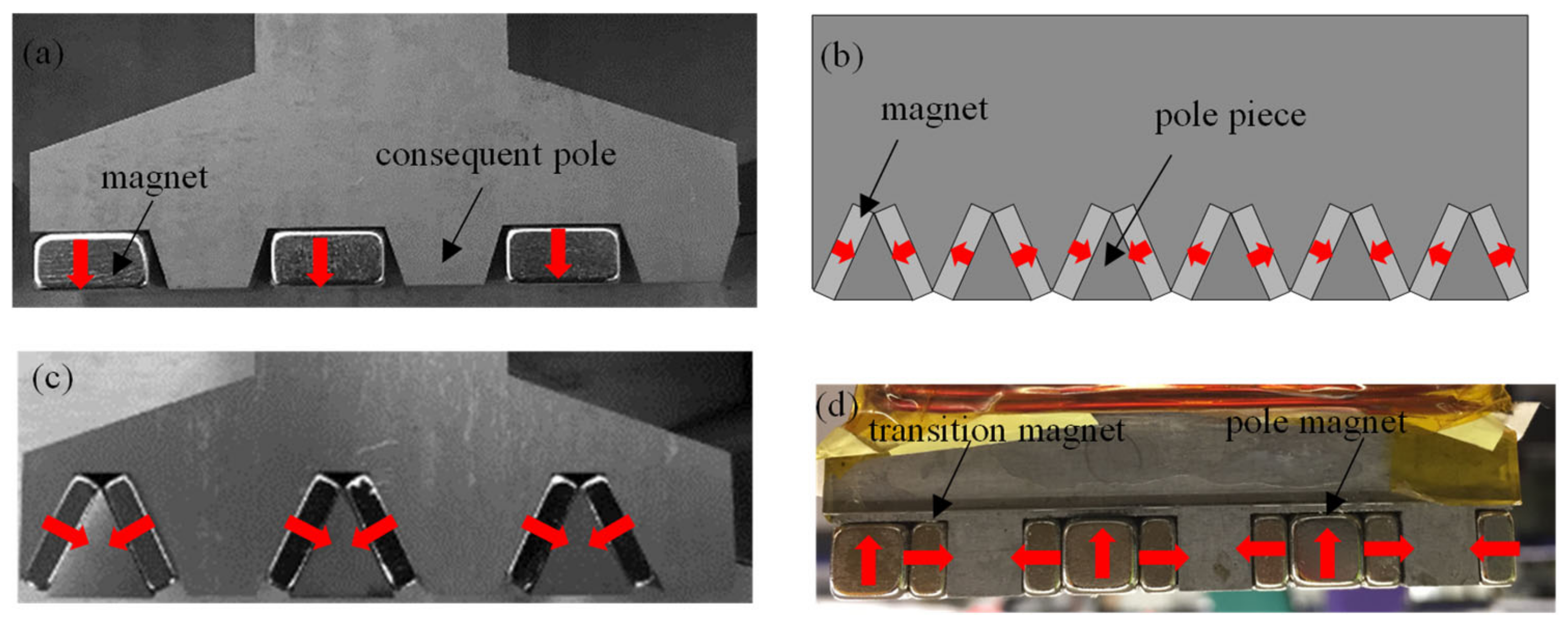
3.3. Stator Pole Topologies
3.3.1. Consequent Poles
3.3.2. Flux Concentration
3.3.3. Flux Concentration with Consequent Poles
3.3.4. Halbach Array with Consequent Poles
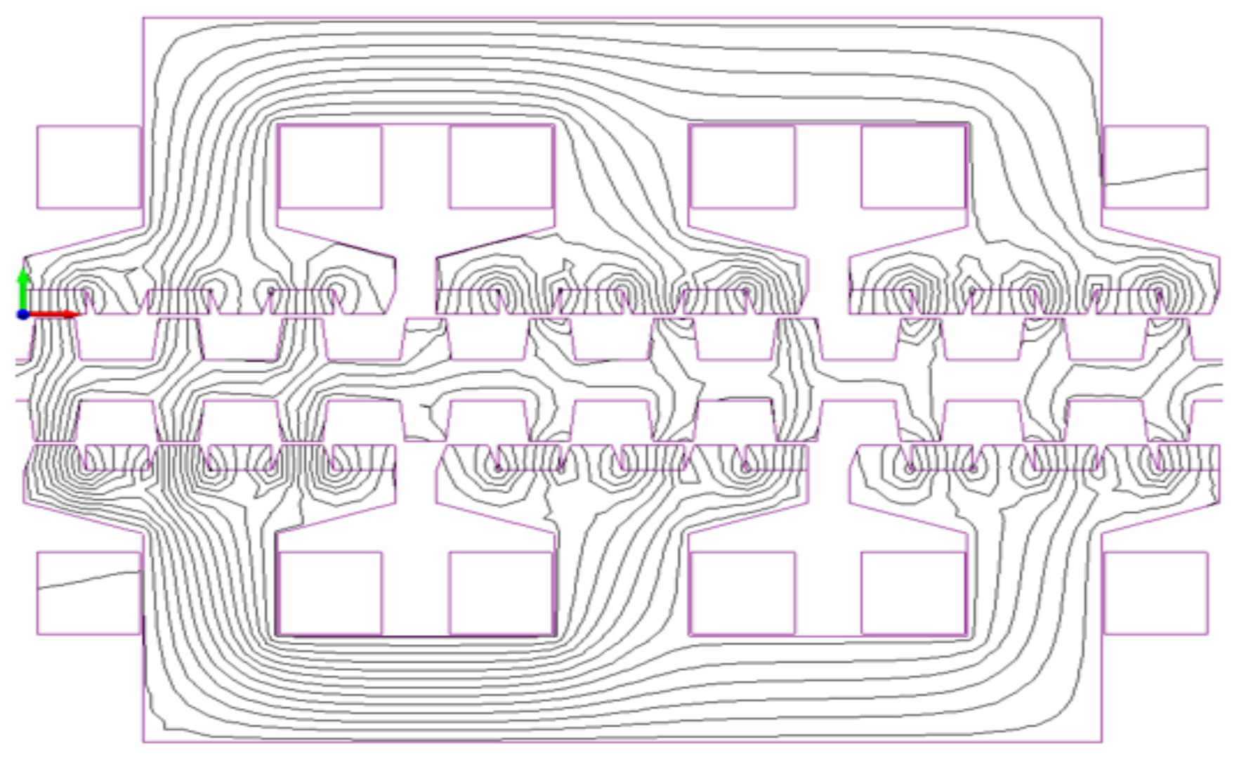
3.3.5. Topology Comparison
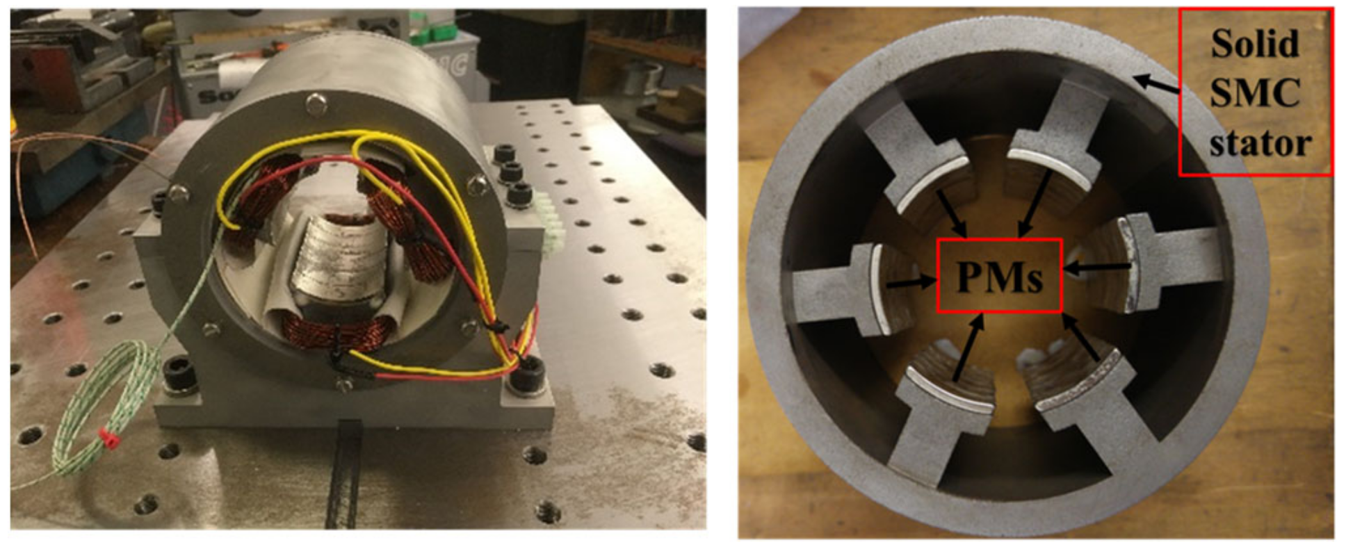
3.4. Cylindrical Topologies
3.5. Topology Selection and Build
4. Power Converter
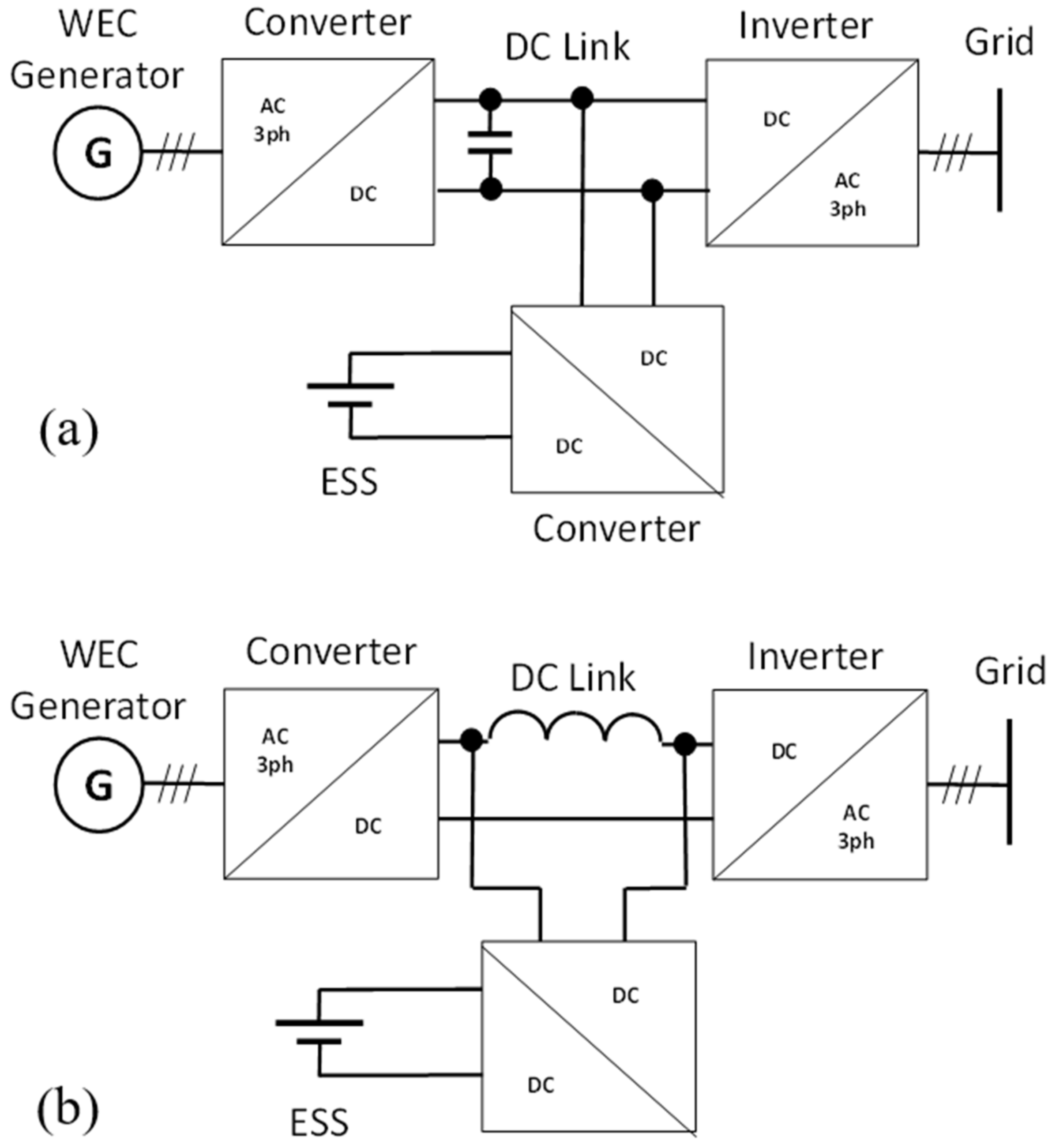
4.1. Options
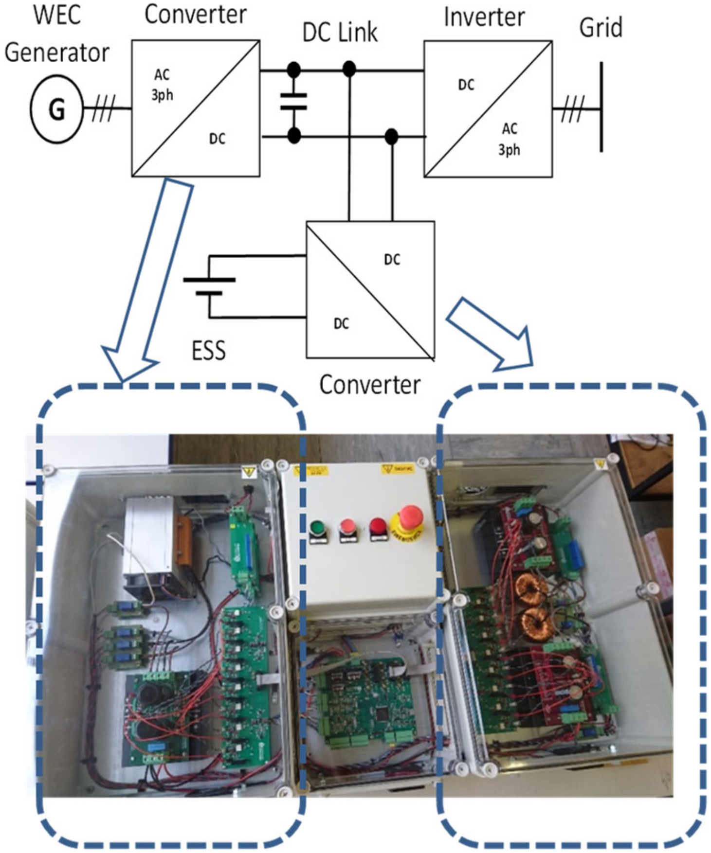
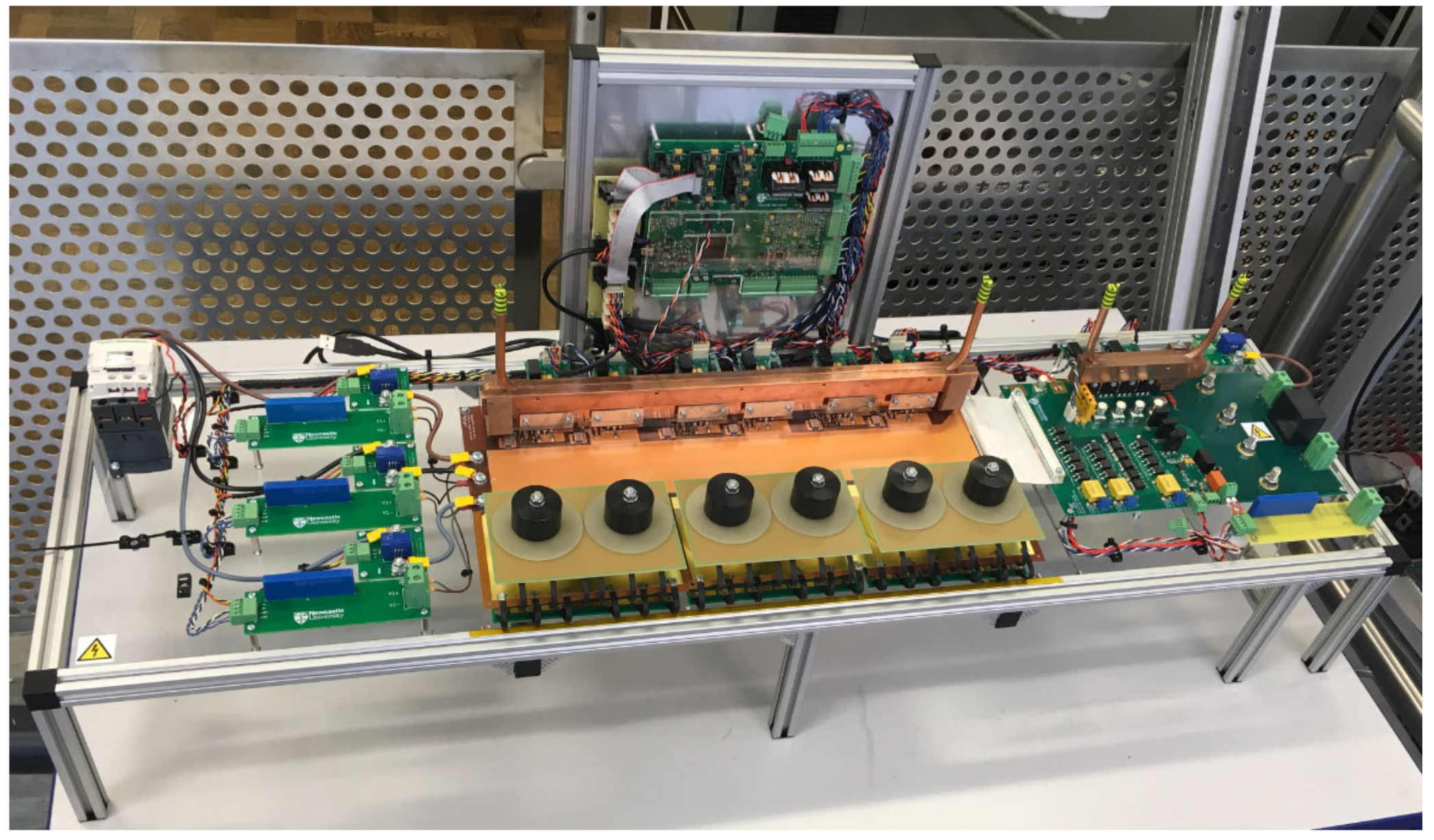
4.2. Selection and Build
5. Wave Tank Testing
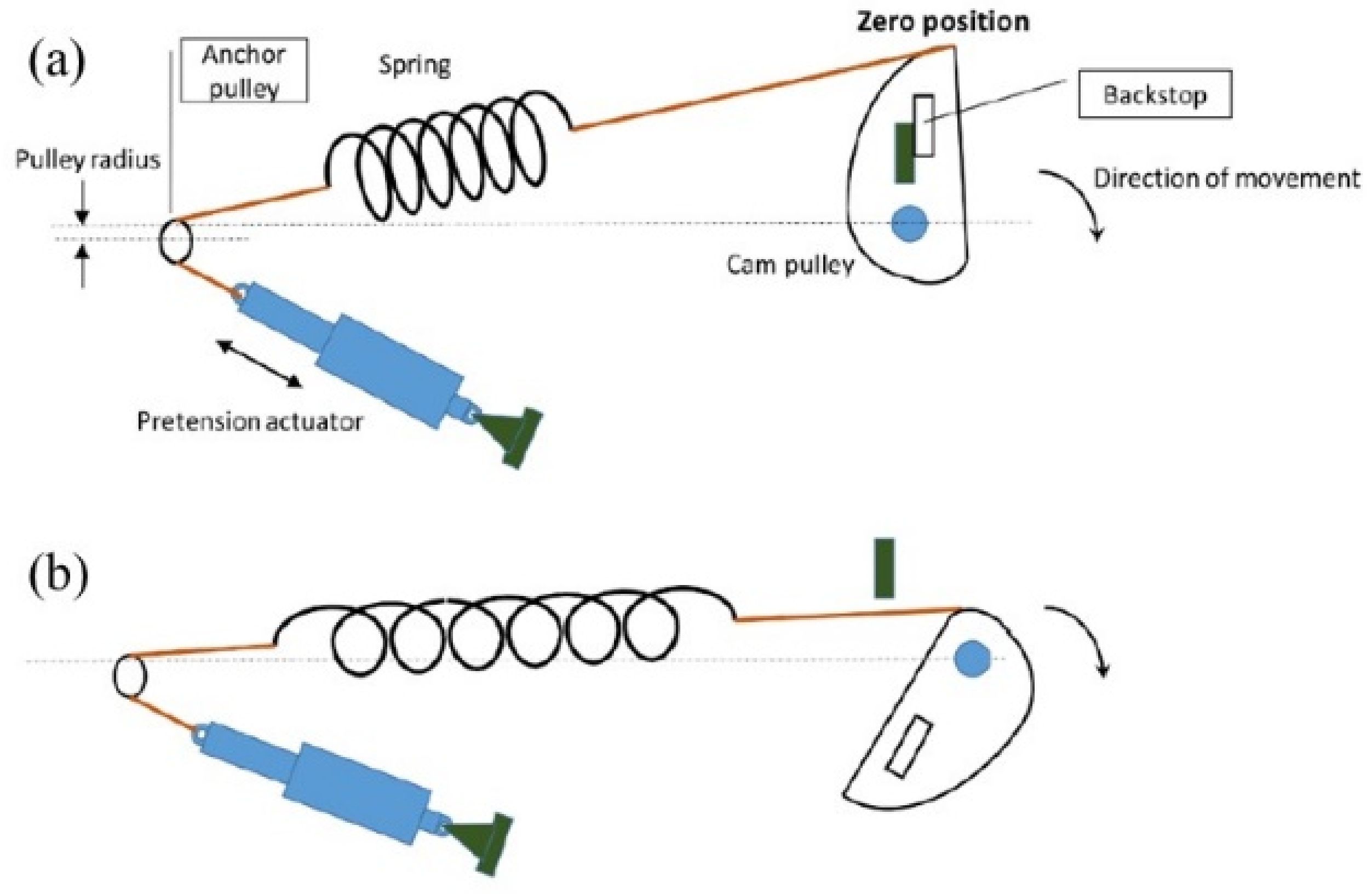
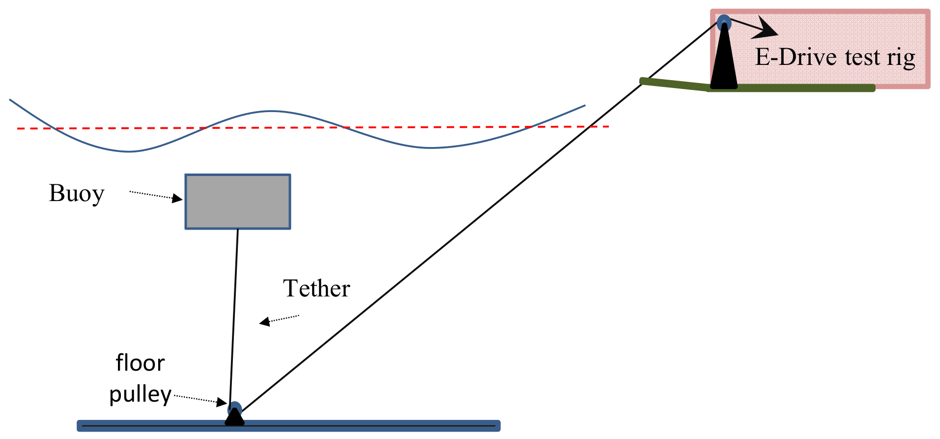
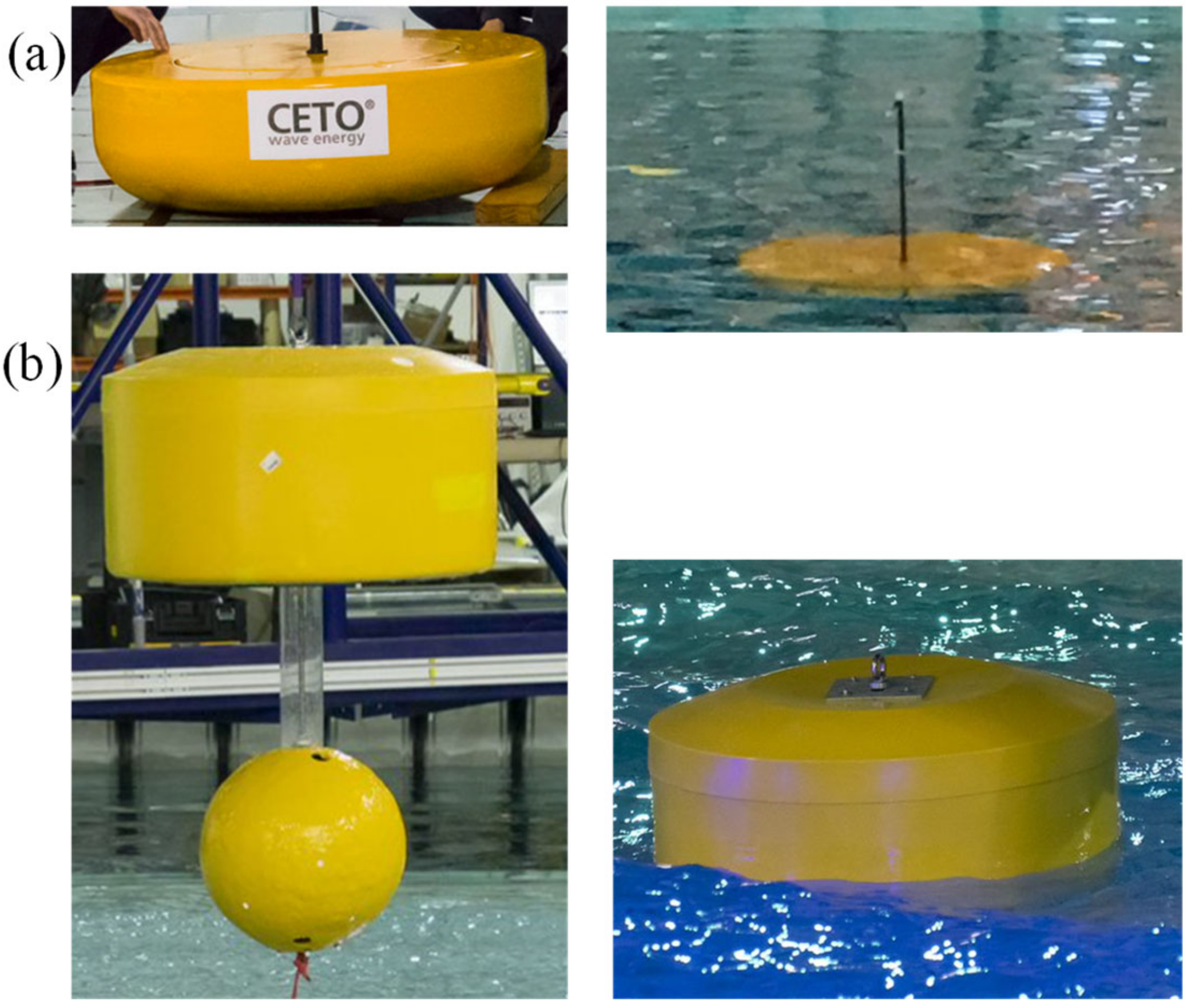
5.1. Test Setup
5.2. Wave Tank Testing
5.3. Steady State Operation
5.4. Case Study 1: Damping Variation in a Non-Resonant System
5.5. Case Study 2: Resonant Systems and Spring Force Variation
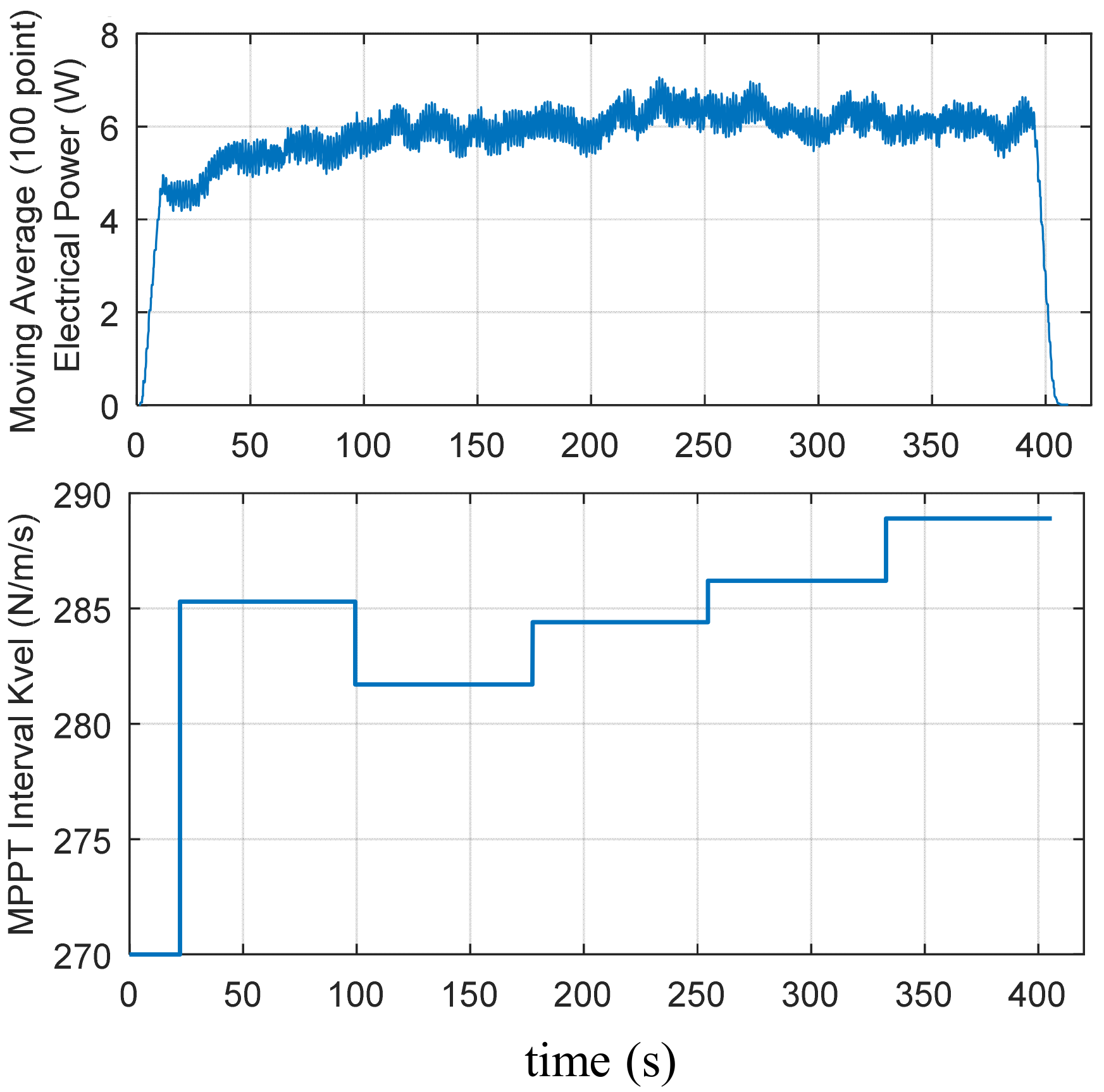
5.6. Automated Control and Transient Results
6. Conclusions
Author Contributions
Funding
Acknowledgments
Conflicts of Interest
References
- Aderinto, T.; Li, H. Review on Power Performance and Efficiency of Wave Energy Converters. Energies 2019, 12, 4329. [Google Scholar] [CrossRef] [Green Version]
- Aderinto, T.; Li, H. Ocean Wave Energy Converters: Status and Challenges. Energies 2018, 11, 1250. [Google Scholar] [CrossRef] [Green Version]
- Huang, L.; Hu, M.; Chen, Z.; Yu, H.; Liu, C. Research on a Direct-Drive Wave Energy Converter Using an Outer-PM Linear Tubular Generator. IEEE Trans. Magn. 2017, 53, 1–4. [Google Scholar] [CrossRef]
- Ivanova, I.; Agren, O.; Bernhoff, H.; Leijon, M. Simulation of wave-energy converter with octagonal linear generator. IEEE J. Ocean. Eng. 2005, 30, 619–629. [Google Scholar] [CrossRef]
- Wahyudie, A.; Jama, M.; Susilo, T.B.; Mon, B.F.; Shaaref, H.; Noura, H. Design and testing of a laboratory scale test rig for wave energy converters using a double-sided permanent magnet linear generator. IET Renew. Power Gener. 2017, 11, 922–930. [Google Scholar] [CrossRef]
- Farrok, O.; Islam, M.R.; Sheikh, M.R.I.; Guo, Y.G.; Zhu, J.G. Design and Analysis of a Novel Lightweight Translator Permanent Magnet Linear Generator for Oceanic Wave Energy Conversion. IEEE Trans. Magn. 2017, 53, 1–4. [Google Scholar] [CrossRef] [Green Version]
- Corpower. Available online: https://www.corpowerocean.com/ (accessed on 11 June 2022).
- Yemm, R.; Pizer, D.; Retzler, C.; Henderson, R. Pelamis: Experience from concept to connection. Philos. Trans. R. Soc. A Math. Phys. Eng. Sci. 2012, 370, 365–380. [Google Scholar] [CrossRef] [Green Version]
- Carnegie. 20 December 2021. Available online: https://www.carnegiece.com/ (accessed on 11 June 2022).
- Wello Wave Energy. Available online: https://wello.eu/ (accessed on 11 June 2022).
- Henderson, R. Design, simulation, and testing of a novel hydraulic power take-off system for the Pelamis wave energy converter. Renew. Energy 2006, 31, 271–283. [Google Scholar] [CrossRef]
- Cameron, L.; Doherty, R.; Henry, A.; Doherty, K.; Van’t Hoff, J.; Kaye, D.; Naylor, D.; Bourdier, S.; Whittaker, T. Design of the Next Generation of the Oyster Wave Energy Converter. In Proceedings of the 3rd International Conference on Ocean Energy, Bilbao, Spain, 6–9 October 2010; Volume 6, p. 1e12. [Google Scholar]
- Wang, Y.-L. A wave energy converter with magnetic gear. Ocean Eng. 2015, 101, 101–108. [Google Scholar] [CrossRef]
- Calado, M.D.R.; Godinho, P.M.C.; Mariano, S.J.P.S. Design of a new linear generator for wave energy conversion based on analytical and numerical analyses. J. Renew. Sustain. Energy 2012, 4, 033117. [Google Scholar] [CrossRef]
- Watanabe, R.; Shin, J.-S.; Koseki, T.; Kim, H.-J. Optimal Design for High Output Power of Transverse-Flux-Type Cylindrical Linear Synchronous Generator. IEEE Trans. Magn. 2014, 50, 1–4. [Google Scholar] [CrossRef]
- García-Tabarés, L.; Lafoz, M.; Blanco, M.; Torres, J.; Obradors, D.; Nájera, J.; Navarro, G.; García, F.; Sánchez, A. New type of linear switched reluctance generator for wave energy applications. IEEE Trans. Appl. Supercond. 2020, 30, 1–5. [Google Scholar] [CrossRef]
- Cappelli, L.; Marignetti, F.; Mattiazzo, G.; Giorcelli, E.; Bracco, G.; Carbone, S.; Attaianese, C. Linear Tubular Permanent-Magnet Generators for the Inertial Sea Wave Energy Converter. IEEE Trans. Ind. Appl. 2013, 50, 1817–1828. [Google Scholar] [CrossRef]
- Curto, D.; Franzitta, V.; Guercio, A.; Miceli, R.; Nevoloso, C.; Raimondi, F.M.; Trapanese, M. An Experimental Comparison between an Ironless and a Traditional Permanent Magnet Linear Generator for Wave Energy Conversion. Energies 2022, 15, 2387. [Google Scholar] [CrossRef]
- Krishna, R.; Svensson, O.; Rahm, M.; Kottayil, S.K.; Waters, R.; Leijon, M. Analysis of linear wave power generator model with real sea experimental results. IET Renew. Power Gener. 2013, 7, 574–581. [Google Scholar] [CrossRef]
- Lejerskog, E.; Strömstedt, E.; Savin, A.; Boström, C.; Leijon, M. Study of the operation characteristics of a point absorbing direct driven permanent magnet linear generator deployed in the Baltic Sea. IET Renew. Power Gener. 2016, 10, 1204–1210. [Google Scholar] [CrossRef] [Green Version]
- Polinder, H.; Damen, M.; Gardner, F. Linear PM Generator System for Wave Energy Conversion in the AWS. IEEE Trans. Energy Convers. 2004, 19, 583–589. [Google Scholar] [CrossRef] [Green Version]
- García-Violini, D.; Faedo, N.; Jaramillo-Lopez, F.; Ringwood, J.V. Simple Controllers for Wave Energy Devices Compared. J. Mar. Sci. Eng. 2020, 8, 793. [Google Scholar] [CrossRef]
- Seo, S.-W.; Shin, K.-H.; Koo, M.-M.; Hong, K.; Yoon, I.-J.; Choi, J.-Y. Experimentally Verifying the Generation Characteristics of a Double-Sided Linear Permanent Magnet Synchronous Generator for Ocean Wave Energy Conversion. IEEE Trans. Appl. Supercond. 2020, 30, 1–4. [Google Scholar] [CrossRef]
- Baker, N.J.; Almoraya, A.; Raihan, M.A.H.; McDonald, S.; Pickert, V. Electric Drive Train Design for Wave Energy Converters. In Proceedings of the 2019 12th International Symposium on Linear Drives for Industry Applications (LDIA), Neuchatel, Switzerland, 1–3 July 2019; pp. 1–6. [Google Scholar]
- Baker, N.; McNabb, L.; McDonald, S.; Almoraya, A. Development and Testing of A Small Scale Wave Energy Converter and Fully Controlled Linear Electric Generator. In Proceedings of the 10th International Conference on Power Electronics, Machines and Drives (PEMD 2020), Dubrovnik, Croatia, 22–24 September 2021; pp. 308–313. [Google Scholar] [CrossRef]
- Prudell, J.; Stoddard, M.; Amon, E.; Brekken, T.K.A.; Von Jouanne, A. A Permanent-Magnet Tubular Linear Generator for Ocean Wave Energy Conversion. IEEE Trans. Ind. Appl. 2010, 46, 2392–2400. [Google Scholar] [CrossRef]
- Shek, J.; Macpherson, D.; Mueller, M.; Xiang, J. Reaction force control of a linear electrical generator for direct drive wave energy conversion. IET Renew. Power Gener. 2007, 1, 17–24. [Google Scholar] [CrossRef] [Green Version]
- Sergiienko, N.; Cazzolato, B.; Ding, B.; Hardy, P.; Arjomandi, M. Performance comparison of the floating and fully submerged quasi-point absorber wave energy converters. Renew. Energy 2017, 108, 425–437. [Google Scholar] [CrossRef] [Green Version]
- Kovaltchouk, T.; Blavette, A.; Aubry, J.; Ahmed, H.B.; Multon, B. Comparison Between Centralized and Decentralized Storage Energy Management for Direct Wave Energy Converter Farm. IEEE Trans. Energy Convers. 2016, 31, 1051–1058. [Google Scholar] [CrossRef] [Green Version]
- Garcia-Tabares, L.; Hernando, C.; Munilla, J.; Torres, J.J.; Santos-Herran, M.; Blanco, M.; Sanz, S.; Sarmiento, G.; Lorenzo, F.G.; Neri, M.; et al. Concept Design of a Novel Superconducting PTO Actuator for Wave Energy Extraction. IEEE Trans. Appl. Supercond. 2022, 32, 1–5. [Google Scholar] [CrossRef]
- Keysan, O.; Mueller, M. A Linear Superconducting Generator for Wave Energy Converters. In Proceedings of the 6th IET International Conference on Power Electronics, Machines and Drives (PEMD 2012), Bristol, UK, 27–29 March 2012. [Google Scholar] [CrossRef]
- Spooner, E.; Haydock, L. Vernier hybrid machines. IEE Proc. Electr. Power Appl. 2003, 150, 655–662. [Google Scholar] [CrossRef]
- Raihan, M.A.H.; Baker, N.J.; Smith, K.J.; Almoraya, A.A. An E-Core Linear Veriner Hybrid Permanent Magnet Machine with Segmented Translator for Direct Drive Wave Energy Converter. In Proceedings of the 2017 IEEE International Electric Machines and Drives Conference (IEMDC), Miami, FL, USA, 21–24 May 2017; pp. 1–6. [Google Scholar] [CrossRef]
- Mueller, M.; Baker, N. Modelling the performance of the vernier hybrid machine. IEE Proc. Electr. Power Appl. 2003, 150, 647–654. [Google Scholar] [CrossRef]
- Baker, N.J.; Raihan, M.A.H.; Almoraya, A.A.; Burchell, J.; Mueller, M.A. Evaluating Alternative Linear Vernier Hybrid Machine Topologies for Integration Into Wave Energy Converters. IEEE Trans. Energy Convers. 2018, 33, 2007–2017. [Google Scholar] [CrossRef] [Green Version]
- Almoraya, A.A.; Baker, N.J.; Smith, K.J.; Raihan, M.A.H. Design and Analysis of a Flux-Concentrated Linear Vernier Hybrid Machine With Consequent Poles. IEEE Trans. Ind. Appl. 2019, 55, 4595–4604. [Google Scholar] [CrossRef] [Green Version]
- Baker, N.J.; Raihan, M.A.H.; Almoraya, A.A. A Cylindrical Linear Permanent Magnet Vernier Hybrid Machine for Wave Energy. IEEE Trans. Energy Convers. 2018, 34, 691–700. [Google Scholar] [CrossRef] [Green Version]
- Li, D.; Qu, R.; Li, J.; Xu, W. Consequent-Pole Toroidal-Winding Outer-Rotor Vernier Permanent-Magnet Machines. IEEE Trans. Ind. Appl. 2015, 51, 4470–4481. [Google Scholar] [CrossRef]
- Raihan, M.A.H.; Baker, N.J.; Smith, K.J.; Almoraya, A.A. Development and Performance Analysis of a Double Sided Linear Hybrid Reluctance PM Machine for Low Speed Applications. In Proceedings of the International Conference on Power Electronics Machines and Drives, Liverpool, UK, 17–19 April 2018; pp. 1–6. [Google Scholar]
- Raihan, M.; Baker, N.; Smith, K.; Almoraya, A. Development and Testing of a Novel Cylindrical Permanent Magnet Linear Generator. IEEE Trans. Ind. Appl. 2020, 56, 3668–3678. [Google Scholar] [CrossRef]
- Hodgins, N.; Keysan, O.; McDonald, A.; Mueller, M. Linear generator for direct drive wave energy applications. In Proceedings of the XIX International Conference on Electrical Machines-ICEM, Rome, Italy, 6–8 September 2010; pp. 1–6. [Google Scholar]
- Hodgins, N.; Keysan, O.; McDonald, A.; Mueller, M.A. Design and Testing of a Linear Generator for Wave-Energy Applications. IEEE Trans. Ind. Electron. 2011, 59, 2094–2103. [Google Scholar] [CrossRef]
- McDonald, S.P.; Baker, N.J.; Espinoza, M.; Pickert, V. Power-Take-Off Topology Comparison for a Wave Energy Converter. J. Eng. 2019, 2019, 5012–5017. [Google Scholar] [CrossRef]
- McDonald, S.P.; Baker, N.J.; Pickert, V. High-frequency current source converter for a direct drive powertrain in a wave energy converter. J. Eng. 2019, 2019, 3629–3633. [Google Scholar] [CrossRef]
- FloWave Ocean Energy Research Facility. Available online: https://www.flowavett.co.uk/ (accessed on 11 June 2022).
- Boyle, G. Renewable Energy Power for a Sustainable Future; Oxford University Press: Oxford, UK, 2004. [Google Scholar]
- Engström, J.; Eriksson, M.; Isberg, J.; Leijon, M. Wave energy converter with enhanced amplitude response at frequencies coinciding with Swedish west coast sea states by use of a supplementary submerged body. J. Appl. Phys. 2009, 106, 064512. [Google Scholar] [CrossRef] [Green Version]
- Lettenmaier, T.; von Jouanne, A.; Brekken, T. A new maximum power point tracking algorithm for ocean wave energy converters. Int. J. Mar. Energy 2017, 17, 40–55. [Google Scholar] [CrossRef] [Green Version]
- Lettenmaier, T.; Von Jouanne, A.; Amon, E.; Moran, S.; Gardiner, A. Testing the WET-NZ Wave Energy Converter Using the Ocean Sentinel Instrumentation Buoy. Mar. Technol. Soc. J. 2013, 47, 164–176. [Google Scholar] [CrossRef]
- Ding, B.; Cazzolato, B.S.; Arjomandi, M.; Hardy, P.; Mills, B. Sea-state based maximum power point tracking damping control of a fully submerged oscillating buoy. Ocean Eng. 2016, 126, 299–312. [Google Scholar] [CrossRef]
- Xiao, X.; Huang, X.; Kang, Q. A Hill-Climbing-Method-Based Maximum-Power-Point-Tracking Strategy for Direct-Drive Wave Energy Converters. IEEE Trans. Ind. Electron. 2015, 63, 257–267. [Google Scholar] [CrossRef]


| Topology | Component per Pole Pair | ||
|---|---|---|---|
| Magnet | Pole piece | total | |
| Surface Mount | 2 | 0 | 2 |
| Consequent Pole (CP) | 1 | 0 | 1 |
| V Shape | 4 | 2 | 6 |
| V-Shape CP | 2 | 1 | 3 |
| Halbach CP | 3 | 0 | 3 |
Publisher’s Note: MDPI stays neutral with regard to jurisdictional claims in published maps and institutional affiliations. |
© 2022 by the authors. Licensee MDPI, Basel, Switzerland. This article is an open access article distributed under the terms and conditions of the Creative Commons Attribution (CC BY) license (https://creativecommons.org/licenses/by/4.0/).
Share and Cite
Baker, N.J.; Almoraya, A.; Raihan, M.A.H.; McDonald, S.; McNabb, L. Development and Wave Tank Demonstration of a Fully Controlled Permanent Magnet Drive for a Heaving Wave Energy Converter. Energies 2022, 15, 4811. https://doi.org/10.3390/en15134811
Baker NJ, Almoraya A, Raihan MAH, McDonald S, McNabb L. Development and Wave Tank Demonstration of a Fully Controlled Permanent Magnet Drive for a Heaving Wave Energy Converter. Energies. 2022; 15(13):4811. https://doi.org/10.3390/en15134811
Chicago/Turabian StyleBaker, Nick J., Ahmed Almoraya, Mohammad A. H. Raihan, Steve McDonald, and Luke McNabb. 2022. "Development and Wave Tank Demonstration of a Fully Controlled Permanent Magnet Drive for a Heaving Wave Energy Converter" Energies 15, no. 13: 4811. https://doi.org/10.3390/en15134811
APA StyleBaker, N. J., Almoraya, A., Raihan, M. A. H., McDonald, S., & McNabb, L. (2022). Development and Wave Tank Demonstration of a Fully Controlled Permanent Magnet Drive for a Heaving Wave Energy Converter. Energies, 15(13), 4811. https://doi.org/10.3390/en15134811