Article

Experiment and Model of Conductivity Loss of Fracture Due to Fine-Grained Particle Migration and Proppant Embedment

1
School of Petroleum Engineering, China University of Petroleum (East China), Qingdao 266580, China
2
Key Laboratory of Unconventional Oil & Gas Development, China University of Petroleum (East China), Ministry of Education, Qingdao 266580, China
3
Shanghai Branch of China Petroleum Pipeline Engineering Corporation, Shanghai 200127, China
*
Author to whom correspondence should be addressed.
Energies 2022, 15(7), 2359; https://doi.org/10.3390/en15072359
Submission received: 24 January 2022 / Revised: 10 March 2022 / Accepted: 11 March 2022 / Published: 24 March 2022

Abstract

:
In weakly cemented reservoirs or coal-bed methane reservoirs, the conductivity of hydraulic fractures always declines after a period of production, which greatly influences gas production. In this paper, a comprehensive model considering fine-grained particle migration and proppant embedment is proposed to give a precise prediction for conductivity decline. Then, an experiment was conducted to simulate this process. A published experiment using coal fines was also tested and simulated. The results indicate that both fine-grained particle migration and proppant embedment have great negative effect on conductivity of fractures in weakly cemented sandstone and coal-bed methane reservoirs. The formulation we proposed matches the experimental data smoothly and can be widely used in the prediction of conductivity decline in weakly cemented sandstone and coal-bed methane reservoirs. In order to discuss the influencing factors of the filtration coefficient in the particle transport model, a porous media network model was established based on the theoretical model. The simulation results show that the filtration coefficient increases with the increase in particle size and/or throat size, and the filtration coefficient increases with the decrease in the fluid velocity. At the same time, it was found that the large larynx did not easily cause particle retention. Large size particles tend to cause particle retention.

1. Introduction

Hydraulic fracturing as an efficient way to stimulate production is widely used in various reservoirs and has achieved great success in the oil field. However, the production of fractured reservoirs always declines after a while, especially for weakly cemented reservoirs, which have been reported many times and have increasingly become the concern of researchers [1,2,3,4,5]. Many of the research regarding the permeability and fluid transport processes of shale point out that a number of factors influence fluid flow. One important reason is closure of the fractures, and another is fine-grained particle migration causing plugging, which only occurs in weakly cemented and coal-bed methane reservoirs [6,7,8,9]. However, many researchers only focus on conductivity loss caused by the closure of fractures that occur in shale or hard rock layers due to embedment. As for fine migration, few researchers study it [10,11,12].
Fine migration is of concern and has been studied for many years. Herzig et al. [13] proposed a model to simulate deep bed filtration and permeability decline in porous media based on mass conservation. Deposition, adsorption and straining are considered as the main mechanism of fine-grained particle retention. Bedrikovetsky et al. [14] used a deep bed filtration model to simulate fine-grained particle migration in an oil field and proposed a modified fine-grained particle migration formulation. Straining is thought to be the main mechanism in oil production causing a decline in permeability. Sharma and Yortsos [15] conducted an experiment to investigate formation damage and proposed formulas to simulate this process. Zou et al. [2] conducted experiments to simulate coal fine-grained particle migration in hydraulic fractures. The experimental results showed that coal fine-grained particle migration causes a significant decline in permeability. Zhang et al. [16] used an experiment to illustrate fine-grained particles and stress on permeability. However, the experiment was simple and the formulas did not consider all factors. While many of them are only related to transport in porous media, few focus on fracture proppant layer problems, which can also be the cause of potential damage to production.
As for proppant embedment, Tan et al. [17] experimentally investigated the effects of the layer number and type of proppant on fracture permeability. Zheng et al. [18] analyzed the special proppant distribution pattern of channel fracturing, and the expression of fracture permeability was derived. The effects of proppant distribution density and proppant pillar radius on fracture conductivity were analyzed. Although several effects were considered, fine-grained particle migration, especially on weakly cemented sandstone and coal-bed methane reservoirs should be analyzed.
As known to the petroleum industry, permeability is one of the most important factors to maintain economic production. Hydraulic fracturing has been widely used to introduce fractures with high permeability. However, the permeability of fractures in weakly cemented sandstone and coal-bed methane reservoirs decreases quickly after hydraulic fracturing [19]. Two potential factors, fine-grained particle migration and embedment, are usually considered solely due to the limits of experimental conditions. The investigation of embedment is usually in shale rock, and fine-grained particle migration is considered in formation with high-content clay. However, fractures in the weakly cemented layer can be a great situation to couple these two factors, which have not been fully discussed before. How to couple these two factors has been unviable in previous research. The motivation of our research is to identify the mechanism of fracture conductivity reduction due to proppant migration and embedment. Based on these understandings, the hydraulic fracturing parameters could be adjusted to maintain fracture conductivity for a longer time, which is also helpful to the reservoir protection and reliable production prediction.
In this paper, the imitation of a clay-like sparse sandstone core made in the Wenchang area, a comprehensive formula incorporating effects of closure pressure and fine-grained particle migration, was developed to simulate fracture conductivity loss. The Wenchang area is a medium-porosity and low-permeability reservoir with porosity ranging from 23.7% to 29.7% with an average of 26.9% and a permeability of 14.7 to 95.3 mD, averaging at 44.5 mD. The average Poisson’s ratio is 0.153–0.169, the average Young’s modulus of the rock is 150 MPa, the uniaxial compressive strength of the rock is 1.15–4.4 MPa, the formation fracturing pressure is 24–25 MPa, and the closure pressure of the fracture is about 16 MPa. The formula for the artificial core comprises quartz sand, clay mineral, water, and plagioclase, with a cementing ratio of 30:15:8:4:1, compression pressure of 12.5 MPa, and a loading rate of 100 N/s. Then, an experiment was conducted under proper conditions to validate this formula. Another experiment result by Zou et al. [2] was employed to validate the accuracy of formulation. Finally, a porous media network model was established based on the theoretical model to calculate the filtration coefficient and analyze its influencing factors.

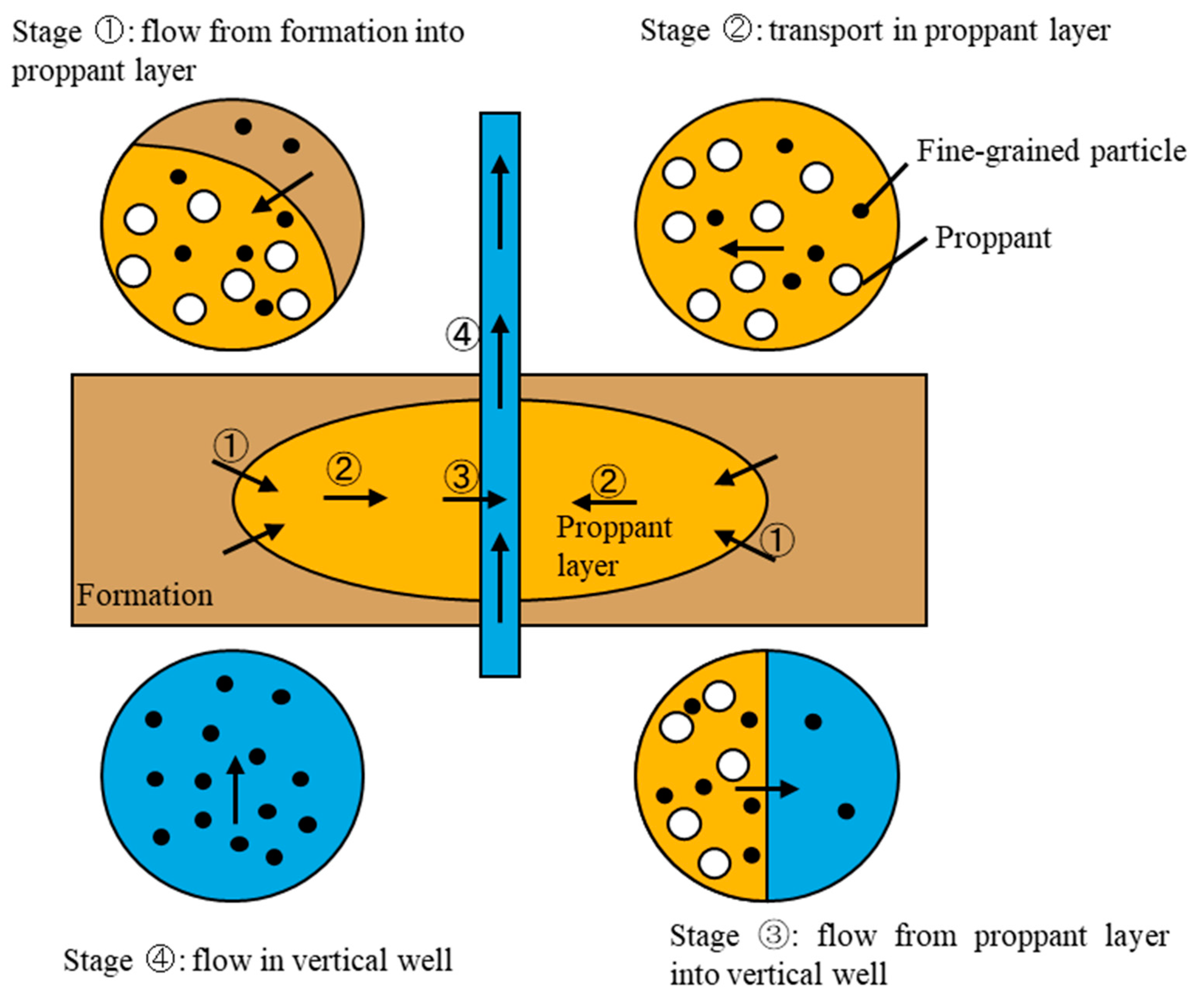
2. Fracture Conductivity Damage Model

Fine-grained particle generation, migration and deposition can be divided into four stages in the fractured layer, as shown in Figure 1. First, fine-grained particles are generated in the rock pore surface and are then rushed into the proppant layer. Second, fine-grained particles are transported to and are retained in the proppant layer. Third, suspended fine-grained particles flow into the vertical well from the proppant layer. Lastly, the mixture of fine-grained particles and oil flow into the vertical well. This article mainly focuses on the second stage, which can give a reasonable explanation for conductivity loss.

2.1. Fine-Grained Particle Migration Formulation

The equation describing fluid flow in porous media is shown below:
ϕ p t · [ k μ p ] = 0
where k is the permeability of proppant; ϕ is the porosity of the proppant layer; μ is the viscosity of the injected fluid, p is pressure, and t is time.
Suspension induced from the rock flow into the proppant layer and retention in this area both lead to a decline in permeability. Damage mechanisms of fine-grained particle migration have been reported in several previous studies in detail (e.g., [4,13]). However, in this situation, the attachment of particles to the surface of the proppant is mainly due to deposition and adsorption because fine-grained particles are smaller than the proppant throat. Thus, it is obvious that straining can be negligible. The equation describing fine-grained particle dispersion attachment in porous media based on the mass balance equation is derived as:
ϕ C t + σ t + · [ U C D C ] = 0
where D is the diffusion coefficient in m2/s; U is Darcy velocity in m/s; σ is the retention particle volume; C is the concentration of the suspension; ϕ is the porosity of the media.
Particle diffusion is negligible because the particle size in experiments is larger than one micrometer. Thus, D is equal to zero. A main mechanism of fine-grained particle retention is attachment [13]. The particle retention rate is a linear kinetics equation where the capture rate is proportional to particle flux CU:
σ t = λ C U

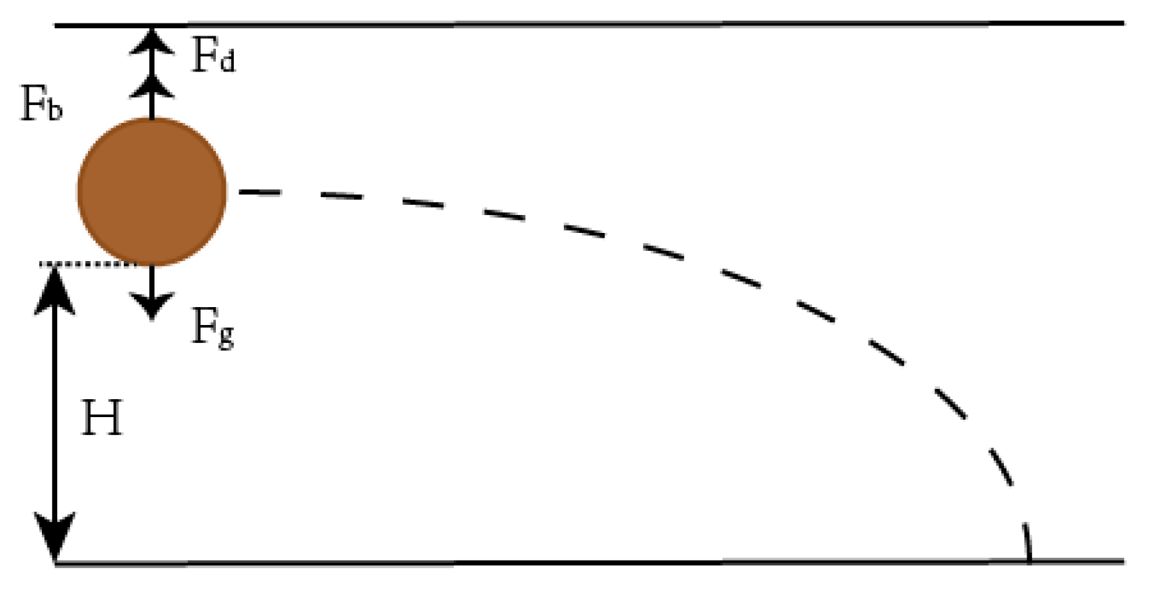
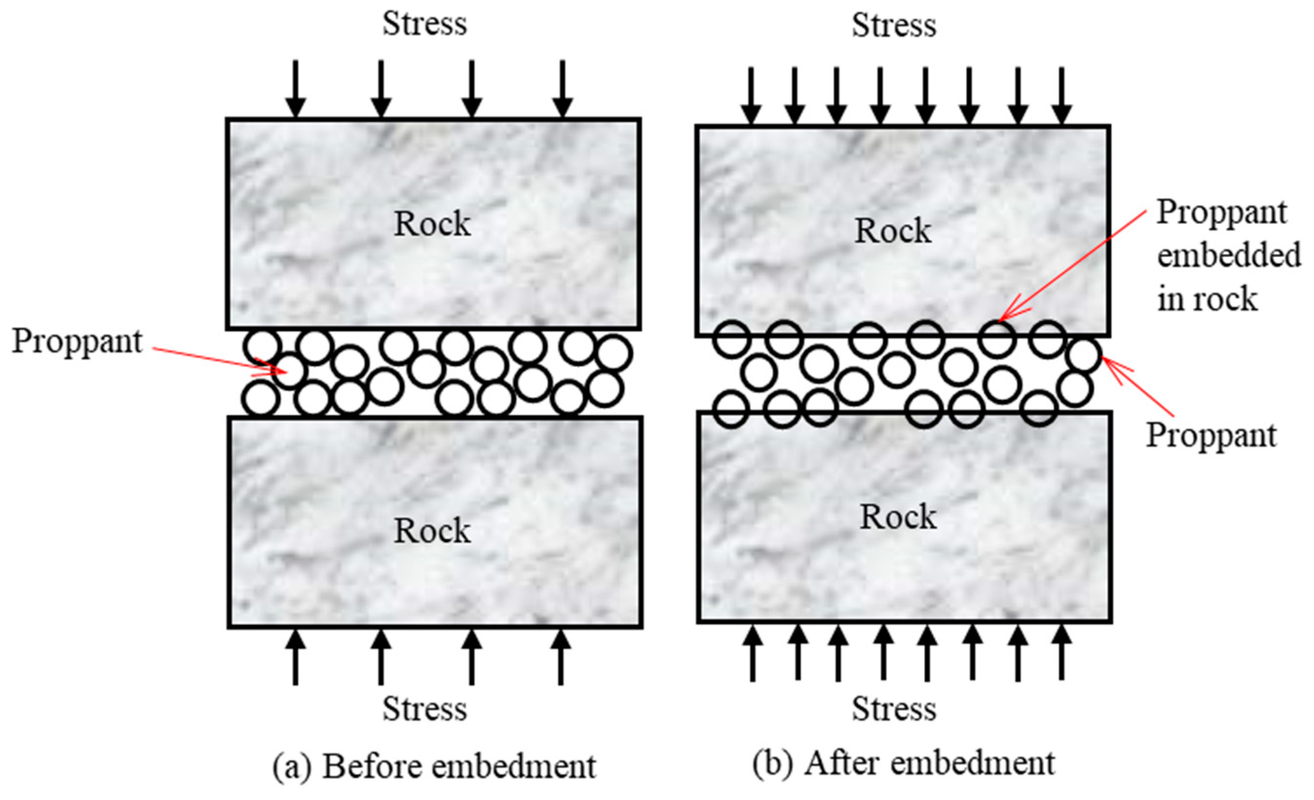
2.2. Embedment Formulation

During production, the permeability in hydraulic fractures can be generally attributed to two main effects (as shown in Figure 2): (i) the permeability reduction due to proppant pack compaction with the increase in closure stress; (ii) the permeability decrease induced by proppant embedment, which reduces the fracture aperture [20]. The total hydraulic permeability change is the combined effect of the two factors mentioned above. The model describing hydraulic fracture permeability under the combined effect of compaction and embedment is shown below [21]:
k p = k p 0 · e 3 c p ¯ ( σ e σ e 0 ) · ( b 0 η ( σ e ) λ ) 3 b 0 3
where c p ¯ is the average proppant pack compressibility; σe is the effective stress; σe0 is the initial effective stress; b0 is the fracture aperture before embedment; β and λ are fitting parameters from the experiment [21].
c p ¯ = c p 0 α ( σ e σ e 0 ) ( 1 e α ( σ e σ e 0 ) )
where α is the changing rate of the proppant pack compressibility; cp0 is the initial proppant compressibility.

2.3. Permeability Decline

Following former research (e.g., [22]), the inverse to normalized permeability k k 0 is a linear function of the retained particle.
k = k 0 1 + β · σ ( t )
where β is the formation damage coefficient; k is the permeability of the proppant layer in mD; k0 is the initial permeability in mD.
The model describing the hydraulic fracture conductivity is below:
c t o t a l = k · b 0
where c is the conductivity of fracture.

2.4. Boundary Condition and Solution

The shape of the container is shown in Figure 3. The inlet is the Dirichlet boundary ( k μ ) ( p μ ) = q π r 2 . The outlet is the Neumann boundary, P ( x , y , t ) = P o u t . The initial condition is P ( x , y , t = 0 ) = 0 . The commercial software COMSOL is employed here to solve the equation by the finite element method [23].

3. Experiments on Fracture Conductivity Damage

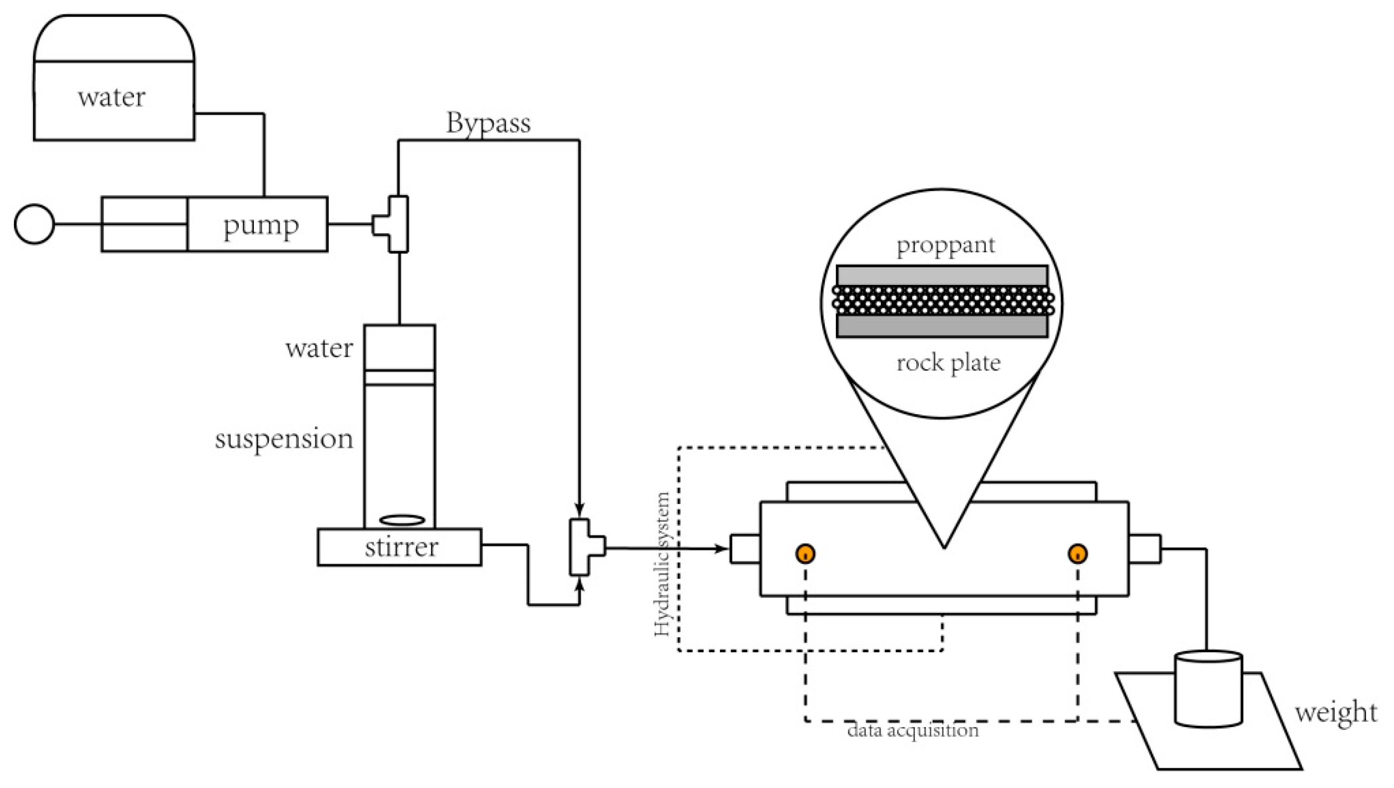
3.1. Experiment Procedure

The experimental apparatuses used in this paper are shown in Figure 3. Weakly cemented rock plates used in this experiment were made in the lab to simulate the real underground rock condition. Rock plates were made under great pressure, consisting of 6% montmorillonite, 8% plagioclase, 24% illite and 60% quartz sand. Different cement contents were added onto the rock plates to produce different kinds of rock mechanical properties. A higher cement content means a stronger bond between particles.
Fracture width, pressure difference and flow rate were measured by sensors, including a pressure difference sensor, pressure sensor, and displacement sensor. The pressure difference sensor was used to measure the inlet pressure, and the pressure sensor was used to measure the pressure loaded by the press, with a measurement accuracy of 1 MPa. The displacement sensor was used to measure the width of the joint with an accuracy of 0.01 mm. The flow rate of the fluid was measured by an electronic balance at the outlet, with an accuracy of 0.1 mL/min.
The experimental procedure is as follows:
(i)
The conductivity cell was paved with proppant. The fine-grained particles were mixed with water in an intermediate container with a stirrer at the bottom of the container, which kept the suspension stable. Two slices of rock plates were used to simulate a real rock fracture.
(ii)
The desired closure pressure was applied to the plates using a hydraulic pump. The constant-flux pumps were then push-pistoned inside the intermediate container to draw the suspension into the conductivity cell.
(iii)
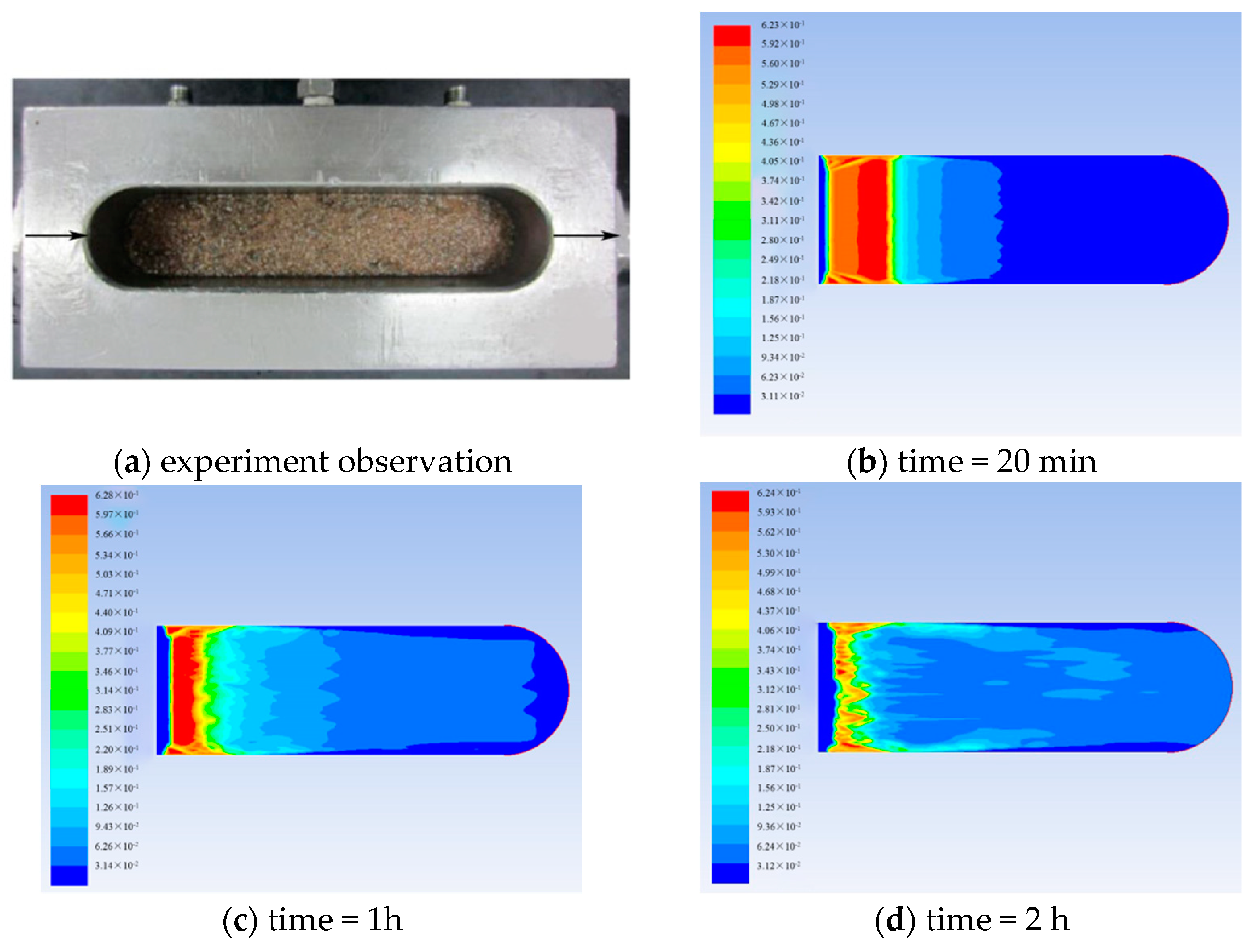
After a period, the pressure drop between the front and end of the cell was gauged. The distribution of the coal fine-grained particles in the proppant pack was then observed. The experimental data were analyzed.

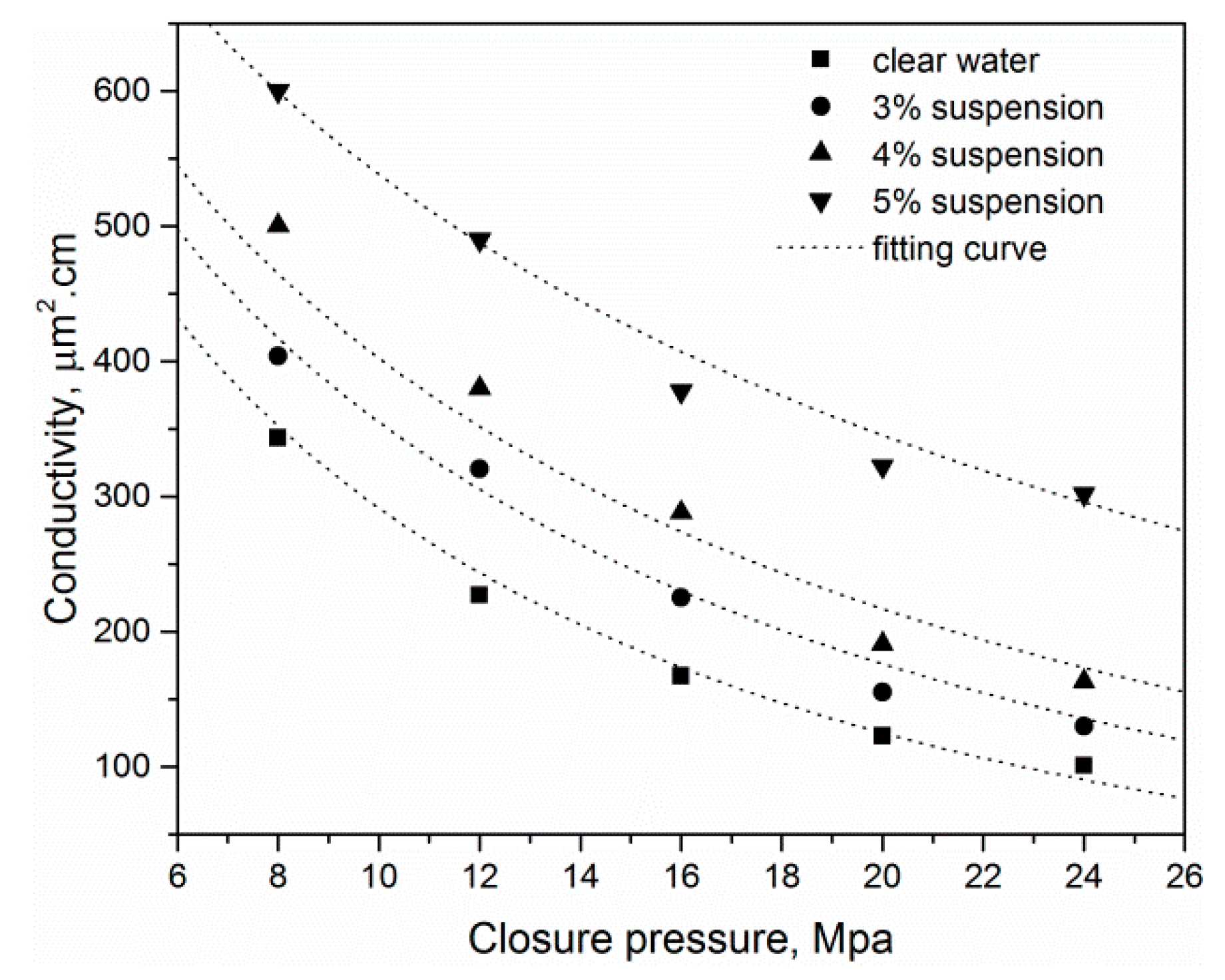
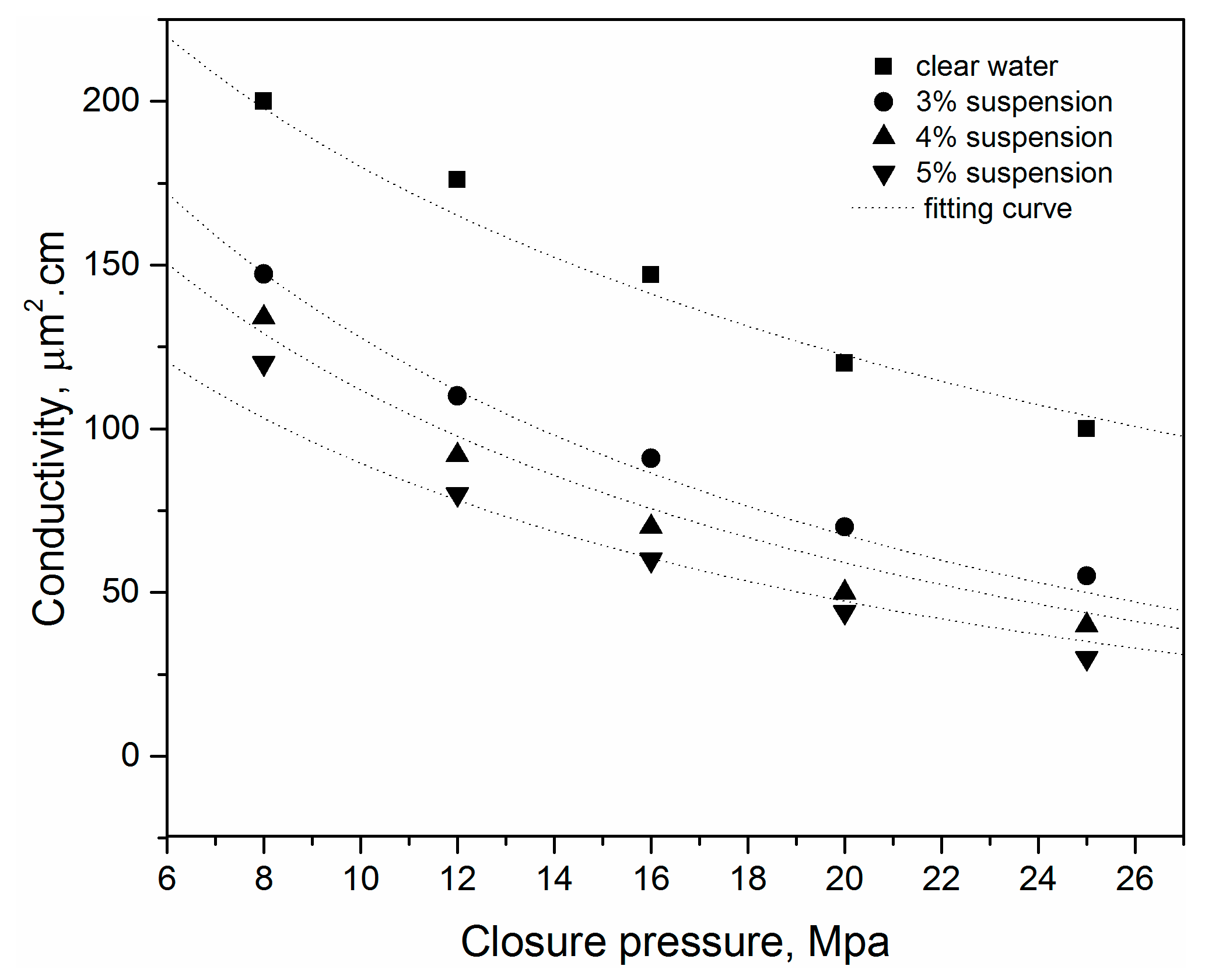
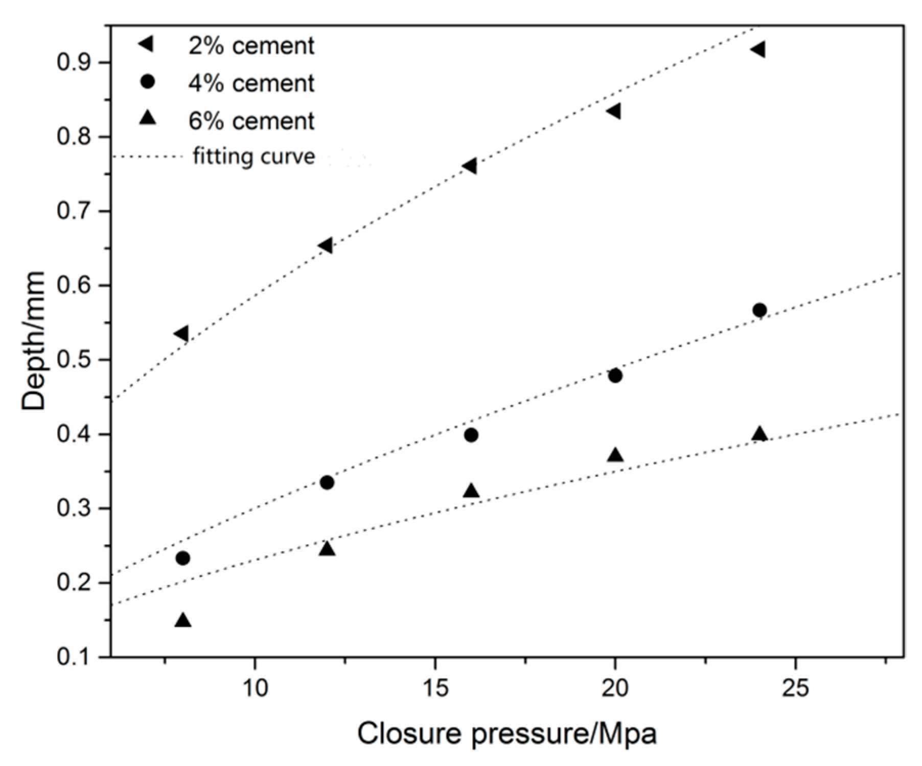
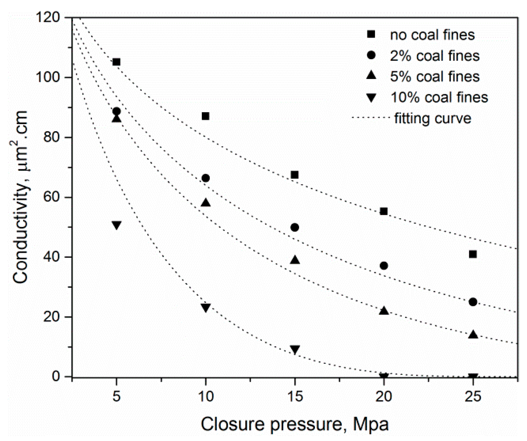
3.2. Result and Discussion

In this section, the results of the conductivity change, due to the fine-grained particle migration and embedment, are displayed. Then, we applied our model to analyze the results and examine model capacity. In the experiments, it was estimated that the injection was at a constant flow rate. The basic parameters of the experiment materials and coefficients are listed in Table 1.
Figure 4 shows the depth of the proppant embedment into the rock plate as a function of different tested closure pressures. The proppant embedment depth increases as the closure pressure increases. When the closure pressure is low, the slope of the embedment depth is large, indicating that it is easier to embed at a low embedding depth. When the closure pressure is high, the slope decreases, indicating that it is not easy to embed under high closure pressure. This is due to the fact that the contact area between the slab and the proppant particles increases with the loading as the embedment depth increases, which disperses the contact pressure and makes the proppant embedment more difficult than at lower contact areas. The depth increases steadily as a function of the closure pressure and reaches one millimeter when the closure pressure is 24 MPa. Conversely, the cement content represents a consolidated extent that reflects the strength of the rock. The proppant embedment depth decreases as the cement content increases. This is mainly reflected in the elastic modulus of the rock. The high content of cement leads to a large elastic modulus; thus, the embedding depth decreases. The fitting parameter λ corresponding to 2%, 4%, 6% cement contents are 0.015, 0.025, and 0.032, and the fitting parameter η corresponding to different cements are 0.65, 0.72, and 0.518.
Moreover, the change of conductivity with pressure is shown in Figure 5. With an increase in closure pressure, conductivity declines dramatically in an exponential trend. This is consistent with the results of [17].
A series of fine-grained particle migration experiments was performed at concentrations of 3%, 4% and 5% when the closure pressure increases from 8 to 25 MPa. The effects of the concentration and closure pressure on conductivity damage is presented in Figure 6, in which conductivity decreases with an increase in closure pressure. As the concentration increases, conductivity decreases. Conductivity declines as the concentration of the suspension increases because of a higher retention under higher concentrations. However, under high closure pressure, it can be seen that the conductivity of 3% and 4% concentrations decreases and gradually shrinks. Similarly, the difference between 4% and 5% concentrations shows that the influence of concentration becomes insignificant with the increase in closure pressure, which means that the difference of conductivity between different concentrations becomes less significant. This is due to the fact that when the closing pressure increases, the effect of the decrease in conductivity due to embedding is proportionally larger than that of the concentration. It can be predicted that when the closure pressure reaches a certain degree, the fracture conductivity has little relation with the concentration.
The effects of flow rate on fine-grained particle deposits and conductivity damage are shown in Figure 7. By injecting 3%, 4% and 5% suspension into the conductivity cell and by altering the flow rate from 3 to 10 mL/min, conductivity decreases significantly as flow rate is enhanced. In the case of a low flow rate, the conductivity with flow rate slope is larger, indicating that the permeability decreases sharply in the presence of particles in the proppant. As the flow rate increases, the slope tends to flatten. At the same time, the difference between the different concentrations remains roughly constant. A high flow rate means that many more particles flow into the porous media simultaneously and many more fine-grained particles are retained in the proppant pack.

3.3. Experiment Comparison with Published Data

Here, we cite the experiments conducted by Zou et al. [2], coal fines were used as migration fines to study conductivity decline as a function of fine migration and embedment. A series of coal fines migration experiments was performed using 212–425 µm sand at concentrations of 5 kg/m2, coal fines concentrations of 2%, 5%, or 10%, and 2 wt% KCl brine serving as carrier media. The conductivity was then measured under closure pressure ranging from 5 to 25 MPa. The experiment container size is similar to our set-up above. The basic parameters of the experiment materials and coefficients are listed in Table 2.
Rock plates were not employed in this experiment; thus, embedment is ignored and only compression is considered. Coal fines were lain on the container instead of being injected with fluid. Once the injection rate of the clean water was higher than the critical velocity, the coal fines could be lifted up and migrated into the proppant layer [24]. Fine-grained particle distribution in the container after two hours is shown in Figure 8a. A simulation of this process is displayed in Figure 8b–d.
Conductivity behaviors as a function of closure pressure and concentration are displayed in Figure 9. The decrease in conductivity is caused by the combined effects of clogging and the embedment of fine-grained particles as described above.
With the same concentration of coal fines, the conductivity decreases with an increase in closure pressure. The higher the concentration, the faster the decline rate of the conductivity. When the concentration of the coal fines is 10% and the closure pressure reaches 25 MPa, the conductivity is almost zero.

4. Filtration Coefficient of Particle Transport

Generally, a microscopic model is used to simulate the filtration coefficient, which is difficult to obtain experimentally. The advantages and disadvantages of each model are shown in Table 3.

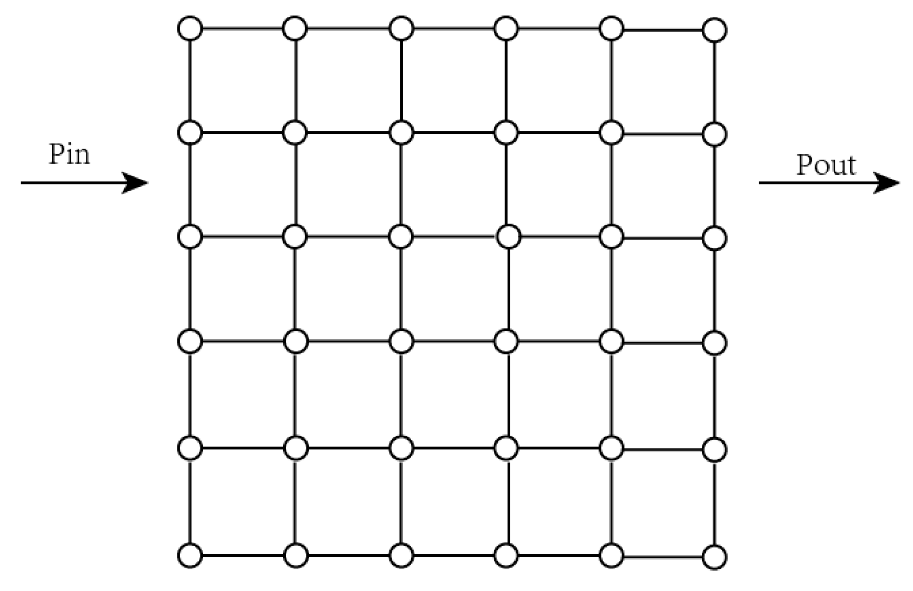
4.1. Development of Network Model

Through the model comparisons in Table 3, the network model is selected in this paper. The network model is a simplification of the porous media model, which uses a geometric network to replace the complex spatial structure in porous media and consists of relatively large pores and throats connecting the pores. In order to make the network model closer to the real core, the main characteristic parameters are the pore throat size, coordination number, and shape factor.
The pore throat size:
r = ( r max r min ) { δ ln [ x ( 1 e 1 / δ ) + e 1 / δ ] } 1 / γ + r min
where rmax and rmin represent the maximum and minimum size of the throat in m; δ is the truncated Weibull distribution constant, which is dimensionless; x represents a random number between 0 and 1.
Coordination number: The average coordination number of all pores in a porous medium is called the core coordination number. The larger the coordination number, the better the pore throat connectivity and the more complex the fluid flow in the porous media.
Shape factor:
G = A / P 2
where A is the cross-sectional area of pores; P represents the circumference of the pore throat section in m.

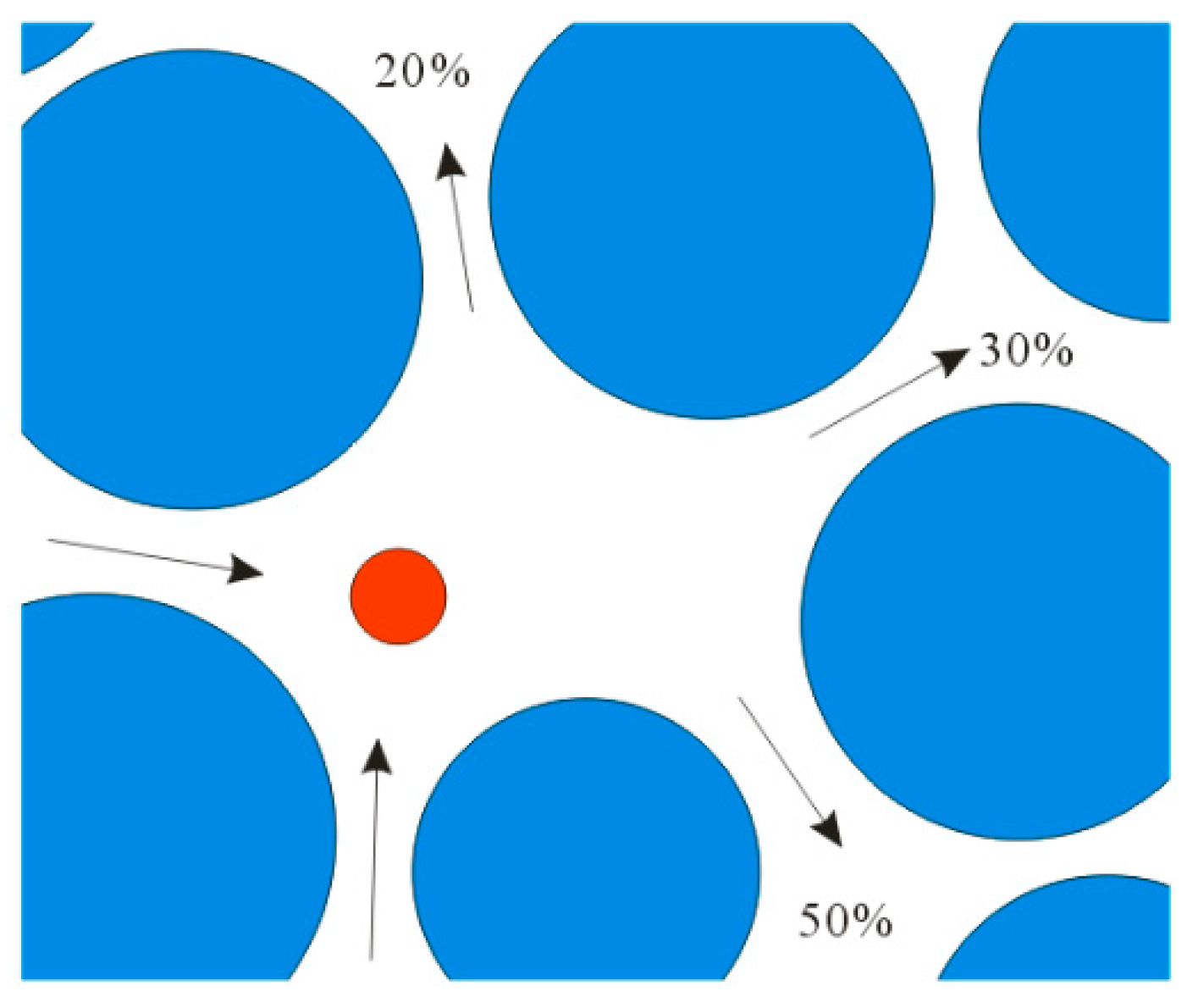
4.1.1. Particle Motion

Figure 10 is a schematic diagram of the force on the particles in the throat, in which gravity (Fg) on the particles in the fluid and the resultant van der Waals forces (Fb) on the top and ground of the particles are represented, in which viscous resistance (Fd) on the particles when they move along the Y-axis are represented [25].
Based on the force analysis in the y-direction, we obtain:
F b + F g F d = ρ p · V p · d u y d t
where uy is the velocity in the y-direction of the particle in m/s; ρp is the density of the particle in kg/m3; Vp is the volume of the particles in m3. Assuming that the particle is at the middle part of the throat when the particles enter the throat, we obtain:
u y = ( F A ( l R y ) + F g F A ( l + R + y ) ) D c
where Dc is the viscous resistance coefficient.

4.1.2. Fluid Flow

The network model uses regularly shaped pipes to replace the throats and considers these regular pipes as capillaries; thus, the fluid flow in the pore throat is in accordance with the Poiseuille formula [19,26].
Conductivity is introduced to calculate the pressure at the pore throat:
g = k A 2 G μ L = 1 2 A 2 G μ L
where A represents the pore throat section area; G represents the shape factor, in which circular pipes can generally be regarded as 1; μ represents the fluid viscosity; L represents the effective pipe length of the pore throat.
The sum of the inflow and outflow flows at each hole throat in the model is 0, namely:
j n q i j = 0
where, i is the pore; j represents the throat connected with the pore; n represents coordination number.
The flow rate between two adjacent orifice throats can be calculated by:
q i j = g i j ( p i p j )
where, gij is the conductivity of fluid between different orifices and throats.

4.1.3. Effective Radius

When particles are deposited in the throat, the flow field in the throat after deposition changes due to the presence of particles, and the changed flow field is calculated by effective radius. The effective radius is related to the original throat radius, throat length, particle radius and deposition location [27].
β = 1.6401 ( r R ) 4 + 1.1412 ( r R ) 3 0.6368 ( r R ) 2 0.0804 ( r R ) + 1
( r n e w r ) 4 = 1 23.33 ( 1 β ) · ( 1 x L ) R L
where, rnew is the throat radius after deposition, m; x denotes the length of the particle deposition position from the entrance, m; R represents the pore throat radius, m; L is the pore throat length, m.
Particles are released sequentially from the network model inlet. The motion trajectory of the particles is calculated by the force of the particles to determine whether they will be separated from the network model or deposited in the porous media. During pore migration, particles will move along the direction of high velocity in the throat path, and the velocity will be selected randomly at the same time. As shown in the Figure 11, when particles enter the pore throat, the throat with the 50% flow rate will be selected for the next calculation [28].
Based on the above calculation, the filtration coefficient can be calculated as [29,30,31]:
λ = n d n L
where λ is the filtration coefficient in m−1; nd denotes the number of particles remaining in the porous medium; n denotes the total number of particles passing through the porous medium; L represents the length of porous medium in m.

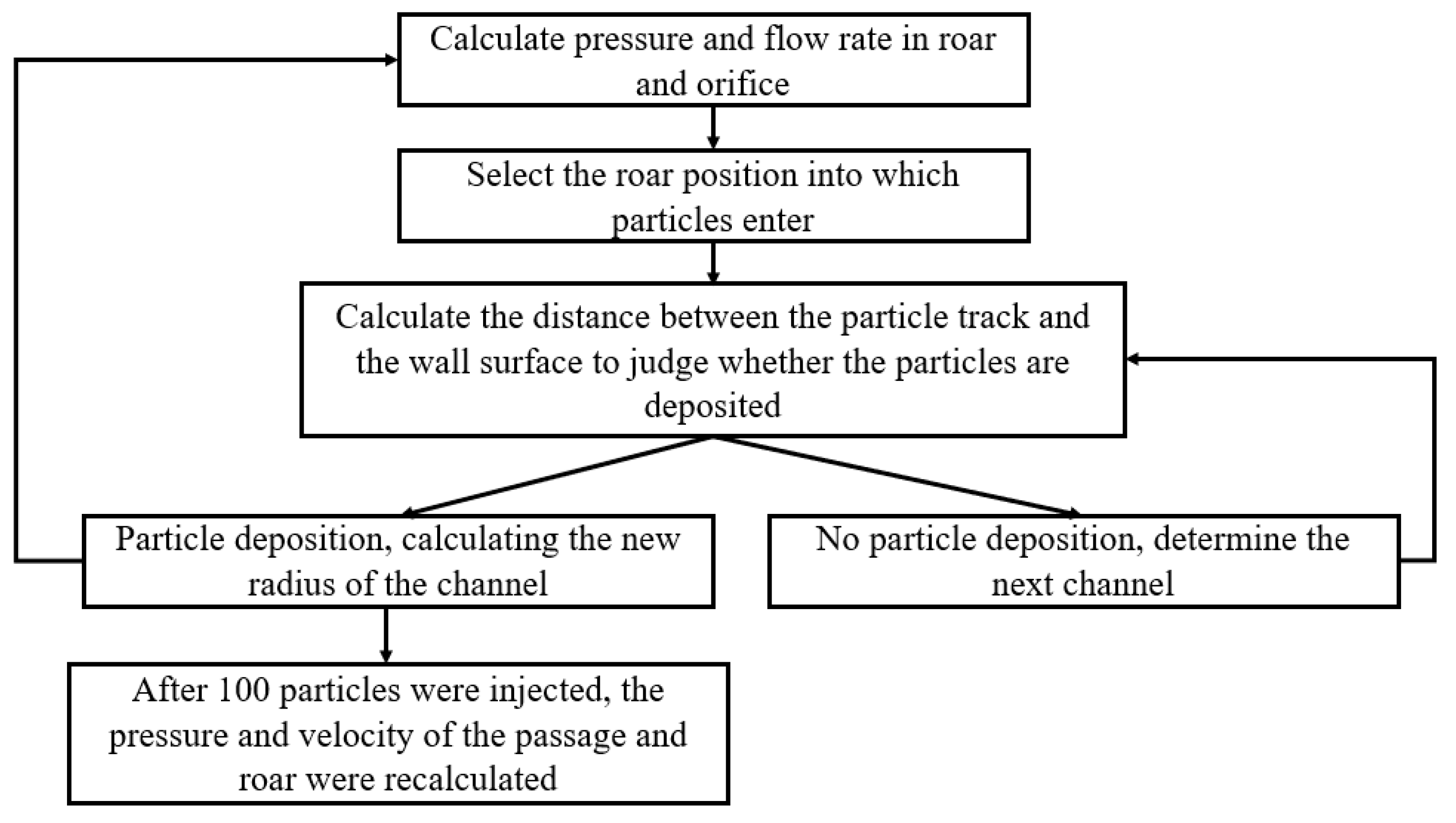
4.2. Calculation Process

The random network model is used to divide the mesh. The random network model only needs to randomly distribute the pores and throats in the regular mesh according to the pore throat statistics of the core and simplify the pore throat shape by using the regular geometry, so as to build the network model [19,32,33,34,35].
Due to the uniformity of the proppant size and regularity of the proppant shape, the selected network model can ignore the randomness of the pore throats, as shown in Figure 12. Through the establishment of the particle migration network model, the force and movement trajectory of the particle can be calculated. The calculation steps are shown in Figure 13. The values of the specific parameters are listed in Table 4.
The following are assumptions about the network model: (i) Only one particle can be placed into each operation, and the calculation of the next particle can only be carried out after the motion state of the former particle is determined. (ii) The random network model only needs to randomly distribute the pores and throats in a regular grid according to core pore–throat statistics. (iii) Regular geometry is used to simplify the shape of the pore throat, such as cylinders of circles, triangles and squares. (iv) Pipes with regular shapes regarded as capillaries are used to replace the throat.

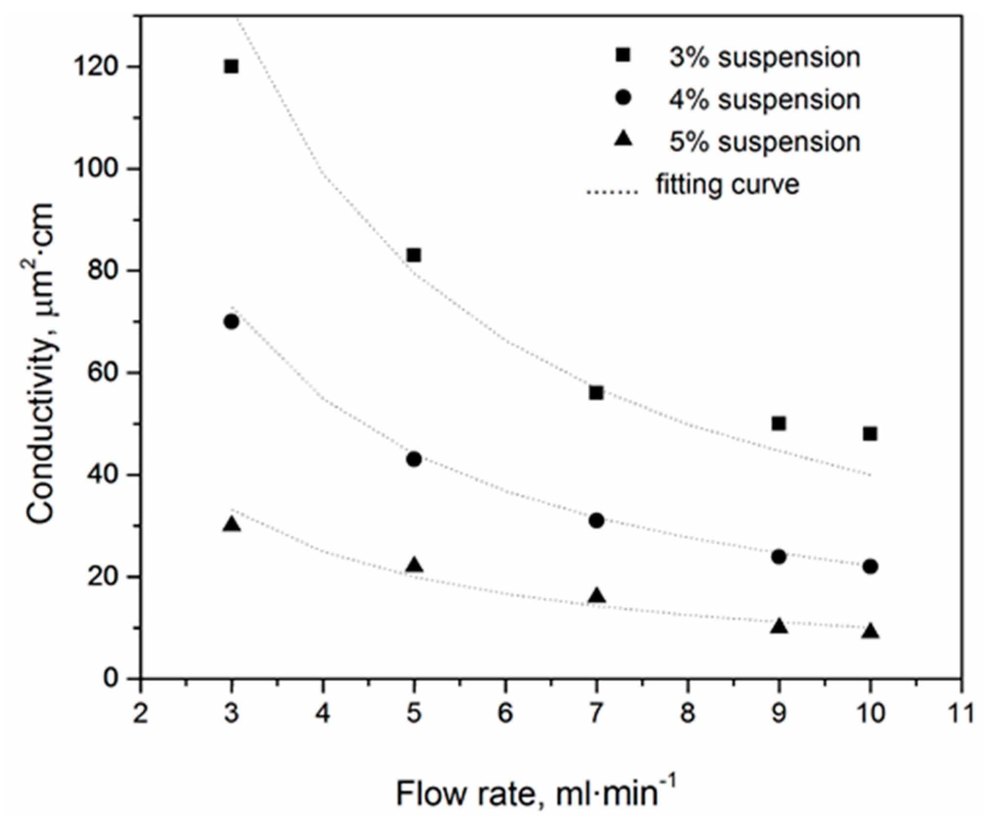
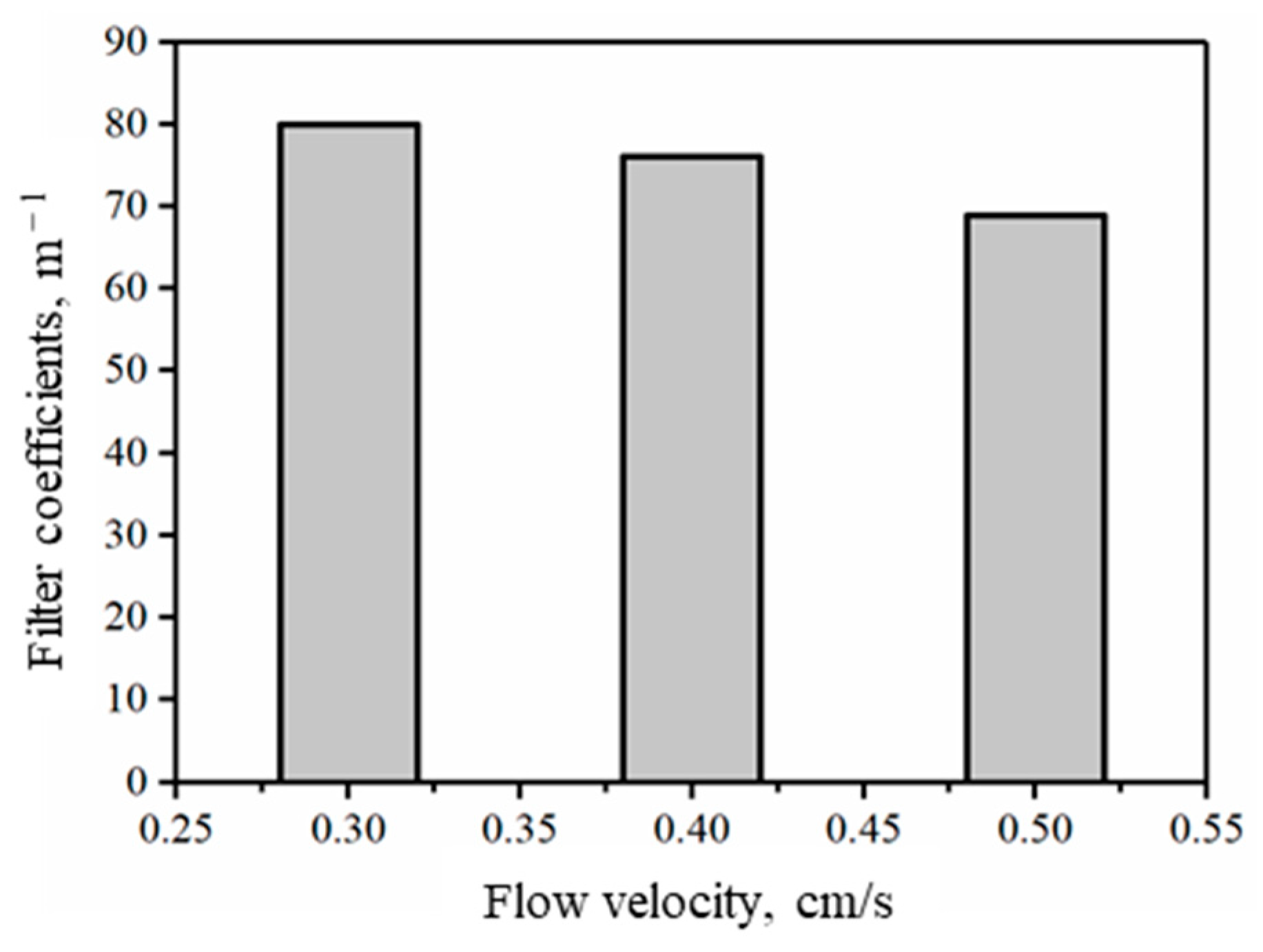
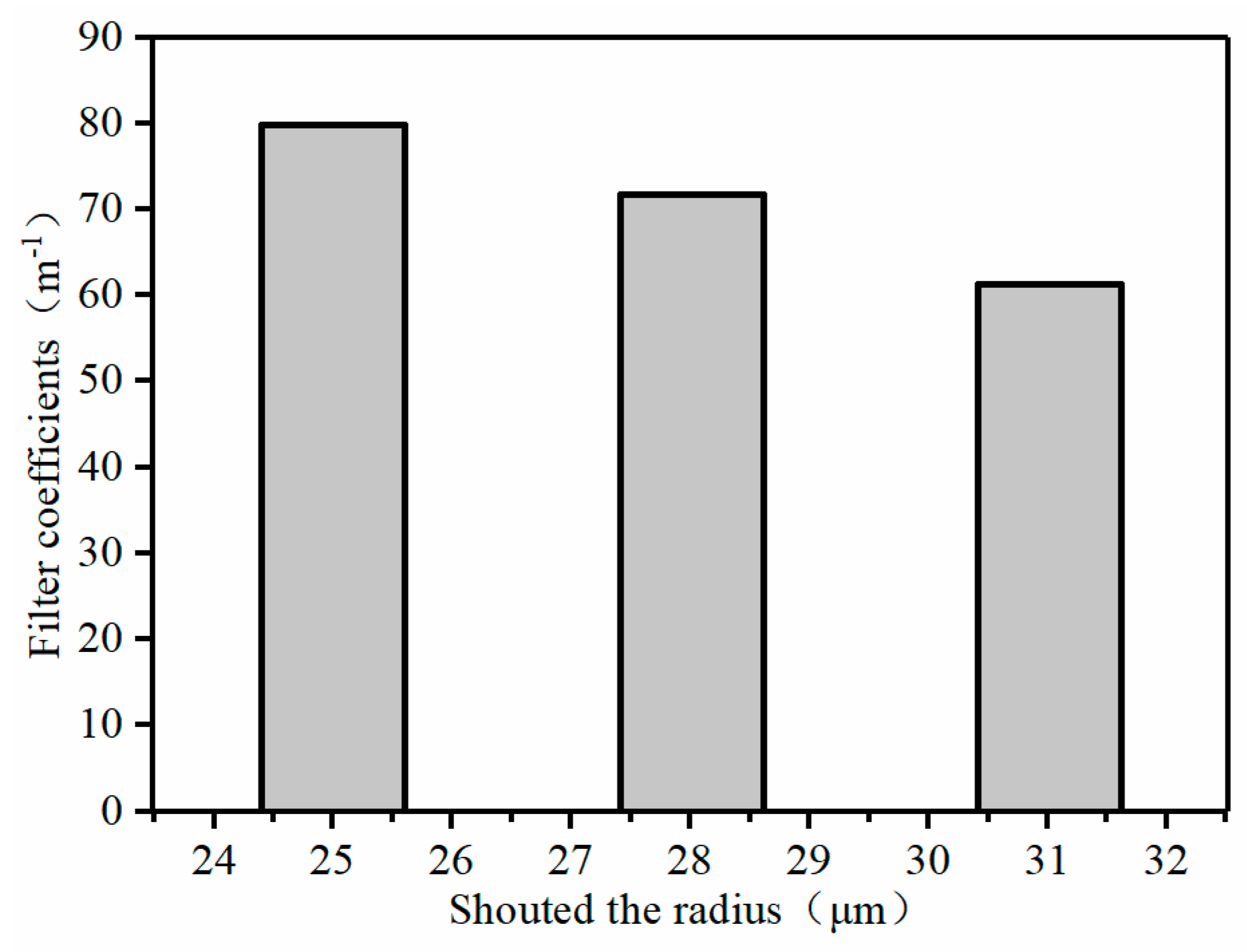
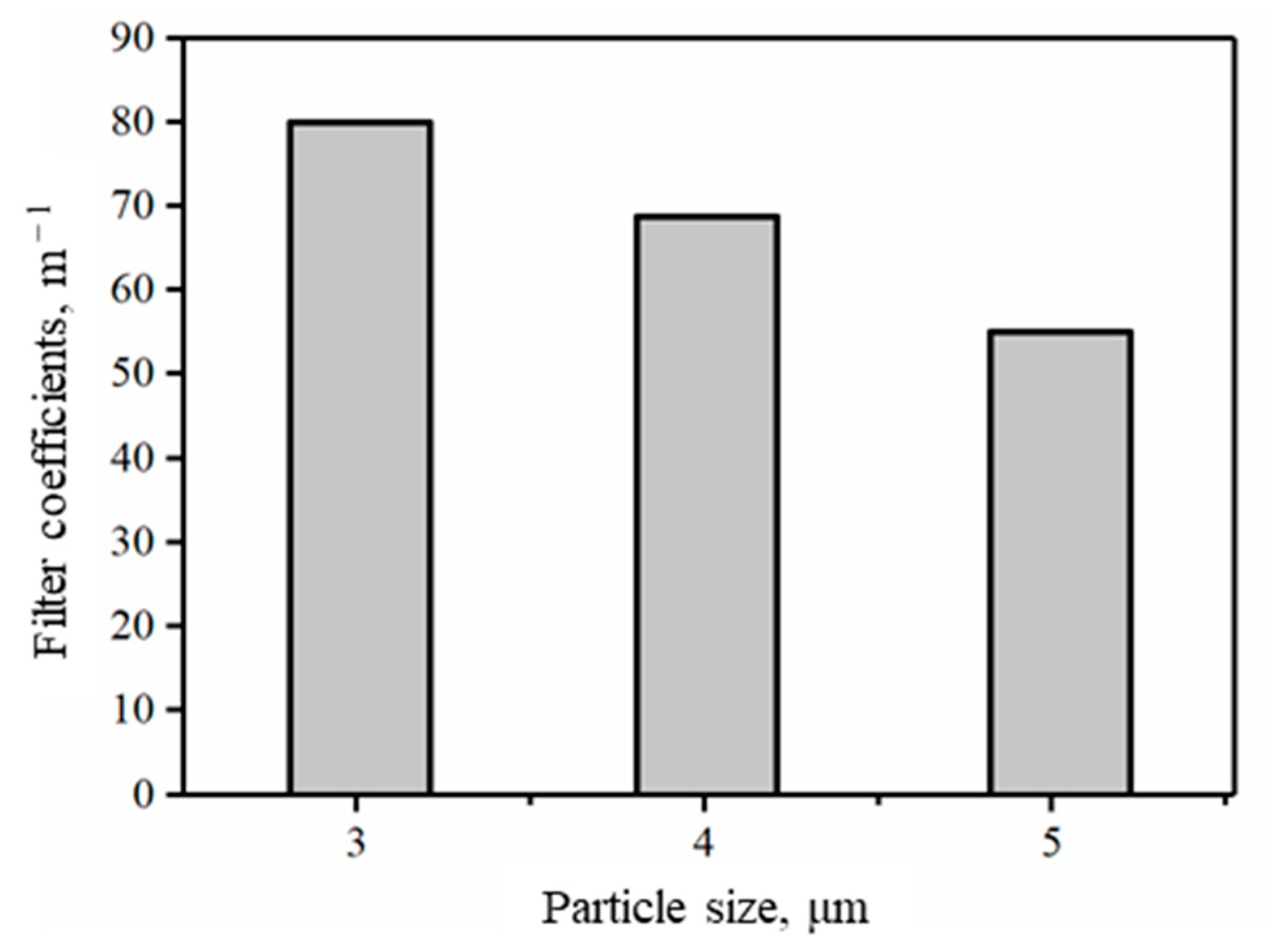
4.3. Analysis of Influencing Factors of Filtration Coefficient

As can be seen from Figure 14, the filtration coefficient decreases gradually with the increase in throat size. This is because when the throat size increases, the particle volume becomes smaller compared to the throat space; thus, there is a smaller chance of contact with the wall of the porous media, resulting in a lower probability of particle deposition. The increase in throat size leads to the decrease in the filtration coefficient. This indicates that large throats are less likely to cause particle retention and that large throats can better maintain formation permeability and have a certain effect on the barrier of foreign permeability.
As can be seen from Figure 15, the filtration coefficient will decrease slightly with the increase in flow rate. This is because when the flow rate increases, the flow rate of the particles also increases because it is assumed that the particle has the same velocity with the flow rate. Therefore, the flow distance of the particles per unit time increases, and the probability of staying decreases. The filtration coefficient decreases with the increase in flow rate.
As can be seen from Figure 16, the filtration coefficient increases with the increase in particle size. This is because with the increase in particle size, the particle has more space to contact the throat, which increases the possibility of deposition, thus leading to an increase in the probability of particle deposition. The increase in throat size leads to an increase in the degree of the filtration coefficient, indicating that large particles are more likely to cause a retention of particles. Therefore, for the formation, the intrusion of large particles into the layer should be avoided as much as possible.

5. Conclusions

We have proposed a model here to show conductivity decline due to fine-grained particle migration and proppant embedment in weakly cemented sandstone and coal-bed methane reservoirs. A network model was established to solve the filtration coefficient of porous media particles. The model can be used to study the relationship between the filtration coefficient of porous media particles and rock particle diameter, porous media particle size, and formation fluid flow rate. In this new model, we considered the influence of rock compressibility, proppant embedment and fine-grained particle attachment. The partial differential equation system was solved numerically. An experiment with all influencing factors was conducted here, which illustrate the effect of fine-grained particle migration and embedment effect on conductivity.
The results illustrate that both embedment and fine-grained particle migration have a great negative effect on conductivity of fractures in weakly cemented sandstone and coal-bed methane reservoirs. The formulation we proposed matches the experimental data smoothly and can be widely used in the prediction of conductivity decline in weakly cemented sandstone and coal-bed methane reservoirs. The simulation results show that the filtration coefficient increases with an increase in particle size, an increase in porous medium throat size, and a decrease in fluid velocity. At the same time, it was found that the large larynx did not easily cause particle retention. Large size particles tend to cause particle retention.

Author Contributions

Conceptualization, W.Z.; Data curation, X.G. and Z.W. (Zhiwen Wang); Funding acquisition, W.Z.; Investigation, X.G. and Z.W. (Zhiwen Wang); Project administration, W.Z.; Supervision, W.Z. and Z.W. (Zizhen Wang); Writing—review & editing, Q.Z. and Z.W. (Zizhen Wang). All authors have read and agreed to the published version of the manuscript.

Funding

This research was funded by [the National Natural Science Foundation of China] grant number [51374229], and [the Natural Science Foundation of Shandong Province of China] grant number [ZR2019MEE101].

Institutional Review Board Statement

Not applicable.

Informed Consent Statement

Not applicable.

Data Availability Statement

The data in the tables used to support the findings of this study are included within the article. The data in the figures used to support the findings of this study are available from the corresponding author ([email protected] and [email protected]) upon request.

Acknowledgments

The authors acknowledge the experimental supports from Maoyong Fu and Shouqiang Zhao.

Conflicts of Interest

The authors declare no conflict of interest.

References

  1. Lehman, L.V.; Blauch, M.E.; Robert, L.M. Desorption enhancement in fracture-stimulated coalbed methane wells—SPE 51063. In Proceedings of the SPE Eastern Regional Meeting, Pittsburgh, PA, USA, 9–11 November 1998. [Google Scholar]
  2. Zou, Y.S.; Zhang, S.C.; Zhang, J. Experimental method to simulate coal fines migration and coal fines aggregation prevention in the hydraulic fracture. Transp. Porous Media 2014, 101, 17–34. [Google Scholar] [CrossRef]
  3. Alramahi, B.; Sundberg, M.I. Proppant embedment and conductivity of hydraulic fractures in shales. In Proceedings of the 46th U.S. Rock Mechanics/Geomechanics Symposium, Chicago, IL, USA, 24–27 June 2012. [Google Scholar]
  4. Bedrikovetsky, P.; Vaz, A.; Machado, F.; Zeinijahromi, A.; Borazjani, S. Skin due to fines mobilization, migration, and straining during steady-state oil production. Pet. Sci. Technol. 2012, 30, 1539–1547. [Google Scholar] [CrossRef]
  5. Guo, Z.; Hussain, F.; Cinar, Y. Physical and analytical modelling of permeability damage in bituminous coal caused by fines migration during water production. J. Nat. Gas Sci. Eng. 2016, 35, 331–346. [Google Scholar] [CrossRef]
  6. Bai, T.; Chen, Z.; Aminossadati, S.M.; Li, L.; Liu, J.; Lu, H. Dimensional analysis and prediction of coal fines generation under two-phase flow conditions. Fuel 2017, 194, 460–479. [Google Scholar] [CrossRef]
  7. Coronado, M.; Díaz-Viera, M.A. Modeling fines migration and permeability loss caused by low salinity in porous media. J. Pet. Sci. Eng. 2017, 150, 355–365. [Google Scholar] [CrossRef]
  8. Sen, T.K.; Khilar, K.C. Review on subsurface colloids and colloid-associated contaminant transport in saturated porous media. Adv. Colloid Interface Sci. 2006, 119, 71–96. [Google Scholar]
  9. Xu, X.F.; Hao, J.; Yu, L.; Deng, Y.R. Fuzzy optimal allocation model for task-resource assignment problem in collaborative logistics network. IEEE Trans. Fuzzy Syst. 2019, 27, 1112–1125. [Google Scholar] [CrossRef]
  10. Lagasca, J.R.P.; Kovscek, A.R. Fines migration and compaction in diatomaceous rocks. J. Pet. Sci. Eng. 2014, 122, 108–118. [Google Scholar] [CrossRef]
  11. Zeinijahromi, A.; Farajzadeh, R.; Bruining, J.; Bedrikovetsky, P. Effect of fines migration on oil–water relative permeability during two-phase flow in porous media. Fuel 2016, 176, 222–236. [Google Scholar] [CrossRef]
  12. Xu, X.F.; Hao, J.; Zheng, Y. Multi-objective artificial bee colony algorithm for multi-stage resource leveling problem in sharing logistics network. Comput. Ind. Eng. 2020, 142, 106338. [Google Scholar] [CrossRef]
  13. Herzig, J.P.; Leclerc, D.M.; Le Goff, P. Flow of Suspensions through Porous Media—Application to Deep Filtration. Ind. Eng. Chem. 1970, 62, 8–35. [Google Scholar] [CrossRef]
  14. Bedrikovetsky, P.; Siqueira, F.D.; Furtado, C.A.; Souza, A.L.S. Modified particle detachment model for colloidal transport in porous media. Transp. Porous Media 2011, 86, 353–383. [Google Scholar] [CrossRef]
  15. Sharma, M.M.; Yortsos, J.C. Fines migration in porous media. Aiche J. 1987, 33, 1654–1662. [Google Scholar] [CrossRef]
  16. Zhang, J.; Kamenov, A.; Zhu, D.; Hill, A.D. Development of new testing procedures to measure propped fracture conductivity considering water damage in clay-rich shale reservoirs: An example of the Barnett Shale. J. Pet. Sci. Eng. 2015, 135, 352–359. [Google Scholar] [CrossRef] [Green Version]
  17. Tan, Y.; Pan, Z.; Liu, J.; Wu, Y.; Haque, A.; Connell, L.D. Experimental study of permeability and its anisotropy for shale fracture supported with proppant. J. Nat. Gas Sci. Eng. 2017, 44, 250–264. [Google Scholar] [CrossRef]
  18. Zheng, X.; Chen, M.; Hou, B.; Ye, Z.; Wang, W.; Yin, C.; Chen, X. Effect of proppant distribution pattern on fracture conductivity and permeability in channel fracturing. J. Pet. Sci. Eng. 2017, 149, 98–106. [Google Scholar] [CrossRef]
  19. Mahmood, S.; Ehsan, K.; Ahmad, F.; Bahram, D. A mechanistic study of smart water injection in the presence of nanoparticles for sand production control in unconsolidated sandstone reservoirs. J. Mol. Liq. 2020, 319, 114210. [Google Scholar]
  20. Wang, J.; Huang, Y.; Zhou, F.; Liang, X. The influence of proppant breakage, embedding, and particle migration on fracture conductivity. J. Pet. Sci. Eng. 2020, 193, 107385. [Google Scholar] [CrossRef]
  21. Chen, D.; Ye, Z.; Pan, Z.; Zhou, Y.; Zhang, J. A permeability model for the hydraulic fracture filled with proppant packs under combined effect of compaction and embedment. J. Pet. Sci. Eng. 2017, 149, 428–435. [Google Scholar] [CrossRef] [Green Version]
  22. Mojarad, R.S.; Settari, A.T. Coupled numerical simulation of reservoir flow with formation plugging. J. Can. Pet. Technol. 2007, 46, 54–59. [Google Scholar] [CrossRef]
  23. Wang, Z.; Zhou, W.; Shu, T.; Xue, Q.; Zhang, R.; Wiercigroch, M. Modelling of low-frequency acoustic wave propagation in dilute gas-bubbly liquids. Int. J. Mech. Sci. 2022, 216, 106979. [Google Scholar] [CrossRef]
  24. Huang, F.; Kang, Y.; You, Z.; You, L.; Xu, C. Critical Conditions for Massive Fines Detachment Induced by Single-Phase Flow in Coalbed Methane Reservoirs: Modeling and Experiments. Energy Fuels 2017, 31, 6782–6793. [Google Scholar] [CrossRef]
  25. Pu, C.S. Micro-Kinetics of Particle Deposition, Dispersion and Migration on the Surface of the Liquid-Solid System; Petroleum Industry Press: Beijing, China, 2008; pp. 52–79. [Google Scholar]
  26. Zheng, L.S.; Pu, C.S.; Liu, J.; Xu, J.X.; Tian, C.D. Analysis of particle migration in porous media under elastic wave. J. Chongqing Univ. 2016, 39, 101–108. [Google Scholar]
  27. Li, H.P.; Chen, X.H.; Li, L.C.; Liu, X.J. Particle migration character of unconsolidated reservoir and its influence on oil performance. Fault-Block Oil Gas Field 1996, 3, 31–34. [Google Scholar]
  28. Ju, B.; Ma, M.; Qiu, X. The mathematical simulation method of migration of fines and clay swell in elastic porous medium. J. Hydrodyn. 2003, 18, 8–15. [Google Scholar]
  29. Yuan, H.; Shapiro, A.A. Induced migration of fines during waterflooding in communicating layer-cake reservoirs. J. Pet. Sci. Eng. 2011, 78, 618–626. [Google Scholar] [CrossRef] [Green Version]
  30. Zhou, S.; Zhang, X.; Wu, D.; Di, H. Mathematical Modeling of Slurry Infiltration and Particle Dispersion in Saturated Sand. Transp. Porous Media 2018, 124, 91–116. [Google Scholar] [CrossRef]
  31. Ju, Y.S.; Ma, X.F.; Wang, L.; Lin, X. Experimental evaluation of conductivity of fracturing in medium and high-rank coalbed. J. China Coal Soc. 2011, 36, 473–476. [Google Scholar]
  32. Hazlett, R.D. Statistical characterization and stochastic modeling of pore networks in relation to fluid flow. Math. Geol. 1997, 29, 801–822. [Google Scholar] [CrossRef]
  33. Øren, P.-E.; Bakke, S. Reconstruction of Berea sandstone and pore-scale modeling of wettability effects. J. Pet. Sci. Eng. 2003, 39, 177–199. [Google Scholar] [CrossRef]
  34. Yuan, H.; You, Z.; Shapiro, A.; Bedrikovetsky, P. Improved population balance model for straining-dominant deep bed filtration using network calculations. Chem. Eng. J. 2013, 226, 227–237. [Google Scholar] [CrossRef] [Green Version]
  35. Song, W.; Kovscek, A.R. Direct visualization of pore-scale fines migration and formation damage during low-salinity waterflooding. J. Nat. Gas Sci. Eng. 2016, 34, 1276–1283. [Google Scholar] [CrossRef]
Figure 1. Schematic of fine-grained particle migration in the fractured layer and proppant filled fracture.
Energies 15 02359 g001
Figure 2. Schematic of proppant embedment in a fracture under stress: (a) the proppant before embedment; (b) the proppant embedment with increased stress (after [21]).
Energies 15 02359 g002
Figure 3. Schematic of conductivity measurement setup and rock plate size.
Energies 15 02359 g003
Figure 4. Effect of cement content on embedment depth.
Energies 15 02359 g004
Figure 5. Effect of cement content on fracture conductivity.
Energies 15 02359 g005
Figure 6. Effect of fine-grained particle concentration on conductivity.
Energies 15 02359 g006
Figure 7. Effect of flow rate on conductivity.
Energies 15 02359 g007
Figure 8. Coal fines distribution in conductivity cell after experiment, and simulation results. (a) Experiment result from Zou et al. [2]; (b) fine-grained particle migration simulation after 20 min; (c) fine-grained particle migration simulation after 1 h; (d) fine-grained particle migration simulation after 2 h.
Energies 15 02359 g008
Figure 9. The influence of coal fines concentration on the conductivity variation trends with pressure.
Energies 15 02359 g009
Figure 10. Force analysis of particles in the horizontal throat.
Energies 15 02359 g010
Figure 11. Diagrammatic of throat selection for particle migration.
Energies 15 02359 g011
Figure 12. Diagrammatic of network model.
Energies 15 02359 g012
Figure 13. Algorithm diagram of how to solve the network model.
Energies 15 02359 g013
Figure 14. Influence of channel radius on the filtration coefficient.
Energies 15 02359 g014
Figure 15. Influence of flow velocity on the filtration coefficient.
Energies 15 02359 g015
Figure 16. Influence of particle size on the filtration coefficient.
Energies 15 02359 g016
Table 1. Parameters used in the experiment.
ParameterValue
Proppant size, d20–40 mesh
Porosity, ϕ22.5%
Initial permeability, k700 mD
Suspension viscosity, μs1 mPa·s
Injection rate, Q10 mL/min
Pressure at outlet, P1 atm
Filtration coefficient, λ11.8 L−1
Proppant pack compressibility, α−0.022
Initial effective stress, σe00 MPa
Damage coefficient212 (g/L)−1
Table 2. Parameters involved in the experiment by Zou et al. (2014).
ParameterValue
Proppant size, d200–425 µm
Porosity, ϕ20.3%
Initial permeability, k400 mD
Suspension viscosity, μs1 mPa·s
Injection rate, Q200 mL/min
Pressure at outlet, P1 atm
Filtration coefficient, λ10 L−1
proppant pack compressibility, α−0.028
Initial effective stress, σe00 MPa
Damage coefficient182 (g/L)−1
Table 3. Advantages and disadvantages of the models.
Micro ModelAdvantagesDisadvantages
Capillary modelThe capillary model is simple and easy to calculate.The model is too simple to reflect the real core, and the accuracy is not enough.
Network modelThe model has high accuracy.The model is relatively complex, and the calculation is complicated.
Element modelThe model is simple.The calculation is relatively complex and cannot simulate complex structure.
Numerical modelAccurate calculation and comprehensive consideration.Computations take a long time and require high-performance computers.
Table 4. Network model parameter selection table.
Name of ParameterParameter Choice
Pore diameter30 μm
Shouted the diameter30 μm
Shouted the length200 μm
Coordination number4
Void ratio28.2%
Number of particles100
Publisher’s Note: MDPI stays neutral with regard to jurisdictional claims in published maps and institutional affiliations.

