
Control of the Solar Radiation Reception Rate (SRRR) Using a Novel Poly-Tilted Segmented Panel (PTSP) in the Region of Makkah, Saudi Arabia


 , ,
, , 
Abstract
1. Introduction
- For solar thermal panels, the SRRR control avoids additional charges and fees related to additional equipment and their maintenance.
- The proposed PTSP design, in itself, presents an efficient sustainable design (environmentally friendly (not powered electrical energy), simple and cheap) alternative to expensive sun tracking systems which are powered by electrical energy deriving from fossil energy.
2. Problem Statement
3. Mathematical Modeling
4. Results and Discussion
5. Conclusions
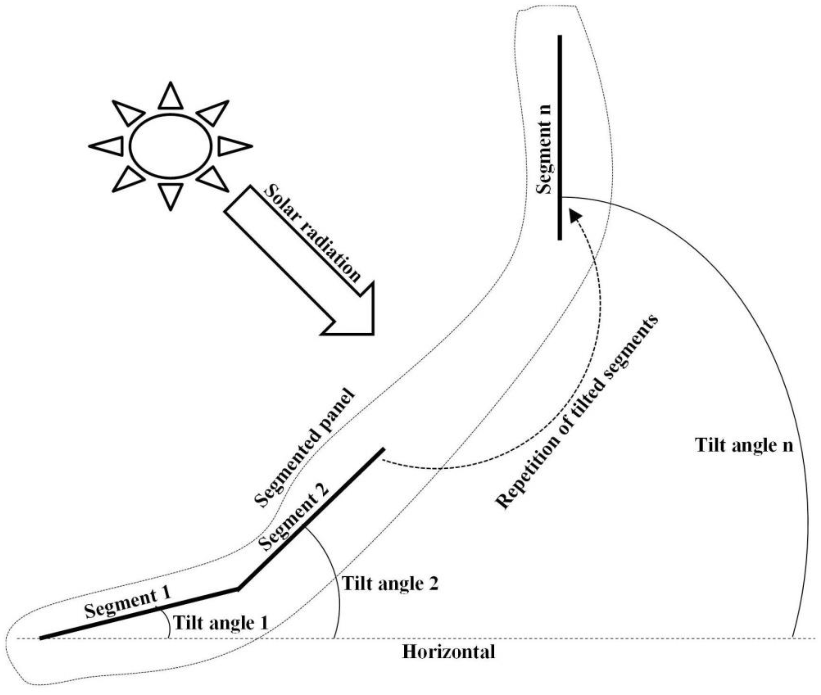
- A PTSP is proposed as a novel technological solution permitting control of the daily received amount of solar radiation directly related to the SRRR. It is necessary to carry out SRRR control under extremely sunny conditions, such as the case of the city of Makkah (21.3891° N, 39.8579° E), Saudi Arabia, in order to ensure proper functioning of some solar powered technologies (such as solar thermal and photovoltaic). Sustainability of cities and villages located in extremely sunny regions is, then, promoted.
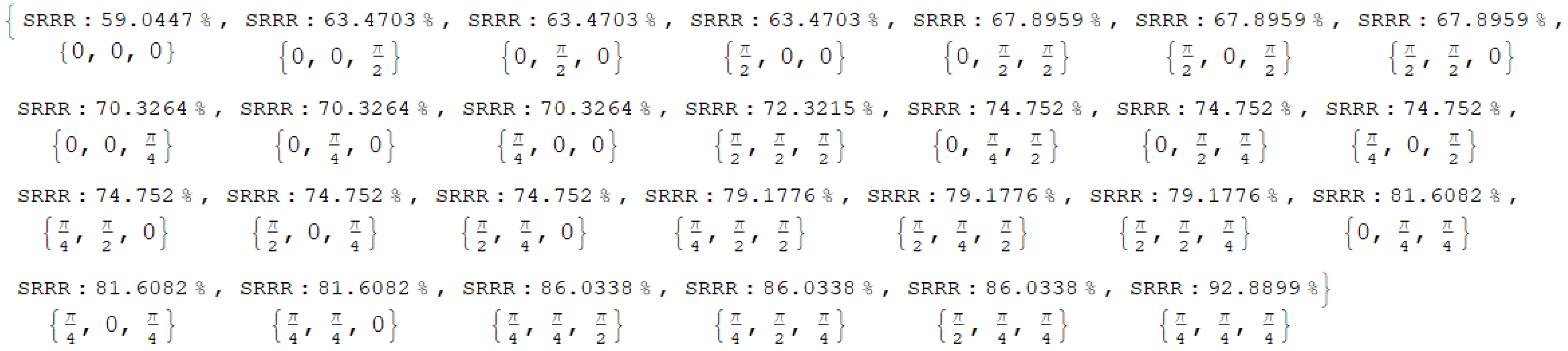
- At the equinox:
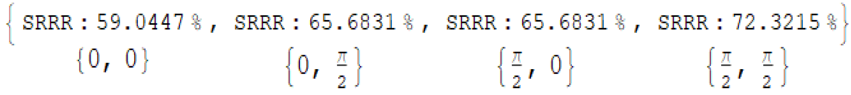
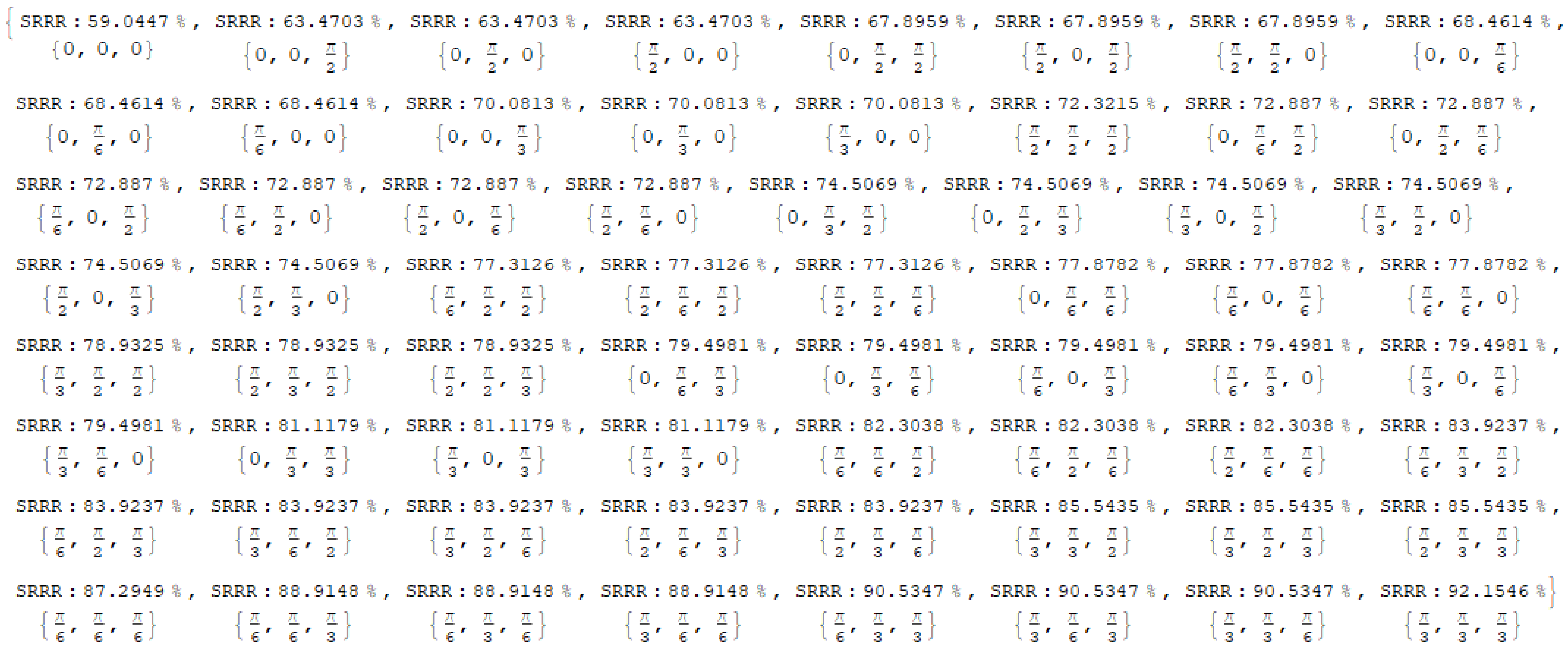
- For to segments and two tilt angle divisions (): the SRRR varies from 59.04% to 72.32% for segment/tilt combinations of and , respectively.
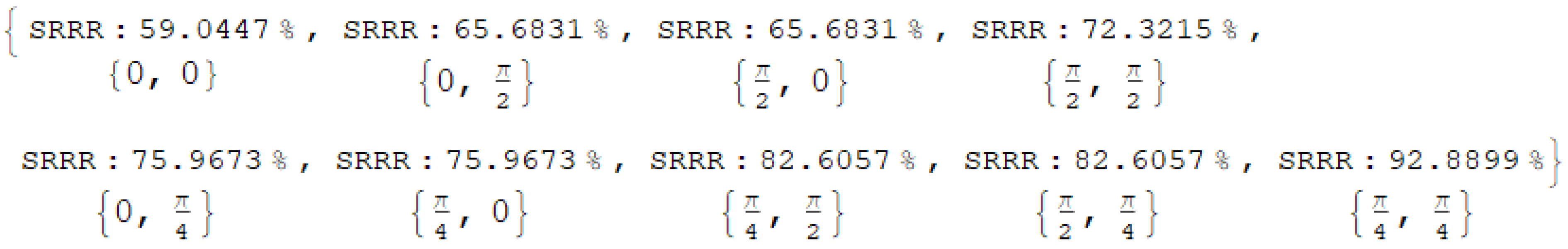
- For two segments and three tilt angle divisions (): the SRRR varies from 59.04% to 92.89% for segment/tilt combinations of and , respectively.
- For three segments and three tilt angle divisions (): the SRRR varies from 59.04% to 92.89% for segment/tilt combinations of and , respectively.
- For three segments and four tilt angle divisions (): the SRRR varies from 59.04% to 92.15% for a segment/tilt combinations of and , respectively.
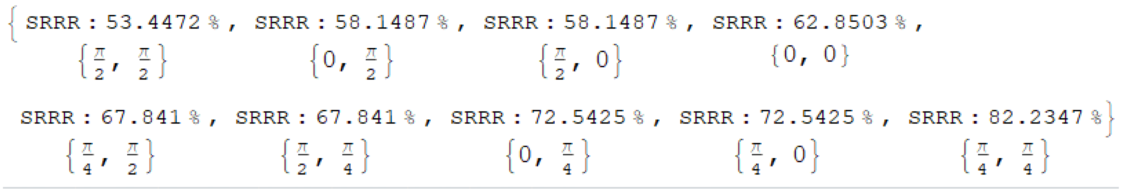
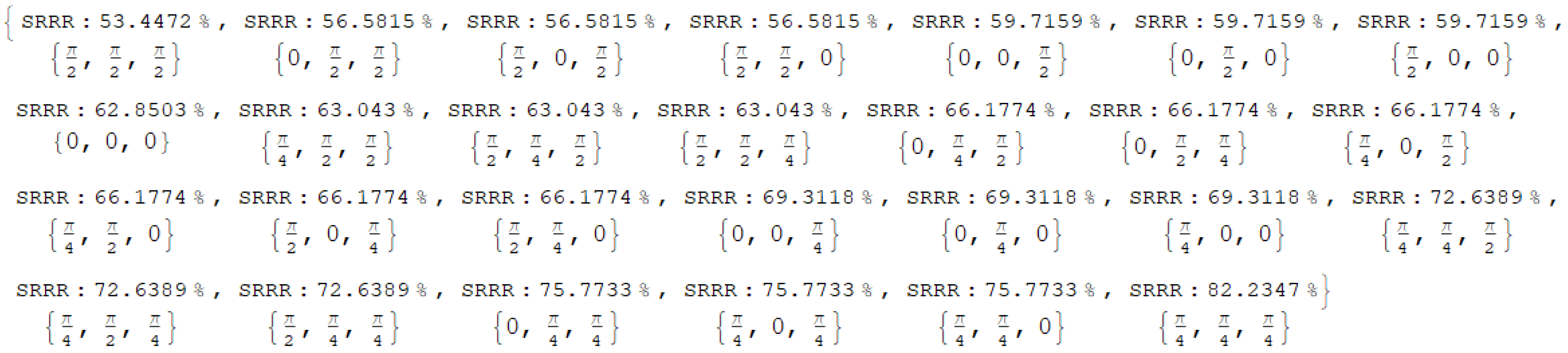
- At the summer solstice:
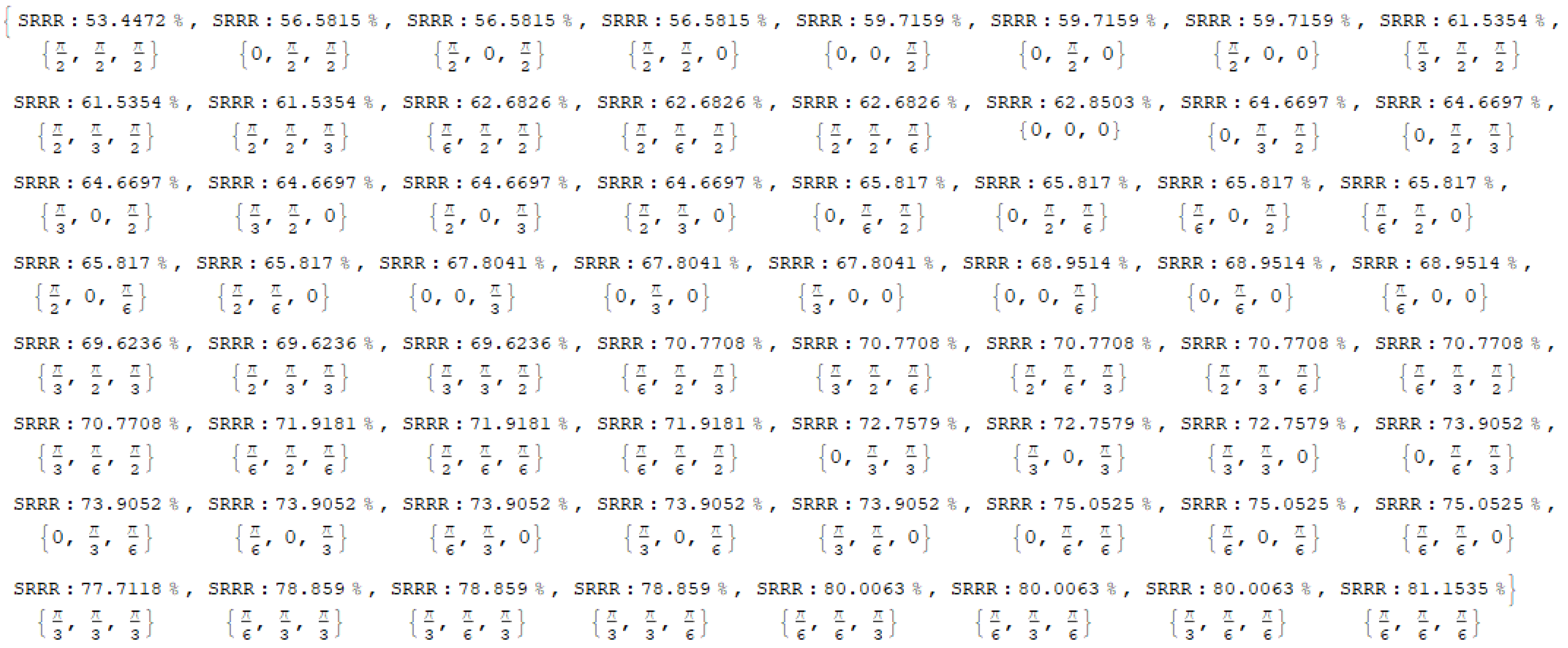
- For two segments and two tilt angle divisions (): the SRRR varies from 53.45% to 62.85% for segment/tilt combinations of and , respectively.
- For two segments and three tilt angle divisions (): the solar SRRR varies from 53.45% to 82.23% for segment/tilt combinations of and , respectively.
- For three segments and three tilt angle divisions (): the SRRR varies from 53.45% to 82.23% for segment/tilt combinations of and , respectively.
- For three segments and four tilt angle divisions (): the SRRR varies from 53.45% to 81.15% for segment/tilt combinations of and , respectively.
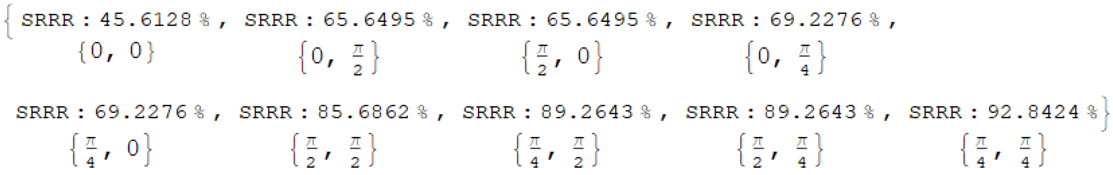
- At the winter solstice:
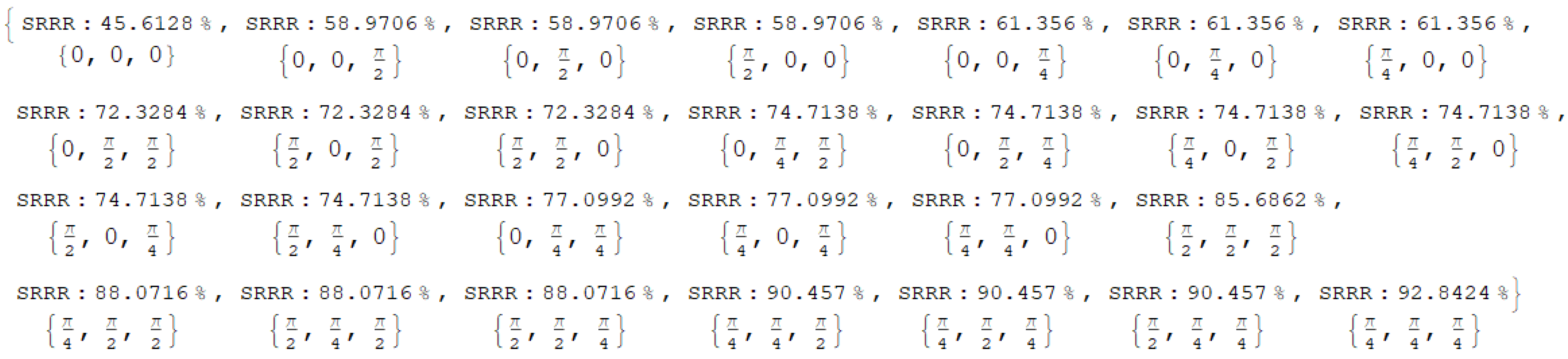
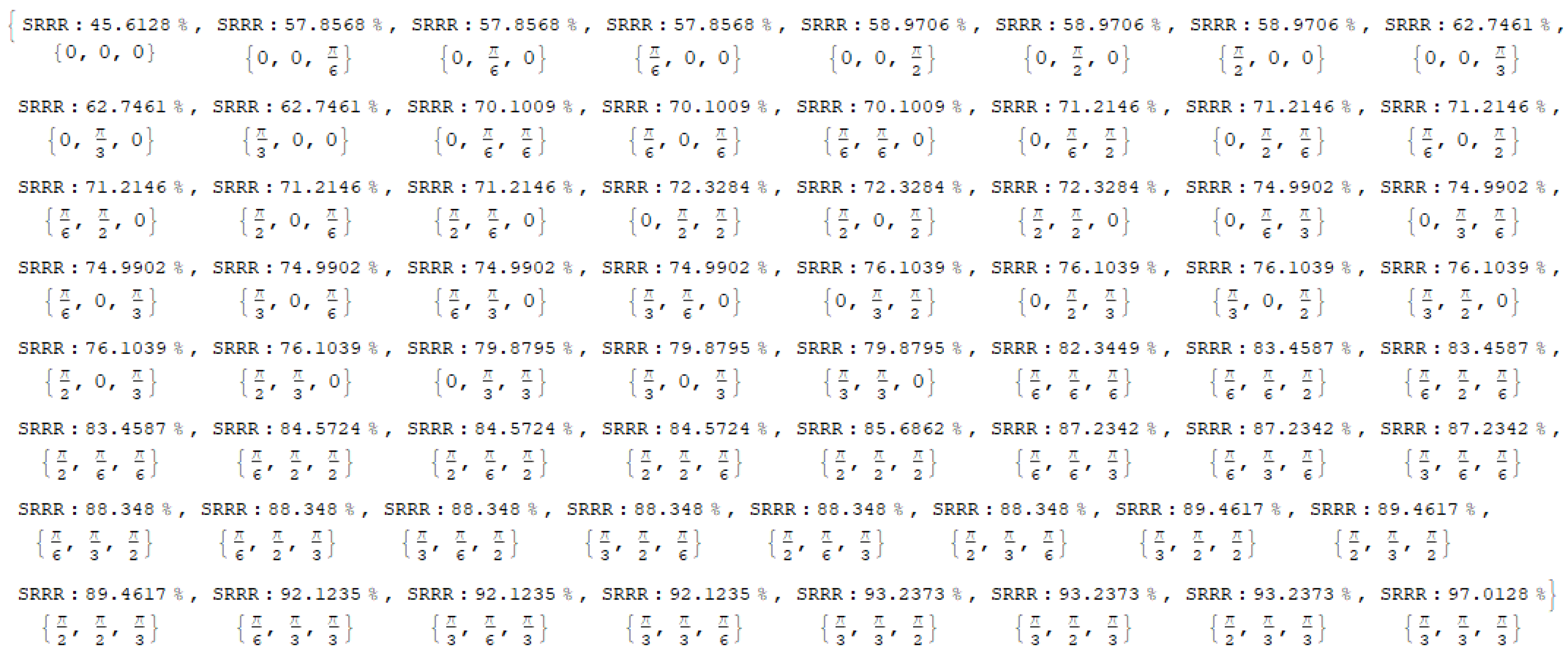
- For two segments and two tilt angle divisions (): the SRRR varies from 45.61% to 85.69% for segment/tilt combinations of and , respectively.
- For two segments and three tilt angle divisions (): the SRRR varies from 45.61% to 92.84% for segment/tilt combinations of and , respectively.
- For three segments and three tilt angle divisions (): the SRRR varies from 45.61% to 92.84% for segment/tilt combinations of and , respectively.
- For three segments and four tilt angle divisions (): the SRRR varies from 45.61% to 97.01% for segment/tilt combinations of and , respectively.
- When the tilt angle division increases from two to three divisions for three segments, the maximum SRRR is slightly reduced by 0.74% at the equinox and by 1.08% at the summer solstice, while it increases by 4.17% at the winter solstice. When the number of segments increases from two to three segments for two tilt angle divisions, the SRRR range is not affected but it is more quantified, which gives more possibilities to the SRRR control management since further SRRR levels within the SRRR range are specified. This will permit accurate adjustment of the appropriate SRRR.
Supplementary Materials
Author Contributions
Funding
Institutional Review Board Statement
Informed Consent Statement
Data Availability Statement
Acknowledgments
Conflicts of Interest
Nomenclature
| d | Day number |
| E | Equation of time |
| I | Incident solar radiation (W/m2) |
| L | Longitude |
| m | Number of panel segments |
| n | Number of tilt angle divisions |
| PTSP | Poly-tilted segmented panel |
| SRRR | Solar radiation reception rate (%) |
| T | Time (hour) |
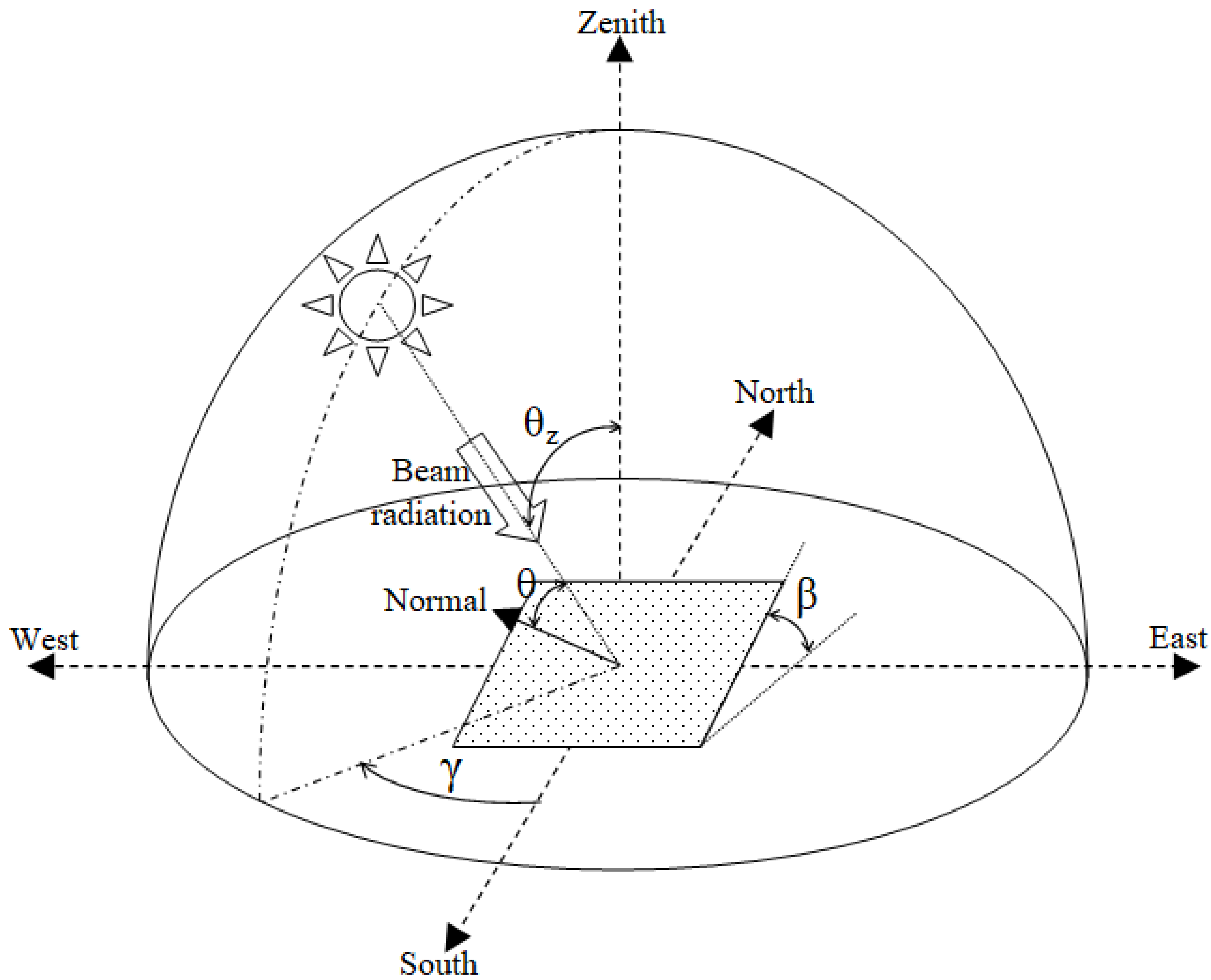
| β | Tilt angle combination (rd°) |
| γ | Azimuth angle (rd°) |
| δ | Declination angle (rd°) |
| θ | Incidence angle |
| φ | Latitude angle (rd°) |
| ω | Hour angle (rd°) |
| g | Global |
| l | Local time |
| lo | Local meridian |
| r | Sun rise |
| s | Sun set |
| t | Tilted panel |
| sm | Standard meridian |
| so | Solar time |
| z | Zenith |
References
- Veeraboina, P.; Guduri, G.Y. Analysis of yearly solar radiation by using correlations based on ambient temperature: India. Sustain. Cities Soc. 2014, 11, 16–21. [Google Scholar] [CrossRef]
- Maatallah, T.; El Ouderni, A.R.; El Alimi, S.; Nasrallah, S.B. Experimental study of solar flux energy basing on measured sun covering-rate in the gulf of Tunis, Tunisia. Sustain. Cities Soc. 2012, 5, 63–69. [Google Scholar] [CrossRef]
- Liu, Y.; Zhang, M.; Li, Q.; Zhang, T.; Yang, L.; Liu, J. Investigation on the distribution patterns and predictive model of solar radiation in urban street canyons with panorama images. Sustain. Cities Soc. 2021, 75, 103275. [Google Scholar] [CrossRef]
- Veeraboina, P.; Yesuratnam, G.; Sundar, L.S. Estimation of Annual Solar Radiation from measured temperatures by using Temperature-based (TB) approach in different cities in India. Sustain. Cities Soc. 2011, 1, 187–194. [Google Scholar] [CrossRef]
- Iqbal, M. An Introduction to Solar Radiation; Academic Press: Cambridge, MA, USA, 1983; ISBN 978-0-12-373750-2. [Google Scholar] [CrossRef]
- Palz, W. Solar Radiation Data: Proceedings of the EC Contractors’ Meeting Held in Brussels, 18–19 October 1982; Springer: Dordrecht, The Netherlands, 1983; ISBN 978-94-009-7112-7. [Google Scholar] [CrossRef]
- Ulgen, K.; Hepbasli, A. Solar Radiation Models. Part 1: A Review. Energy Sources 2004, 26, 507–520. [Google Scholar] [CrossRef]
- Badescu, V. Modeling Solar Radiation at the Earth’s Surface: Recent Advances; Springer: Berlin/Heidelberg, Germany, 2008; ISBN 978-3-540-77455-6. [Google Scholar] [CrossRef]
- Palz, W.; Greif, J. Commission of the European Communities (CEC), European Solar Radiation Atlas: Solar Radiation on Horizontal and Inclined Surfaces; Springer: Berlin/Heidelberg, Germany, 1996; ISBN 978-3-642-80237-9. [Google Scholar] [CrossRef]
- Jin, Z.; Yezheng, W.; Gang, Y. Generation of typical solar radiation year for China. Renew. Energy 2006, 31, 1972–1985. [Google Scholar] [CrossRef]
- McAneney, K.J.; Noble, P.F. Estimating solar radiation on sloping surfaces. N. Z. J. Exp. Agric. 1976, 4, 195–202. [Google Scholar] [CrossRef][Green Version]
- Alvi, S.H.; Abdalla, Y.A.G. Estimation of solar radiation for Oman. Int. J. Ambient. Energy 1992, 13, 11–18. [Google Scholar] [CrossRef]
- Chandra, M.; Saxena, B.K.; Varshneyaxena, N.C. Solar Radiation and Illumination on Inclined Planes for Clear Atmospheric Conditions. J. Opt. 1982, 11, 47–54. [Google Scholar] [CrossRef]
- Forero, N.L.; Caicedo, L.M.; Gordillo, G. Correlation of global solar radiation values estimated and measured on an inclined surface for clear days in Bogotá. Renew. Energy 2007, 32, 2590–2602. [Google Scholar] [CrossRef]
- Pandey, C.K.; Katiyar, A.K. Hourly solar radiation on inclined surfaces. Sustain. Energy Technol. Assess. 2014, 6, 86–92. [Google Scholar] [CrossRef]
- Elnesr, M.K.; Khalil, A.M. Total solar radiation on vertical and inclined surfaces during cloudless days in the UAR. Pure Appl. Geophys. 1965, 60, 217–228. [Google Scholar] [CrossRef]
- Shukla, K.N.; Rangnekar, S.; Sudhakar, K. Mathematical modelling of solar radiation incident on tilted surface for photovoltaic application at Bhopal, M.P., India. Int. J. Ambient. Energy 2016, 37, 579–588. [Google Scholar] [CrossRef]
- Das, M.; Akpinar, E.K. Investigation of the effects of solar tracking system on performance of the solar air dryer. Renew. Energy 2021, 167, 907–916. [Google Scholar] [CrossRef]
- Fazlizan, A.; Abdulmula, A.; Amran, A.N.; Lim, C.H.; Sopian, K. Performance evaluation of maximum light detection solar tracking system in the tropics. J. Mech. Sci. Technol. 2019, 33, 1391–1397. [Google Scholar] [CrossRef]
- ElGamal, R.; Kishk, S.; Al-Rejaie, S.; ElMasry, G. Incorporation of a solar tracking system for enhancing the performance of solar air heaters in drying apple slices. Renew. Energy 2021, 167, 676–684. [Google Scholar] [CrossRef]
- Jamroen, C.; Fongkerd, C.; Krongpha, W.; Komkum, P.; Pirayawaraporn, A.; Chindakham, N. A novel UV sensor-based dual-axis solar tracking system: Implementation and performance analysis. Appl. Energy 2021, 299, 117295. [Google Scholar] [CrossRef]
- Batayneh, W.; Bataineh, A.; Soliman, I. Investigation of solar tracking performance using isotropic and anisotropic models. Adv. Build. Energy Res. 2021, 15, 390–408. [Google Scholar] [CrossRef]
- Aste, N.; del Pero, C.; Adhikari, R.S.; Marenzi, G. Effectiveness and weaknesses of supporting policies for solar thermal systems—A case-study. Sustain. Cities Soc. 2015, 14, 146–153. [Google Scholar] [CrossRef]
- Lin, W.-M.; Chang, K.-C.; Chung, K.-M. Economic aspects for solar thermal application in Taiwan. Sustain. Cities Soc. 2016, 26, 354–363. [Google Scholar] [CrossRef]
- Asrami, R.F.; Sohani, A.; Saedpanah, E.; Sayyaadi, H. Towards achieving the best solution to utilize photovoltaic solar panels for residential buildings in urban areas. Sustain. Cities Soc. 2021, 71, 102968. [Google Scholar] [CrossRef]
- Huang, J.; Wang, Q.; Chen, X.; Xu, S.; Yang, H. Experimental investigation and annual overall performance comparison of different photovoltaic vacuum glazings. Sustain. Cities Soc. 2021, 75, 103282. [Google Scholar] [CrossRef]
- do Nascimento, L.R.; de Souza Viana, T.; Campos, R.A.; Rüther, R. Extreme solar overirradiance events: Occurrence and impacts on utilityscale photovoltaic power plants in Brazil. Sol. Energy 2019, 186, 370–381. [Google Scholar] [CrossRef]
- Rüther, R.; Nascimento, L.R.; Campos, R.A. Performance assessment issues in utility-scale photovoltaics in warm and sunny climates. Renew. Energy Environ. Sustain. 2017, 2, 35. [Google Scholar] [CrossRef]
- Chen, S.; Li, P.; Brady, D.; Lehman, B. The impact of irradiance time behaviors on inverter sizing and design. In Proceedings of the 2010 IEEE 12th Workshop on Control and Modeling for Power Electronics (COMPEL), Boulder, CO, USA, 28–30 June 2010; pp. 1–5. [Google Scholar] [CrossRef]
- Burger, B.; Rüther, R. Inverter sizing of grid-connected photovoltaic systems in the light of local solar resource distribution characteristics and temperature. Solar Energy 2006, 80, 32–45. [Google Scholar] [CrossRef]
- Kim, J.; Rabelo, M.; Padi, S.P.; Yousuf, H.; Cho, E.-C.; Yi, J. A Review of the Degradation of Photovoltaic Modules for Life Expectancy. Energies 2021, 14, 4278. [Google Scholar] [CrossRef]
- Rosa-Clot, M.; Tina, G.M. Chapter 2—Photovoltaic Electricity, Submerged and Floating Photovoltaic Systems: Modelling, Design and Case Studies; Academic Press: Cambridge, MA, USA, 2018; pp. 13–32. [Google Scholar] [CrossRef]
- Dincer, I. Comprehensive Energy Systems; Elsevier: Amsterdam, The Netherlands, 2018; ISBN 978-0-12-814925-6. [Google Scholar]
- Kalogirou, S.A. McEvoy’s Handbook of Photovoltaics: Fundamentals and Applications, 3rd ed.; Academic Press: Cambridge, MA, USA, 2017; ISBN 978-0-12-809921-6. [Google Scholar] [CrossRef]
- Sayigh, A. Comprehensive Renewable Energy; Elsevier: Amsterdam, The Netherlands, 2012; ISBN 978-0-08-087873-7. [Google Scholar]
- Almarshoud, A.F. Performance of solar resources in Saudi Arabia. Renew. Sustain. Energy Rev. 2016, 66, 694–701. [Google Scholar] [CrossRef]
- Kalogirou, S.A. Chapter 2—Environmental Characteristics, Solar Energy Engineering (Second Edition): Processes and Systems; Academic Press: Cambridge, MA, USA, 2014; pp. 51–123. [Google Scholar] [CrossRef]
- Sarbu, I.; Sebarchievici, C. Chapter 2—Solar Radiation, Solar Heating and Cooling Systems: Fundamentals, Experiments and Applications; Academic Press: Cambridge, MA, USA, 2017; pp. 13–28. [Google Scholar] [CrossRef]
- Benghanem, M. Optimization of tilt angle for solar panel: Case study for Madinah, Saudi Arabia. Appl. Energy 2011, 88, 1427–1433. [Google Scholar] [CrossRef]
- Wolfram Mathematica. Available online: https://reference.wolfram.com/language/ref/Tuples.html (accessed on 20 December 2021).


Publisher’s Note: MDPI stays neutral with regard to jurisdictional claims in published maps and institutional affiliations. |
© 2022 by the authors. Licensee MDPI, Basel, Switzerland. This article is an open access article distributed under the terms and conditions of the Creative Commons Attribution (CC BY) license (https://creativecommons.org/licenses/by/4.0/).
Share and Cite
Alqurashi, F.; Nciri, R.; Alghamdi, A.; Ali, C.; Nasri, F. Control of the Solar Radiation Reception Rate (SRRR) Using a Novel Poly-Tilted Segmented Panel (PTSP) in the Region of Makkah, Saudi Arabia. Energies 2022, 15, 2357. https://doi.org/10.3390/en15072357
Alqurashi F, Nciri R, Alghamdi A, Ali C, Nasri F. Control of the Solar Radiation Reception Rate (SRRR) Using a Novel Poly-Tilted Segmented Panel (PTSP) in the Region of Makkah, Saudi Arabia. Energies. 2022; 15(7):2357. https://doi.org/10.3390/en15072357
Chicago/Turabian StyleAlqurashi, Faris, Rached Nciri, Abdulrahman Alghamdi, Chaouki Ali, and Faouzi Nasri. 2022. "Control of the Solar Radiation Reception Rate (SRRR) Using a Novel Poly-Tilted Segmented Panel (PTSP) in the Region of Makkah, Saudi Arabia" Energies 15, no. 7: 2357. https://doi.org/10.3390/en15072357
APA StyleAlqurashi, F., Nciri, R., Alghamdi, A., Ali, C., & Nasri, F. (2022). Control of the Solar Radiation Reception Rate (SRRR) Using a Novel Poly-Tilted Segmented Panel (PTSP) in the Region of Makkah, Saudi Arabia. Energies, 15(7), 2357. https://doi.org/10.3390/en15072357