
An Extensive Review and Comparison of Modern Biomass Torrefaction Reactors vs. Biomass Pyrolysis—Part 1


 ,
,  , and
, and 
Abstract
:1. Types of Thermochemical Processes, Pyrolysis-Torrefaction
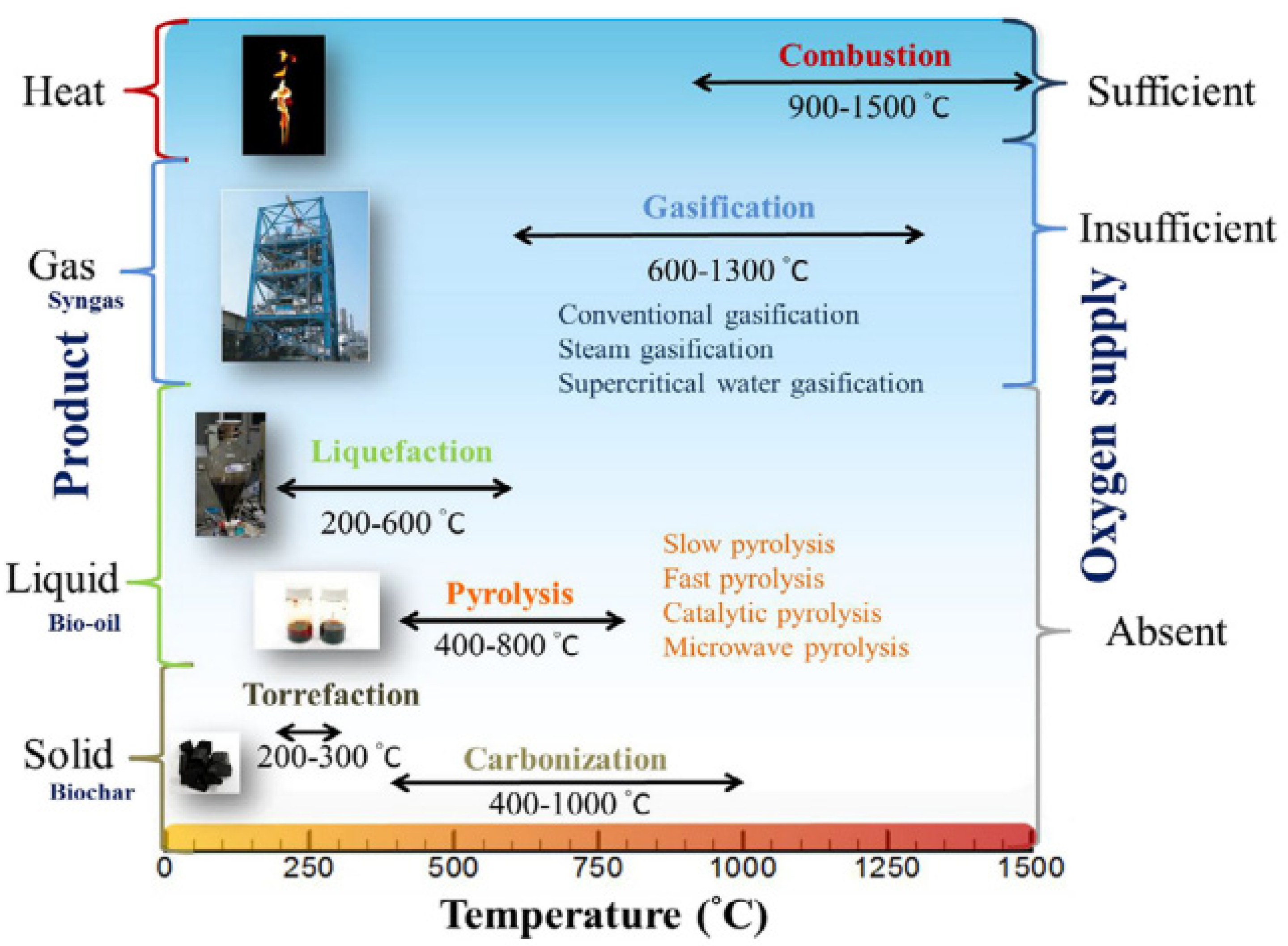
1.1. General Knowledge and History of Thermochemical Processes
- Gaseous fraction: non-condensing gases (NCG) that primarily comprise hydrogen, methane, carbon monoxide, carbon dioxide, and other gases in lower quantities.
- Liquid fraction: tars and/or oil and substances such as acetic acid, acetone, and methanol.
- Solid fraction: mainly pure carbon with some inert substances.
- Very high heating rates (~1000 °C/min) and heat exchange, which require a supply of raw material with a high degree of fragmentation (less than a few mm);
- Carefully controlled temperature in the gas phase reactor (approx. 500–650 °C);
- Short residence times, usually less than 2 s;
- Rapid cooling of gaseous pyrolysis products, leading to bio-oil as a key ingredient.
1.2. Torrefaction Background
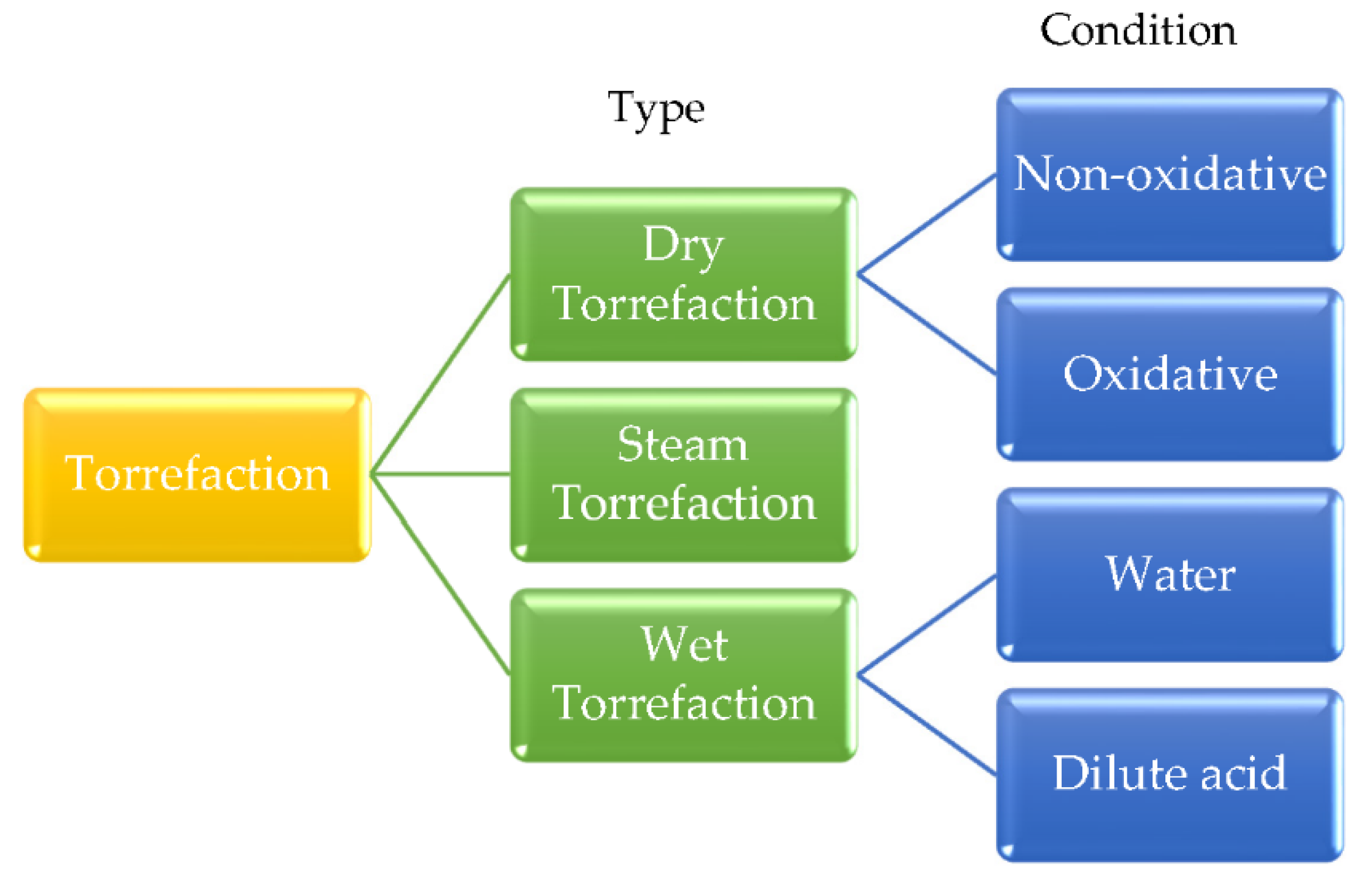
1.3. Various Types of Torrefaction
2. Review of Different Torrefaction Technologies
2.1. Initial List of Available Technologies on The Market
- Reactors in which the heating medium does not contain oxygen,
- Reactors in which the heating medium contains a small amount of oxygen,
- Other.
- Material flow;
- Heating mechanism of the substrate;
- Heat source;
- Torgas treatment [61].
- (1)
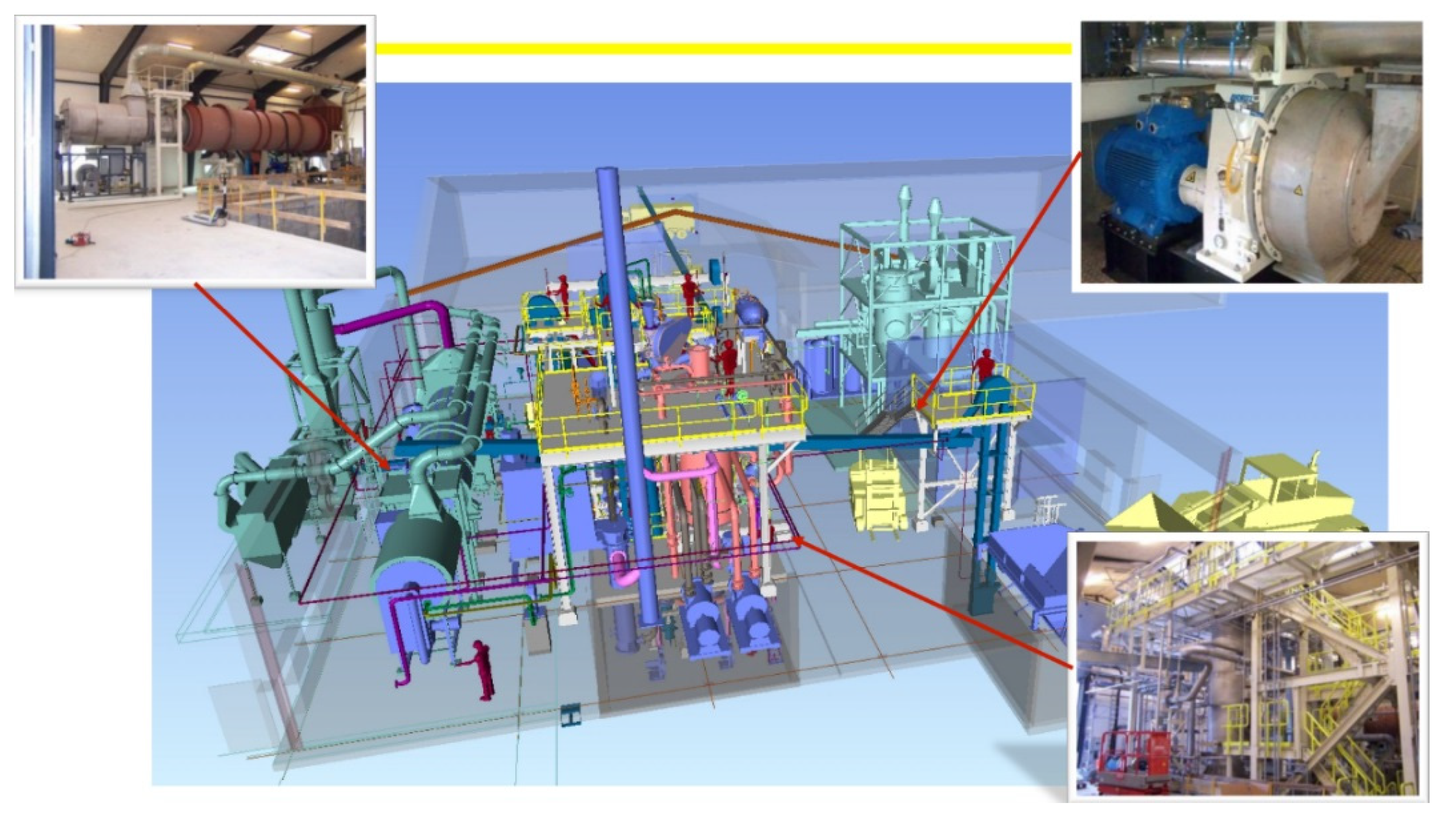
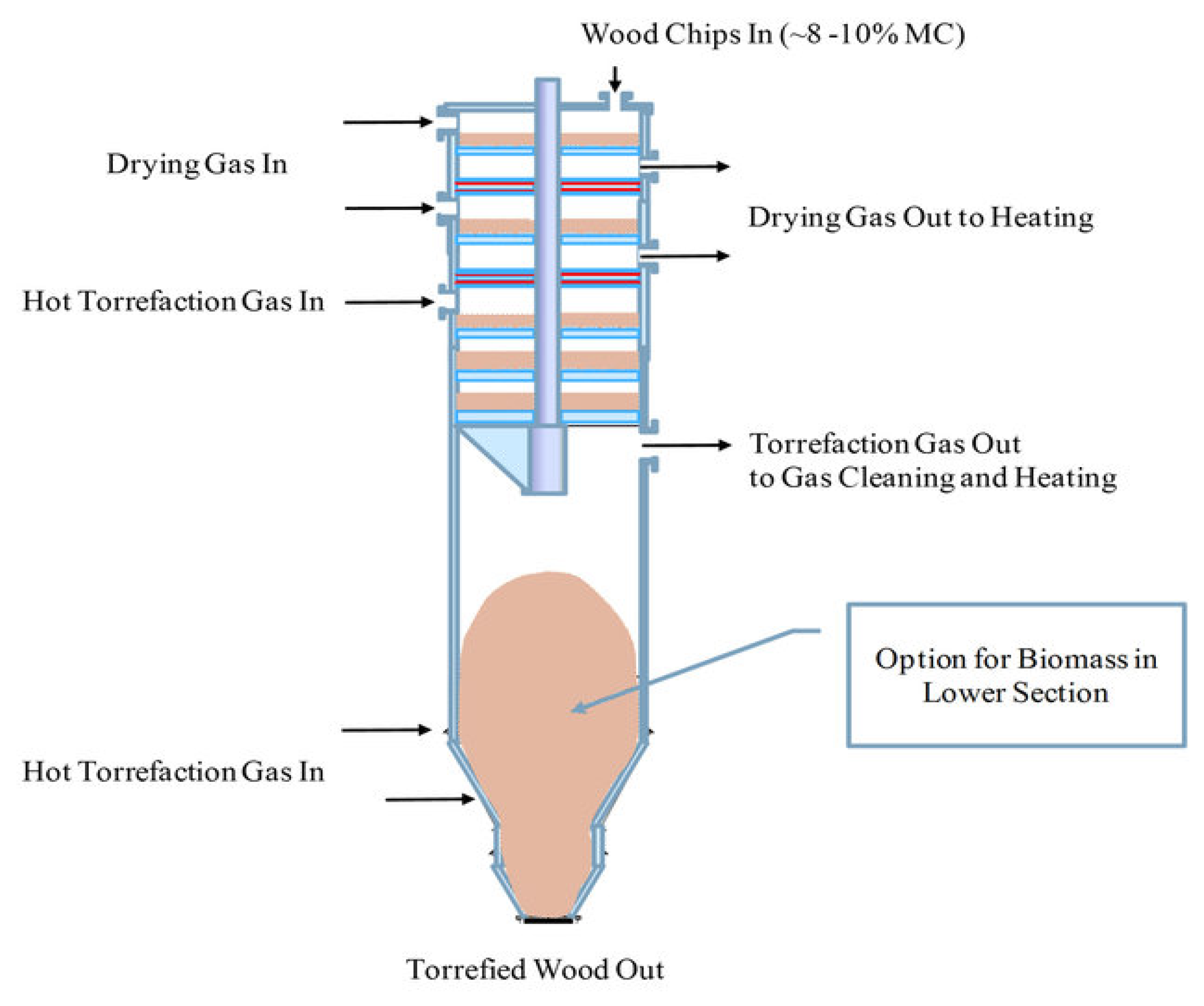
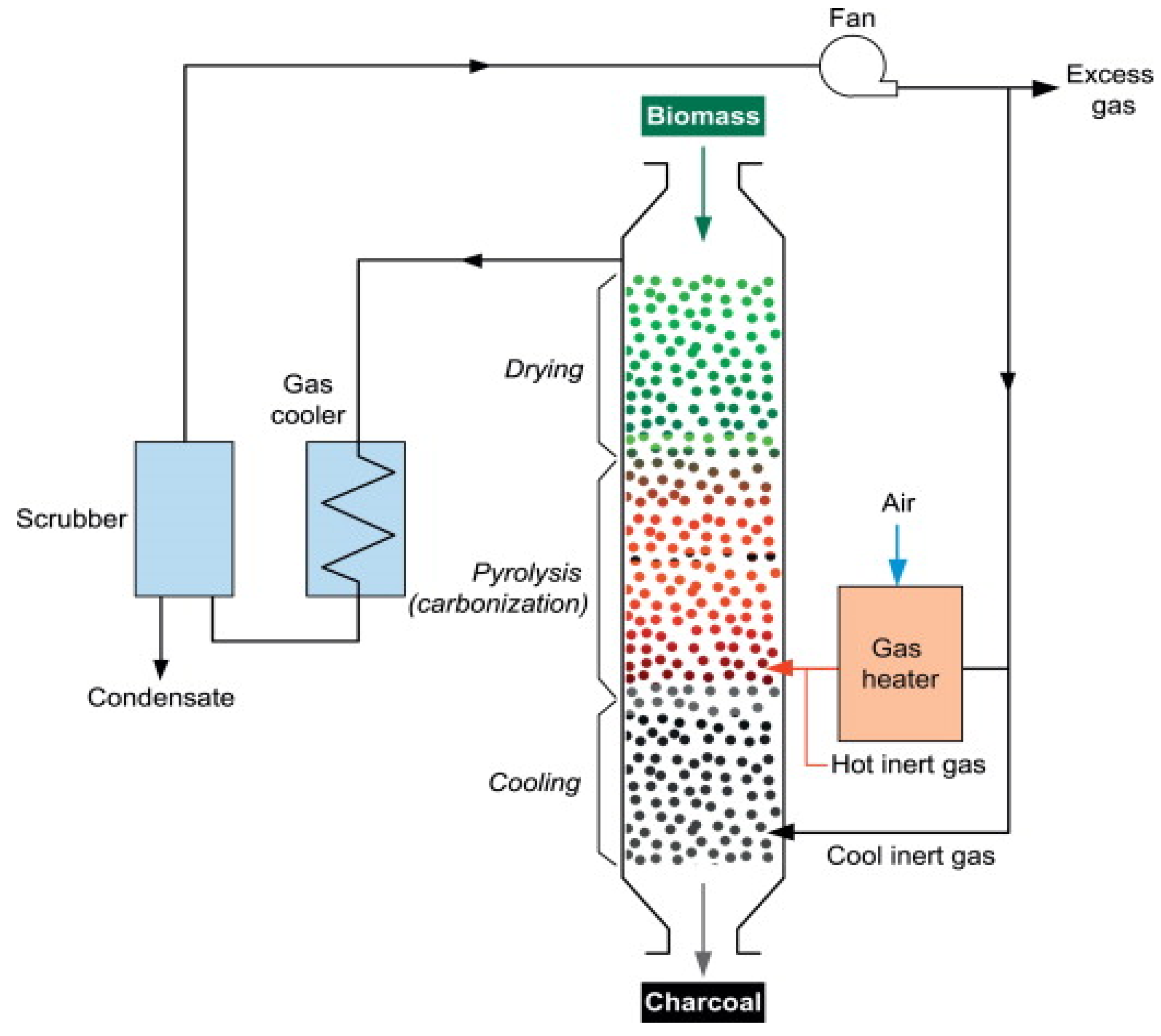
- Rotary drum reactor
- (2)
- Moving bed reactor
- (3)
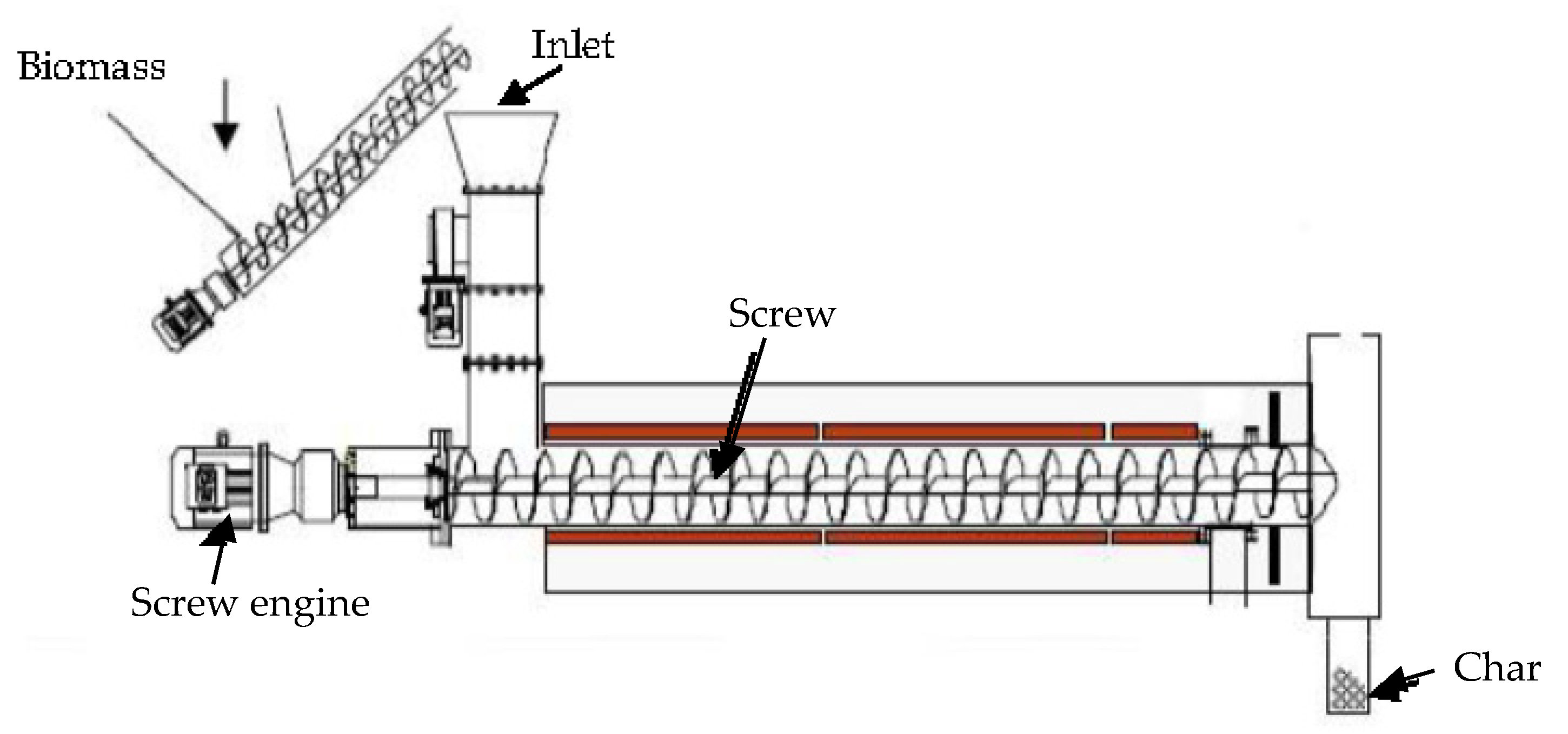
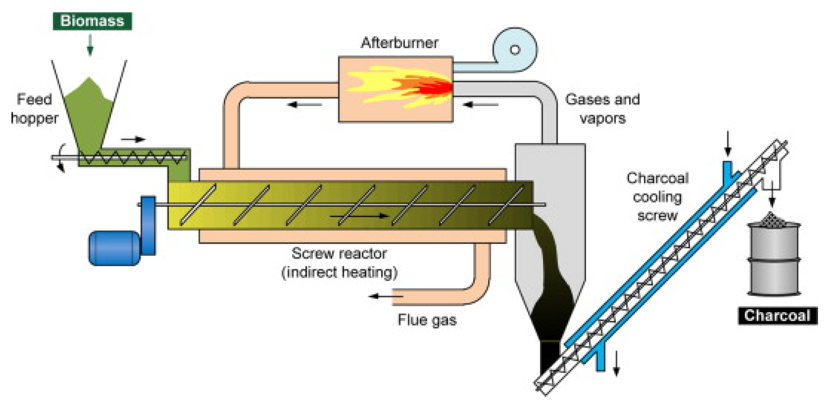
- Screw (Auger) reactor
- (4)
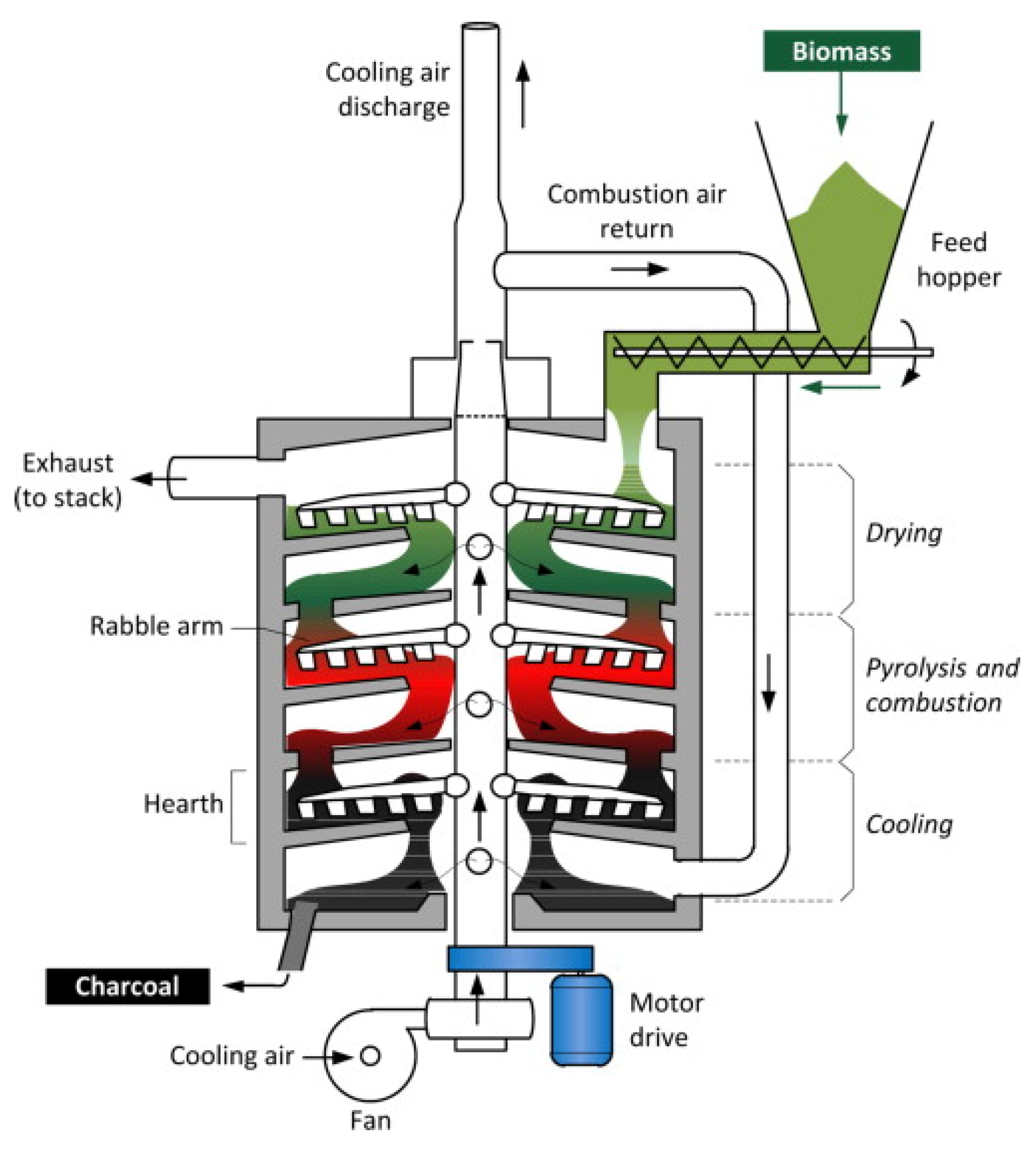
- Multiple hearth furnace with vertical baffles
- (5)
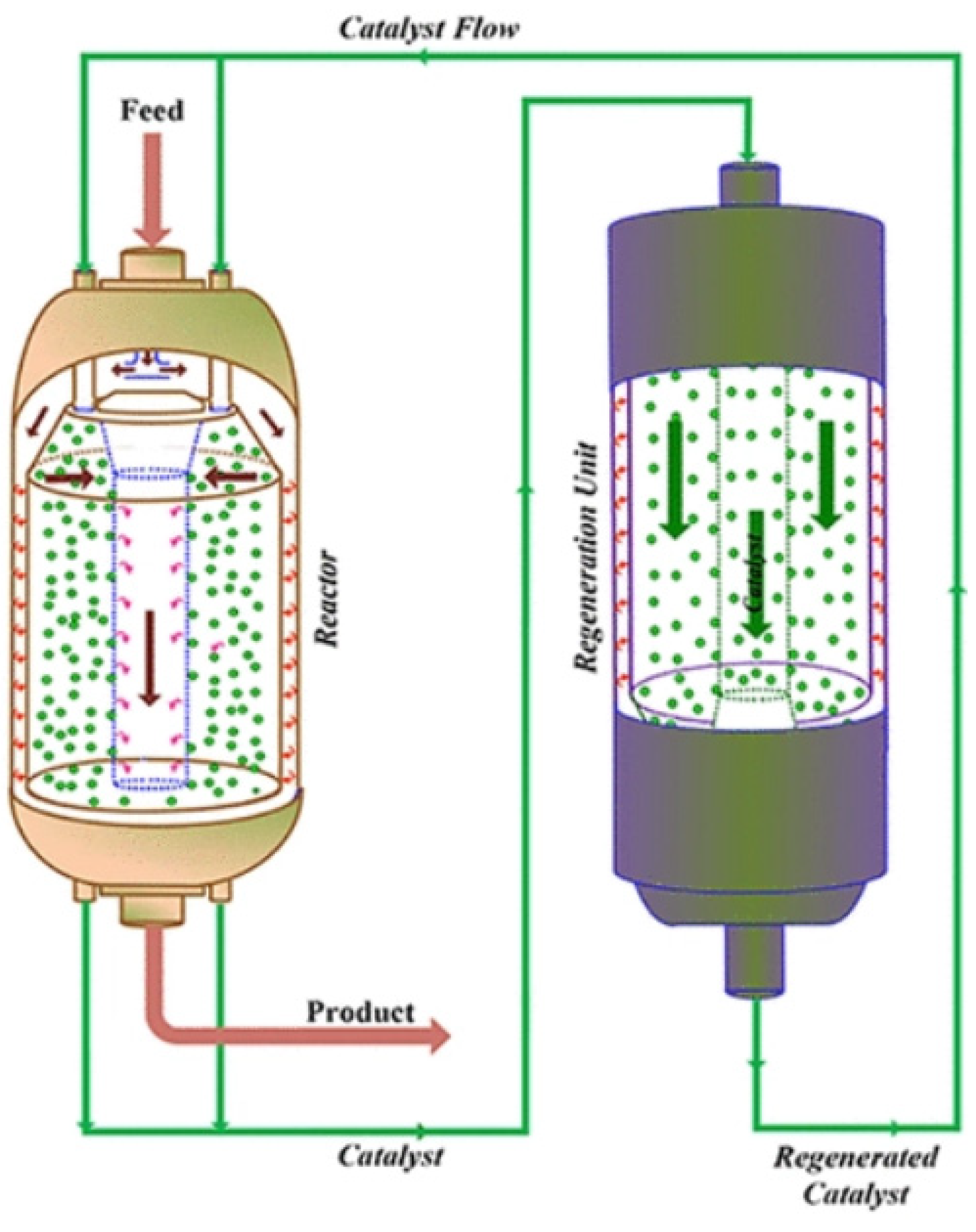
- Fluidized bed reactor
- (6)
- Torbed reactor

- (7)
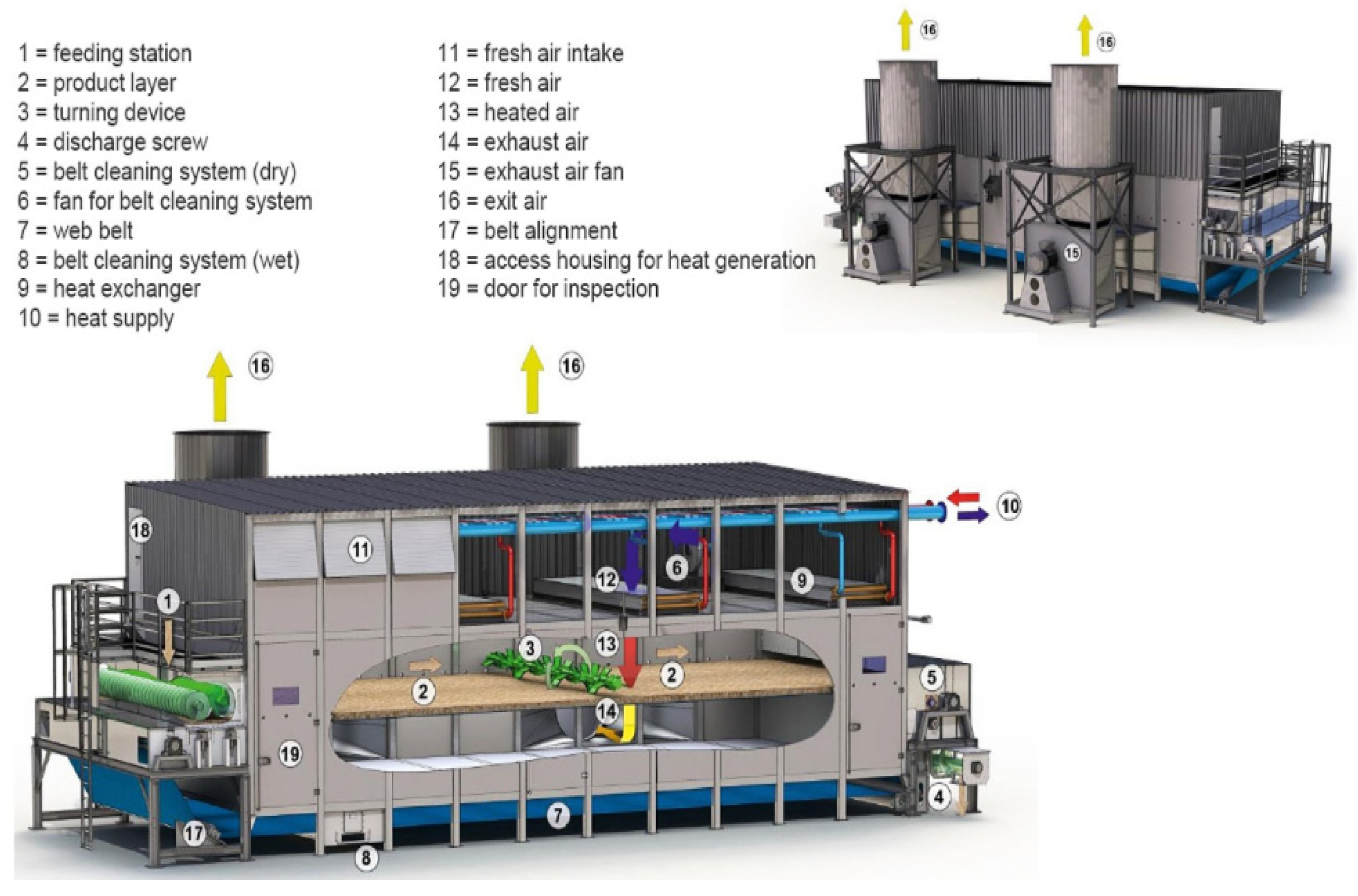
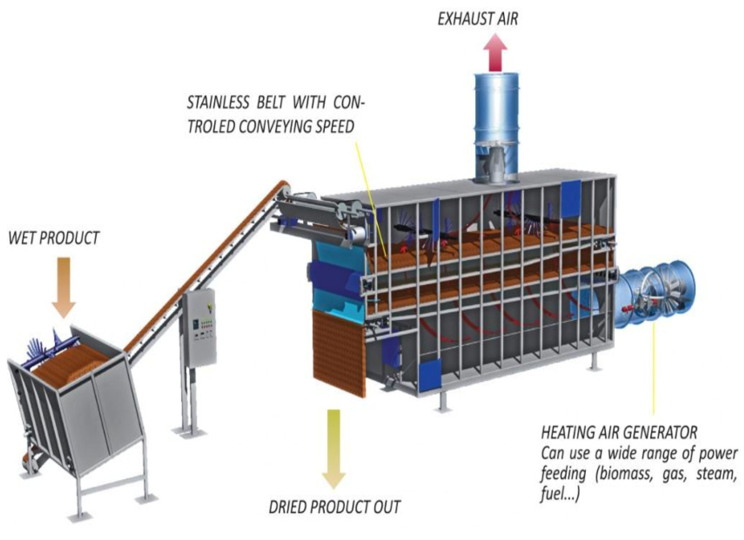
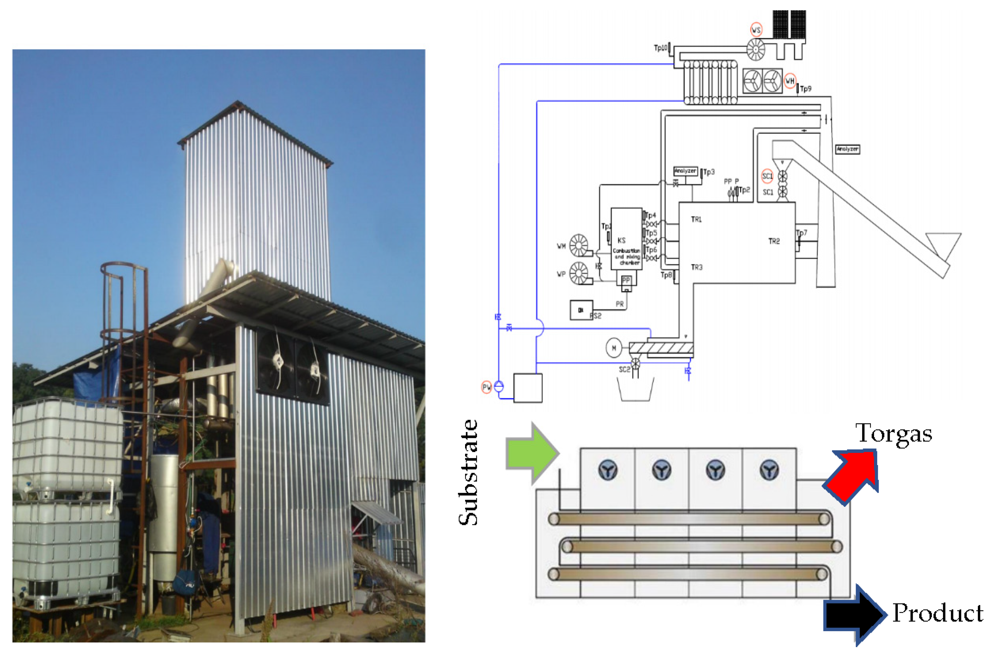
- Belt reactor with pre-drying
- (8)
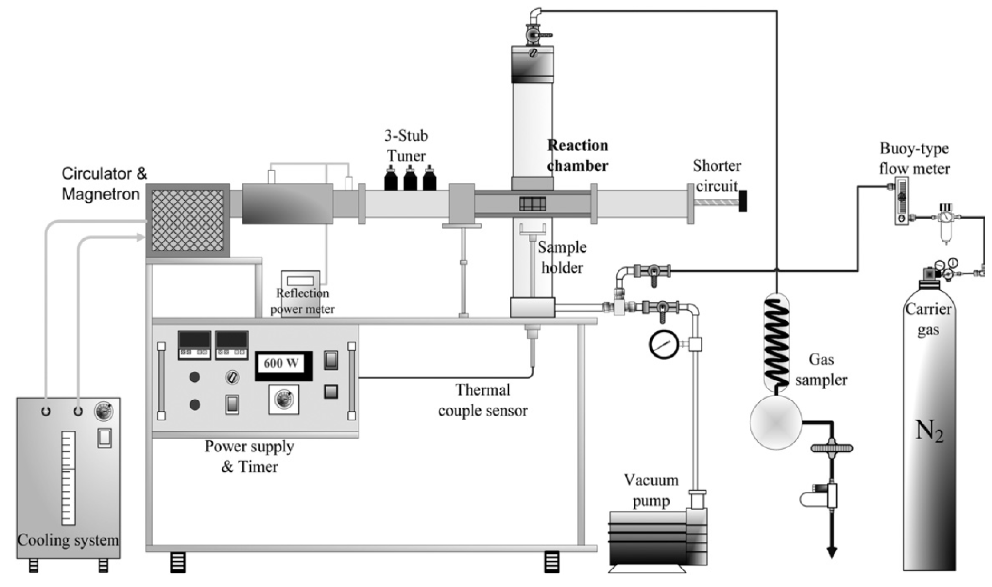
- Microwave reactor
- (9)
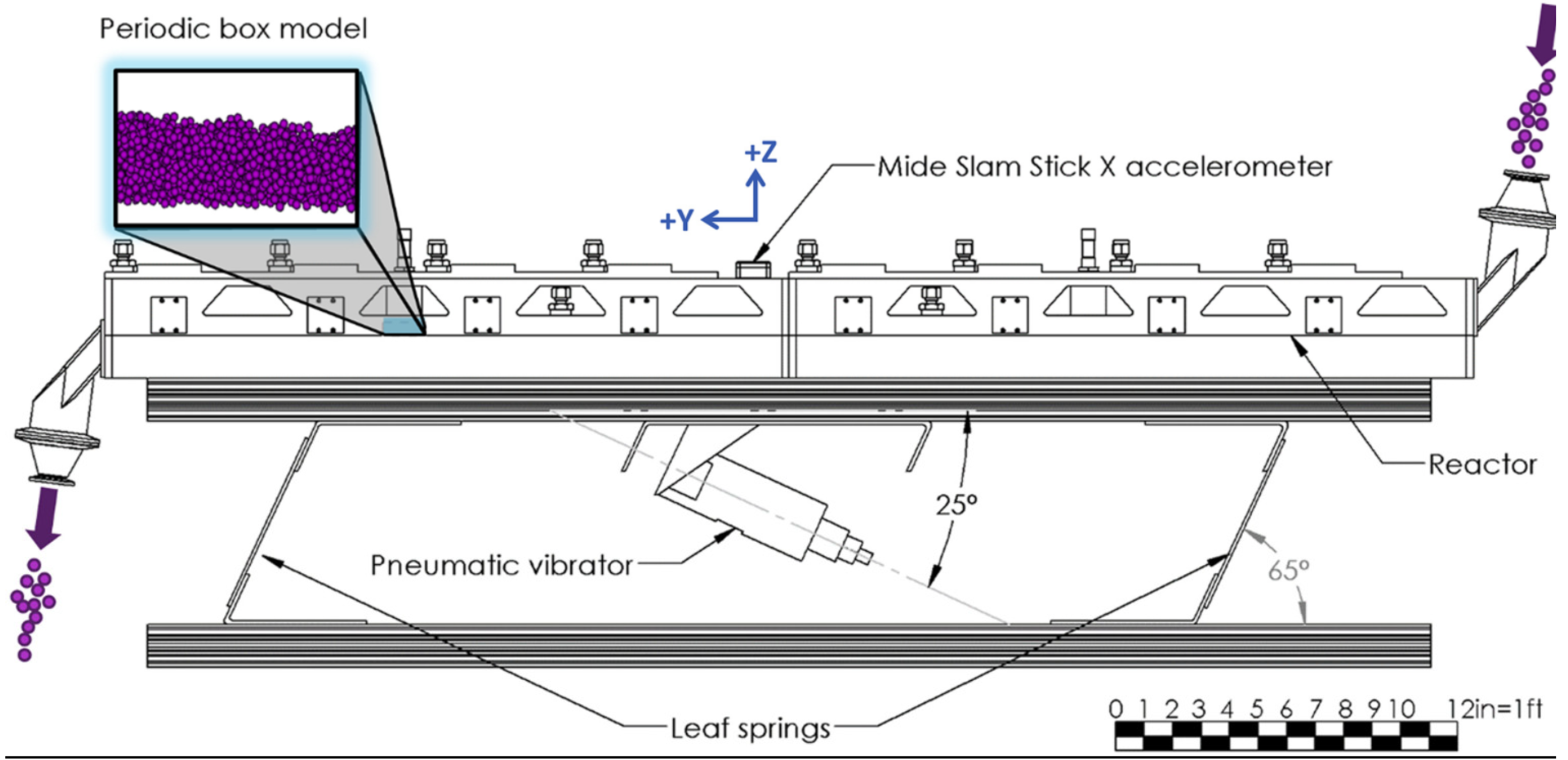
- Vibrating fluid bed reactor
- (10)
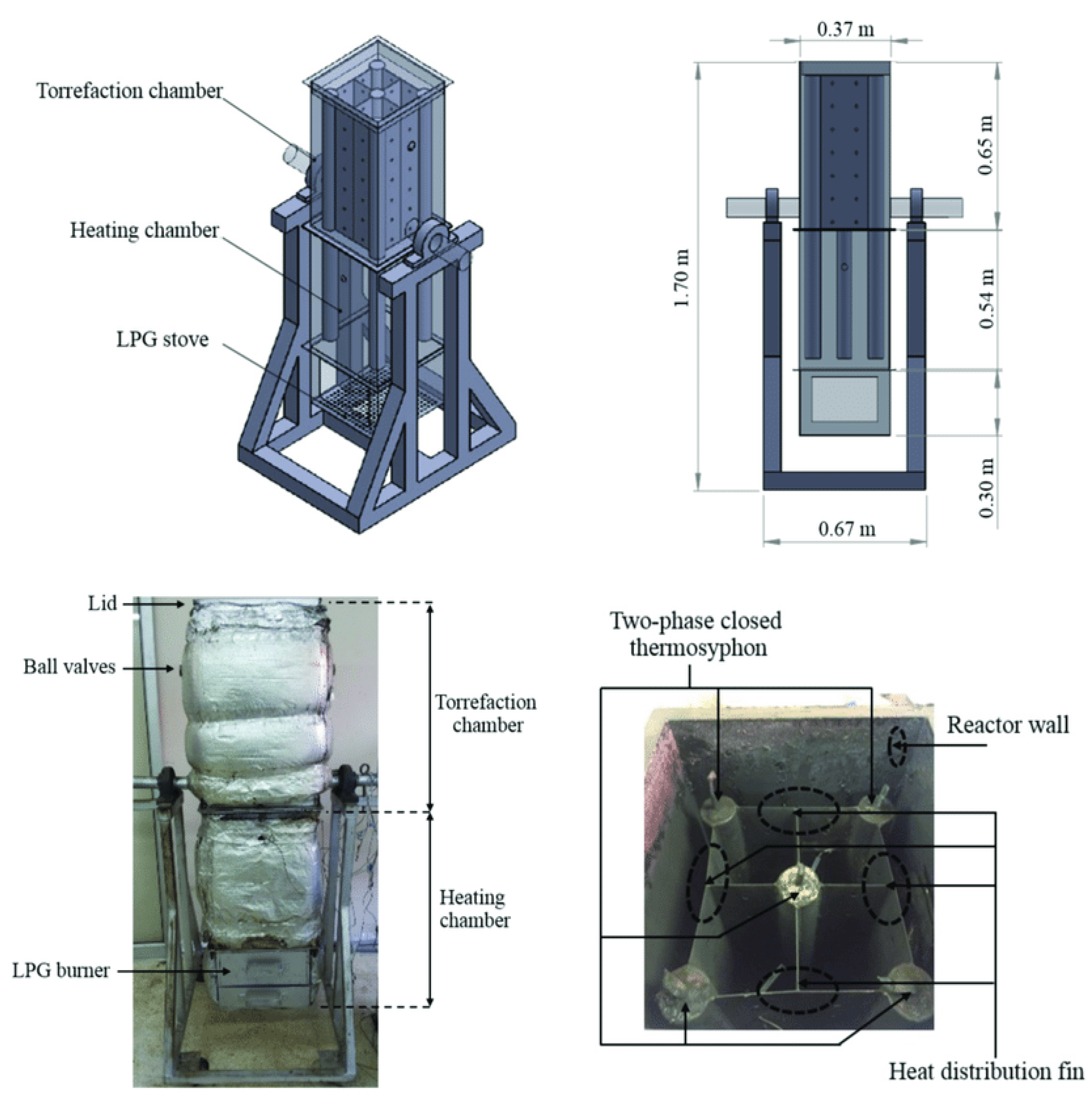
- Thermosiphon-fixed bed reactor
- (11)
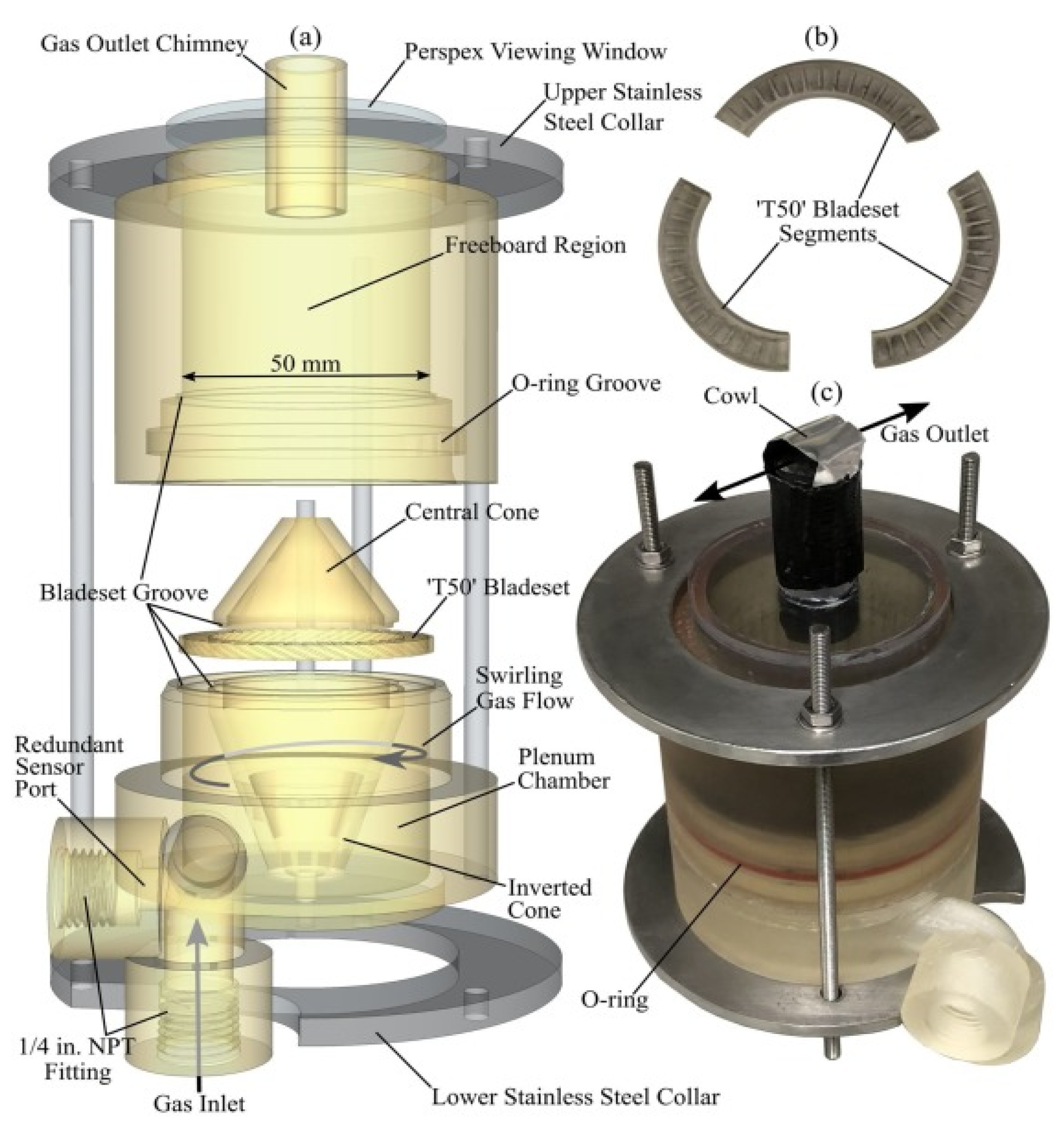
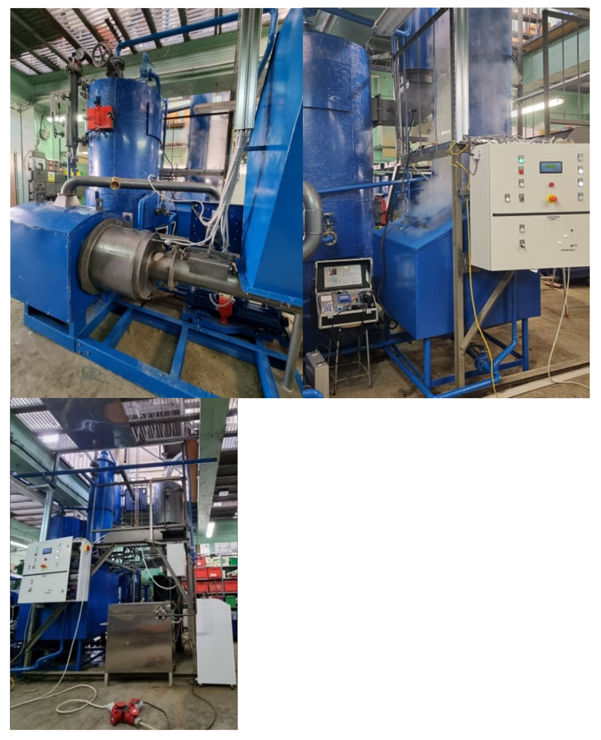
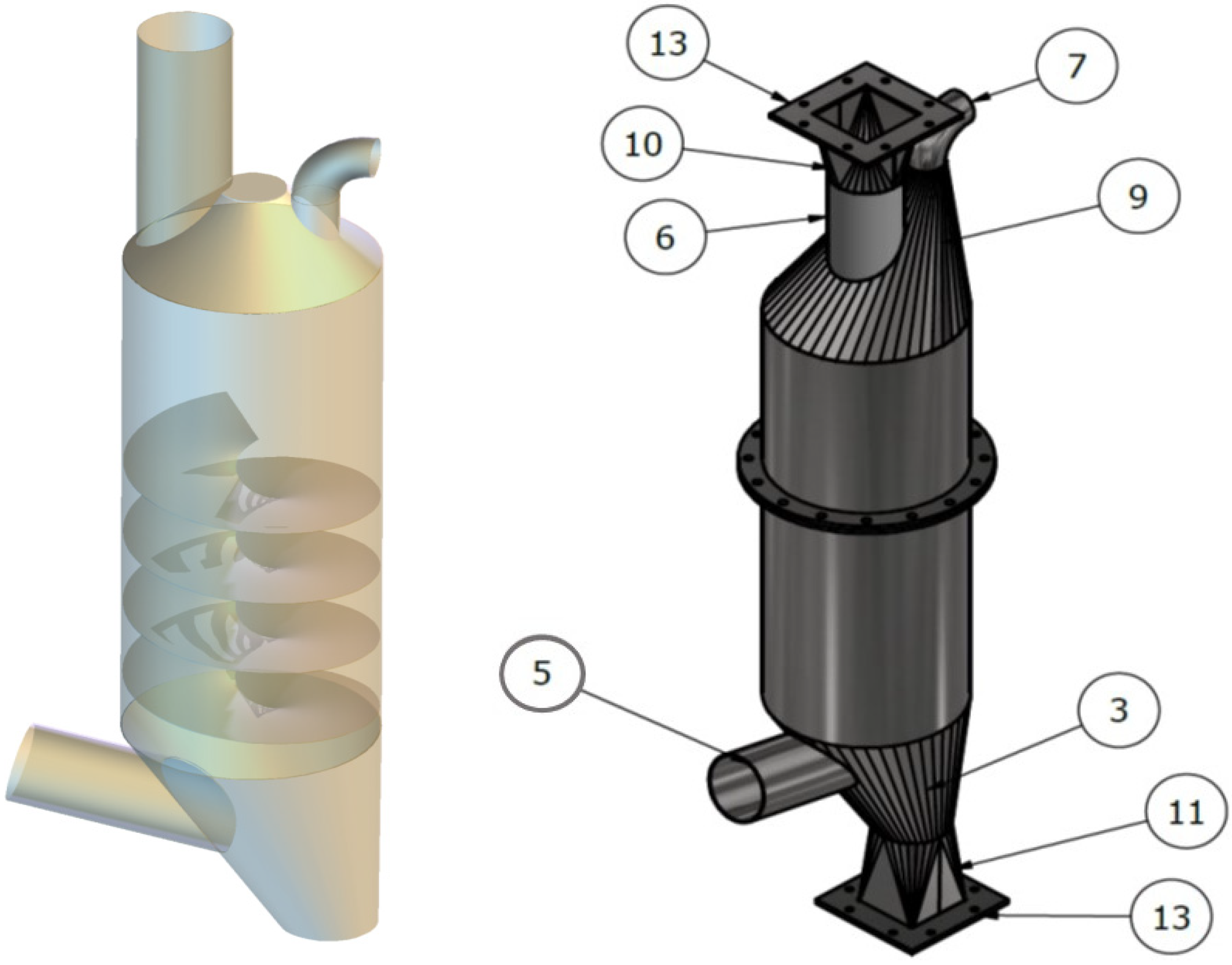
- Counter-Flow Torrefaction Reactor
2.2. Level of Innovation of Individual Technologies and Industrial Perspective
- (1)
- Rotary drum reactor
- (2)
- Moving bed reactor
- (3)
- Screw reactor
- (4)
- Multiple hearth furnace
- (5)
- Fluidized bed reactor (FBR)
- (6)
- Belt reactor with pre-drying
- (7)
- Torbed reactor
- (8)
- Vibrating bed reactor
- (9)
- Microwave reactor
3. Conclusions and Recommendations
Author Contributions
Funding
Institutional Review Board Statement
Informed Consent Statement
Data Availability Statement
Conflicts of Interest
References
- Szramowiat-Sala, K.; Korzeniewska, A.; Sornek, K.; Marczak, M.; Wierońska, F.; Berent, K.; Gołaś, J.; Filipowicz, M. The properties of particulate matter generated during wood combustion in in-use stoves. Fuel 2019, 253, 792–801. [Google Scholar] [CrossRef]
- Marczak, M.; Wierońska, F.; Burmistrz, P.; Strugała, A.; Kogut, K.; Lech, S. Investigation of subbituminous coal and lignite combustion processes in terms of mercury and arsenic removal. Fuel 2019, 251, 572–579. [Google Scholar] [CrossRef]
- Zhang, Y.; Cui, Y.; Chen, P.; Liu, S.; Zhou, N.; Ding, K.; Fan, L.; Peng, P.; Min, M.; Cheng, Y.; et al. Gasification Technologies and Their Energy Potentials. In Sustainable Resource Recovery and Zero Waste Approaches; Elsevier: Amsterdam, The Netherlands, 2019; pp. 193–206. [Google Scholar] [CrossRef]
- Ünyay, H.; Yılmaz, F.; Başar, İ.A.; Altınay Perendeci, N.; Çoban, I.; Şahinkaya, E. Effects of organic loading rate on methane production from switchgrass in batch and semi-continuous stirred tank reactor system. Biomass Bioenergy 2022, 156, 106306. [Google Scholar] [CrossRef]
- Szufa, S.; Wielgosiński, G.; Piersa, P.; Czerwińska, J.; Dzikuć, M.; Adrian, Ł.; Lewandowska, W.; Marczak, M. Torrefaction of Straw from Oats and Maize for Use as a Fuel and Additive to Organic Fertilizers—TGA Analysis, Kinetics as Products for Agricultural Purposes. Energies 2020, 13, 2064. [Google Scholar] [CrossRef] [Green Version]
- Parthasarathy, P.; Narayanan, K.S. Hydrogen production from steam gasification of biomass: Influence of process parameters on hydrogen yield—A review. Renew. Energy 2014, 66, 570–579. [Google Scholar] [CrossRef]
- Kondo, H.; Owen, L.A. 5.12 Paleoseismology. In Treatise on Geomorphology; Elsevier: Amsterdam, The Netherlands, 2013; pp. 267–299. [Google Scholar] [CrossRef]
- Ghosh, P.; Sengupta, S.; Singh, L.; Sahay, A. Life cycle assessment of waste-to-bioenergy processes: A review. Bioreactors 2020, 8, 105–122. [Google Scholar] [CrossRef]
- Adrian, Ł.; Piersa, P.; Szufa, S.; Cebula, A.; Kowalczyk, S. Experimental Research and Thermographic Analysis of Heat Transfer Processes in a Heat Pipe Heat Exchanger Utilizing as a Working Fluid R134A. In Renewable Energy Sources: Engineering, Technology, Innovation; Springer: Cham, Switzerland, 2018; pp. 413–421. [Google Scholar] [CrossRef]
- Isahak, W.N.R.W.; Hisham, M.W.M.; Yarmo, M.A.; Yun Hin, T.Y. A review on bio-oil production from biomass by using pyrolysis method. Renew. Sustain. Energy Rev. 2012, 16, 5910–5923. [Google Scholar] [CrossRef]
- Szufa, S.; Piersa, P.; Adrian, Ł.; Sielski, J.; Grzesik, M.; Romanowska-Duda, Z.; Piotrowski, K.; Lewandowska, W. Acquisition of Torrefied Biomass from Jerusalem Artichoke Grown in a Closed Circular System Using Biogas Plant Waste. Molecules 2020, 25, 3862. [Google Scholar] [CrossRef]
- Chen, W.-H.; Lin, B.-J.; Lin, Y.-Y.; Chu, Y.-S.; Ubando, A.T.; Show, P.L.; Ong, H.C.; Chang, J.-S.; Ho, S.-H.; Culaba, A.B.; et al. Progress in biomass torrefaction: Principles, applications and challenges. Prog. Energy Combust. Sci. 2021, 82, 100887. [Google Scholar] [CrossRef]
- Jenkins, R.W.; Sutton, A.D.; Robichaud, D.J. Pyrolysis of Biomass for Aviation Fuel. In Biofuels forAviation; Elsevier: Amsterdam, The Netherlands, 2016; pp. 191–215. [Google Scholar] [CrossRef]
- Nunes, L.J.R.; De Oliveira Matias, J.C.; Da Silva Catalão, J.P. Torrefaction of Biomass for Energy Applications; Elsevier: Amsterdam, The Netherlands, 2017. [Google Scholar] [CrossRef]
- Hohn, E. Article on the Theory of Drying and Torrefaction; Springer: Berlin/Heidelberg, Germany, 1919; Volume 63, pp. 821–826. [Google Scholar]
- Emrich, W. Handbook of Charcoal Making. Solar Energy R&D in the European Community; Series E, Energy from Biomass; Springer: Dordrecht, The Netherlands, 1985; Volume 7. [Google Scholar]
- Bourgeois, J.P.; Doat, J. Torrefied wood from temperate and tropical species. Advantages and prospects. In Proceedings of the Bioenergy 84, Volume III. Biomass Conversion, Goteborg, Sweden, 15–21 June 1984; Elsevier Applied Science Publishers: Amsterdam, The Netherlands, 1984. [Google Scholar]
- Arjona, J.; Rios, G.; Gibert, H.; Vincent, J. Gas-Fluidized Bed Torrefaction of Coffee. Cafe Cacao 1979, 23, 119–228. [Google Scholar]
- Miele, A.E. Method and System for the Torrefaction of Lignocellulosic Material. Available online: https://patents.google.com/patent/EP2758501A2/en (accessed on 5 February 2022).
- Felfli, F.; Luengo, C.; Beaton, P.; Suarez, J. Efficiency test for bench unit torrefaction and characterization of torrefied biomass. In Proceedings of the Fourth Biomass Conference of the Americas, Oakland, CA, USA, 29 August–2 September 1999; pp. 589–592. [Google Scholar]
- Felfli, F.; Luengo, C.; Bezzon, G.; Soler, P.; Mora, W. A Numerical Model for Biomass Torrefaction. In Proceedings of the 10th European Conference and Technology Exhibition Biomass for Energy and Industry, Wurzburg, Germany, 8–11 June 1998; pp. 1596–1599. [Google Scholar]
- Felfli, F.; Luengo, C.; Bezzon, G.; Soler, P. Bench unit for biomass residues torrefaction. In Proceedings of the 10th European Conference and Technology Exhibition Biomass for Energy and Industry, Wurzburg, Germany, 8–11 June 1998; pp. 1593–1595. [Google Scholar]
- Lehrfeld, J. Cation Exchange Resins Prepared by Torrefaction of Phytic Acid with Some Agricultural Residues. Abstr. Pap. Am. Chem. Soc. 1997, 23, 47. [Google Scholar]
- Pentananunt, R.; Rahman, A.N.M.M.; Bhattacharya, S.C. Upgrading of biomass by means of torrefaction. Energy 1990, 15, 1175–1179. [Google Scholar] [CrossRef]
- Szufa, S.; Adrian, Ł.; Piersa, P.; Romanowska-Duda, Z.; Grzesik, M.; Cebula, A.; Kowalczyk, S. Experimental studies on energy crops torrefaction process using batch reactor to estimate torrefaction temperature and residence time. In Renewable Energy Sources: Engineering, Technology, Innovation; Mudryk, K., Werle, S., Eds.; Springer: Berlin/Heidelberg, Germany, 2018; pp. 365–373. [Google Scholar] [CrossRef]
- Szufa, S.; Piersa, P.; Adrian, Ł; Czerwińska, J.; Lewandowski, A.; Lewandowska, W.; Sielski, J.; Dzikuć, M.; Wróbel, M.; Jewiarz, M.; et al. Sustainable Drying and Torrefaction Processes of Miscanthus for Use as a Pelletized Solid Biofuel and Biocarbon-Carrier for Fertilizers. Molecules 2021, 26, 1014. [Google Scholar] [CrossRef]
- Dutta, A.; Leon, M.A. Pros and Cons of Torrefaction of Woody Biomass; University of Guelph: Guelph, ON, Canada, 2006; pp. 1–19. [Google Scholar]
- Başar, I.A.; Çoban, Ö.; Göksungur, M.Y.; Eskicioğlu, Ç; Perendeci, N.A. Enhancement of lignocellulosic biomass anaerobic digestion by optimized mild alkaline hydrogen peroxide pretreatment for biorefinery applications. J. Environ. Manag. 2021, 298, 113539. [Google Scholar] [CrossRef]
- Başar, I.; Ünşar, E.K.; Ünyay, H.; Perendeci, N. Ethanol, methane, or both? Enzyme dose impact on ethanol and methane production from untreated energy crop switchgrass varieties. Renew. Energy 2019, 149, 287–297. [Google Scholar] [CrossRef]
- Başar, I.A.; Perendeci, N.A. Optimization of zero-waste hydrogen peroxide—Acetic acid pretreatment for sequential ethanol and methane production. Energy 2021, 225, 120324. [Google Scholar] [CrossRef]
- Duranay, N.D.; Akkuş, G. Solid fuel production with torrefaction from vineyard pruning waste. Biomass Convers. Biorefinery 2021, 11, 2335–2346. [Google Scholar] [CrossRef]
- Ramos-Carmona, S.; Pérez, J.F.; Pelaez-Samaniego, M.R.; Barrera, R.; Garcia-Perez, M. Effect of torrefaction temperature on properties of Patula pine. Maderas Cienc. y Tecnol. 2017, 19, 39–50. [Google Scholar] [CrossRef] [Green Version]
- Kymäläinen, M.; Havimo, M.; Keriö, S.; Kemell, M.; Solio, J. Biological degradation of torrefied wood and charcoal. Biomass Bioenergy 2014, 71, 170–177. [Google Scholar] [CrossRef]
- Chen, W.-H.; Lin, B.-J.; Colin, B.; Pétrissans, A.; Pétrissans, M. A study of hygroscopic property of biomass pretreated by torrefaction. Energy Procedia 2019, 158, 32–36. [Google Scholar] [CrossRef]
- Sá, L.C.R.; Loureiro, L.M.E.F.; Nunes, L.J.R.; Mendes, A.M. Torrefaction as a Pretreatment Technology for Chlorine Elimination from Biomass: A Case Study Using Eucalyptus globulus Labill. Resources 2020, 9, 54. [Google Scholar] [CrossRef]
- Piersa, P.; Szufa, S.; Czerwińska, J.; Unyay, H.; Adrian, Ł.; Wielgosinski, G.; Obraniak, A.; Lewandowska, W.; Marczak-Grzesik, M.; Dzikuć, M.; et al. Pine Wood and Sewage Sludge Torrefaction Process for Production Renewable Solid Biofuels and Biochar as Carbon Carrier for Fertilizers. Energies 2021, 14, 8176. [Google Scholar] [CrossRef]
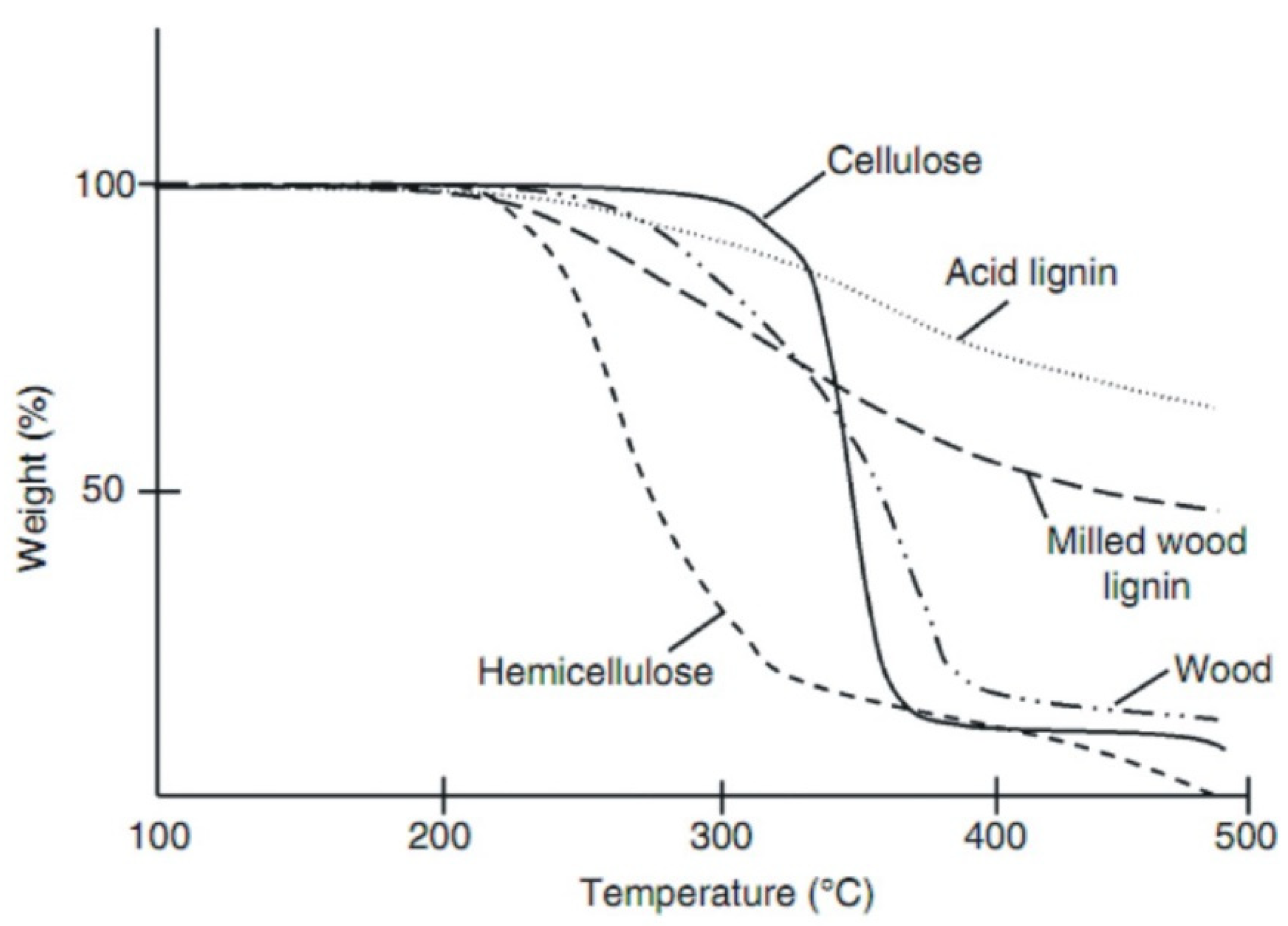
- Shafizadeh, F.; McGinnis, G. Chemical composition and thermal analysis of cottonwood. Carbohydr. Res. 1971, 16, 273–277. [Google Scholar] [CrossRef]
- Cao, X.; Ro, K.S.; Libra, J.A.; Kammann, C.I.; Lima, I.; Berge, N.; Li, L.; Li, Y.; Chen, N.; Yang, J.; et al. Effects of Biomass Types and Carbonization Conditions on the Chemical Characteristics of Hydrochars. J. Agric. Food Chem. 2013, 61, 9401–9411. [Google Scholar] [CrossRef] [PubMed]
- Grycova, B.; Pryszcz, A.; Krzack, S.; Klinger, M.; Lestinsky, P. Torrefaction of biomass pellets using the thermogravimetric analyser. Biomass Convers. Biorefinery 2020, 11, 2837–2842. [Google Scholar] [CrossRef]
- Granados, D.A.; Basu, P.; Chejne, F.; Nhuchhen, D.R. Detailed Investigation into Torrefaction of Wood in a Two-Stage Inclined Rotary Torrefier. Energy Fuels 2016, 31, 647–658. [Google Scholar] [CrossRef]
- Poudel, J.; Karki, S.; Oh, S. Valorization of Waste Wood as a Solid Fuel by Torrefaction. Energies 2018, 11, 1641. [Google Scholar] [CrossRef] [Green Version]
- Acharya, B.; Dutta, A.; Minaret, J. Review on comparative study of dry and wet torrefaction. Sustain. Energy Technol. Assess. 2015, 12, 26–37. [Google Scholar] [CrossRef]
- Romanowska-Duda, Z.; Szufa, S.; Grzesik, M.; Piotrowski, K.; Janas, R. The Promotive Effect of Cyanobacteria and Chlorella sp. Foliar Biofertilization on Growth and Metabolic Activities of Willow (Salix viminalis L.) Plants as Feedstock Production, Solid Biofuel and Biochar as C Carrier for Fertilizers via Torrefaction Process. Energies 2021, 14, 5262. [Google Scholar] [CrossRef]
- Yang, W.; Wu, S.; Wang, H.; Ma, P.; Shimanouchi, T.; Kimura, Y.; Zhou, J. Effect of wet and dry torrefaction process on fuel properties of solid fuels derived from bamboo and Japanese cedar. BioResources 2017, 12, 8629–8640. [Google Scholar] [CrossRef]
- Szufa, S. Zastosowanie przegrzanej pary w procesie toryfikacji biomasy. Przemysł Chem. 2020, 1, 123–127. [Google Scholar] [CrossRef]
- Ibbett, R.; Gaddipati, S.; Davies, S.; Hill, S.; Tucker, G. The mechanisms of hydrothermal deconstruction of lignocellulose: New insights from thermal–analytical and complementary studies. Bioresour. Technol. 2011, 102, 9272–9278. [Google Scholar] [CrossRef] [PubMed] [Green Version]
- Garrote, G.; Domínguez, H.; Parajó, J.C. Hydrothermal processing of lignocellulosic materials. Holz Als Roh-Und Werkst. 1999, 57, 191–202. [Google Scholar] [CrossRef]
- Wielgosiński, G.; Czerwińska, J.; Szufa, S. Municipal Solid Waste Mass Balance as a Tool for Calculation of the Possibility of Implementing the Circular Economy Concept. Energies 2021, 14, 1811. [Google Scholar] [CrossRef]
- Libra, J.A.; Ro, K.S.; Kammann, C.; Funke, A.; Berge, N.D.; Neubauer, Y.; Titirici, M.-M.; Fühner, C.; Bens, O.; Kern, J.; et al. Hydrothermal carbonization of biomass residuals: A comparative review of the chemistry, processes and applications of wet and dry pyrolysis. Biofuels 2011, 2, 71–106. [Google Scholar] [CrossRef] [Green Version]
- Kambo, H.S.; Dutta, A. A comparative review of biochar and hydrochar in terms of production, physico-chemical properties and applications. Renew. Sustain. Energy Rev. 2015, 45, 359–378. [Google Scholar] [CrossRef]
- Funke, A.; Reebs, F.; Kruse, A. Experimental comparison of hydrothermal and vapothermal carbonization. Fuel Process. Technol. 2013, 115, 261–269. [Google Scholar] [CrossRef]
- Tumuluru, J.S.; Wright, C.T.; Hess, J.R.; Kenney, K.L. A review of biomass densification systems to develop uniform feedstock commodities for bioenergy application. Biofuels Bioprod. Biorefin. 2011, 5, 683–707. [Google Scholar] [CrossRef]
- Reza, M.T.; Lynam, J.; Uddin, M.H.; Coronella, C.J. Hydrothermal carbonization: Fate of inorganics. Biomass Bioenergy 2013, 49, 86–94. [Google Scholar] [CrossRef]
- Yan, W.; Acharjee, T.C.; Coronella, C.J.; Vásquez, V.R. Thermal pretreatment of lignocellulosic biomass. Environ. Prog. Sustain. Energy 2009, 28, 435–440. [Google Scholar] [CrossRef]
- Tumuluru, J.S.; Sokhansanj, S.; Wright, C.T.; Richard, D. Boardman. Biomass Torrefaction Process Review and Moving Bed Torrefaction System Model Development; U.S. Department of Energy Office of Scientific and Technical Information: Idaho Falls, ID, USA, 2010. [Google Scholar] [CrossRef] [Green Version]
- Hoekman, S.K.; Broch, A.; Robbins, C. Hydrothermal Carbonization (HTC) of Lignocellulosic Biomass. Energy Fuels 2011, 25, 1802–1810. [Google Scholar] [CrossRef]
- Mustaza, M.N.F.; Mizan, M.N.; Yoshida, H.; Izhar, S. Torréfaction of Mangrove Wood by Introducing Superheated Steam for Biochar Production. IOP Conf. Ser. Earth Environ. Sci. 2021, 765, 012027. [Google Scholar] [CrossRef]
- Zhang, D.; Chen, X.; Qi, Z.; Wang, H.; Yang, R.; Lin, W.; Li, J.; Zhou, W.; Ronsse, F. Superheated steam as carrier gas and the sole heat source to enhance biomass torrefaction. Bioresour. Technol. 2021, 331, 124955. [Google Scholar] [CrossRef]
- Adrian, Ł.; Szufa, S.; Piersa, P.; Mikołajczyk, F. Numerical Model of Heat Pipes as an Optimization Method of Heat Exchangers. Energies 2021, 14, 7647. [Google Scholar] [CrossRef]
- Organic Waste Torrefaction—A Review: Reactor Systems, and the Biochar Properties. Available online: https://www.intechopen.com/chapters/54381 (accessed on 5 February 2022).
- Stępień, P. Mathematical modeling of torrefaction of refuse-derived alternative fuel Modelowanie matematyczne toryfikacji paliwa pochodzącego z odpadów. Chem. Ind. 2017, 96, 227–231. [Google Scholar] [CrossRef]
- Stępień, P.; Mysior, M.; Białowiec, A. Problemy Techniczne i Technologiczne oraz Potencjał Aplikacyjny Toryfikacji Odpadów; Wrocław Wydaw Uniw Wrocławskiego: Wrocław, Poland, 2018; pp. 59–78. [Google Scholar]
- Eriksson, A.M. Torrefaction and gasification of biomass. The Potential of Torrefaction Combined with Entrained Flow Gasification. Ph.D. Thesis, KTH Royal Institute of Technology Stockholm, Stockholm, Sweden, 2012. [Google Scholar]
- Cahyanti, M.N.; Doddapaneni, T.R.K.C.; Kikas, T. Biomass torrefaction: An overview on process parameters, economic and environmental aspects and recent advancements. Bioresour. Technol. 2020, 301, 122737. [Google Scholar] [CrossRef]
- Alok, D. Torrefaction of Biomass. Master’s Thesis, Dalhousie University, Halifax, NS, Canada, 2011. [Google Scholar]
- Eyre, A. Torrefaction Demonstration Plants. Master’s Thesis, Dalhousie University, Halifax, NS, Canada, 2012; p. 27. [Google Scholar]
- Wilèn, C.; Jukola, P.; Järvinen, T.; Sipilä, K.; Verhoeff, F.; Kiel, J. Wood Torrefaction—Pilot Tests and Utilisation; VTT: Espoo, Finland, 2013; Volume 122. [Google Scholar]
- Verhoeff FAdell i Arnuelos, A.; Boersma, A.R.; Pels, J.R.; Lensselink, J.; Kiel, J.H.A.; Schukken, H. Torrefaction Technology for the Production of Solid Bioenergy Carriers from Biomass and Waste. 2011. Available online: https://www.torrcoal.com/cms/wp-content/uploads/Torrefaction-Technology-for-solid-bioenergy-carriers-from-biomass-and-waste.pdf (accessed on 5 February 2022).
- Koppejan, J.; Sokhansanj, S.; Melin, S.; Madrali, S. Status overview of torrefaction technologies (IEA Bioenergy Task 32). IEA Bioenergy Task 2012, 32, 1–54. [Google Scholar]
- Negi, S.; Jaswal, G.; Dass, K.; Mazumder, K.; Elumalai, S.; Roy, J.K. Torrefaction: A sustainable method for transforming of agri-wastes to high energy density solids (biocoal). Rev. Environ. Sci. Biotechnol. 2020, 19, 463–488. [Google Scholar] [CrossRef]
- Shirzad, M.; Karimi, M.; Silva, J.A.C.; Rodrigues, A.E. Moving Bed Reactors: Challenges and Progress of Experimental and Theoretical Studies in a Century of Research. Ind. Eng. Chem. Res. 2019, 58, 9179–9198. [Google Scholar] [CrossRef] [Green Version]
- Ronsse, F.; Nachenius, R.W.; Prins, W. Carbonization of Biomass. In Recent Advances in Thermo-Chemical Conversion of Biomass; Elsevier: Amsterdam, The Netherlands, 2015; pp. 293–324. [Google Scholar] [CrossRef]
- Bergman, P.C.A.; Boersma, A.R.; Zwart, R.W.R.; Kiel, J.H.A. Torrefaction for Biomass Co-Firing in Existing Coal-Fired Power Stations; Report No. ECN-C-05-013; Energy Centre of Netherlands: Petten, The Netherlands, 2005. [Google Scholar]
- Wild, M.; Calderón, C. Torrefied Biomass and Where Is the Sector Currently Standing in Terms of Research, Technology Development, and Implementation. Front. Energy Res. 2021, 9, 1–6. [Google Scholar] [CrossRef]
- Eseyin, A.E.; Steele, P.H.; Pittman, C.U. Current trends in the production and applications of torrefied wood/biomass—A review. BioResources 2015, 10, 8812–8858. [Google Scholar] [CrossRef]
- Stelmach, J.; Kuncewicz, C.; Szufa, S.; Jirout, T.; Rieger, F. The Influence of Hydrodynamic Changes in a System with a Pitched Blade Turbine on Mixing Power. Processes 2020, 9, 68. [Google Scholar] [CrossRef]
- Demey, H.; Rodriguez-Alonso, E.; Lacombe, E.; Grateau, M.; Jaricot, N.; Chatroux, A.; Thiery, S.; Marchand, M.; Melkior, T. Upscaling Severe Torrefaction of Agricultural Residues to Produce Sustainable Reducing Agents for Non-Ferrous Metallurgy. Metals 2021, 11, 1905. [Google Scholar] [CrossRef]
- Intensified by Design© for the intensification of processes involving solids handling. Available online: https://ec.europa.eu/research/participants/documents/downloadPublic?documentIds=080166e5be85808f&appId=PPGMS (accessed on 5 February 2022).
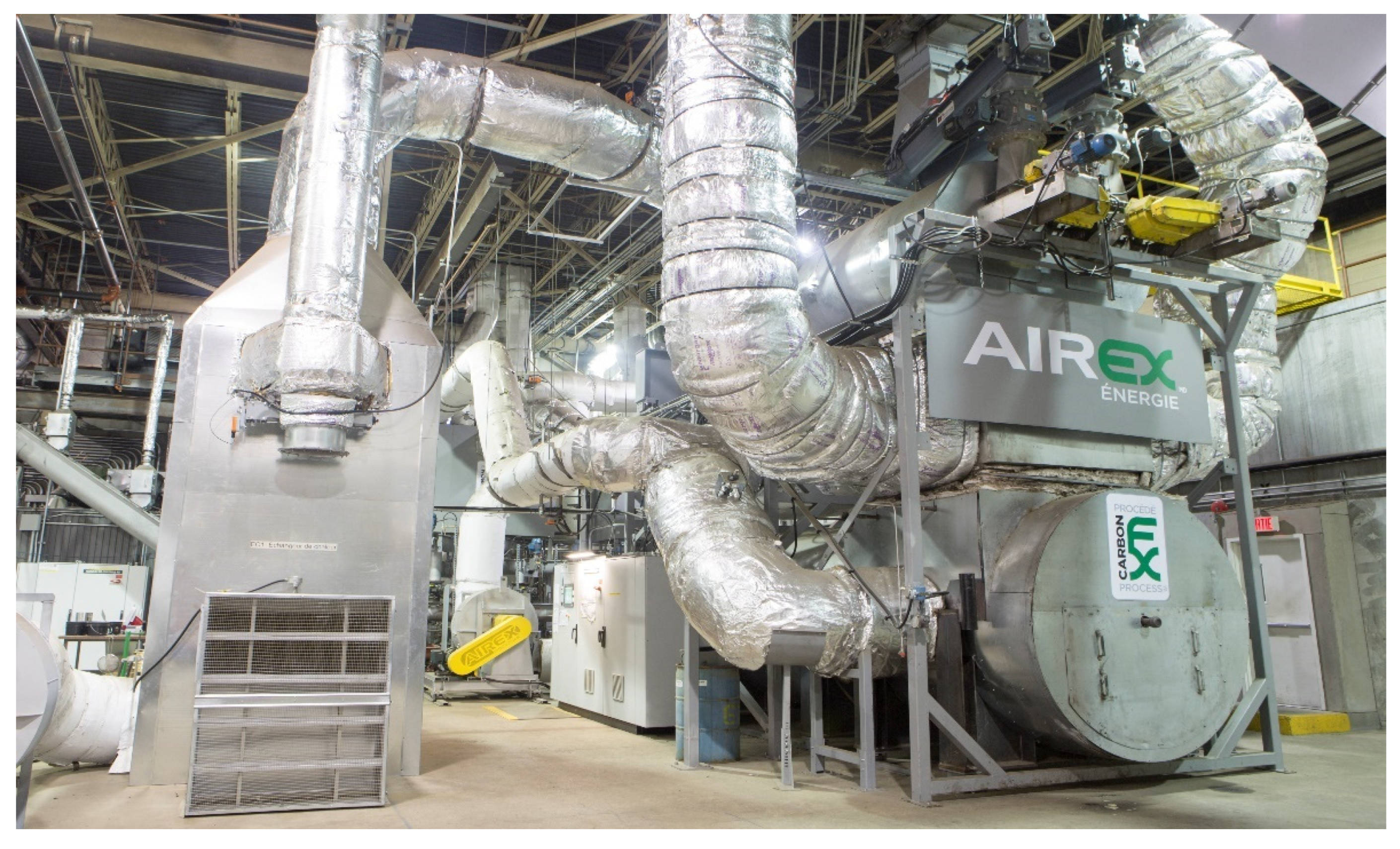
- Energy, A. Industrial Applications Of Solid Biofuels—Carbonfx Technology-Airex Energy. CCRA. 2012. Available online: http://www.cancarb.ca/pdfs/pubs/Airex%20CCRA%20-%20Torrefaction%20Bertrand.pdf (accessed on 5 February 2022).
- Torrefaction and Pelleting. Available online: https://pellets-wood.com/torrefaction-and-pelleting-o93.html (accessed on 5 February 2022).
- Adrian, Ł.; Szufa, S.; Piersa, P.; Kuryło, P.; Mikołajczyk, F.; Kurowski, K.; Pochwała, S.; Obraniak, A.; Stelmach, J.; Wielgosiński, G.; et al. Analysis and Evaluation of Heat Pipe Efficiency to Reduce Low Emission with the Use of Working Agents R134A, R404A and R407C, R410A. Energies 2021, 14, 1926. [Google Scholar] [CrossRef]
- Topell Energy. From Torbed Reactor System 2009. Available online: www.topellenergy.com/technology/torbed-reactor-system/ (accessed on 8 January 2022).
- McDonough, J.R.; Law, R.; Reay, D.A.; Groszek, D.; Zivkovic, V. Miniaturisation of the toroidal fluidisation concept using 3D printing. Chem. Eng. Res. Des. 2020, 160, 129–140. [Google Scholar] [CrossRef]
- Koppejan, J.; Sokhansanj, S.; Melin, S.; Madrali, S. Status Overview of Torrefaction Technologies, A Review of the Commercialization Status of Biomass Torrefaction. 2012. Available online: https://www.ieabioenergy.com/wp-content/uploads/2015/11/IEA_Bioenergy_T32_Torrefaction_update_2015b.pdf (accessed on 5 February 2022).
- Blissett, R.; Sommerville, R.; Rowson, N.; Jones, J.; Laughlin, B. Valorisation of rice husks using a TORBED® combustion process. Fuel Process. Technol. 2017, 159, 247–255. [Google Scholar] [CrossRef] [Green Version]
- Schmidt, L. A Comprehensive Analysis of Torrefaction Technologies for Producing Advanced Wood Pellets; Report Produced for the Council of Western State Foresters; FutureMetrics: Bethel, ME, USA, 2021. [Google Scholar]
- BTL Dryers. Available online: https://www.pawlica.eu/products/industrial-dryers/belt-dryers/bioplant-residues/btl.html (accessed on 8 January 2022).
- Beltomatic Continuous Belt Dryer. Available online: http://www.biogreen-energy.com/beltomatic-belt-dryer (accessed on 1 February 2022).
- Martin, D.; Halina, P.; Michal, C.; Brzdekiewicz Artur, S.Z. Technologies for the Production of Biochar—Advantages and Disadvantages. ICIMB Inst. Ceram. i Mater. Bud. Build. Mater. 2015, 21, 7–21. [Google Scholar]
- Microwave Torrefaction of Biomass. 2011. Available online: https://patentimages.storage.googleapis.com/c0/12/08/a0248e1f2bbdcc/US20110219679A1.pdf (accessed on 5 February 2022).
- Osman, M.S.; Kong, S.; Law, M.C. Numerical Simulation and Experimental Validation of Microwave Torrefaction for Empty Fruit Bunches Pellet; E-Bangi: Bangi, Malaysia, 2019; p. 16. [Google Scholar]
- Hartig, J.; Howard, H.C.; Stelmach, T.J.; Weimer, A.W. DEM modeling of fine powder convection in a continuous vibrating bed reactor. Powder Technol. 2021, 386, 209–220. [Google Scholar] [CrossRef]
- Soponpongpipat, N.; Nanetoe, S.; Comsawang, P. Thermal degradation of cassava rhizome in thermosyphon-fixed bed torrefaction reactor. Processes 2020, 8, 267. [Google Scholar] [CrossRef] [Green Version]
- Shaking Fluid Bed Dryer versus Vibrating Fluid Bed Dryer. Available online: https://temaprocess.com/vibrating-fluid-bed-dryer/ (accessed on 12 January 2022).
- Dhungana, A.; Basu, P.; Dutta, A. Effects of Reactor Design on the Torrefaction of Biomass. J. Energy Resour. Technol. 2012, 134, 041801. [Google Scholar] [CrossRef]
- Crnogaca, B. Torrefaction as a process for biomass conversion into biocoal. Tehnika 2017, 72, 323–327. [Google Scholar] [CrossRef] [Green Version]
- Wang, M.J.; Huang, Y.F.; Chiueh, P.T.; Kuan, W.H.; Lo, S.L. Microwave-induced torrefaction of rice husk and sugarcane residues. Energy 2012, 37, 177–184. [Google Scholar] [CrossRef]
- Pulka, J.; Manczarski, P.; Stępień, P.; Styczyńska, M.; Koziel, J.A.; Białowiec, A. Waste-to-Carbon: Is the Torrefied Sewage Sludge with High Ash Content a Better Fuel or Fertilizer? Materials 2020, 13, 954. [Google Scholar] [CrossRef] [PubMed] [Green Version]
- Kuzmina, J.S.; Director, L.B.; Shevchenko, A.L.; Zaichenko, V.M. Energy efficiency analysis of reactor for torrefaction of biomass with direct heating. J. Physics Conf. Ser. 2016, 774, 012138. [Google Scholar] [CrossRef]


| Pyrolysis | Operating Conditions | Results |
|---|---|---|
| Slow pyrolysis | Temperature: 300–700 °C Vapor residence time: 10–100 min Heating rate: 0.1–1 °C/s Feedstock size: 5–50 mm | Bio-oil: ∼30 wt% Biochar: ∼35 wt% Gases: ∼35 wt% |
| Fast pyrolysis | Temperature: 400–800 °C Vapor residence time: 0.5–5 s Heating rate: 10–200 °C/s Feedstock size: <3 mm | Bio-oil: ∼50 wt% Biochar: ∼20 wt% Gases: ∼30 wt% |
| Flash pyrolysis | Temperature: 800–1000 °C Vapor residence time: <0.5 s Heating rate: >1000 °C/s Feedstock size: <0.2 mm | Bio-oil: ∼75 wt% Biochar: ∼12 wt% Gases: ∼13 wt% |
| Raw Biomass Property | Advantages of Torrefaction for Biomass | Refs. |
|---|---|---|
| High moisture content | Decreases the moisture. The hydrogen released increases H2 into syngas at gasification. | [31] |
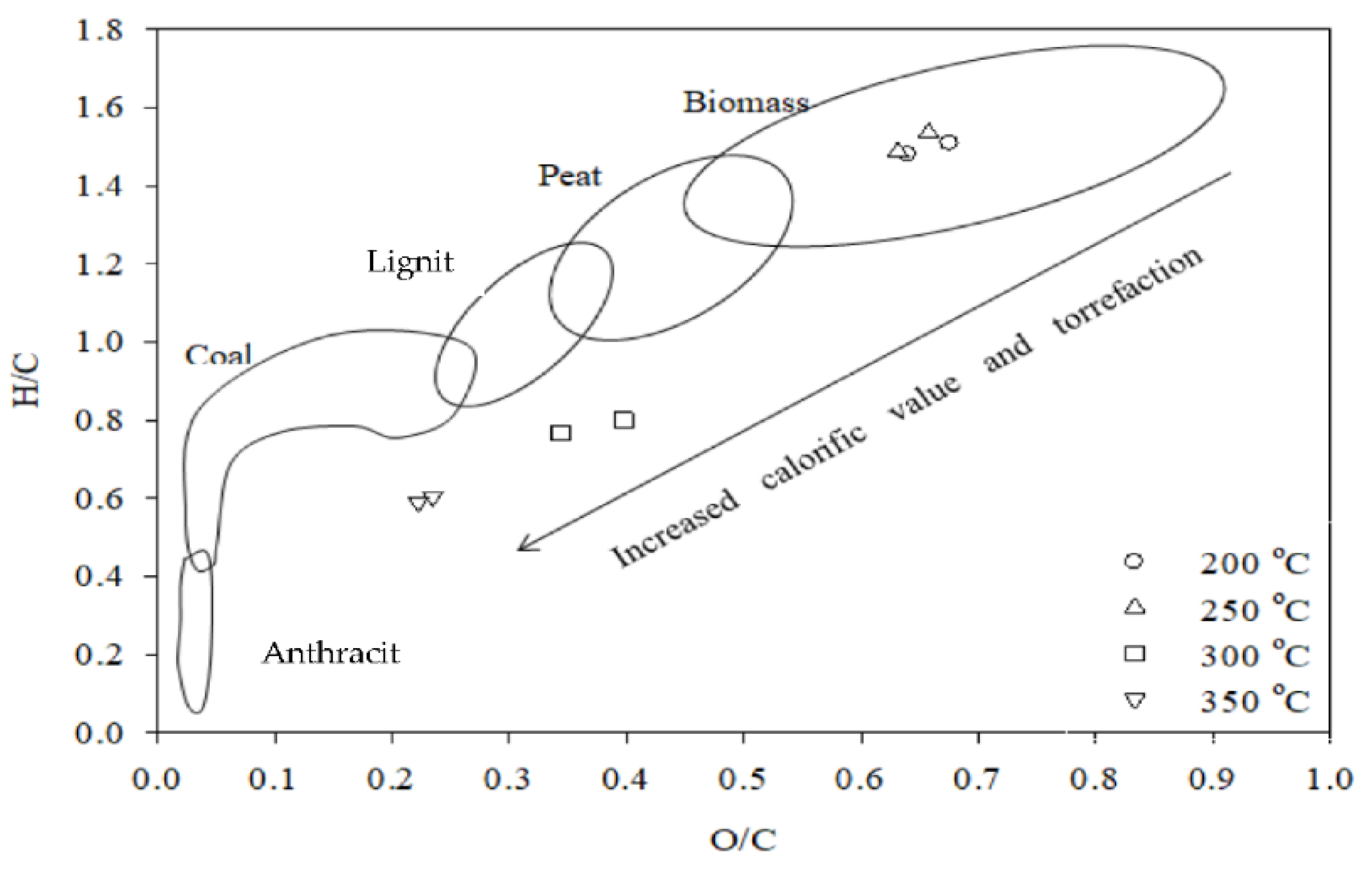
| High H/C and O/C ratio | Leads to higher energy density at biomass (van Krevelen diagram). Deoxygenation and dehydrogenation occur relatively higher than decarbonization, leading to higher carbon density. | [32] |
| High biological degradation | Following torrefaction, significant breakdown of hemicelluloses, widely regarded as a critical nutrient for the development of wood-rotting fungi, leads to an increase in biomass durability. | [33] |
| High hygroscopicity | Increases hydrophobicity. Torrefied biomass has 35% less equilibrium moisture content (EMC), leading to long storage, less moisture, and decomposition risk. | [34] |
| Low calorific value Low mass density | Torrefaction is, therefore, used to remove unwanted components (H and O) from biomass, yielding calorific values similar to coal (25–35 MJ·kg−1). | [35] |
| Poor grindability | Cell walls get destroyed, and pores become the complete result of volatile matter reduction. Torrefaction increases biomass grindability, which is essential for further applications. | [36] |
| Properties of Torrefied Biomass | Dry Torrefaction | Wet Torrefaction | Refs. | |
|---|---|---|---|---|
| Vapor Water | Liquid Water | |||
| Hydrophobic | Yes | Yes | Yes | [42,50] |
| Content of moisture | Lower | Higher | Higher | [51,52] |
| Heating value | Lower | Higher | Higher | [42,50] |
| Bulk density | Low | Low | Low | [53,54] |
| Storage at open atmosphere | Possible | Possible | Possible | [42,50] |
| Purity of the product | Medium | High | High | [42,50] |
| Grindability | High | High | High | [53,54] |
| Product type | Gas, tar, solid | Solid, gas, liquid | Solid, gas, liquid | [42,50] |
| Applications | Fuel and char | Fuel and char | Fuel and char | [51,55,56] |
| Carbon contents | Low | Medium-high | High | [42,50,51] |
| Torrefaction Reactors | |||
|---|---|---|---|
| Direct Heating | Indirect Heating | ||
| Oxygen Free Heating | Low Oxygen Heating | Other | |
| Moving Bed | Augur | Fluidized Bed | Augur |
| Multiple Zones | Moving Bed | Microwave | Rotary Drum |
| Drum | Entrained, Spiral | Hydrothermal | |
| Reactor Type | Medium/Heat Source | Size of Heat Transfer Surface/Reactor Surface | Difficulties in Handling the Process | Movable or Special Elements | Limitation of Scale Up |
|---|---|---|---|---|---|
| Direct Heating Reactor | |||||
| With fixed bed | Flue gas, inert gas, or super-heated steam | Not applicable | Hard | Inert gas heat exchanger or super-heated steam generator; inert gas compressor |
|
| With rotating drum | Exhaust or super-heated steam | Notapplicable | Hard | Drum and drive unit, super-heated steam generator |
|
| With fluidized bed | Solid medium and/or inert gas | Not applicable | Very hard | Gas/air compressor, biomass/carrier solid separator |
|
| With moving bed | Flue gas or Super-heated steam | Not applicable | Hard | Conveyor belt |
|
| Microwave | Microwave | Not applicable | Hard | Microwave generator |
|
| Indirect Heating Reactor | |||||
| Fixed bed | Burning or electrical heater | High | Easy | No moving part |
|
| Screw | Burning or electrical heater | High | Moderate | Screw and its drive set |
|
| With rotating drum | Burning or electrical heater | High | Moderate | Drum and its drive set |
|
| New reactor design (SHS) | Combustion | Small | Easy | No moving part |
|
| Reactor Type | Strength | Weakness |
| Moving-Bed Reactor | Herbaceous and woody biomass residues (rubberwood, agriculture, orchards, and horticulture) [88,89] | The temperature distribution is not uniform, especially for indirect heating |
| Can be employed with both direct and indirect heating | Lack of proper mixing | |
| The reactor is small and relatively basic in structure | Relatively high-pressure drop with small (<5 mm) particles | |
| Accurate temperature control, high heat transfer rate, uniform [90,92] product quality | Longer residence time 30–40 min | |
| No moving parts inside the reactor | Limited biomass size and type acceptable | |
| The capability of processing low-density biomass is high | ||
| Opportunities | Threatens | |
| Flexible when it comes to fueling with a specific fuel and low investment costs | When the reactor reaches scale, it can be dangerous due to the pressure and the possibility of damaging the main body of the reactor | |
| Possible to combine drying and torrefaction [91] | Due to the lack of proper mixing of the biomass, a risk ensues that the carrier will accumulate in the channels | |
| Possible to fill the reactor volume with biomass which leads to a smaller reactor and low cost | Increased risks with larger capacities | |
| Unproven scale-up potential non-uniform products |
| Reactor Type | Strength | Weakness |
| Rotary drum Reactor | Can operate with higher biomass moisture compared to others (sawdust, stalks, switchgrass, wheat straw, and poplar) [98] | The capability of processing low-density biomass is low |
| Proven technology for biomass drying, from 60% to 10% | The mixing of biomass is limited | |
| Uniform heat transfer due to good mixing of sliding bed | Poor control of temperature | |
| Can work in terms of both indirect and direct heating [63] | Lower heat transfer rates (despite good uniformity) | |
| Ability to use a wide range of biomass particle sizes and types | High cost and large space footprint | |
| Due to the friction between drum wall and biomass, the output dust increases | ||
| Limited upscaling ability because the area of heat transfer to biomass during carbonization is limited | ||
| Maximum capacity is reached at 10–12 t/h input or t/h torrefied product [93] | ||
| Opportunities | Threatens | |
| Less gas emission, cleaner environment | Risk of use | |
| Relatively proven technology with other applications such as biomass drying and pyrolysis | To support the solid tumbling motion, the maximum fill volume of the reactor is limited to about 30%. |
| Reactor Type | Strength | Weakness |
| Torbed Reactor | Good torrefaction results on woody biomass; forestry residue, rice husks, straw | Only fine wood particles, sensitive to changes in the size |
| Horizontal motion on the bed causes high impact gas velocities and thus higher heat and mass transfer rates, and provides higher efficiency and lower reaction time [82] | Less control of residence time for each particle [99] | |
| Accepts high water content biomass feeds | Flue gas dilution by the fluidization process | |
| Very rapid start-up, simple to operate and automate, 90 s–5 min residence time | ||
| No sand bed | ||
| Low-pressure drop compared to the others | ||
| Opportunities | Threatens | |
| Consistent product, low carbon ashes (at combustion) | Risk of carbonization due to high temperatures | |
| Torbed reactor technology is considered a proven technology for various applications, including combustion | High heat transfer and high temperature make the process sensitive to variation in particle size (smaller particles could potentially lose much more volatiles compared to bigger ones) | |
| The installations have the lowest footprint of any similar technology. This leads to comparatively inexpensive capital investment for a given output capacity [85] | Formation of fine particles due to internal abrasion in the bed (risk of explosion in later stages) | |
| Available for process gas circulation, which leads to less energy consumption | ||
| Scalable technology (up to 25 t/h) |
| Developer | Technology | Capacity (ton/y) | Country | Scale and Status |
|---|---|---|---|---|
| Agri-Tech Producers LLC | Belt Reactor | 13,000 | Columbia, South Carolina | Pilot stage, operational |
| APS Ekoinnowacje | Counter-flow reactor | 360 | Lodz, Poland | Semi-Pilot, operational |
| Airex | Cyclonic Bed | 3000 | Canada | Planning 10,000–30,000 ton/y with SUEZ partnership, available |
| Bio Energy Development North AB | Dedicated screw reactor | 16,000 | Sweden | Demonstration scale, available |
| New Earth Renewable Energy Fuels, Inc. | Fixed Bed | Unknown | Unknown | Out of business |
| Bioenergy Development & Production | Fluidized Bed | Unknown | Nova Scotia, (CAN) | Pilot, unknown |
| Rotawave, Ltd. | Microwave | 120,000 | Chester (UK) | Stopped in BC, Partnership with Maine, unknown |
| ECN–Andritz | Moving Bed | 10,000 | Stenderup (DK) | Combine technology with Andritz |
| Thermya/Grupo Lantec | Moving Bed | 20,000 | Urnieta (SP) | Early-stage commissioning |
| Thermya/LMK Energy | Moving Bed | 20,000 | Mazingarbe (Fr) | Early-stage commissioning |
| Torrec | Moving Bed | 10,000 | Mikkeli (FI) | Demonstration scale, available |
| Grupo Lantec | Moving Bed | 20,000 | Urnieta (SP) | Demonstration scale, unknown |
| Integro Earth Fuels, LLC | Multiple Hearth | 11,000 | Greenville (USA) | Demonstration scale, unknown |
| Wyssmont | Multiple Hearth | Unknown | USA | Unknown |
| CMI NESA | Multiple Hearth | Unknown | Seraing (BE) | Unknown |
| Clean electricity generation | Oscillating bed | 30,000 | UK | Commercial scale, available |
| Horizon Bioenergy | Oscillating belt convenyor | 45,000 | Steenwijk (NL) | Dismantled after plant fire at 2012 |
| Atmosclear SA | Rotary Drum | 50,000 | Latvia, New Zealand, USA | Out of business |
| Earth Care Products | Rotary Drum | 20,000 | Kansas (USA) | Demonstration scale, available |
| EBES AG | Rotary Drum | 10,000 | Frohnleiten (AU) | 1 mt/h pilot plan in commissioning |
| Renergy/4Energy Invest | Rotary Drum | 38,000 | Amel (BE), Ham (Be) | Project terminated |
| Renergy/4Energy Invest | Rotary Drum | 38,000 | Ham (Be) | Project terminated |
| Torr-Coal B.V. | Rotary Drum | 35,000 | Dilsen-Stokkem (BE) | Commercial scale, available |
| Andritz | Rotary Drum | 10,000 | Frohnleiten (AT) | Demonstration scale, out of business |
| BioLake B.V. | Screw Convenyor | 5000–1000 | Eastern Europe | Pilot stage |
| FoxCoal B.V. | Screw Convenyor | Unknown | Winschotel (NL) | Pilot, now bankrupt |
| Solvay / New Biomass Energy | Screw Reactor | 80,000 | (FR), Missisippi (USA) | Commercial scale, available |
| Arigma Fuels | Screw Reactor | 20,000 | Ireland | Commercial scale, available |
| Topell Energy | Torbed, Fluidized bed | 60,000 | Duiven (NL) | Commercial scale, available |
| Airless Systems | Unknown | 40,000 | Latvia | Out of business |
| HM3 Energy | Unknown | Unknown | Oregan, US | Pilot Demo plant |
| River Basin energy | Unknown | Unknown | Laramie, Wyoming (USA) | Pilot stage |
| Torrefaction Systems Inc. | Unknown | Unknown | Unknown | Pilot |
| WPAC | Unknown | 35,000 | Unknown | Unknown |
Publisher’s Note: MDPI stays neutral with regard to jurisdictional claims in published maps and institutional affiliations. |
© 2022 by the authors. Licensee MDPI, Basel, Switzerland. This article is an open access article distributed under the terms and conditions of the Creative Commons Attribution (CC BY) license (https://creativecommons.org/licenses/by/4.0/).
Share and Cite
Piersa, P.; Unyay, H.; Szufa, S.; Lewandowska, W.; Modrzewski, R.; Ślężak, R.; Ledakowicz, S. An Extensive Review and Comparison of Modern Biomass Torrefaction Reactors vs. Biomass Pyrolysis—Part 1. Energies 2022, 15, 2227. https://doi.org/10.3390/en15062227
Piersa P, Unyay H, Szufa S, Lewandowska W, Modrzewski R, Ślężak R, Ledakowicz S. An Extensive Review and Comparison of Modern Biomass Torrefaction Reactors vs. Biomass Pyrolysis—Part 1. Energies. 2022; 15(6):2227. https://doi.org/10.3390/en15062227
Chicago/Turabian StylePiersa, Piotr, Hilal Unyay, Szymon Szufa, Wiktoria Lewandowska, Remigiusz Modrzewski, Radosław Ślężak, and Stanisław Ledakowicz. 2022. "An Extensive Review and Comparison of Modern Biomass Torrefaction Reactors vs. Biomass Pyrolysis—Part 1" Energies 15, no. 6: 2227. https://doi.org/10.3390/en15062227
APA StylePiersa, P., Unyay, H., Szufa, S., Lewandowska, W., Modrzewski, R., Ślężak, R., & Ledakowicz, S. (2022). An Extensive Review and Comparison of Modern Biomass Torrefaction Reactors vs. Biomass Pyrolysis—Part 1. Energies, 15(6), 2227. https://doi.org/10.3390/en15062227