Abstract
In this research, the shuttle effect and the low sulfur activation of lithium–sulfur batteries were mitigated by coating the cathode side of Celgard 2400 separators with mixtures of carbon black/chitosan or carbon black/polyvinylidene fluoride using the simple slurry technique. Carbon nanoparticles and the polar groups of the polymers were responsible for boosting the reaction kinetics of sulfur and the chemical and physical trapping of lithium polysulfides. The adsorption of sulfur species in the coated separators was confirmed by the morphologic changes observed in the AFM and SEM images and by the new elements presented in the EDX spectra after 100 charge/discharge cycles. The high intensity of the peaks in the cyclic voltammograms and the long plateaus in the discharge profiles support the improvement in the reaction kinetics. The batteries with the carbon black/chitosan- and carbon black/polyvinylidene fluoride-coated separators reached high specific discharge capacities of 833 and 698 mAhg−1, respectively, after 100 cycles at 0.5 C. This is promising for this kind of technology, and detailed results are presented in the article.
1. Introduction
The generation of energy from fossil fuels is one of the main causes of pollution, which is currently affecting the planet. It is estimated that, by 2100, carbon dioxide (CO2) emissions will cause global warming, which will cause an increase in the average temperature between 4 and 6 °C [1]. In addition, the depletion of fossil fuels has been identified as a future challenge, as it is estimated that oil reserves will run out in the next 40 years, while coal and natural gas will last a maximum of another 150 years [2]. Due to the abovementioned reasons, the research and development of new and better sources of clean energy has become a global priority.
Batteries have positioned themselves as the most important energy accumulators. Since their inception, they have been constantly developed upon to improve their electrochemical properties in order to meet the growing technological needs of society. In the last 25 years, lithium-ion (Li-ion) batteries have played a crucial role in the development of energy storage technologies, currently being the most used batteries in rechargeable portable electronic devices [3].
The search for new alternatives has been necessary to meet the requirements of different applications, and it has led to taking back the concept of lithium–sulfur (Li-S) batteries. The resurgence of this idea is due to the lightness, abundance, low cost, low toxicity, and high energy density of sulfur. Moreover, it is also due to the high theoretical specific capacities of both elements, 3860 mAh g−1 for Li and 1675 mAh g−1 for S. Nevertheless, the high electrical resistance, the fading of the capacity, and the self-discharge of the cell are the main disadvantages that they present [4,5]. In addition, these kinds of systems present a typical 80% volume expansion due to the dissolution–precipitation of polysulfides in comparison with solid S8(s) [6].
The previously mentioned disadvantages are mainly caused by the dissolution of medium-/long-chain lithium polysulfides in ether electrolyte and the subsequent migration of the cathode toward the anode to react with this last electrode. This process is known as the “shuttle effect”, and it results in poor coulombic efficiency (CE, relationship between the discharge and charge of the battery), low active material activation, rapid capacity fade, and short cycle longevity [7,8].
Some efforts to prevent the dissolving of cathode lithium polysulfides in electrolytes have been cited in the literature. For example, modifications of the cathode have been made with host materials that house the S, such as carbon arrangements, inorganic compounds, and polymers, and even by adding protective layers [8]. According to Eftekhari and Kim, an ideal cathodic material must have characteristics such as a base material made of a conductive carbon, with rough mesoporosities that confine and trap both S and polysulfides. Cathode materials must incorporate redox mediators, be doped with selenium, and be covered by a protective polymer layer [9]. However, generating cathodes with the above characteristics would be expensive. Therefore, the large scale use of these electrodes may not be economically profitable. Despite the cost, generating cathodes with the above characteristics is not the definitive solution for the “shuttle effect”. Since liquid electrolytes must be in contact with S and confining structures to use the total capacity of the cell, this implies that polysulfides will always be exposed, and they tend to solubilize in electrolytes to diffuse to the anode [10]. Likewise, a complete blockade of the dissolution of these species cannot be achieved because this process is thermodynamically favorable [11].
Another alternative approach to suppress the “shuttle effect” is controlling the composition of electrolytes. Researchers have shown that certain electrolytes can prevent the dissolution of polysulfides and, consequently, their diffusion. The problem associated with this approach is that the ionic conductivity and chemical stability of electrolytes vary, which can lead to safety and performance problems in the battery [12].
Regarding the strategies taken to mitigate the “shuttle effect” from the anode, the formation of protective layers on the surface of the electrode is found. However, this means giving up the advantages of high charge/discharge speed and the high energy density of Li-S batteries. Another strategy is the replacement of Li by another element, and the most used element after Li is silicon (Si), because it has the second highest theoretical capacity. However, by replacing Li with Si, the values of the electrical properties of these batteries also reduce [13].
The performance of the cell is influenced by the modifications of all its components, be it the electrodes, the electrolyte, or the separator [5]. Separators have been modified with different materials to help the cathode avoid diffusions and keep these species on the side of this electrode in order to reduce or eliminate the disadvantages of these types of batteries. Different investigations have been able to determine that polar materials, atoms, and electron donor groups form chemical bonds with lithium polysulfides, thus reducing their dissolution and diffusion processes [8,9]. In addition, it has been proven that inorganic compounds and carbon structures can inhibit the migration of polysulfides by physical blockages. Moreover, these materials can improve electrical conduction in the cathode zone, resulting in high sulfur activation [8].
Modifying separators with polymers that contain polar groups, such as amines, amides, esters, and alcohols, is a simple and efficient strategy that can overcome many issues related to Li-S batteries. Diverse studies have demonstrated that polymers with polar functional groups, such as carboxylic acid of poly (acrylic acid), can prevent the “shuttle effect” through the Li bonds formed between polar functional groups and polysulfides [14]. Furthermore, carbonaceous materials physically block the diffusion of lithium polysulfides and facilitate the movement of electrons. Zhang reported initial discharge capacities up to 1014.5 mAh g−1 when a thin layer of a combination of reduced graphene oxide and carbon black was deposited over the separator [15].
In this article, Celgard 2400 separators were coated on the cathode side with carbon black/chitosan or carbon black/polyvinylidene fluoride mixes, which contain abundant and low-cost materials. Moreover, the coatings were deposited using the cheap and simple slurry technique. In these coatings, polymers work as a chemical and physical barrier against the diffusion of lithium polysulfides through the separator. Carbon nanoparticles act as a physical barrier and increase the flow of electrons in the cathode zone, and, therefore, more sulfur activation occurs. The electrochemical properties of the Li-S batteries were enhanced, especially their specific capacity.
2. Materials and Methods
2.1. Preparation of C/PVDF- and C/CTS-Modified Separators
Commercial separator Celgard 2400 was put into plasma generator chamber Harrick Plasma Cleaner PDC-32G, air gas was introduced into the chamber with a controlled pressure ≤ 0.2 Torr, and a radiofrequency wave with a power of 18 W was used for 20 s.
C/PVDF and C/CTS coatings were fabricated using the slurry-coating method. They were prepared by being mixed in a planetary ball mill (Retsch PM 100) for 1 h at 500 rpm, using 60 wt% Super P conductive carbon and 40 wt% polyvinylidene fluoride (PVDF) or chitosan (CTS). As solvents, N-metil-2-pirrolidona (NMP) was used for the C/PVDF mix, and acetic acid (HAc) 0.1 mol∙L−1 was used for the C/CTS mix. Once the cathode side of the separators received the plasma treatment and the coatings, they were left to dry for 24 h at room temperature. The sulfur mass loading in the cathodes was approximately 1.3 mg cm−2.
2.2. Cell Assembly
The sulfur cathode was also fabricated using the slurry-coating method. Using NMP as a solvent, 55 wt% sulfur, 40 wt% Super P conductive carbon, and 5 wt% PVDF were mixed in a mortar agata. The slurry was coated on an aluminum foil and left to dry for 24 h at room temperature. The pure lithium foil was used as the anode. Pristine PP, coated C/PVDF, or coated C/CTS separators were used as separator between the cathode and anode. The electrolyte concentration was 1 mol∙L−1 of lithium bis (trifluoromethanesulfonyl)imide (LiTFSI) in 1,3-dioxolane (DOL) and 1,2-dimetoxyehtane (DME) solution (1:1 by volume). The volume of the electrolyte in each cell was about 150 μL.
2.3. Characterization
Functionalization of the cathode side surface of the separators was studied by Fourier transform infrared spectrometer (model: Nicolet 380, Thermo Scientific, Waltham, MA, USA) and contact angle measurements by Goniometer/Tensiometer (ram-hart Model 590 Advanced Automated). Morphology of the samples was observed using a scanning electron microscope (SEM, JEOL JSM-7500F, Boston, CA, USA) and an atomic force microscope (Park System NX10, Suwon, Korea). Energy-dispersive X-ray spectroscopy (EDX, JEOL JSM-7500F, Boston, CA, USA) was used in order to identify elements on the surface of the separators. Electrolyte uptake (%EU) was measured as follows:
where WB and WA are the weight of the separator before and after absorbing the electrolyte for 4.5 h, respectively.
2.4. Electrochemical Measurements
Cyclic voltammetry (CV) measurements were performed on electrochemical workstations (Gamry Reference 3000 and Autolab PGSTAT101), where the voltage window was 1.8–2.8 V and the scanning rate was 0.2 mVs−1 [16,17]. Galvanostatic charge and discharge tests were carried out on battery test instruments (Gamry Reference 3000 and Autolab PGSTAT101) in a voltage range of 1.8–2.8 V (vs. Li/Li+) and with a constant current density of 0.5C.
3. Results and Discussion
Before being coated, the Celgard 2400 separators were treated with air plasma to functionalize their cathode side and to obtain a more polar surface. To verify the functionalization, the separators were analyzed by Fourier transform infrared spectroscopy (FT-IR) before and after plasma treatment. Figure 1a shows the spectra of the Celgard separators before and after plasma treatment. Before this process, it was noted that the FT-IR spectra of the Celgard 2400 separators had four peaks between 2750 and 3000 cm−1. The peaks at 2950 and 2868 cm−1 correspond to the asymmetric and symmetric stretching vibrations of CH3 groups, respectively. The peaks at 2915 and 2837 cm−1 are attributed to the asymmetric and symmetric stretching vibrations of CH2 groups, respectively. The signal at 1455 cm−1 is caused by the asymmetric deformation vibrations of CH3 groups or by the scissor vibrations of CH2 groups [18]. The maximum signal displayed at 1374 cm−1 is due to the symmetric deformation vibrations of CH3 groups [19]. Between 1250 and 750 cm−1, there are six peaks. The peak at 1166 cm−1 represents the asymmetric stretching of C-C bond and the vibrations of the C-H bonds. The peak at 994 cm−1 is due to the oscillating asymmetric vibrations of CH3 groups. The peak at 970 cm−1 is attributed to the asymmetric oscillations of CH3 and to the asymmetric stretching vibrations of the C-C bond. At 901 cm−1, a signal is identified that represents the symmetric and asymmetric vibrations of the C-C bond and the asymmetric movement of CH3. The oscillating vibrations of CH2 groups can be identified by the peaks at 840 and 809 cm−1 [18].
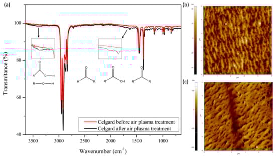
Figure 1.
(a) FT−IR spectra of Celgard separator before and after air plasma treatment, and AFM images of the separator before (b) and after (c) plasma treatment.
All the above signals are present in the infrared spectrum of the separator treated with air plasma. Nevertheless, the separator’s infrared spectrum shows peaks at 1724 and 1629 cm−1. These signals indicate the existence of different types of double C and O bonds, such as those with aldehydes, ketones, and carboxylic acids [19]. Additionally, in the region between 3500 and 3250 cm−1, it can be observed that there is a slight curve, which represents the characteristic peak of the vibration of the C-O bond present in alcohols and carboxylic acids [20].
As we can see in the AFM images, when the separator is treated with air plasma, its morphology changes. Before plasma treatment (Figure 1b), it can be observed that there is a straight microstructure with slit-like-shaped pores, where each pore is trapped by nanofibers with a uniaxial orientation due to the stretching of the material in the manufacturing process [21,22]. In Figure 1c, it can be observed that, after plasma treatment, the initial arrangement is replaced with big globular aggregates on or in place of the fibers [23,24,25]. The above phenomenon is due to the etching process generated by the reaction of carbon atoms on the surface of the separator with the ionized atoms of oxygen of the plasma state. As a result of this process, new functional groups are formed on the surface of the separator, as well as volatile products with a low molecular weight [19,24,26].
The contact angle measurements complement the FT-IR results and confirm the functionalization of the separator. As presented in Table 1, before plasma treatment, the separator has a greater value than the separator with plasma treatment, and this reduction in contact angle is due to the presence of polar groups, mainly oxygen, on the separator surface. Furthermore, these polar groups increase the separator’s surface energy; therefore, it has greater humidification, and due to this effect, coating adhesion may be enhanced.

Table 1.
Contact angle measurements of Celgard 2400 before and after air plasma treatment.
As observed in Figure 2, there are no fractures or cracks in the nanocarbon/polymer structures of the C/PVDF and C/CTS coatings, and the lack of these defects confirms the good adhesion between the functionalized separators and the coatings. Both separators, that is, C/PVDF and C/CTS, have homogeneously distributed coatings and a porous layer of carbon nanoparticles with a size of approximately 0.1 μm, and they are interconnected due to the PVDF or CTS polymers, respectively. Moreover, the coatings of both modified separators have a minor pore size compared with the pores of the pristine separators; this implies that lithium polysulfides should be physically trapped in these coatings, without affecting the movement of Li+ ions [27]. The similitude of the features among both coatings is mainly due to the carbon nanoparticles and the fact that both coatings were synthesized with the same methodology. Nevertheless, both coatings have different behaviors because their polymers have different chemical structures and polar groups. Moreover, different research groups have demonstrated the good adhesion of the coatings through cross-sectional SEM images [28,29].

Figure 2.
SEM, AFM images, and EDX spectra of C/PVDF separator (a–c) and C/CTS separator (d–f).
After 100 charge/discharge cycles, the size of the carbon nanoparticles in the C/PVDF separator increased approximately from 0.1 μm to 0.5 μm, and there was deposited material in the interspaces of this coating (Figure 3a,b). These changes suggest the deposition of electrolyte salt and the physical trapping of lithium polysulfides and active material on the carbon/polymer structure [30,31]. Moreover, the C/PVDF coating had no cracks or fractures after the extensive fatigue process that the cell underwent during the 100 charge/discharge cycles, which is an indication that it was able to withstand the expansion and contraction processes of the cathode [32].
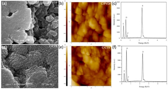
Figure 3.
SEM, AFM images, and EDX spectra of C/PVDF separator (a–c) and C/CTS separator (d–f) after 100 charge/discharge cycles.
In Figure 3d,e, the separator with the C/CTS coating shows neither cracks nor fractures, but it has bigger particles deposited in the interspaces of the carbon/polymer structure [32,33]. The increase in particle size is due to electrolyte salt deposition, the physical retention of the active material by the carbon nanoparticles, and chemical retention caused by the lithium bond interactions between the polar groups of chitosan and lithium polysulfides [31,34].
With the elemental analysis of the separators using the EDX technique, the species trapped in the C/PVDF and C/CTS coatings were identified. For the C/PVDF separator before the electrochemical tests (Figure 2c), the signal of C is due to the presence of the carbon nanoparticles and is for the main chain of the polymer. The signal of F is attributed to the polymer substituents, and the signal of O corresponds to the polar groups made by the plasma treatment in the separator. After the electrochemical tests (Figure 3c), the signals of C, O, and F are due to the reasons already explained, but the signals of O and F also correspond to the deposition of the electrolyte salt in the coating [31]. The physical trapping of lithium polysulfides by the carbon nanoparticles is confirmed due to the S signal in Figure 3c.
The elemental analysis of the C/CTS separator is shown in Figure 2f. Before the charge/discharge tests, this separator had the signals of two elements. The signal of C is due to the presence of the carbon nanoparticles and is for the main chain of the polymer. The O signal is because chitosan mainly has polar groups with oxygen. In the EDX spectrum in Figure 3f, after the charge/discharge cycles, two new signals appear. The F signal is for the presence of electrolyte salt in the coating. The S signal is mainly due to the chemical and physical trapping of lithium polysulfides in the coating. The polar groups of chitosan form lithium bonds with polysulfide species, and the carbon nanoparticles absorb them [28,29]. As mentioned above, the presence of the O signal after the electrochemical tests is attributed to the presence of electrolyte salt in the coating.
Electrolyte uptake was determined for the C/CTS, C/PVDF, and pristine separators. As presented in Table 2, this parameter is higher in both modified separators, C/PVDF and C/CTS, because porosities in carbon nanoparticles simultaneously absorb and confine electrolytes [35]. However, the C/CTS separator has the highest value of electrolyte uptake since chitosan has alcohols and amines that form hydrogens bonds with the oxygen atoms of the solvents.
Table 2.
Electrolyte uptake of LiTFSI 1 mol∙L−1 in DME/DOX by the separators.
Cyclic voltammetry was performed for all the batteries evaluated and to study the electrochemical reactions of the Li-S batteries. As presented in Figure 4, all the batteries evaluated have two anodic and cathodic peaks that correspond to the oxidation and reduction process of sulfur, respectively. The R peak suggests the formation of long-chain lithium polysulfides (Li2Sx, 4 ≤ x ≤ 8), while the R’ peak indicates the reduction of these long-chain polysulfides to short-chain polysulfides (Li2Sx, 1 < x ≤ 4). The O’ peak is associated with the oxidation of Li2S to short-chain lithium polysulfides and then to long-chain polysulfides, while the O peak indicates the oxidation of long-chain lithium polysulfides to sulfur, S [36].
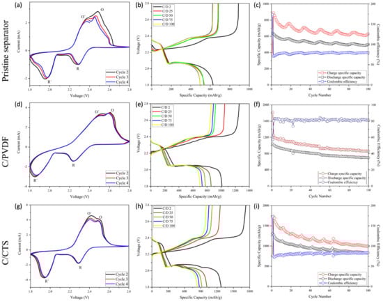
Figure 4.
Cyclic voltammograms, charge/discharge profiles, and cycling performance of battery with pristine separator (a–c), battery with C/PVDF separator (d–f), and battery with C/CTS separator (g–i).
When comparing the cyclic voltammograms, it is noted that the C/PVDF and C/CTS batteries have an overlap of the running cycles, both in the oxidation and reduction peaks. The above information suggests adequate cyclical stability of these formulated batteries. Furthermore, these two batteries have a higher current intensity at the anodic and cathodic peaks, indicating a greater increase in the conductivity of the cathode material due to the carbon nanoparticles of the C/PVDF and C/CTS coatings. Moreover, H. Wei and coworkers used an approach in which electrochemical impedance spectroscopy (EIS) showed that a coated separator had lower charge transfer resistance than that of a pristine separator, thus improving the conductivity [37]. The cathodic R’ peak in the pristine battery has a lower intensity than that of the others, which demonstrates no polysulfide blocking and conversion. However, the high intensity of the O and O´ anodic peaks for the batteries with the modified separators suggests evidence of the excellent blocking of this species and fast polysulfide conversion, which is also suggested by the displacement of the cathodic and anodic peaks [38,39,40].
In the charge/discharge profiles (Figure 4), all of the evaluated batteries have two plateaus in the charge and discharge curves, which agree with the peaks in the voltammograms. The discharging process starts with the reduction of the alpha allotrope form of sulfur S8 to the open-chain S82− (solid-to-liquid change), which corresponds to the first plateau. The following decrease in the graphs is associated with the liquid–liquid conversion from S2−8 to S−4. The final plateau depicts the conversion of soluble S42− polysulfides to the solid species Li2S2, and the final decrease indicates the solid–solid conversion from Li2S2 to Li2S [5,41,42]. The final inflexion point shown at the end of the second plateau of the discharge process in the battery with the C/CTS separator suggests the complete transformation of lithium polysulfides to the final product Li2S and, as such, demonstrates high specific capacity because of the high sulfur utilization. For the battery with the C/PVDF separator, a little inflexion is also observed, but in the discharge profile of the pristine battery, evidence of this process does not appear; this indicates an incomplete transformation of polysulfides to Li2S, which generates low sulfur utilization [43].
In Figure 4b, the battery with the pristine separator has the shortest plateaus and the lowest values of discharge specific capacity; this indicates low sulfur activation, lithium polysulfide diffusion through the battery, and the loss of active material. However, the modified separators with the C/PVDF and C/CTS coatings have the highest values of discharge specific capacity, as shown in Figure 4e,h. These modified batteries possess the highest and longest second discharge plateaus and low polarization in comparison with the simple battery, signifying faster redox reaction kinetics for sulfur [44]. It is believed that the mentioned results are due to the carbon nanoparticles deposited on the separator, which raise the conductivity in the cathode zone and provide a wider conductive surface, thus increasing sulfur activation [28]. The battery with the C/CTS separator has the highest values of discharge specific capacity due to the fact that chitosan has alcohols and amines that can chemically trap lithium polysulfide. The chemical trapping of lithium polysulfides restrains the shuttle effect in Li-S cells to a greater degree and ensures the subsequent utilization of elemental sulfur for battery cyclic stability [14,27]. The initial discharge specific capacities obtained were 1308 mAh g−1 for C/CTS, 1080 mAh g−1 for C/PVDF, and 639 mAh g−1 for the standard battery. Zhen L. et al. and Deng C. and coworkers proved that the introduction of functional groups and barriers on the surface of separators mitigates the diffusion of polysulfides, while pristine separators could not achieve this [27,45]. Therefore, it is suggested that there is free diffusion of lithium polysulfides when a pristine separator is used and blocking behavior when a coated separator is used.
As presented in the cycle performance of the batteries (Figure 4c,f,i), after 100 charge/discharge cycles, coulombic efficiency is higher in the batteries with modified separators, that is, C/CTS (84%) and C/PVDF (81%), than in the standard battery (79%). The enhancement in coulombic efficiency is mainly due to the mitigation of lithium polysulfide diffusion caused by physical and chemical trapping. This leads to higher efficiency in reaction kinetics and enhances the reversibility of the redox system [46,47]. However, as can be observed, the cycling performance in the modified batteries is lower than in the battery with the pristine separator. After 100 charge/discharge cycles, capacity fell from 1309 to 883 mAh g−1 in the C/CTS battery (0.64% retention per cycle), from 1040 to 698 mAh g−1 in the C/PVDF battery (0.67% retention per cycle), and from 639 to 500 mAh g−1 in the standard battery (0.78% retention per cycle). We speculate that this drop in cell capacity is because of the high formation of lithium polysulfide due to the high activation of sulfur that had the modified batteries. In the case of the C/CTS battery, if lithium bonds have a binding energy of more than > 2eV, they could dissociate lithium polysulfide bonds in Li+ and Sx2− (2 ≤ x ≤ 8), so this reduces the quantity of active sulfur, and, hence, the capacity retention decays [48,49,50,51]. Even though the modified batteries have less capacity retention than the standard battery, they still have bigger specific capacities in their last cycle than the standard battery in its first cycle, as seen in Figure 4. It is important to note that the fluctuation presented in the cycling performance graphs is due to the temperature fluctuations throughout the 100 charge/discharge cycles [52], but we believe that this phenomenon could also be the result of the activation/inactivation of sulfur aggregates in the cathode zone.
When comparing the charge/discharge profiles of the three batteries (Figure 5), the formation of a valley at the end of the first discharge plateau and a peak at the beginning of the charging process can be seen in the curves of the standard battery. The presence of the valley is due to the reduction in the viscosity that the electrolyte suffers; this property reaches its maximum value during the first plateau, when the medium-chain lithium polysulfides dissolve. However, when the medium-chain polysulfides are reduced to the insoluble species (Li2S2/Li2S) in the second plateau, the viscosity of the electrolyte is reduced, which is reflected as a valley at the end of the first discharge plateau. The peak at the beginning of the charge curve is attributed to the formation of soluble lithium polysulfides from the insulating layers of insoluble species [53,54,55]. However, for both modified batteries, no peak or valley is observed. For the C/CTS battery, a decrease is shown in the formation of the valley and the peak is absent at the beginning of the charging process. Additionally, because of the peak’s absence at the beginning of the charging process, it is supposed that the coatings reduce the activation barrier needed to oxidize the ionically/electrically insulating nature and non-soluble character of the Li2S species because of the improvement in the electron transfer on the Li2S surface due to the conductive layer of the carbon nanoparticles [56,57,58]. Previous evidence suggests that both coatings can mitigate the diffusion of polysulfides, improve sulfur utilization, and redistribute the insulating active material.
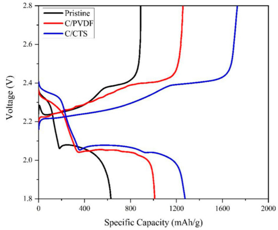
Figure 5.
Comparison of the charge/discharge profiles of cycle 2 for the batteries evaluated.
4. Conclusions
In summary, two novel modified separators with C/CTS and C/PVDF coatings were prepared using the cheap and simple slurry-coating method with materials that enhance the redox reactions of sulfur and utilize chemical and physical strategies to trap lithium polysulfides. An initial plasma treatment was needed for the commercial separator Celgard 2400 with the aim of functionalizing the surface and improving the addition of the mixtures by polar interactions. The morphological alterations of the surface of the coatings, such as changes in the pore size and the agglomeration of materials, after 100 cycles, were due to the presence of lithium polysulfides, which was confirmed by AFM, SEM, and EDX analyses. Additionally, the carbon black layers enhanced electrical conduction and led to a high sulfur activation by speeding up the reaction kinetics of solid to soluble polysulfide species and vice versa. Due to the high sulfur activation, the modified cells with the C/CTS and C/PVDF coatings exhibited impressive initial discharge specific capacities of 1308 and 1080 mAh g−1 at 0.5C, respectively. Even after 100 cycles, the specific capacities (883 and 698 mAh g−1) were higher than the first discharge specific capacity of the standard cell, 639 mAh g−1. This approach should be useful for the design of lithium–sulfur cells that need to deliver outstanding discharge specific capacities in a few cycles. Further research varying the concentration of the components of the coatings or including additives should be performed with the intention to keep a high specific capacity with excellent cyclic stability.
Author Contributions
I.P.-V.: Conceptualization, Methodology, Validation, Investigation, Formal Analysis, Writing—Original Draft, and Visualization. C.C.Z.-G.: Investigation, Resources and Writing—Review and Editing. S.C.-V.: Investigation. A.L.C.: Methodology and Investigation. G.S.-A.: Investigation, Writing—Review and Editing, Visualization, Supervision, and Resources. R.S.K.: Resources and Writing—Review and Editing. J.J.S.-A.: Conceptualization, Methodology, Visualization, Supervision, Writing—Review and Editing, and Resources. All authors have read and agreed to the published version of the manuscript.
Funding
This work was funded by Plan de Mejoramiento Institucional UNA BM-04, Fondos del Sistema del Consejo Nacional de Rectores (FEES-CONARE), Costa Rica; Vicerrectoría de Investigación of the Universidad Nacional, Costa Rica; NSF-EPSCoR Center for the Advancement of Wearable Technologies (CAWT) NSF GRANT NO. OIA-1849243; and NASA PR-SPRInT GRANT NO. 80NSSC19M0236.
Institutional Review Board Statement
Not applicable.
Informed Consent Statement
Not applicable.
Data Availability Statement
Not applicable.
Conflicts of Interest
The authors declare no conflict of interest.
References
- Bruce, P.G.; Freunberger, S.; Hardwick, L.; Tarascon, J.-M. Li–O2 and Li–S batteries with high energy storage. Nat. Mater. 2012, 11, 19–29. [Google Scholar] [CrossRef] [PubMed]
- Höök, M.; Tang, X. Depletion of fossil fuels and anthropogenic climate change—A review. Energy Policy 2013, 52, 797–809. [Google Scholar] [CrossRef] [Green Version]
- Demir-Cakan, R. Li-S Batteries; World Scientific: London, UK, 2017; pp. 1–5. [Google Scholar] [CrossRef]
- Chen, L.; Shaw, L.L. Recent advances in lithium–sulfur batteries. J. Power Sources 2014, 267, 770–783. [Google Scholar] [CrossRef]
- Zhang, X.; Xie, H.; Kim, C.-S.; Zaghib, K.; Mauger, A.; Julien, C. Advances in lithium—Sulfur batteries. Mater. Sci. Eng. R Rep. 2017, 121, 1–29. [Google Scholar] [CrossRef] [Green Version]
- Barai, P.; Mistry, A.; Mukherjee, P.P. Poromechanical effect in the lithium–sulfur battery cathode. Extreme Mech. Lett. 2016, 9, 359–370. [Google Scholar] [CrossRef] [Green Version]
- Reddy, T.B.; Linden, D. Linden’s Handbook of Batteries; McGraw-Hill: New York, NY, USA, 2011; pp. 1.3, 1.6, 1.7, 1.9, 1.10, 1.11, 1.14, A.3, A.12. [Google Scholar]
- Fan, X.; Sun, W.; Meng, F.; Xing, A.; Liu, J. Advanced chemical strategies for lithium–sulfur batteries: A review. Green Energy Environ. 2017, 3, 2–19. [Google Scholar] [CrossRef]
- Eftekhari, A.; Kim, D.-W. Cathode materials for lithium–sulfur batteries: A practical perspective. J. Mater. Chem. A 2017, 5, 17734–17776. [Google Scholar] [CrossRef]
- Park, K.; Cho, J.H.; Jang, J.-H.; Yu, B.-C.; De La Hoz, A.T.; Miller, K.M.; Ellison, C.J.; Goodenough, J.B. Trapping lithium polysulfides of a Li–S battery by forming lithium bonds in a polymer matrix. Energy Environ. Sci. 2015, 8, 2389–2395. [Google Scholar] [CrossRef]
- Shin, E.S.; Kim, K.; Oh, S.H.; Cho, W.I. Polysulfide dissolution control: The common ion effect. Chem. Commun. 2013, 49, 2004–2006. [Google Scholar] [CrossRef]
- Scheers, J.; Fantini, S.; Johansson, P. A review of electrolytes for lithium–sulphur batteries. J. Power Sources 2014, 255, 204–218. [Google Scholar] [CrossRef]
- Rosenman, A.; Markevich, E.; Salitra, G.; Aurbach, D.; Garsuch, A.; Chesneau, F.F. Review on Li-Sulfur Battery Systems: An Integral Perspective. Adv. Energy Mater. 2015, 5, 1500212. [Google Scholar] [CrossRef]
- Song, S.; Shi, L.; Lu, S.; Pang, Y.; Wang, Y.; Zhu, M.; Ding, D.; Ding, S. A new polysulfide blocker–poly(acrylic acid) modified separator for improved performance of lithium-sulfur battery. J. Membr. Sci. 2018, 563, 277–283. [Google Scholar] [CrossRef]
- Zhang, K.; Dai, L.; Xie, L.; Kong, Q.; Su, F.; Liu, Z.; Shi, J.; Liu, Y.; Chen, Z.; Chen, C. Graphene/Carbon Black Co-modified Separator as Polysulfides Trapper for Li-S Batteries. ChemistrySelect 2019, 4, 6026–6034. [Google Scholar] [CrossRef]
- Wei, B.; Shang, C.; Pan, X.; Chen, Z.; Shui, L.; Wang, X.; Zhou, G. Lotus Root-Like Nitrogen-Doped Carbon Nanofiber Structure Assembled with VN Catalysts as a Multifunctional Host for Superior Lithium–Sulfur Batteries. Nanomaterials 2019, 9, 1724. [Google Scholar] [CrossRef] [Green Version]
- He, J.; Chen, Y.; Manthiram, A. MOF-derived Cobalt Sulfide Grown on 3D Graphene Foam as an Efficient Sulfur Host for Long-Life Lithium-Sulfur Batteries. iScience 2018, 4, 36–43. [Google Scholar] [CrossRef] [PubMed]
- Morent, R.; De Geyter, N.; Leys, C.; Gengembre, L.; Payen, E. Comparison between XPS- and FTIR-analysis of plasma-treated polypropylene film surfaces. Surf. Interface Anal. 2008, 40, 597–600. [Google Scholar] [CrossRef]
- Kostov, K.; Nishime, T.; Hein, L.; Toth, A. Study of polypropylene surface modification by air dielectric barrier discharge operated at two different frequencies. Surf. Coat. Technol. 2013, 234, 60–66. [Google Scholar] [CrossRef] [Green Version]
- Jiang, Q.; Li, Z.; Wang, S.; Zhang, H. A separator modified by high efficiency oxygen plasma for lithium ion batteries with superior performance. RSC Adv. 2015, 5, 92995–93001. [Google Scholar] [CrossRef]
- Lee, H.; Yanilmaz, M.; Toprakçi, O.; Fu, K.; Zhang, X. A review of recent developments in membrane separators for rechargeable lithium-ion batteries. Energy Environ. Sci. 2014, 7, 3857–3886. [Google Scholar] [CrossRef]
- Zhang, S.S. A review on the separators of liquid electrolyte Li-ion batteries. J. Power Sources 2007, 164, 351–364. [Google Scholar] [CrossRef]
- Wei, Q. Surface characterization of plasma-treated polypropylene fibers. Mater. Charact. 2004, 52, 231–235. [Google Scholar] [CrossRef]
- Boyd, R.; Kenwright, A.M.; Badyal, J.P.S.; Briggs, D. Atmospheric Nonequilibrium Plasma Treatment of Biaxially Oriented Polypropylene. Macromolecules 1997, 30, 5429–5436. [Google Scholar] [CrossRef]
- Wei, Q.F.; Mather, R.R.; Wang, X.Q.; Fotheringham, A.F. Functional nanostructures generated by plasma-enhanced modification of polypropylene fibre surfaces. J. Mater. Sci. 2005, 40, 5387–5392. [Google Scholar] [CrossRef]
- Altuncu, E.; Üstel, F.; Esen, S.G.; Karayel, E. Influence of Oxygen and Nitrogen Plasma Treatment on Polypropyleme (PP) Bumper Surface. J. Achiev. Mater. Manuf. Eng. 2016, 77, 18–34. [Google Scholar]
- Deng, C.; Wang, Z.; Wang, S.; Yu, J.; Martin, D.J.; Nanjundan, A.K.; Yamauchi, Y. Double-Layered Modified Separators as Shuttle Suppressing Interlayers for Lithium–Sulfur Batteries. ACS Appl. Mater. Interfaces 2019, 11, 541–549. [Google Scholar] [CrossRef] [PubMed]
- Zhang, Z.; Lai, Y.; Zhang, Z.; Li, J. A functional carbon layer-coated separator for high performance lithium sulfur batteries. Solid State Ionics 2015, 278, 166–171. [Google Scholar] [CrossRef]
- Chen, Y.; Liu, N.; Shao, H.; Wang, W.; Gao, M.; Li, C.; Zhang, H.; Wang, A.; Huang, Y. Chitosan as a functional additive for high-performance lithium–sulfur batteries. J. Mater. Chem. A 2015, 3, 15235–15240. [Google Scholar] [CrossRef]
- Tang, H.; Yao, S.; Mi, J.; Wu, X.; Hou, J.; Shen, X. Ketjen Black/Mg0.6Ni0.4O composite coated separator for lithium-sulfur batteries with enhanced electrochemical performance. Mater. Lett. 2017, 186, 127–130. [Google Scholar] [CrossRef]
- Zheng, B.; Yu, L.; Zhao, Y.; Xi, J. Ultralight carbon flakes modified separator as an effective polysulfide barrier for lithium-sulfur batteries. Electrochim. Acta 2019, 295, 910–917. [Google Scholar] [CrossRef]
- Balach, J.; Jaumann, T.; Klose, M.; Oswald, S.; Eckert, J.; Giebeler, L. Functional Mesoporous Carbon-Coated Separator for Long-Life, High-Energy Lithium-Sulfur Batteries. Adv. Funct. Mater. 2015, 25, 5285–5291. [Google Scholar] [CrossRef]
- Guo, Y.; Jiang, A.; Tao, Z.; Yang, Z.; Zeng, Y.; Xiao, J. High-Performance Lithium-Sulfur Batteries with an IPA/AC Modified Separator. Front. Chem. 2018, 6, 222. [Google Scholar] [CrossRef] [PubMed] [Green Version]
- Zu, C.; Su, Y.-S.; Fu, Y.; Manthiram, A. Improved lithium–sulfur cells with a treated carbon paper interlayer. Phys. Chem. Chem. Phys. 2013, 15, 2291–2297. [Google Scholar] [CrossRef] [PubMed]
- Liu, B.; Wang, S.; Wu, X.; Liu, Z.; Gao, Z.; Li, C.; Yang, Q.; Hu, G.-H.; Xiong, C. Carbon nanotube/zirconia composite-coated separator for a high-performance rechargeable lithium–sulfur battery. AIP Adv. 2018, 8, 105315. [Google Scholar] [CrossRef] [Green Version]
- Yin, Y.-X.; Xin, S.; Guo, Y.-G.; Wan, L.-J. Lithium-Sulfur Batteries: Electrochemistry, Materials, and Prospects. Angew. Chem. Int. Ed. 2013, 52, 13186–13200. [Google Scholar] [CrossRef] [PubMed]
- Wei, H.; Ma, J.; Li, B.; Zuo, Y.; Xia, D. Enhanced Cycle Performance of Lithium–Sulfur Batteries Using a Separator Modified with a PVDF-C Layer. ACS Appl. Mater. Interfaces 2014, 6, 20276–20281. [Google Scholar] [CrossRef]
- Azam, S.; Wei, Z.; Wang, R. Cerium oxide nanorods anchored on carbon nanofibers derived from cellulose paper as effective interlayer for lithium sulfur battery. J. Colloid Interface Sci. 2022, 615, 417–431. [Google Scholar] [CrossRef]
- Yao, H.; Yan, K.; Li, W.; Zheng, G.; Kong, D.; Seh, Z.W.; Narasimhan, V.K.; Liang, Z.; Cui, Y. Improved lithium–sulfur batteries with a conductive coating on the separator to prevent the accumulation of inactive S-related species at the cathode–separator interface. Energy Environ. Sci. 2014, 7, 3381–3390. [Google Scholar] [CrossRef]
- Xu, G.; Yan, Q.-B.; Wang, S.; Kushima, A.; Bai, P.; Liu, K.; Zhang, X.; Tang, Z.; Li, J. A thin multifunctional coating on a separator improves the cyclability and safety of lithium sulfur batteries. Chem. Sci. 2017, 8, 6619–6625. [Google Scholar] [CrossRef] [Green Version]
- Ely, T.O.; Kamzabek, D.; Chakraborty, D.; Doherty, M.F. Lithium–Sulfur Batteries: State of the Art and Future Directions. ACS Appl. Energy Mater. 2018, 1, 1783–1814. [Google Scholar] [CrossRef]
- Yang, X.; Luo, J.; Sun, X. Towards high-performance solid-state Li–S batteries: From fundamental understanding to engineering design. Chem. Soc. Rev. 2020, 49, 2140–2195. [Google Scholar] [CrossRef]
- Yang, X.; Gao, X.; Sun, Q.; Jand, S.P.; Yu, Y.; Zhao, Y.; Li, X.; Adair, K.; Kuo, L.; Rohrer, J.; et al. Promoting the Transformation of Li2S2 to Li2S: Significantly Increasing Utilization of Active Materials for High-Sulfur-Loading Li–S Batteries. Adv. Mater. 2019, 31, 1901220. [Google Scholar] [CrossRef] [PubMed]
- Yang, D.; Zhi, R.; Ruan, D.; Yan, W.; Zhu, Y.; Chen, Y.; Fu, L.; Holze, R.; Zhang, Y.; Wu, Y.; et al. A multifunctional separator for high-performance lithium-sulfur batteries. Electrochim. Acta 2020, 334, 135486. [Google Scholar] [CrossRef]
- Li, Z.; Jiang, Q.; Ma, Z.; Liu, Q.; Wu, Z.; Wang, S. Oxygen plasma modified separator for lithium sulfur battery. RSC Adv. 2015, 5, 79473–79478. [Google Scholar] [CrossRef]
- Bao, W.; Zhang, Z.; Zhou, C.; Lai, Y.; Li, J. Multi-walled carbon nanotubes @ mesoporous carbon hybrid nanocomposites from carbonized multi-walled carbon nanotubes @ metal–organic framework for lithium sulfur battery. J. Power Sources 2014, 248, 570–576. [Google Scholar] [CrossRef]
- Zeng, F.; Jin, Z.; Yuan, K.; Liu, S.; Cheng, X.; Wang, A.; Wang, W.; Yang, Y.-S. High performance lithium–sulfur batteries with a permselective sulfonated acetylene black modified separator. J. Mater. Chem. A 2016, 4, 12319–12327. [Google Scholar] [CrossRef]
- Wasalathilake, K.C.; Roknuzzaman, M.; Ostrikov, K.; Ayoko, G.A.; Yan, C. Interaction between functionalized graphene and sulfur compounds in a lithium–sulfur battery–A density functional theory investigation. RSC Adv. 2018, 8, 2271–2279. [Google Scholar] [CrossRef] [Green Version]
- Zhao, Y.; Zhao, J. Functional group-dependent anchoring effect of titanium carbide-based MXenes for lithium-sulfur batteries: A computational study. Appl. Surf. Sci. 2017, 412, 591–598. [Google Scholar] [CrossRef]
- Fan, L.; Zhuang, H.L.; Zhang, K.; Cooper, V.R.; Li, Q.; Lu, Y. Chloride-Reinforced Carbon Nanofiber Host as Effective Polysulfide Traps in Lithium–Sulfur Batteries. Adv. Sci. 2016, 3, 1600175. [Google Scholar] [CrossRef] [Green Version]
- Zhong, Y.; Yang, K.R.; Liu, W.; He, P.; Batista, V.; Wang, H. Mechanistic Insights into Surface Chemical Interactions between Lithium Polysulfides and Transition Metal Oxides. J. Phys. Chem. C 2017, 121, 14222–14227. [Google Scholar] [CrossRef]
- Zhong, H.; Wang, C.; Xu, Z.; Ding, F.; Liu, X. A novel quasi-solid state electrolyte with highly effective polysulfide diffusion inhibition for lithium-sulfur batteries. Sci. Rep. 2016, 6, 25484. [Google Scholar] [CrossRef] [Green Version]
- Cheng, J.J.; Pan, Y.; Pan, J.A.; Song, H.J.; Ma, Z.S. Sulfur/bamboo charcoal composites cathode for lithium–sulfur batteries. RSC Adv. 2015, 5, 68–74. [Google Scholar] [CrossRef]
- Ma, G.; Wen, Z.; Wang, Q.; Shen, C.; Peng, P.; Jin, J.; Wu, X. Enhanced performance of lithium sulfur battery with self-assembly polypyrrole nanotube film as the functional interlayer. J. Power Sources 2015, 273, 511–516. [Google Scholar] [CrossRef]
- Ma, G.; Huang, F.; Wen, Z.; Wang, Q.; Hong, X.; Jin, J.; Wu, X. Enhanced performance of lithium sulfur batteries with conductive polymer modified separators. J. Mater. Chem. A 2016, 4, 16968–16974. [Google Scholar] [CrossRef]
- Yang, L.; Li, Q.; Wang, Y.; Chen, Y.; Guo, X.; Wu, Z.; Chen, G.; Zhong, B.; Xiang, W.; Zhong, Y. A review of cathode materials in lithium-sulfur batteries. Ionics 2020, 26, 5299–5318. [Google Scholar] [CrossRef]
- Lim, W.; Kim, S.; Jo, C.; Lee, J. A Comprehensive Review of Materials with Catalytic Effects in Li–S Batteries: Enhanced Redox Kinetics. Angew. Chem. Int. Ed. 2019, 58, 18746–18757. [Google Scholar] [CrossRef]
- Nazar, L.F.; Cuisinier, M.; Pang, Q. Lithium-sulfur batteries. MRS Bull. 2014, 39, 436–442. [Google Scholar] [CrossRef] [Green Version]
Publisher’s Note: MDPI stays neutral with regard to jurisdictional claims in published maps and institutional affiliations. |
© 2022 by the authors. Licensee MDPI, Basel, Switzerland. This article is an open access article distributed under the terms and conditions of the Creative Commons Attribution (CC BY) license (https://creativecommons.org/licenses/by/4.0/).