Review

An Update on the Electronic Connection Issues of Low Power SWTs in AC-Coupled Systems: A Review and Case Study

1
Facultad Regional Neuquén, Universidad Tecnológica Nacional 8318, Plaza Huincul, Neuquén, Argentina
2
Centro de Investigaciones Energéticas, Medioambientales y Tecnológicas, Avda. Complutense 40, 28040 Madrid, Spain
3
Instituto Nacional de Electricidad y Energías Limpias, Cuernavaca, Morelos 62490, Mexico
4
Technical Research Centre of Finland, Tekniikantie 21, 02150 Espoo, Finland
5
Laboratotio de Energía Eólica, Instituto Nacional de Tecnología Industrial, Cutral Co 8322, Neuquén, Argentina
*
Author to whom correspondence should be addressed.
Energies 2022, 15(6), 2082; https://doi.org/10.3390/en15062082
Submission received: 30 December 2021 / Revised: 13 February 2022 / Accepted: 7 March 2022 / Published: 12 March 2022
(This article belongs to the Special Issue Rural Renewable Energy Utilization and Electrification)

Abstract

:
Small wind turbines (SWTs) have been a common option for rural electrification during recent decades. Recently, an application for connecting these devices to the grid was proposed. This requires an AC-coupled configuration, which brings the need for a power converter necessary for connection to the AC bus. This publication analyzes the requirements and commercial availability of such power converters, coming first to a conclusion on the lack of existing electronic power converters for SWTs, mainly in the lowest power range (<1 kW). As a result of this need, PV power converters were proposed, as they are both economically competitive and commercially available. The use of PV power converters for SWT AC-coupled applications is therefore analyzed as well, bringing a second conclusion: their use is possible but not straightforward, as some adaptations have to be taken into account. Finally, a suggested adaptation is proposed, in terms of hardware and software; the first field results of a prototype are presented, and they look very promising.

1. Introduction

Whereas large-scale wind turbines are commonly connected to the AC grid, Small Wind Turbines (SWTs) have traditionally been used in a DC connection configuration, mainly in battery-charging applications for rural electrification [1]. However, through the development of distributed generation, AC connection became necessary in order to adapt SWTs to the AC grids, and even for stand-alone applications, as the majority of mini-grids installed are AC mini-grids [2]. AC coupling is becoming a common practice in mini-grids as it may have some advantages: it offers higher standardization, allows greater distance (higher freedom) when choosing the site, does not need to communicate directly with new storage technologies (such as Li-ion, as it is expected that the uptake of lithium-ion batteries will continue in this decade [2]), and avoids changes in DC voltage selections.
As a result, nowadays, AC coupling for SWTs looks attractive for both grid-connected and rural electrification microgrid applications.
This work originated from the SWTOMP Project [3], where two different SWTs were selected to be optimized: one in Argentina from the company Eolocal, and the other one in Mexico from the company Aeroluz (see Figure 1). In the case under study in Mexico, all the components were specifically designed for small wind turbine applications (including a commercial Aurora grid-tied wind inverter), while in Argentina, the proposal was to redesign the electric generator so that it could connect to the grid using a solar photovoltaic (PV) grid inverter. Both case studies led to the same conclusion: the need for specific power electronics for low-power-range SWT AC connections.
The purpose of this work is to review the current state of AC coupling for small-capacity SWTs (<1 kW), in terms of the technical possibilities and need for power converters. This capacity range was selected as the most critical for AC coupling options. This effect is evidenced in Figure 2, which shows on/off-grid status as a function of SWT size. All installed units in the power range of 11–100 kW are on-grid; the majority of SWTs between 1–10 kW are on-grid but there are some off-grid turbines, and finally all the small SWTs below 1 kW appear to be off-grid. Even though this distribution provides data from one particular country in one particular year, it brings some intuitive knowledge regarding the influence of the size range of SWTs on their AC grid connection.
This work is intended to support the need for power converters in the AC coupling of SWTs, and opens a way to overcome them, analyzing the integration of solar PV inverters to connect SWTs to the AC grids. A proposal with experimental results is presented. The structure of the publication is as follows: first, the configuration of the SWT to be analyzed is established in Section 1. Then, as the AC coupling may affect many components of the SWT, a review of the effects of AC coupling on each electric component is carried out in Section 2, along with the existing possibilities that are commercially available for these components.
From this first review, two preliminary conclusions arise: solar PV inverters are a promising solution for low-power SWT AC coupling applications, and there is a need for overvoltage protection devices, which are mandatory for safe operation of SWTs—one of the main differences from PV generation. Consequently, a second, deeper analysis of the commercially available overvoltage protection devices is carried out in Section 3.
Finally, in Section 4, a case study of the development of an open-source overvoltage protection device and its preliminary field results is presented. A case study in Argentina was launched for the development of this proposed solution. Argentina is a special case in terms of SWT deployment potential. In the existing market studies for Argentina [5], approximately 5 MW of SWT capacity had been installed and up to 14 SWT manufacturers were identified; even though this number decreased during the last few years, there are still local companies manufacturing and installing SWTs [5]. In global market suitability assessment for SWTs [6], Argentina is identified as one of the most suitable countries in the world in terms of using SWTs for rural electrification.
The evolution of SWTs in Argentina is migrating from traditional DC-coupled systems to modern AC-coupled systems, which, even for low-power SWTs, require specific equipment for connection to an AC grid [7], and thus this country was chosen for the case study. A recent legal framework [8] stimulated distributed generation from renewable sources; therefore, Eolocal was interested in adapting the existing off-grid version of the AG700 wind turbine into a grid-connected version, the AG1000 model, shown in Figure 1a. This was the main motivation for this work.

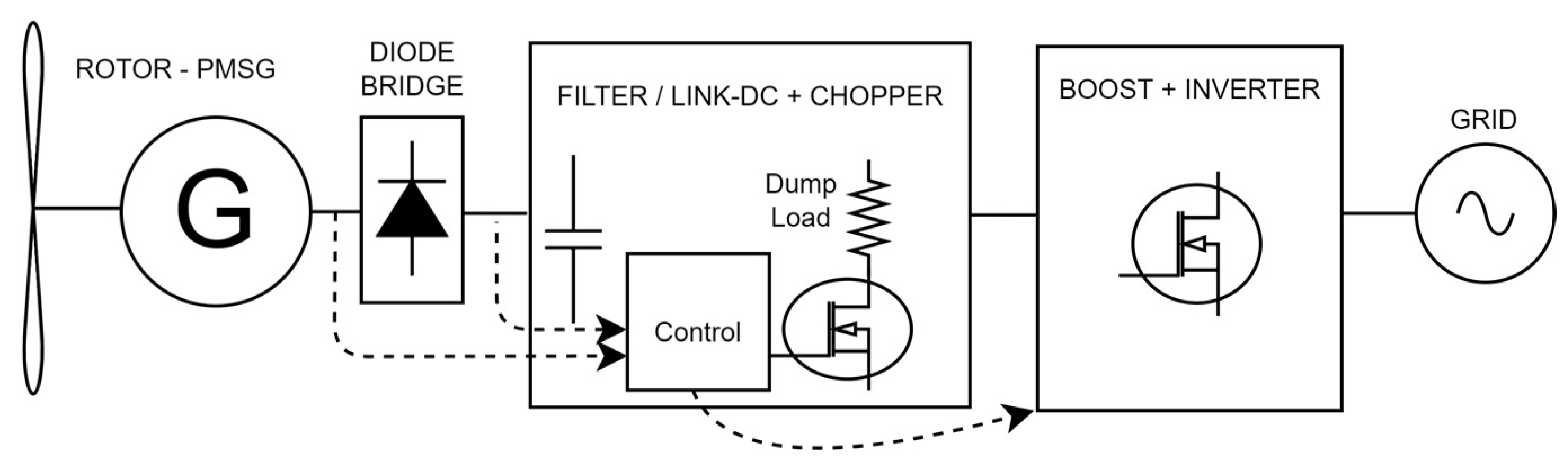
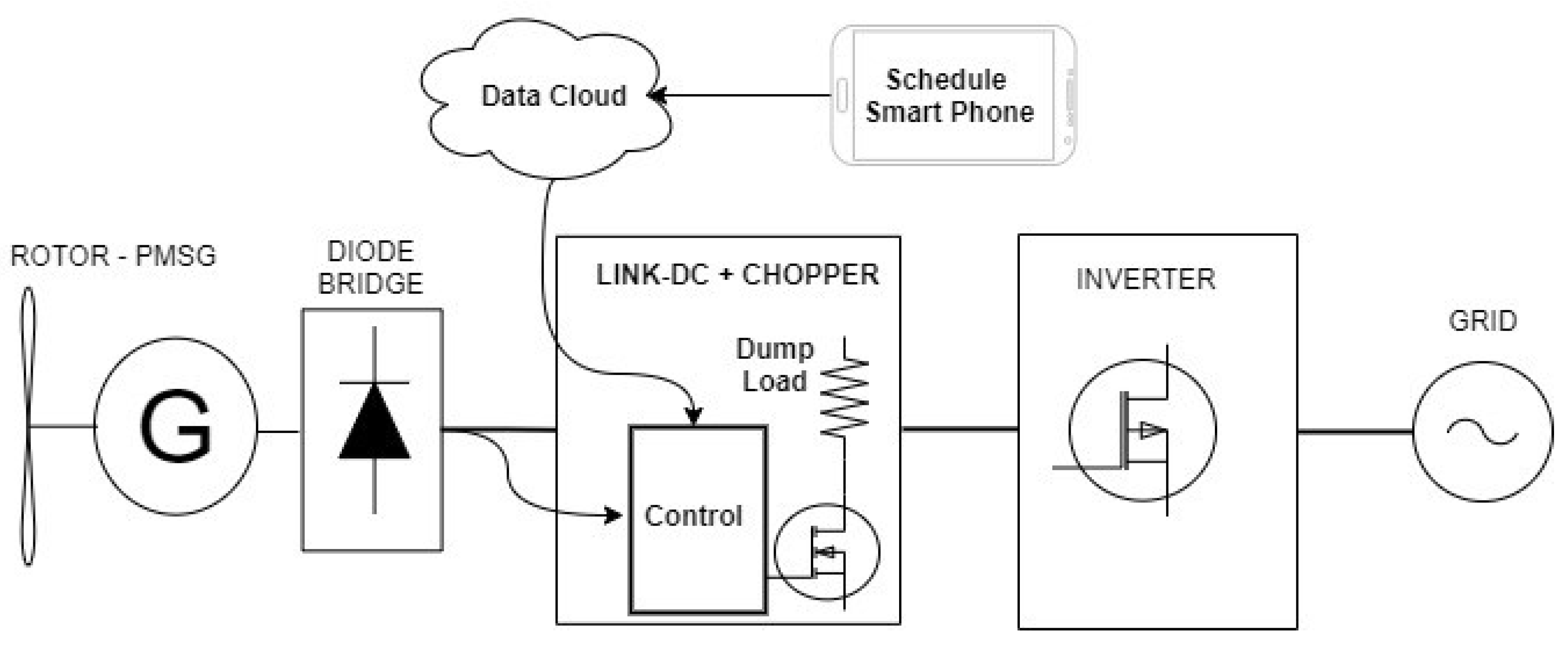
Configuration of the System under Review and Introduction to the Case Study

There is a great variety in terms of possible technologies when it comes to choosing a SWT, both for rotors and for electric generators, even in terms of the method of controlling the wind turbine. To limit the description of the electronics in SWTs, a type of wind turbine was selected, and more specifically a type of generator, which is the element that defines the type of control to be used.
Today’s SWT markets are primarily dominated by Permanent Magnet Synchronous Generator (PMSG)-based technology, which ensures variable speed operation [9]. PMSGs are, in grid-connected SWT conversion systems, completely decoupled from the grid; that is why they are considered part of systems with full-scale power electronics [10].
There are several configurations for power conditioning in a PMSG-based system, such as back-to-back converter, matrix converter, intermediate DC/DC converter, and line commutated silicon-controlled rectifier. However, most SWTs connected to the grid use the following configuration: rectifier, DC/DC converter, inverter [11], and chopper. The main layout of this configuration, shown in Figure 3, integrates the conversion modules, rectifier, filters, chopper and inverter to form a wind energy conversion unit, which is more flexible and more commonly used in small-capacity SWTs.
In Figure 3, within the power conversion scheme the “generator side converter”, in this case a boost converter, fulfills the functions of maximizing wind energy capture by the rotor, controlling power flow to the load side and optimizing the rotational speed.
Figure 4 illustrates the concept of the Maximum Power Point Tracking (MPPT) scheme, showing a family of aerodynamic power curves (function of the incident wind) and the set-point that the control places on the mechanical power curve transmitted, which is proportional to the cube of the rotational speed. The vertical axis is normalized relative to the nominal power of the turbine; the horizontal axis is normalized relative to the nominal rotational speed. Once the wind speed at which the nominal power is obtained is exceeded, the power control system should start regulating the rotational speed until reaching the set point. In SWTs, this is mainly through passive aerodynamic control [12,13]. Along with the foregoing, the ability to connect to the grid, usually without a battery system, causes the turbine to experience transient fluctuations due to gusts or other conditions, which requires that power control involve an electronic converter capable of mitigating harmful electrical deviations that can cause failures in power conversion. Therefore, the dynamic operating conditions of a SWT require the use of rapid response power electronics, switching in a “chopper” PWM pattern, capable of increasing the electromagnetic torque and controlling the variation.

2. Requirements for Applying Grid Connection in Each Component of a SWT

As mentioned before, the first review in this work analyzes how the application of grid connection affects each of the different components that are responsible for electrical generation in a SWT. Electrical generation starts at the electrical generator, flowing to the grid through two power converters: a generator-side electronic converter (a rectifier unit) and a grid-side electronic converter (inverter unit). However, the analysis of the influence of the grid connection will be performed the other way round, starting from the grid-connected inverter back to the electrical generator, as the grid is precisely the element that induces these effects.

2.1. The Inverter for the Grid Connection

This converter is in charge of maintaining (controlling) the electrical parameters of the grid connection, whether it is to an isolated grid or to the main grid. The essential function of this converter is to convert the DC output of the rectifier (or the DC/DC converter) into an alternating current with the power quality required by the grid. In addition, it can incorporate other functions, such as MPPT and power generation monitoring and management. Trends in the use of grid-side converters are reviewed below.

2.1.1. Inverters Designed Specifically for SWT Applications

Among the inverters designed specifically for the connection of SWTs to the grid, it is necessary to differentiate between general-purpose and proprietary devices (self-designed by SWT manufacturers).
Among inverters for general use, SMA’s Windy Boy was for a time an international reference that, when it ceased to be manufactured, was replaced as a reference by Power One’s inverters. After this company was acquired by ABB, it continued selling them, but ABB stopped manufacturing these inverters, offering only technical support. The same is true of other manufacturers such as Ginlong Technologies (Ningbo, China) and INGETEAM (Pamplona, Navarra, Spain), who stopped the production of their respective SWT inverters. Therefore, the presence of general-purpose inverters at a commercial level is becoming scarce.
The trend in proprietary inverters from specific manufacturers is different: in recent years, several manufacturers of SWTs that use their own inverter designs, such as the Skystream (from the company XZERES, Wilsonville, OR, USA) or the Windera (from the company ENNERA, Erreka, Guipuzkoa, Spain), emerged. This tendency towards the use of self-designed converters could be caused by the mentioned shortage of general-purpose inverters for SWTs and marks a completely different direction from what happens in other sectors, such as PV, where the use of general-purpose converters is the most common practice.

2.1.2. General Purpose Photovoltaic (PV) Inverters

Given the scarcity of proper wind inverters and the abundance of PV inverters on the market, a highly desirable possibility is to adapt PV inverters in order to use them with SWTs. The use of solar PV inverters has the advantage of providing equipment at a relatively low cost, due to the scale of production of PV technology. However, their use in SWT applications has some effects on the SWT itself, which are analyzed in this Section.
A PV inverter can be divided into two different converters: the grid-side converter and the generator-side converter. Although the grid-side converter can be considered similar for both technologies (PV and SWT), this is not the case for the generator-side converter, where the control algorithms are different. The differences derive from the different behavior of the two generation technologies. In particular, issues such as the characteristic voltage–current curves and response times are different between both technologies, which must be taken into account in the configuration of the equipment. The variability of the corresponding resources (solar radiation and wind) is also different, which can affect the inverter’s operating parameters.
It should not be forgotten either that, while a PV generator can remain in open circuit (no load) without suffering any damage, many SWTs will not allow this mode of operation on a continuous basis, which also requires consideration of functional aspects related to the safety of the SWT. Therefore, it would be necessary in these cases to incorporate an electronic protection system that prevents the SWT from operating unloaded, as described above.
As a result of this analysis, the following requirements can be identified for a generator-side converter within a PV inverter:
-
Frequency drop—power regulation in AC-coupled microgrids: in the case of AC-coupled microgrids, it is common to use frequency drop in order to regulate the power generated by the inverter [14]. Based on the frequency variation, the generator-side inverter will move the working point of the PV generator, changing the working voltage so that the current is adjusted to the desired value. However, as this characteristic is different for a SWT, this regulation might not work as expected.
-
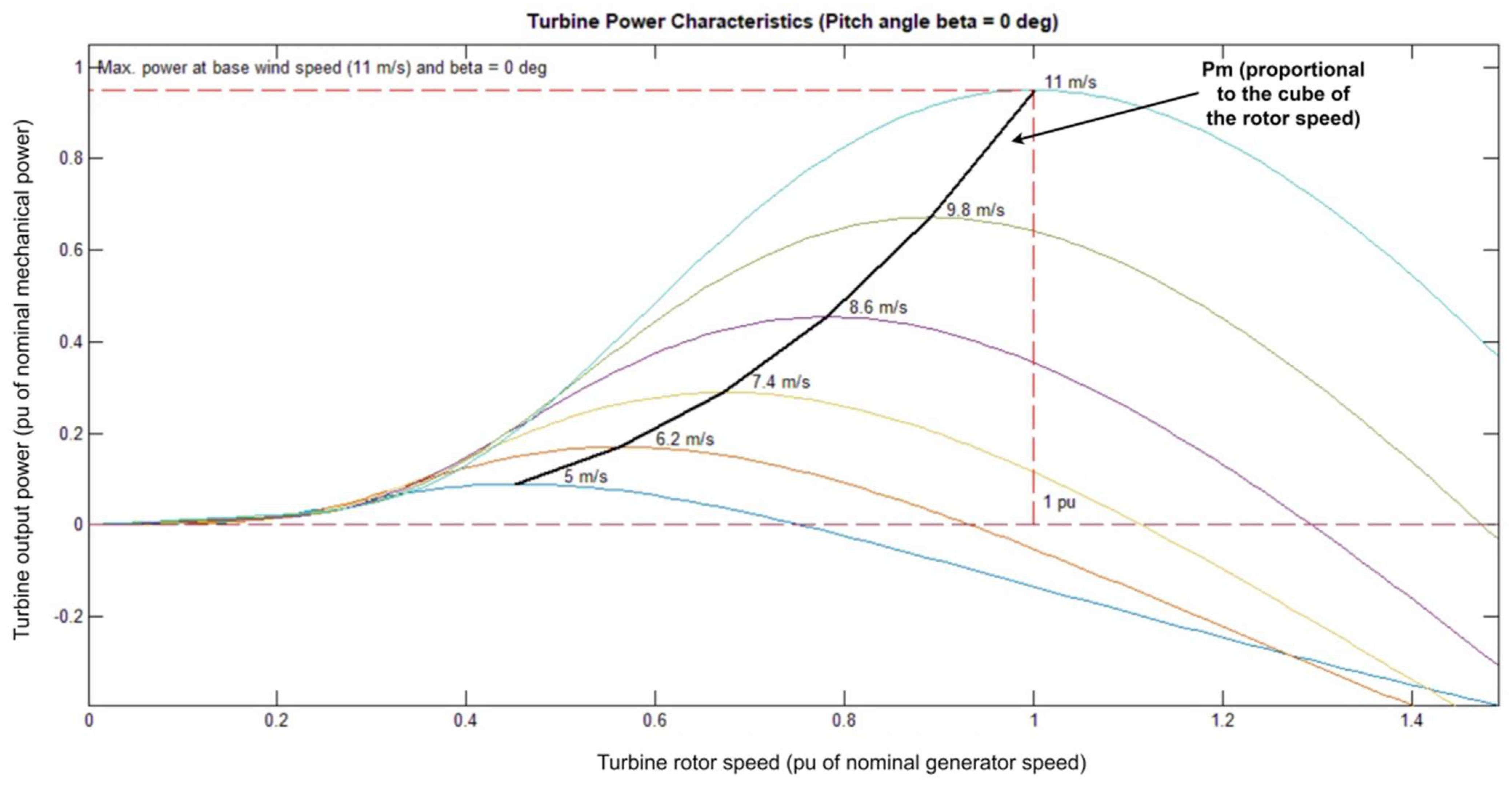
Maximum Power Point Tracking (MPPT): in the same way, the inverter will move the working point of the PV generator to track for the maximum power point, changing the working voltage according to the PV’s I–V curve. However, as this characteristic is different for a SWT, this regulation might not work as expected either. The variability in wind speeds creates a challenge for turbine control, because the aerodynamic efficiency of the turbine rotor is related to maintaining an optimal relationship between current wind speed and rotational speed [12]. Sudden gusts of wind can also cause an increase in the fatigue load on turbine components that might reduce the lifetime of the turbine.
-
Time response: PV generation has no inertia, whereas SWT generation does. This means that the two methods will have different time responses, which might affect the correct functioning of the converter.
-
Waiting time: the time until the inverter starts producing, usually in the tens of seconds (during which the generator is unloaded). The inverter control routines may cause periods of disconnection from the grid, which are allowable for PV applications, but which might result in conditions that compromise the integrity of the SWT due to situations where there might be high voltage and overspeed in the wind turbine, requiring an overvoltage device.
-
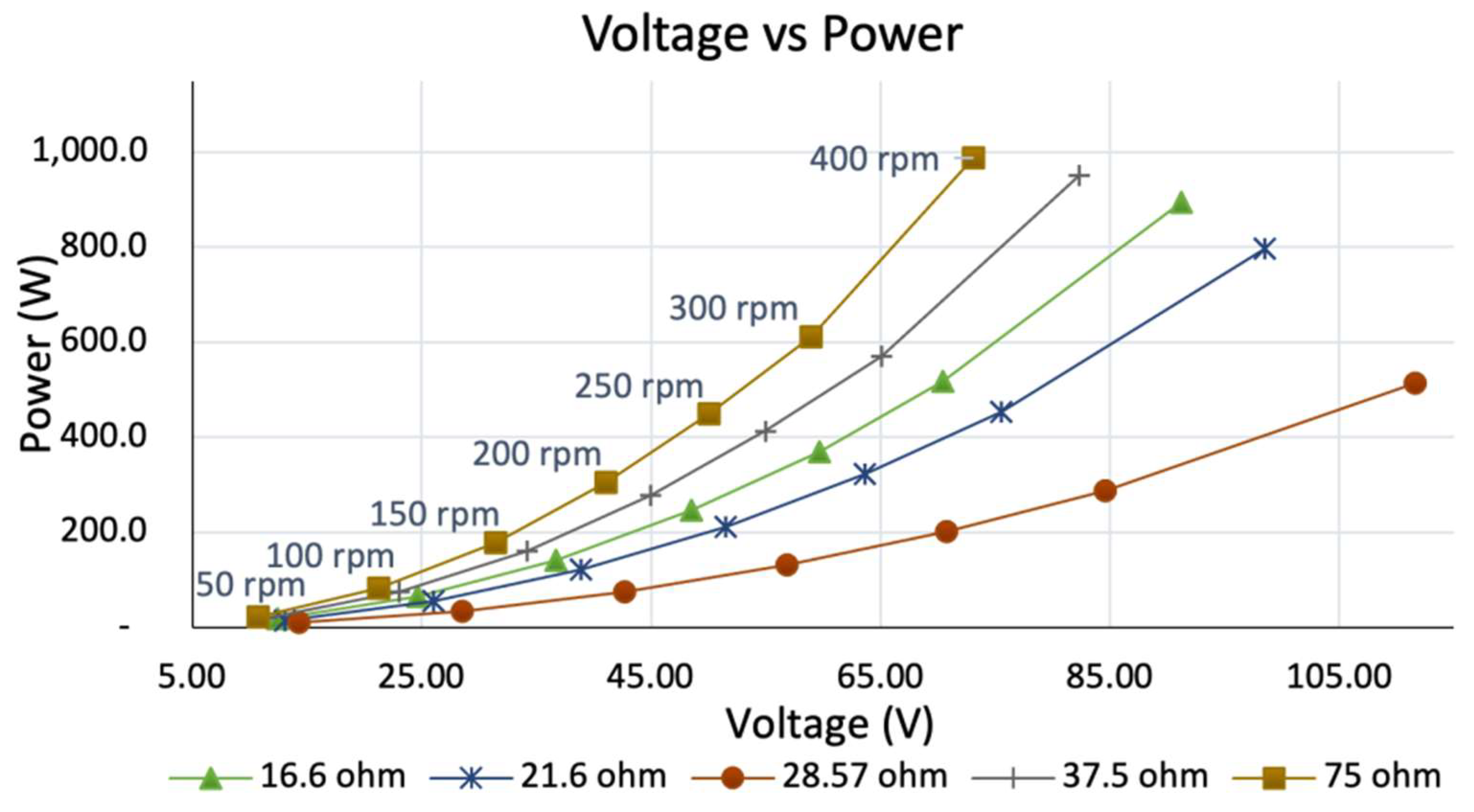
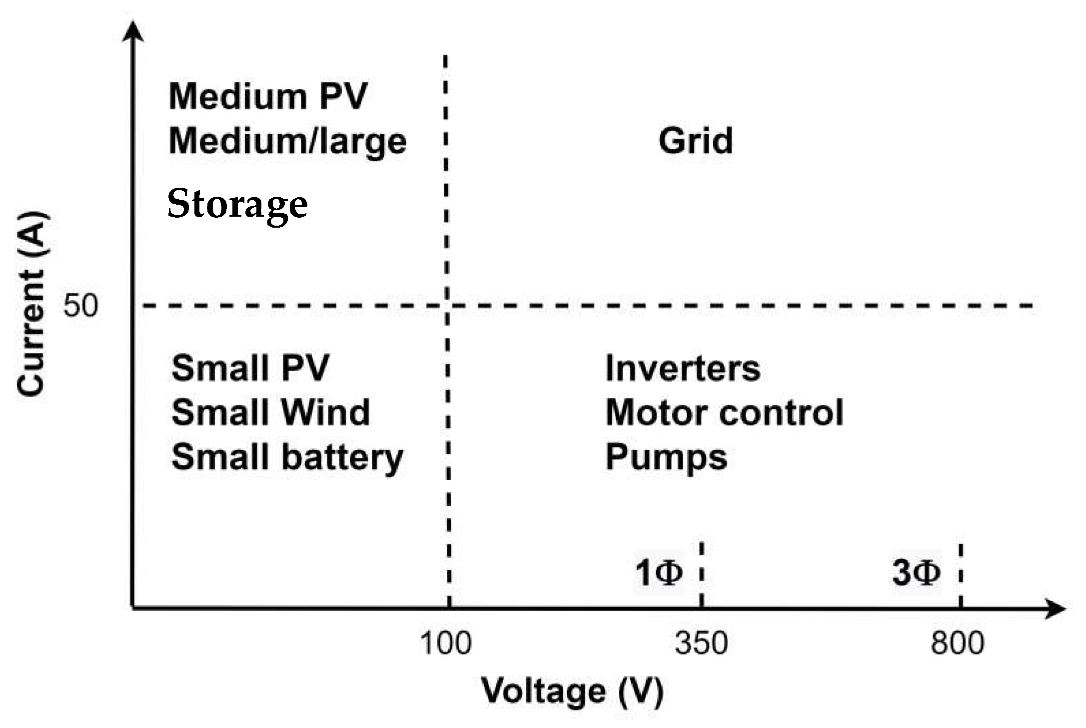
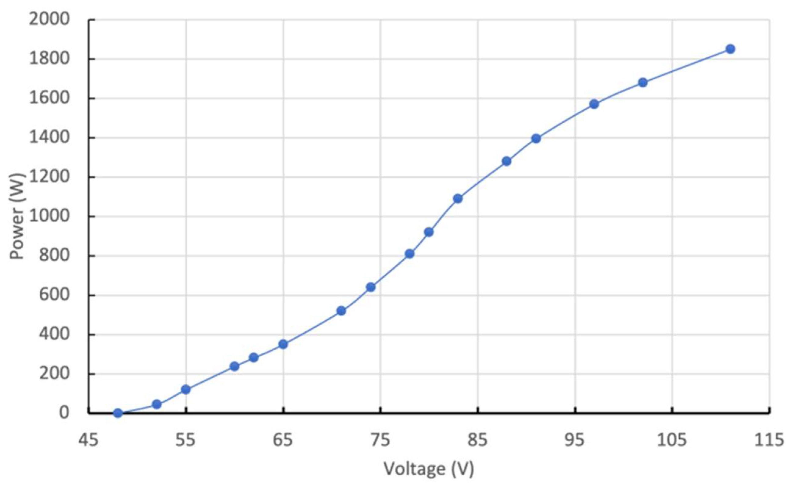
High DC voltages: in Figure 5 it is shown that inverters for grid-connected power generation usually work with voltages higher than 100 V, up to hundreds of volts [15]. SWTs designed for battery charging applications usually use 12, 24 or 48 V as nominal voltages, which are far from the voltage range used for grid connection. This effect means that some adaptation will be needed for voltage matching, either at the SWT’s generator or at the power converter, or both.
-
Outages: in grid-connected systems, outages have to be considered. In IEC 61400-2 standard [16], it is stated that “Electrical network outages shall be assumed to occur 20 times per year. An outage of up to 24 h shall be considered a normal condition”. This fact equally necessitates overvoltage protection for the SWT, and adds the need for it to be able to work in continuous mode.

2.1.3. The Inverter in the Case Study

The inverter used in the case study was a commercial single-phase inverter originally designed for solar power applications. It was manufactured by Omnik New Energy, model Omniksol 1K-TL2-M, with a nominal power of 1000 W, nominal input voltage of 360 V DC with a maximum of 500 V, and single-phase AC output of 220 V, 50 Hz. Omniksol inverters offer a wide voltage range for the input DC voltage, making them interesting for wind power applications. The device is powered from the AC side, allowing it to stay powered also during low wind conditions. The inverter uses a MPPT-based control scheme with an input DC voltage range of 60–400 VDC, 155–400 VDC at nominal power [17].
The control algorithm settings are fixed and cannot be adjusted by the user. The Omniksol inverters also include a set of protections, both on the DC side and on the grid side: overvoltage, current protection and ground fault monitoring.
This inverter is no longer manufactured, and the company has retired from the solar industry [18]. There are some monitoring features on the device that require access to a cloud service that no longer exists [19]. The inverter was usable without these features, using the factory settings for the purpose of this case study.

2.2. The Power Controller

This presents the necessary electronic converters that are required to adapt and control the power output of the electrical generator before connecting it to the inverter. As stated in previous sections, SWTs will normally generate power using a three-phase AC generator, whose output is then rectified into DC [12]. At minimum, a rectifier is needed to convert the AC output of the generator into a DC input for the inverter. Rectified DC power is often referred to as “wild direct current” and is what is typically regulated by the electronic control and protection equipment described in this section. Optionally, there might be a DC/DC converter to adapt voltage ranges, and it is compulsory in the case of SWTs for there to be an overvoltage protection device [20]. The effects of grid connection on both the overvoltage protection device and the rectifier are briefly assessed below.

2.2.1. Overvoltage Protection

Rotational speed has a direct relationship with DC voltage in a SWT, and sudden bursts of speed can cause voltage spikes that can also damage the electrical components. For this reason, in [16] it is stated that “the SWT shall be designed in order to keep all parameters within their design limits under all design load cases. This shall be achieved through an active and/or passive protection system included in the design. In particular, there shall be means to prevent the rotational speed design limit nmax from being exceeded”.
In low-power turbines, given the cost and complexity compared to an active pitch system, the control action is performed in most cases by a mechanical passive system called Furling, analyzed in several studies and widely applied in most SWTs [12,13]. Furling has the disadvantage of not being able to counteract the electrical consequences (overvoltages) of sudden increases in rotational speed due to changes in wind speed in a completely effective way due to its dynamics, especially in extreme conditions, which is more problematic if combined with a “loss” of load or in the electrical grid.
For this reason, a redundant electronic active system is commonly used for overvoltage protection in SWT. It is composed of a power converter (chopper) and a resistive load (dump load), which are used to maintain the voltage (rotational speed) within a specified range, preventing the SWT from exceeding the rotational speed design limit. A dump load is an extra resistive load that is connected to the generator when the voltage reaches too high a level [21,22]. In grid-connected devices, the dump load can act as a protection mechanism if the grid is lost [20].
In the case of SWTs under 1 kW, this device is commonly the only one [23].
The identified effects of grid connection on the overvoltage protection device are:
  • It is mandatory: as derived from analysis of the effects on the PV inverter (2.1.2), it is mandatory to have an overvoltage protection device for the times when there is no load connected to the SWT, such as an outage in a grid-connected SWT.
  • It has to be able to work in a continuous mode: also derived from the referred analysis; grid power outages may last up to 24 h in normal conditions, which can be considered continuous mode operation for the overvoltage device.
  • These electronic overvoltage protection devices are common for SWT battery-charging applications, where there is a stable voltage reference from the battery and the voltage variations are slow and small, as the battery maintains voltage stability. This is not the case in grid-connected turbines: in the case of an inverter waiting time, for example, the SWT will be open-loaded and the DC voltage might change abruptly if the wind is high enough at that moment. In that case, it is possible that the control algorithm of the electronic overvoltage protection device will try to diminish the rotational speed sharply, delivering a (relatively) large amount of power to the resistive load. This action will produce a sudden brake in the SWT, with corresponding fatigue loads. This might be thought of as an emergency system, but will certainly highly decrease the lifetime of the SWT if it is used as a normal condition.

2.2.2. Controllers for Wind Turbines: Rectifiers

The signal could be rectified using different approaches, such as a bridge rectifier, six-switch controlled rectifier, or others (such as a multilevel converter, matrix converters, a back-to-back device, etc.) [10]. The most common option for SWTs is the bridge rectifier [24], due to its simplicity and affordability [25]. However, in this option, control is not available, which would require the addition of a DC/DC converter before the grid-side inverter [25]. This may result in high losses if the DC voltage is low [24]. The power extraction scheme is typically incorporated into the control strategy, either the DC/DC converter or the inverter, to achieve high efficiency of conversion [11]. The bridge rectifier is often followed by a filter [10].
No special effects were identified for the rectifier, other than the higher voltage needed in the DC bus for the inverter (see Figure 5).

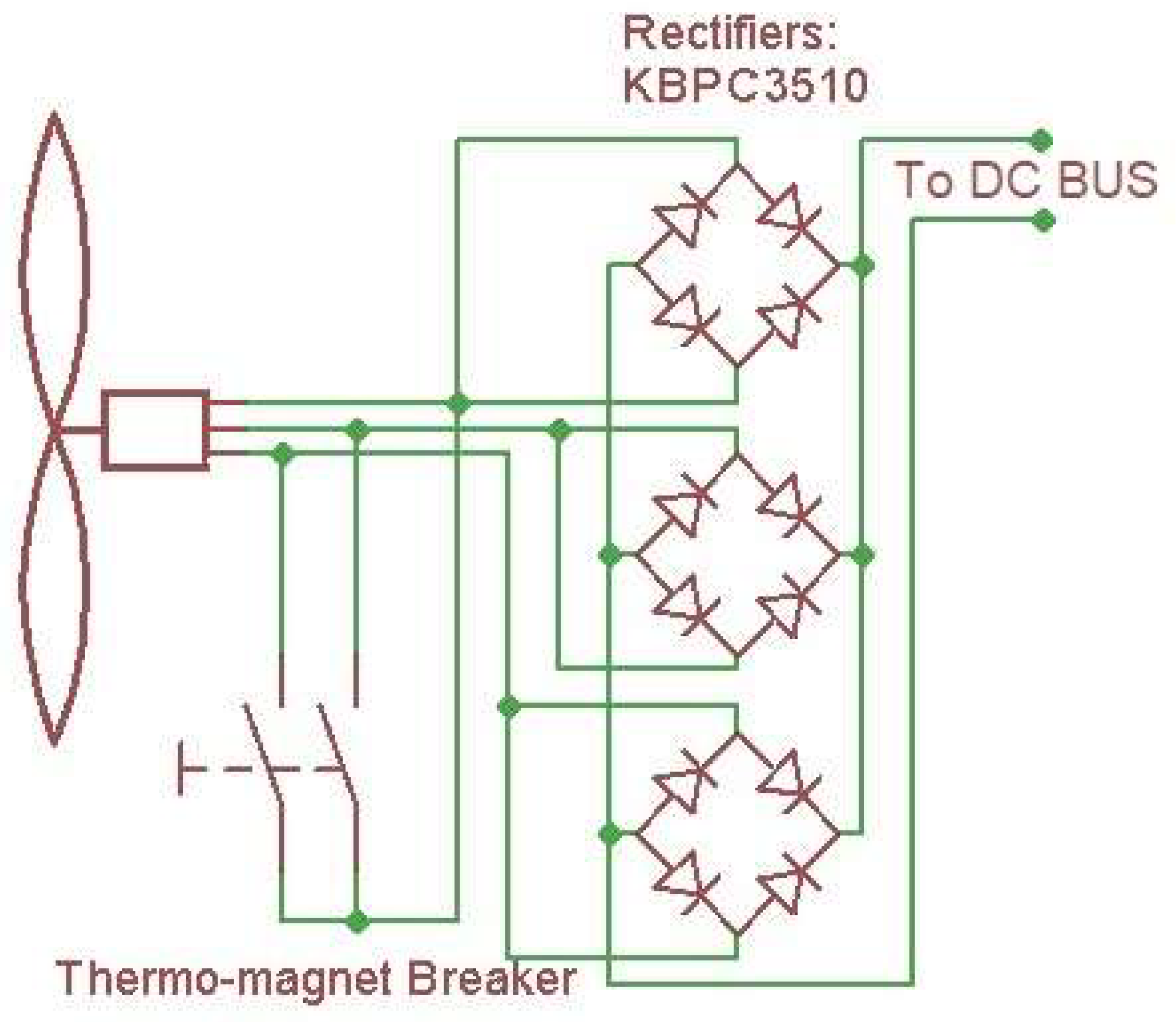
2.2.3. The Power Control in the Case Study
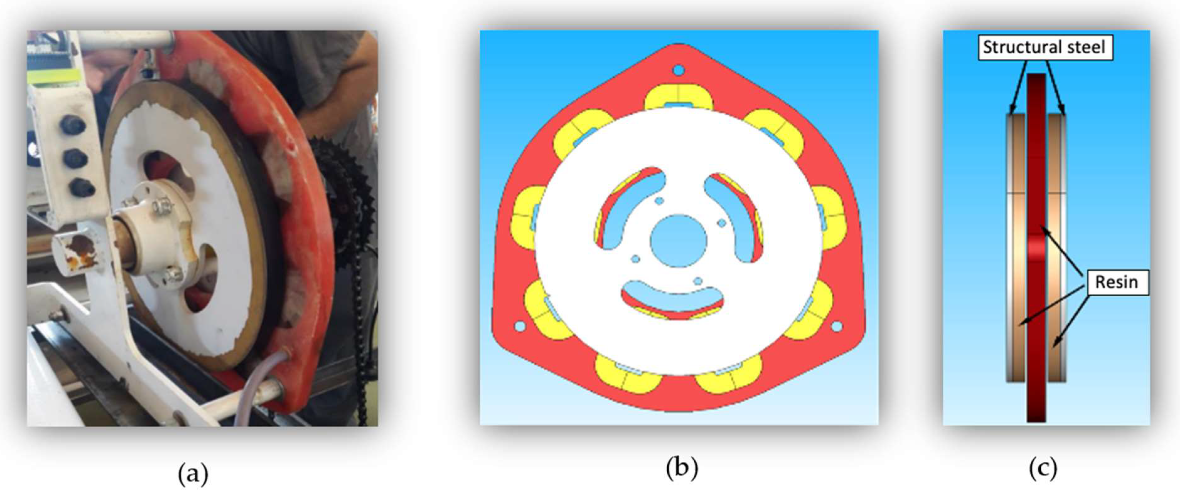
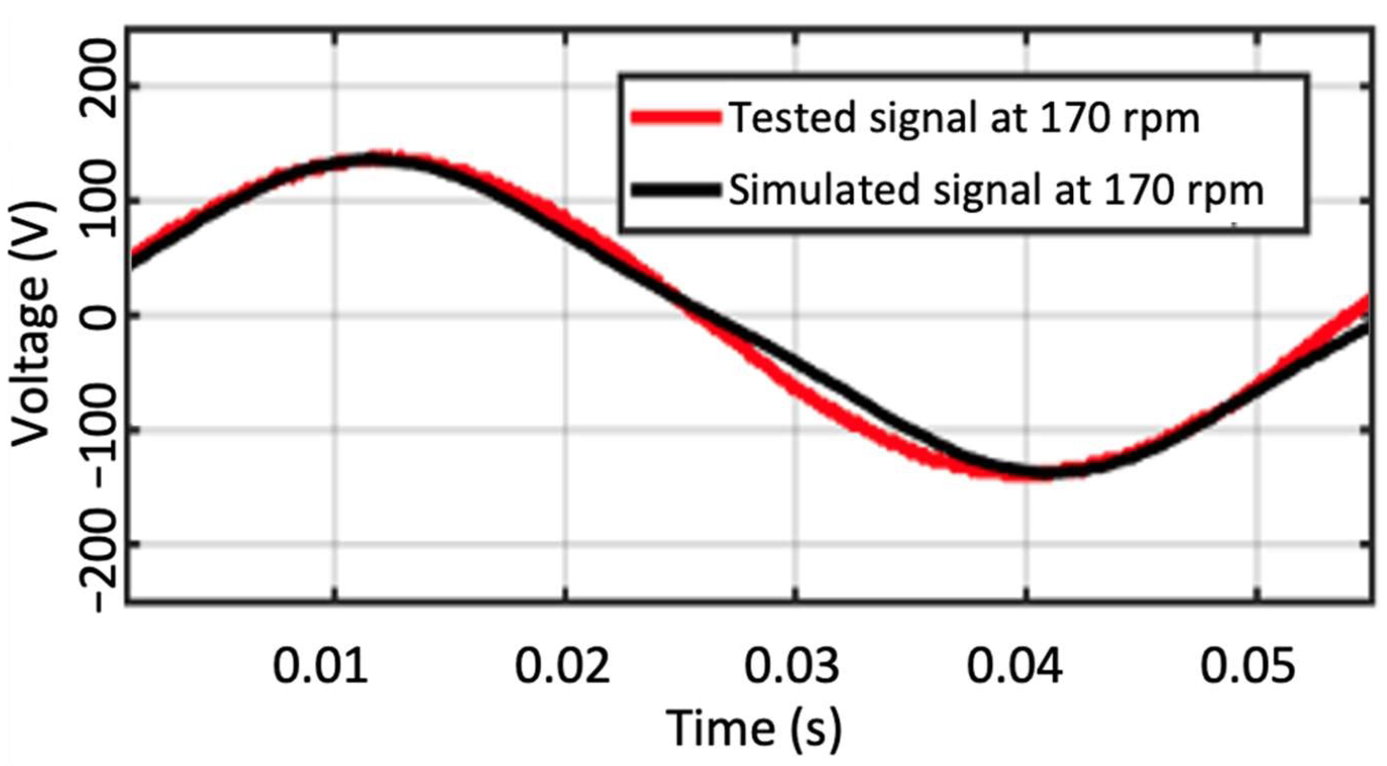
The rectifier used in the case study was a standard diode-bridge rectifier, depicted in Figure 6.

2.3. The Generator

Even though large-scale wind turbines can be found using both Doubly-Fed Induction Generators (DFIGs) [26], and Permanent Magnet Synchronous Generators (PMSGs), SWTs are usually composed of a 3-phase PMSG [27]. This is because PMSGs are low-speed machines with no gearboxes, which are easy to control using a full converter [28]. DFIGs are capable of operating at variable speeds with active/reactive power controllability [29], and their power converter capacity is between 25% and 30% of the nominal system capacity. However, a gearbox is needed to increase the rotational speed in the DFIG shaft.

The Generator in the Case Study

The Eolocal electric generator was redesigned using a solar PV grid inverter to produce higher voltage output, in order to be able to connect the AG700 wind turbine to the grid. This redesign was given the model number AG1000.
Eolocal’s 1000 W electric generator is based on a Hugh Piggott design [30]. The generator structure is an axial flux machine, which is easy to build and is less costly [31] compared with radial flux generators. This generator consists of a stator disk between two permanent magnet rotors. The generator was tested in the INTI laboratory and modeled at INEEL. Figure 7 shows the generator prototype in a test bench at INTI, where the electrical parameters of the generator were measured, and its 3D model.
The performance parameters were obtained and mutually verified via testing and modeling. Table 1 shows the generator’s characteristics.
Figure 8 shows the voltage waveform of the generator. The black line represents the simulated line-to-line voltage; the red line corresponds to the experimentally tested voltage.
The average error in RMS voltage between the simulation and test values, for a speed range from 114.6 rpm to 423 rpm, was 1.36%. The simulation model was run under a set of load scenarios, which consisted of a resistive array in “Y”. The results, in a speed range from 50 rpm to 400 rpm, are shown in Figure 9.

2.4. A Short List of SWTs Below 5 kW and Their Main Characteristics for Grid Connection Capacity

A short list of SWT grid-connected models was selected within the low-power range (less than 5 kW). For these models, the main characteristics relevant to this study were identified, when available. The results are shown in Table 2.
Some of the conclusions that can be derived from Table 2 are:
  • Generator: PMSG technology dominates. The number of pole pairs is quite high to avoid the need for a gearbox. The output voltage of the generator is higher than 200 V.
  • Overvoltage protection device: the chopper plus dump load is always present; other devices (either mechanical or electronic) are also present in some models.
  • Braking system: usually, the overvoltage protection device is also used as a braking system.
  • Controller: some of the models include a MPPT controller.
These results ratify the main conclusions derived from the first review, in terms of the high voltage needed in the DC bus for grid connection, along with the requirement for an electronic solution for the overvoltage protection device.

3. A Review of Existing Options for Overvoltage Protection

From the review in Section 2, it follows that the electronic overvoltage protection device is the paramount necessity for the grid-connected application of SWTs, particularly when using a PV inverter. The following is a review of the existing electronic equipment for this purpose in SWTs. The review includes:
-
Proprietary products, i.e., manufactured in-house and used exclusively by manufacturers of SWTs;
-
Off-the-shelf products existing at a commercial level, i.e., equipment manufactured by electronic equipment manufacturers, and which can be used in different wind turbine models;
-
Free or open source designs, i.e., designs that are available in the literature and/or on the Internet, and that allow anyone to manufacture them.
In no case does this review pretend to be exhaustive, but only aims to give an idea of the available solutions.
The electronic overvoltage protection device that is most common in SWTs is the one presented in the previous Section 2.2.1, formed by a chopper and a dump load. However, voltage can be controlled in other ways as well. One solution would be the use of an electric brake connected to the generator [42,43]. A different approach is to change the control mechanism of the generator at high wind speeds. The goal with these control schemes is to switch from maximum power point control to a different control scheme at high wind speeds, in order to reduce the produced power and protect the generator and control electronics [44,45,46,47].
Finally, there are proposals such as the one in [48] where the control system provokes short high current pulses based on thresholds in order to maximize the electromagnetic torque relative to the mechanical one and to control the machine, inducing in it a stall by decreasing the blade tip speed ratio. In this case, both the generator and the power electronics should be sized for this purpose.
Some of the manufacturers presented in this Section also appear in the review in Section 2.1.1, as they manufacture both the inverter and the overvoltage protection device; however, there are some others that appear at this point that were not present as inverter manufacturers.

3.1. Proprietary Devices

Some of the more popular SWT models use proprietary in-house manufactured control systems. Examples include the Skystream, manufactured initially by Southwest Windpower and later by Xzeres, and the Windera, a wind turbine manufactured by Ennera. The following diagram in Figure 10 shows the solution adopted by Ennera for the electronic regulation of the Windera wind turbine, which includes the following elements: a safety element to short circuit the wind turbine (crowbar); a rectifier to convert the AC output into DC; a DC/DC converter (booster) in charge of monitoring the maximum power point; a circuit to protect against overvoltage (brake chopper); and the inverter that converts the DC into AC.

3.2. Commercially Available Devices

Below are three of the existing commercially available overvoltage protection devices.

3.2.1. PowerOne Turbine Controller

This device was designed by PowerOne (later acquired by ABB). ABB considers it “legacy” equipment [49], and still offers it on its website but expressly indicates that the company does not devote resources to its design. It is intended to work with the Aurora family of inverters, also designed by PowerOne, but can be purchased independently for general use [50]. The wind interface consists of a diode bridge rectifier, a power control system derived from the tipping resistance (diversion load) and protection elements against overcurrents (fuses) and surges (crowbar).

3.2.2. Morningstar TriStar Turbine Controller

Morningstar TriStar MPPT controllers are designed for solar PV applications. However, they can also be made compatible with other DC power sources, such as wind and hydro turbines, in the range of approximately 3 to 13 kW, by placing equipment in parallel [51].
The TriStar MPPT controller tracks the power and DC voltage of the turbine. The TriStar MPPT configuration (150 V and 600 V) includes a voltage versus power curve that is entered for the turbine used. The controller continuously adjusts the wild DC power input to operate according to the voltage versus power curve. These controllers are designed to be able to start up whenever the input voltage is higher than the battery voltage and lower than the absolute maximum operating voltage (145 V for the 150 V controller, and 525 V for the 600 V controller). The following graph in Figure 11 shows an example of an input DC voltage versus wind turbine power curve, programmed into the controller and used as a reference.
The TriStar MPPT controller system also requires a means of keeping the turbine rotation speed under control during periods of voltage regulation. One option is to use the TriStar Dump Resistance Controller. This configuration allows the TriStar MPPT controller to run at full power (mass charge mode) continuously while the tipping resistance controller manages the regulation voltage. This maintains continuous charging operation at all times.

3.2.3. Voltsys Wind Turbine Controller

Voltsys, an Irish company that provides online support to customers worldwide, has been designing control systems and providing inverter solutions for small wind turbines since 2008 [52]. They worked closely with ABB and modified their controllers to override the MPPT tracking in solar inverters. Their controller stores the wind turbine power curve, instead of frequency, and manages the inverter via Modbus. Using this system, they continue to supply controllers and inverters for small wind and micro hydro systems. Their system is approved by FIMER [53], an Italian company that is now the fourth-largest solar inverter manufacturer in the world and that acquired ABB’s solar inverter business in 2020 [54]. They can provide fully functional wind and hydro inverters using the ABB solar product range from 1.2 kW up to 120 kW and beyond. Their systems can also be used in off-grid applications.
Voltsys designed a range of intelligent interfaces to rectify the wild AC from a turbine for use with inverters, manage turbine speed with dump loads, and provide data logging and inverter overvoltage protection. A DC dump load can be configured either as a variable load using PWM or with on/off set points. Both options are fully configurable and can be used to manage turbine overvoltage or to slow a turbine during gusts. In a grid failure, the controller provides a load with on/off set points only. Controllers come with a range of options for rectifier and capacitor sizes, depending on power and working voltage. The controller can respond to grid or inverter failure and shut down the turbine accordingly.

3.2.4. Midnite Controller

Midnite 250 controllers, conceived for solar MPPT, can be configured to work with wind turbines by setting up the SWT parameters, and use a logic connection to their Clipper models (AC or DC) up to 4 kW [55].

3.3. Freely Available Designs

There are several free-to-use designs available for the regulation and control of SWTs. This equipment is usually designed for lower power wind turbines (typically less than 1 kW), due to the reduced risk caused by lower voltage and current. The following is a description of one proposed by Wind Empowerment [56]. A second available free design is included, constituting a redundant system of overprotection to guarantee that, in the case of failure of the corresponding regulation system, the wind turbine does not remain unloaded, which could cause damage both to the control electronics and to the wind turbine itself [57].

3.3.1. Wind Empowerment

This prototype load controller is the result of a project that ran between April and September 2016 conducted by the members of Wind Empowerment [56], an organization for the development of small locally built wind turbines. In this network, the Piggott wind turbine became the standard because its construction requires only basic materials, tools and skills. Thanks to the simplicity of its design and its open source license, it has been promoted all over the world, particularly in countries where the electricity supply is not available or affordable. It includes regulation via pulse width modulation (PWM), and is designed for DC voltages of 24/48 V. The system compares a sample of the rectified output voltage, using a comparator, with the reference voltage for 24 or 48 V operation. Once the threshold is exceeded by a given hysteresis, power MOSFETs placed in parallel will activate and direct the power into a resistive load.
In Argentina, improvement of the conditions of rural electrification is carried out through the work “Open Source Technology, a sustainable solution to achieve energy for all in the global south” [58] using the philosophy of Open Source Hardware Technology. The technology adapted by this project is based on a system developed by the Automatic Control Laboratory (LCA-INTEQUI) in France [59], adapting this system to the voltage and current levels for wind and solar systems. Figure 12 introduces the hardware of this system, whose main characteristic is to fulfill the functions of regulator (overvoltage) and wind brake plus data logging at a low cost.

3.3.2. Overvoltage Relay Protection

This redundant protection design created by PowerOne—ABB (Zurich, Switzerland) was presented earlier (Wind Box Interface, Aurora inverter). It is meant to guarantee that there will be no damage to the electronics or the wind turbine in the event that the electronic regulation system enters into an unexpected mode of operation that leaves the wind turbine unloaded, with the consequent risks of speed increase and overvoltage. The system is a simple voltage relay set to switch when wild DC voltage reaches a designated overvoltage protection limit. The operation scheme is shown in the following diagram in Figure 13, where two options are shown: one (on the left) in which the wind turbine is left open if the network is lost (this would be suitable only for wind turbines with internal over-speed protection) and another (on the right) in which some dump loads are connected (labeled Dump Load) in the event of network loss [57].

4. An Open Source Proposal for Overvoltage Protection for a 1 kW SWT: A Case Study and Preliminary Field Results

Therefore, the need arises to establish, as a minimum, the development of a protection system that guarantees the safe operation of the system. For this purpose, an overvoltage protection board was developed at the National Technological University, Regional Faculty of Neuquén (UTN-FRN). This board is installed at the input of the grid inverter, which controls the diversion of the generated energy towards a dump load, in order to control the system at all times. The operating logic of this system yields smooth control over this action, in such a way that it does not cause sudden drives or diversions that compromise the mechanical integrity of the wind turbine over time. This proposed solution is described in the following sections.

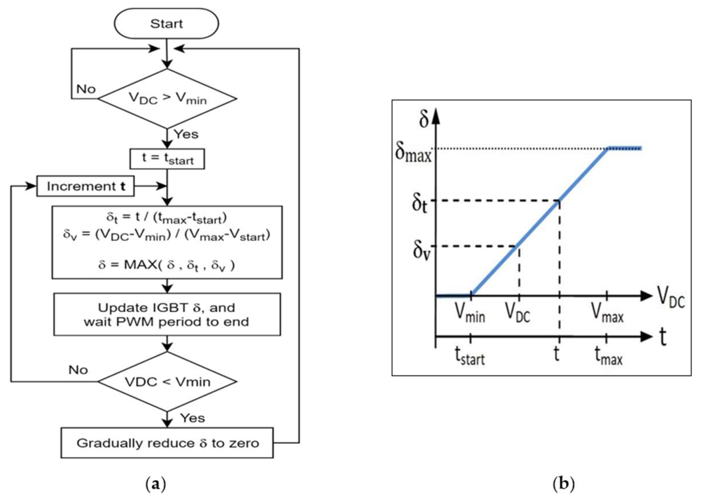
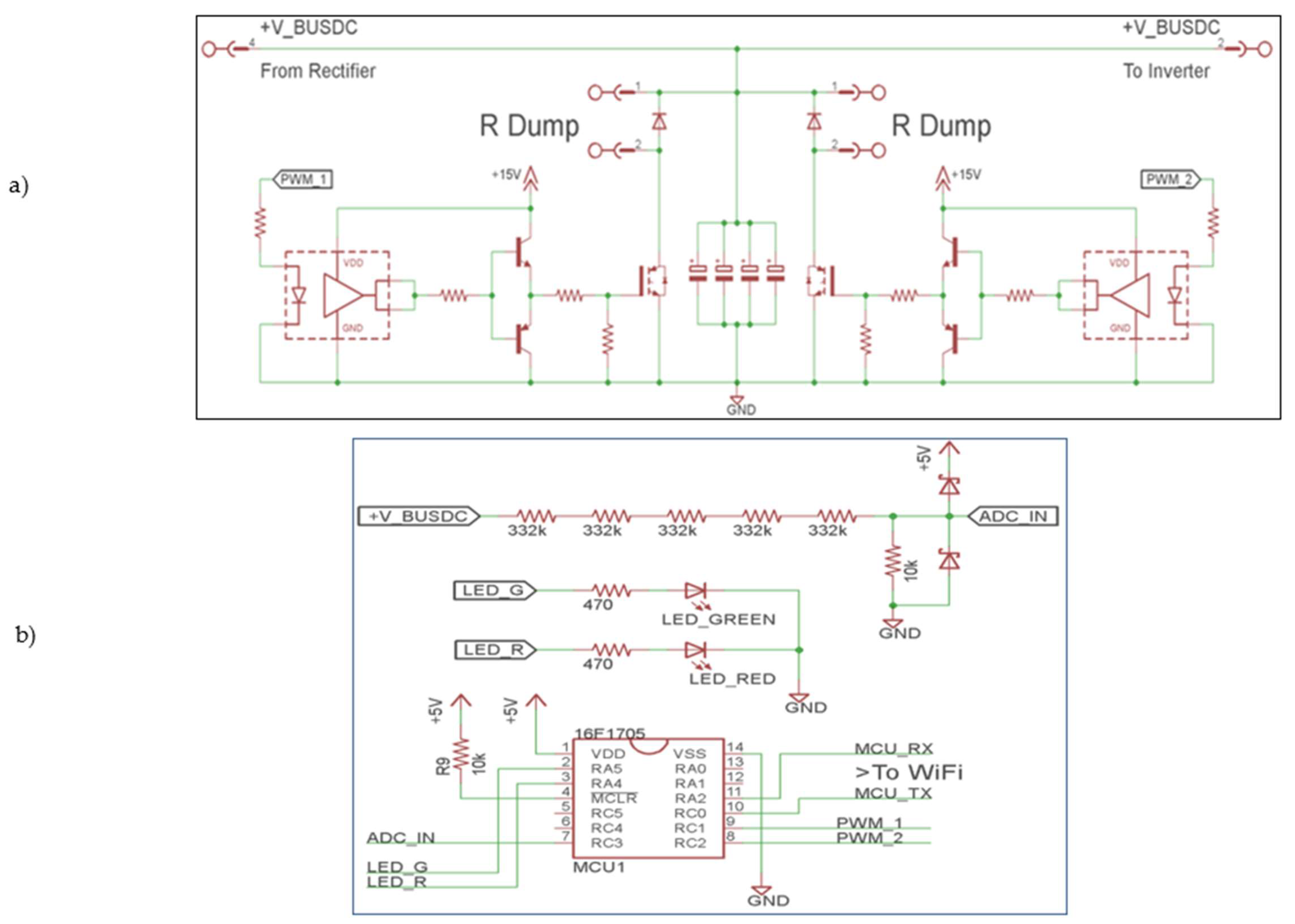
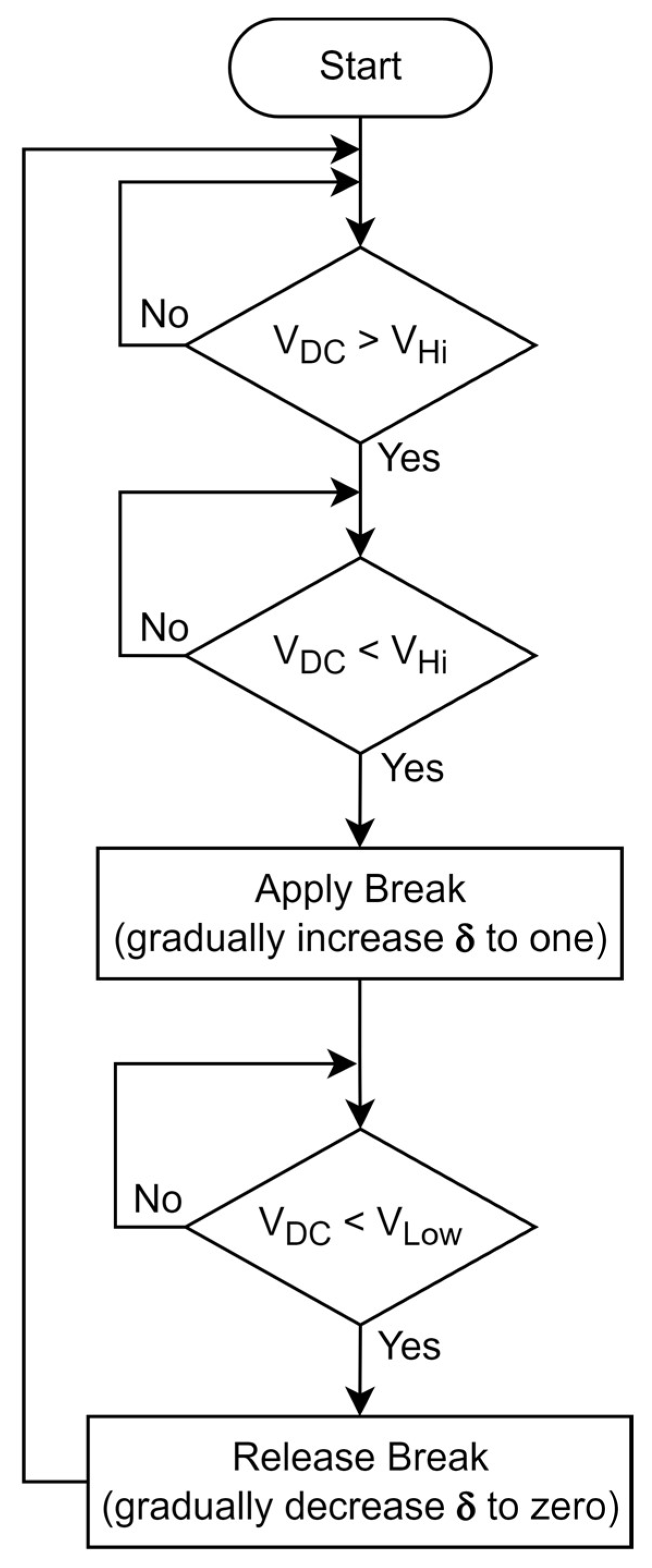
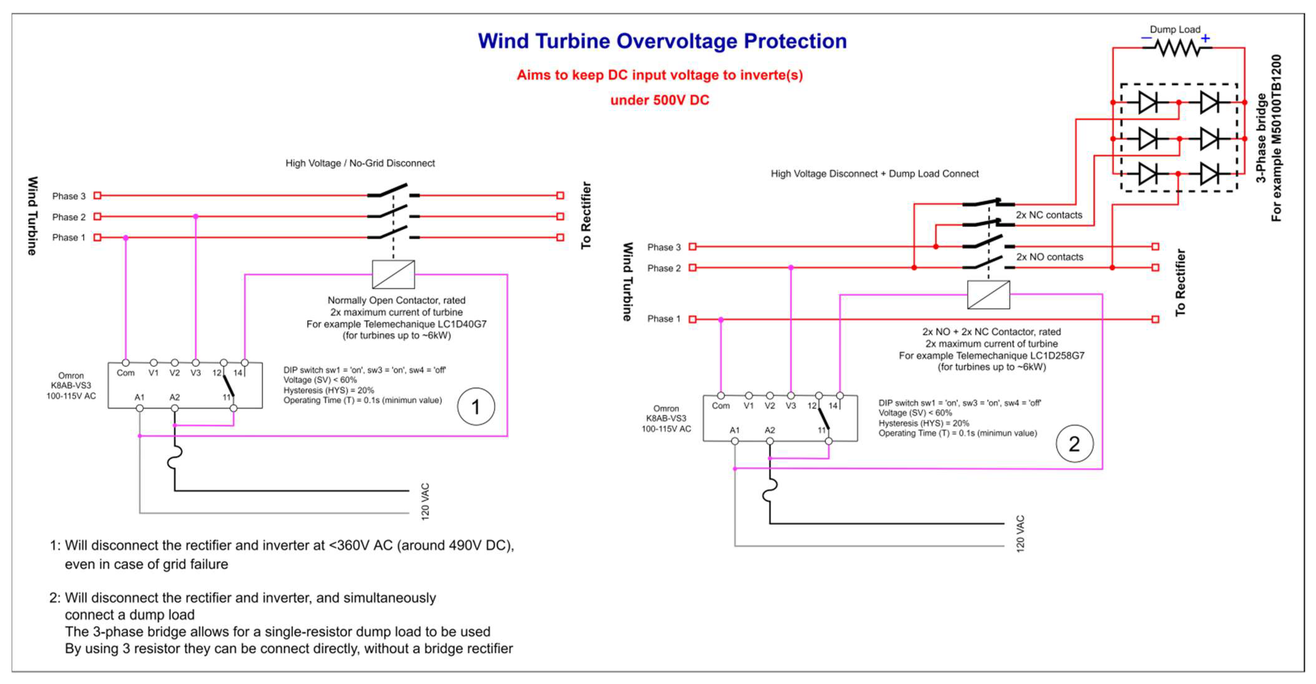
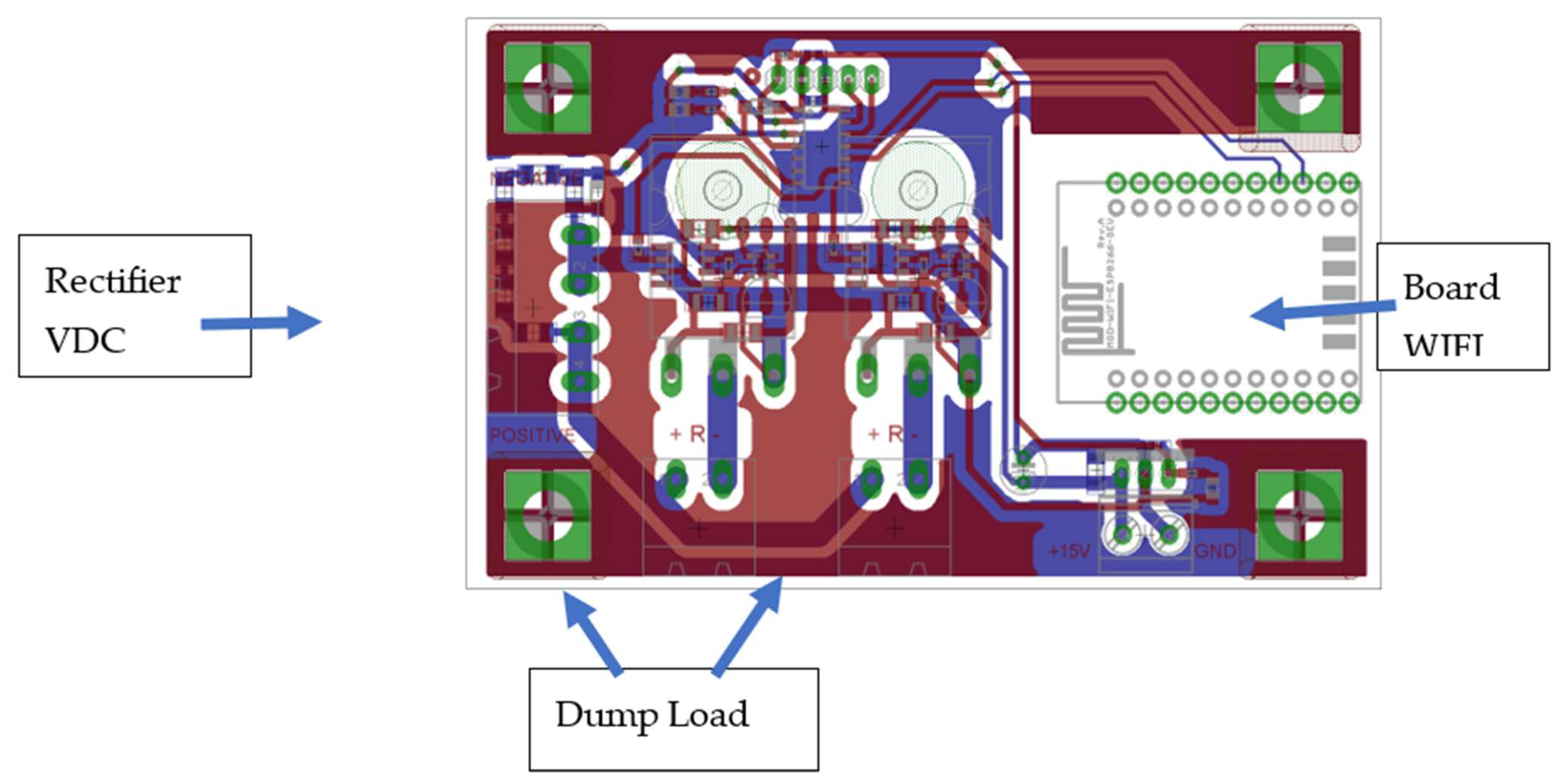
4.1. Proposed Solution for Overvoltage

This work, unlike that of Catuogno adapting the LCA-INTEQUI technology [58], is a local development designed for SWTs connected to the grid that may use inverters of the solar type, with the fundamental purposes of overvoltage protection and flexibility for end-user programming. This is likely to be possible using LCA-INTEQUI’s open hardware, but it would always require some programming or adaptation that may not be carried out by the end-user.
As indicated in previous sections, the problem that is addressed with this solution comes from DC surges after rectification of the wind turbine’s AC electrical output, along with the difficulty of finding a product that fits properly between the rectifier and a “standard” solar PV inverter, for technical and market reasons. Through the Electronics Laboratory and GESE (Energy Study Group) of the UTN-FRN, a design for an overvoltage protection device for a low-power wind turbine, in this case a 1 kW PMSG turbine with direct coupling (GearLess) and controlled variable speed, is proposed. A chopper-type interface is adopted, with the necessary flexibility to be easily programmed from a smartphone, attaining voltage thresholds up to 800 V (hysteresis, i.e., minimum and maximum), and in turn times or speeds for configuration of the PWM. Once a particular action has started, the speed of the wind turbine is gently limited, which is extremely important since it allows for adequate adaptation to the moment of inertia, among other electromechanical response issues, and thus could be adapted, within the working power limits, to different SWTs on the market. On the other hand, as shown by field tests carried out, it “smoothes” the variation in the DC input voltage before DC input reaches the inverter, facilitating its response and controlled injection of energy into the grid and avoiding sudden current variations that could alter the profile of the connection voltage.
Figure 14 shows the layout of the proposed surge protection system.
The operation of this chopper surge protection device is based on Figure 15a,b, showing the flowchart and action set point, respectively.
According to the above flowchart algorithm, a minimum voltage should be established that should be close to the nominal voltage of the wind turbine: if possible, not more than 5% above its nominal power value, and with a maximum of 10% to 15% above that set-point.
The chopper starts operation when the DC voltage value (indicated in Figure 15 as VDCmin) is exceeded, and it operates within a programmed time window in which the activity cycle must grow to a maximum close to 100% (power switch always ON). In real time the PWM duty cycle applies a maximum value, via a microcontroller, to the circuit breaker, which arises from comparing the current activity cycle δ with the δV of the measured VDC output voltage of the rectifier, the starting voltage, and the working range (VDCmin and VDCmax), and with δt obtained from the adjustable time. This causes the duty cycle to increase to its maximum, close to 100%. In this way, a controlled and reliable action of the DC voltage and therefore of the rotational speed of the wind turbine is guaranteed. Once the voltage decreases below the minimum indicated threshold, the system gradually decreases the PWM action of the chopper, based on another programmed time window, until it stops.
It is recommended that the power of the diversion resistances for excess energy should be between 1.3 and 1.7 times the wind turbine’s nominal power; this contributes to reliable and smooth adjustment of the system. Given the flexibility in programming the interface, it is necessary to define in advance the working instructions depending on the particular wind turbine and then calibrate them in the field.
Figure 16a,b show the driver and power switch circuit diagram in two channels (1200 W per channel), with the possibility of double output to dump load, and the voltage measurement scheme and programming interface (where a WiFi- or USB-type board is used), respectively.
In Figure 17, the schematic of the various inputs for configuration with an added WiFi board is shown, with the rectifier DC connection and the diversion resistors added.

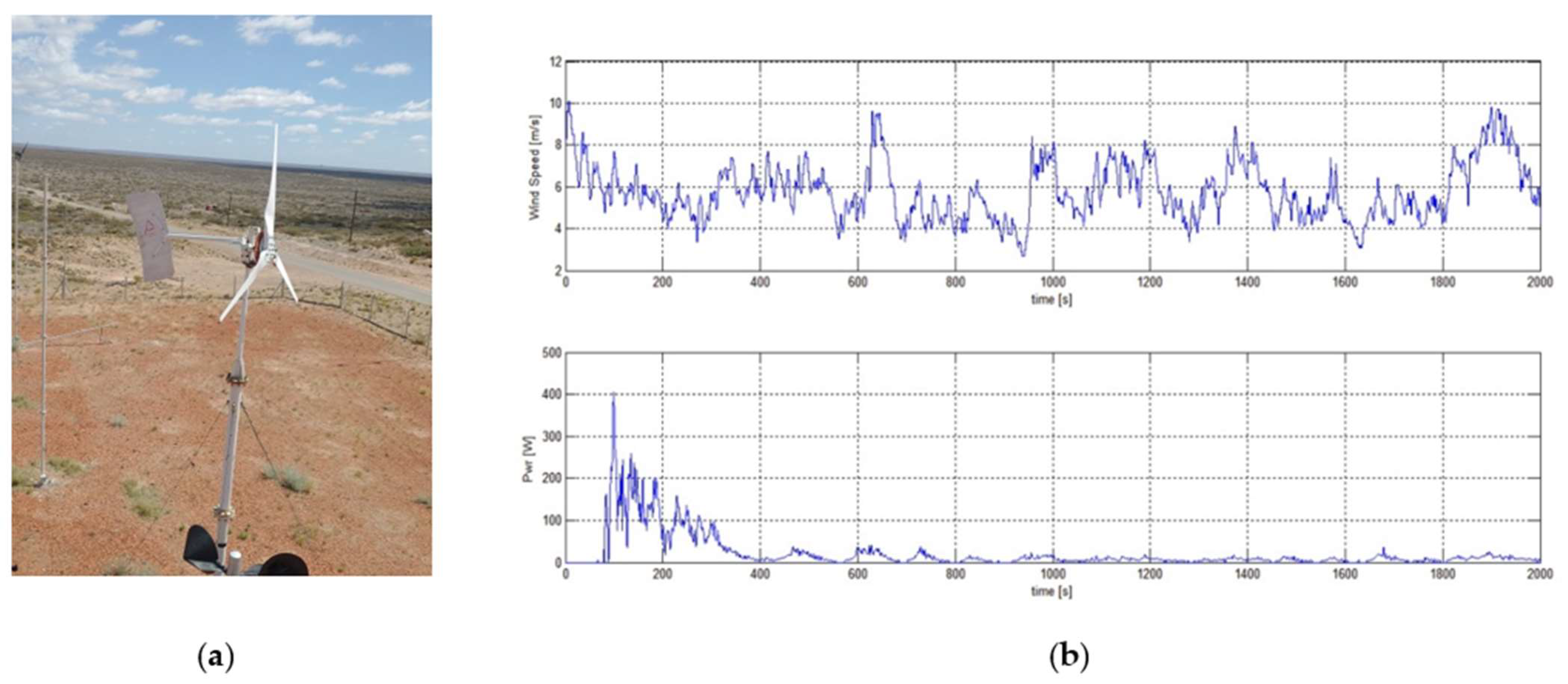
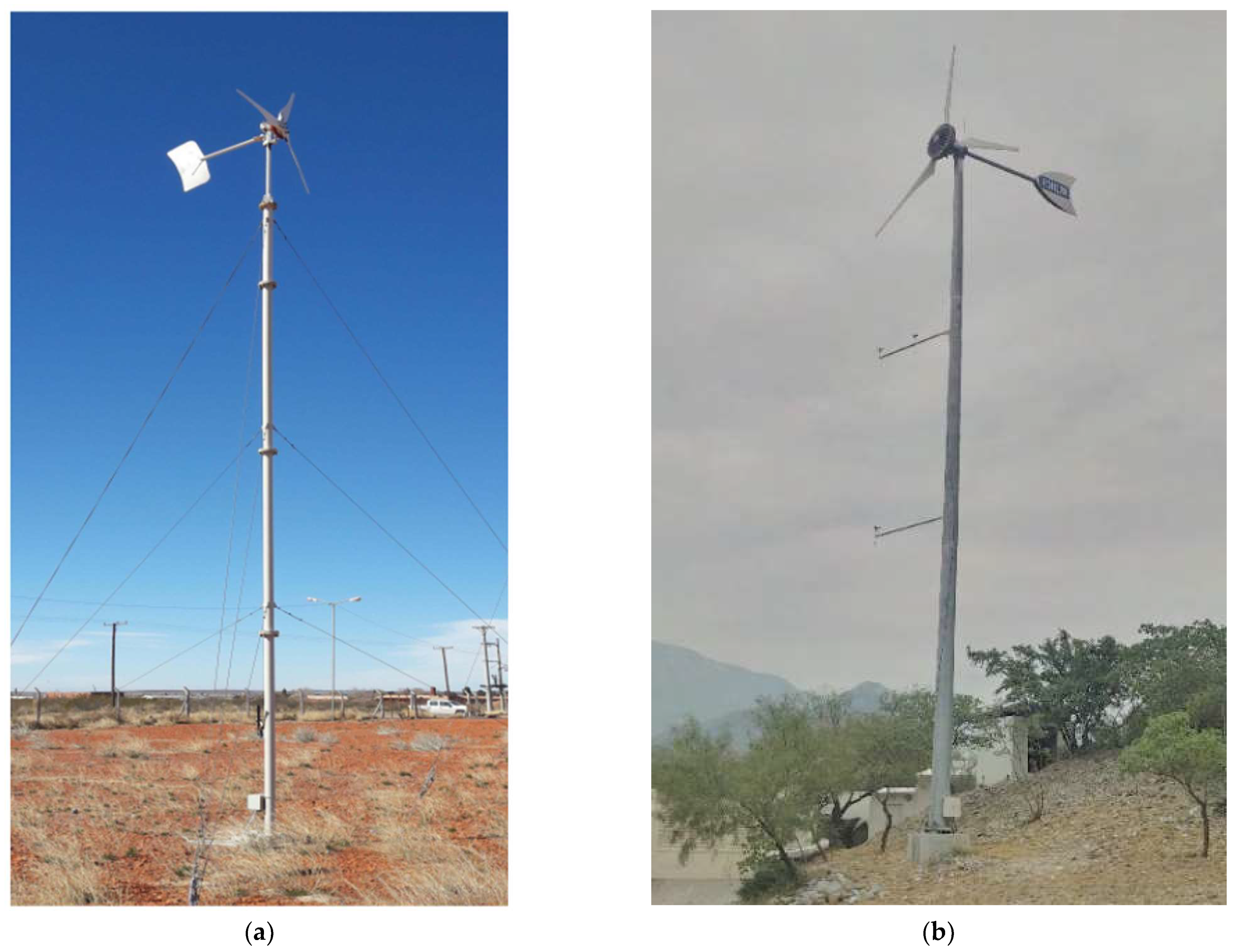
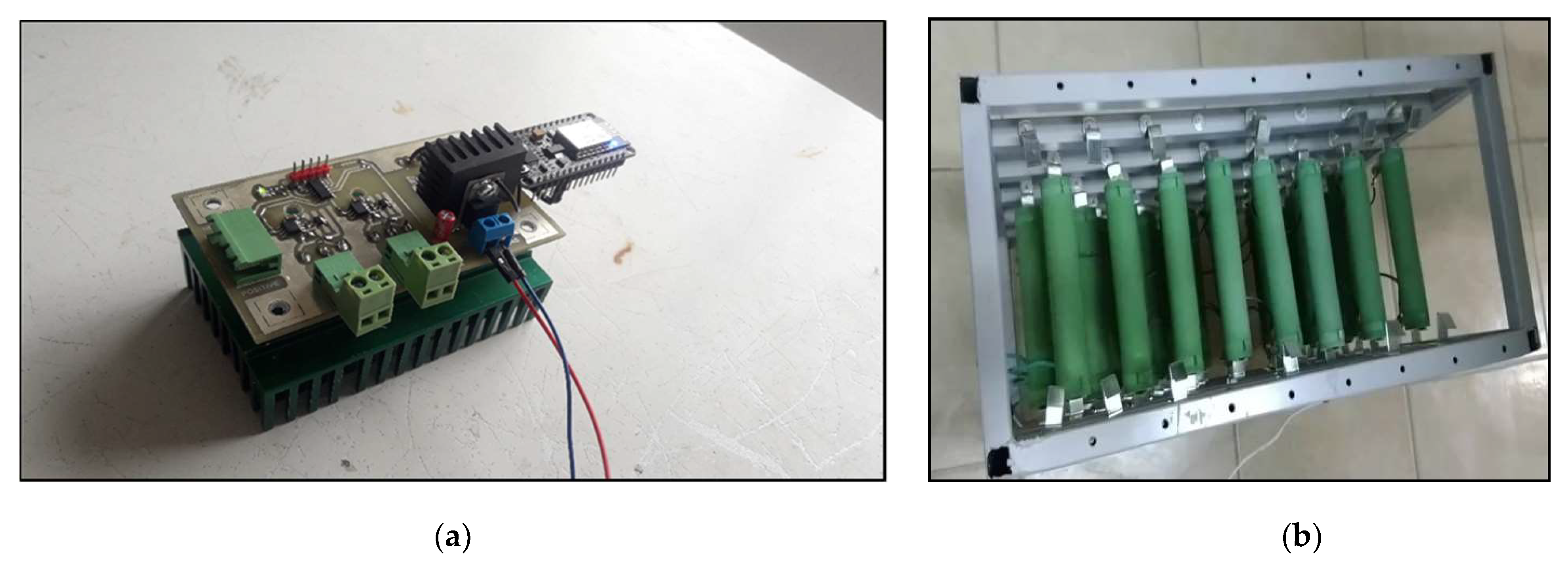
4.2. Experimental Prototype and Field Evaluation

In Figure 18, images of the experimental prototype with the deployed dump load are shown.
The test system was comprised of a bank of 32 resistors of 25 ohms/100 W each, configured to obtain 50 ohms with the possibility of dissipating up to 3200 W. The wind turbine used was a horizontal axis wind turbine with a six-pole PMSG generator, 1000 W nominal power, with nominal VDC 300 V at 350 rpm, for 12 m/s wind. As shown in Figure 14 above, the generator output was rectified and injected into a standard commercial solar PV grid-tie inverter from Omnik New Energy, model Omniksol 1K-TL2-M, with a nominal power of 1000 W, nominal voltage of DC 360 V and maximum of 500 V, and single-phase AC output of 220 V, 50 Hz.
Figure 19 shows the wind speed measurements with power and DC voltage over a time window longer than 30 min, where two voltage thresholds were applied for the test: the first between 200 V and 250 V for approximately 500 s, and the second between 250 V and 300 V for the remainder of the time window. The control action of the chopper can be clearly observed, managing at all times the DC voltage between the configured values, which is evidenced through the brief moments in which the current decreases to small values close to zero amperes with wind exceeding 15 m/s.
Although an MPPT was not configured and the inverter was associated with the I–V curve of solar panels, which has little to do with that of wind turbines, the instantaneous power obtained was close to the values expected to be obtained with these wind speeds, which is encouraging and suggests good adaptation of the prototype to a standard solar-type inverter.

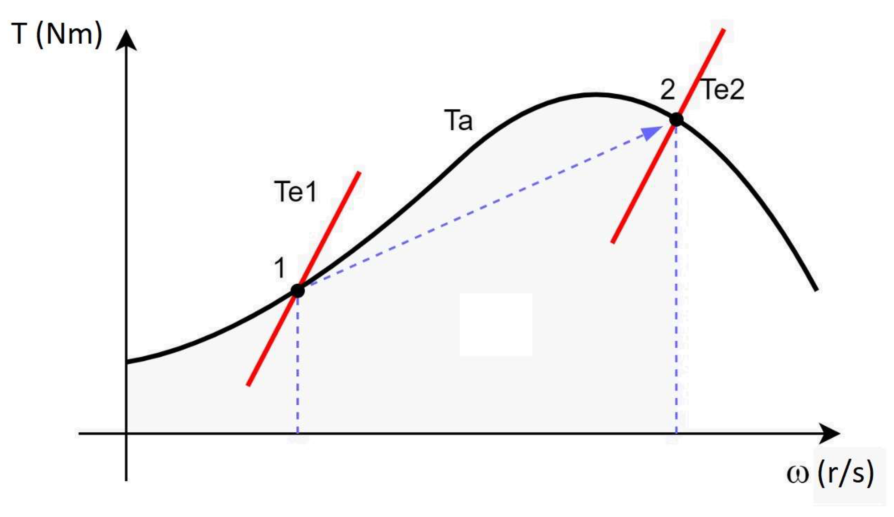
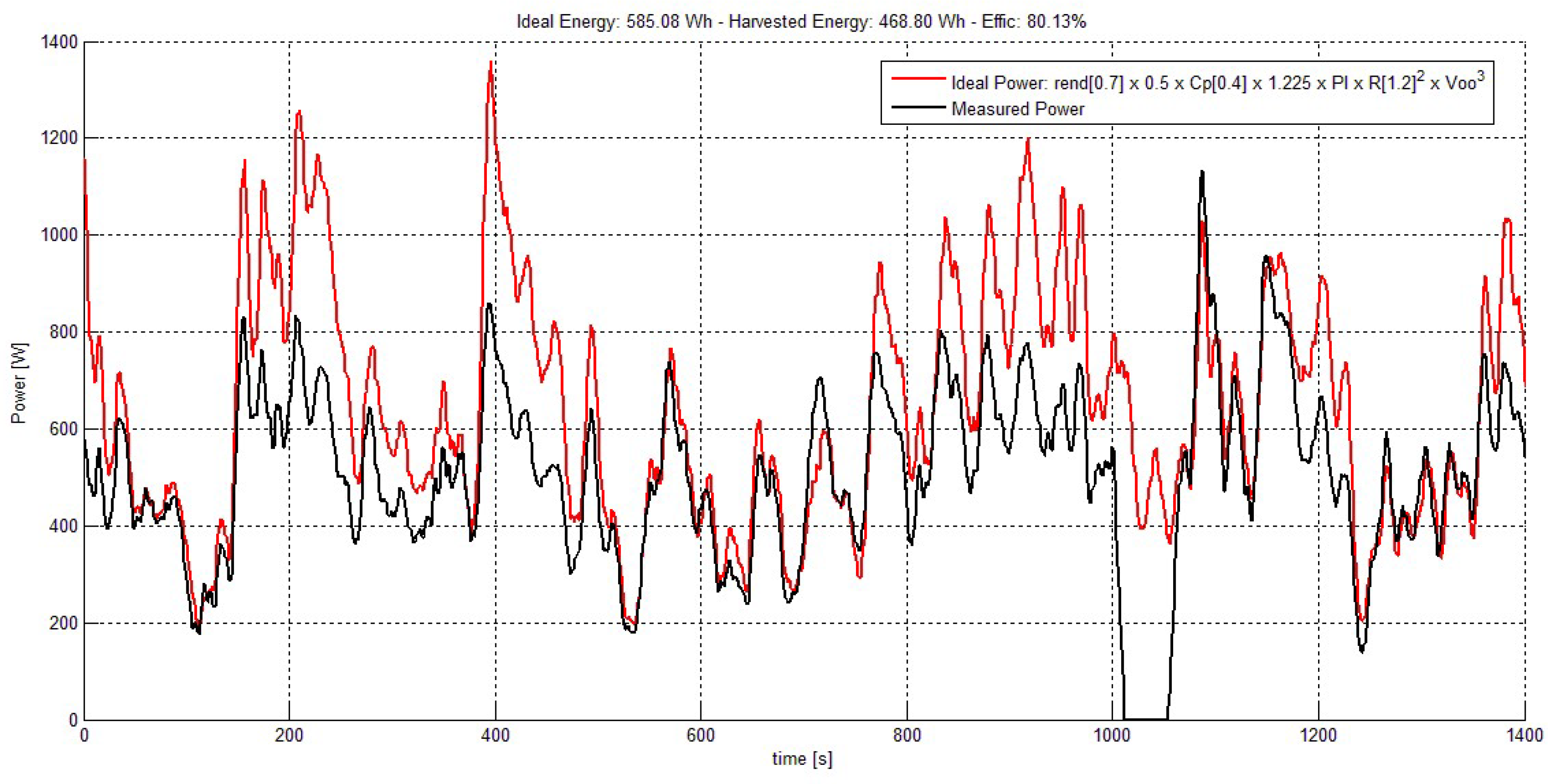
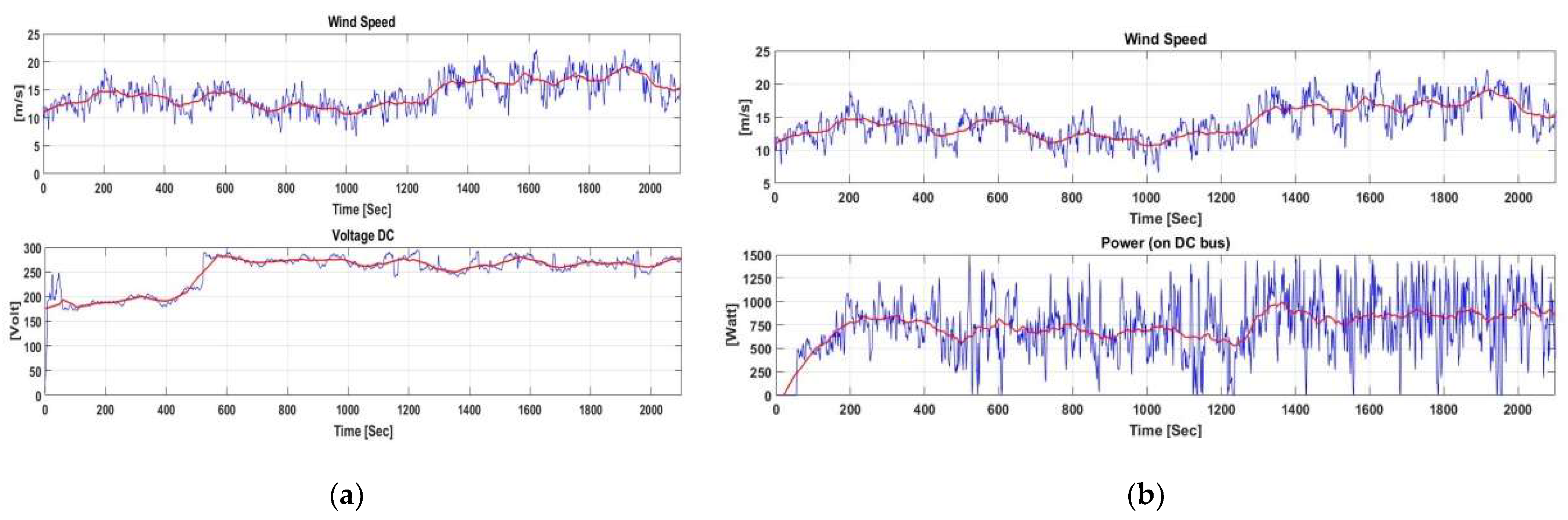
4.2.1. Analysis of Energy Performance

Figure 20, below, shows the result of field measurements of a wind system composed of a 1 kW wind turbine from Eolocal, the proposed overvoltage protection (chopper), and an inverter for solar systems from Omnik (On-grid) with a power rating slightly higher than that of the wind turbine.
It is observed that after a few minutes, although the average wind speed was above 6 m/s, the power obtained was reduced to values of a few watts, much lower than what it would have to deliver for such wind speeds. It is deduced that this was mainly due to the MPPT algorithm used by the solar inverter, which was programmed to act according to the I–V curve of a solar PV generator, and therefore was not well adapted to the operating conditions and performance curves of a wind turbine.
However, a reasonable solution to this problem is detailed in the next section.

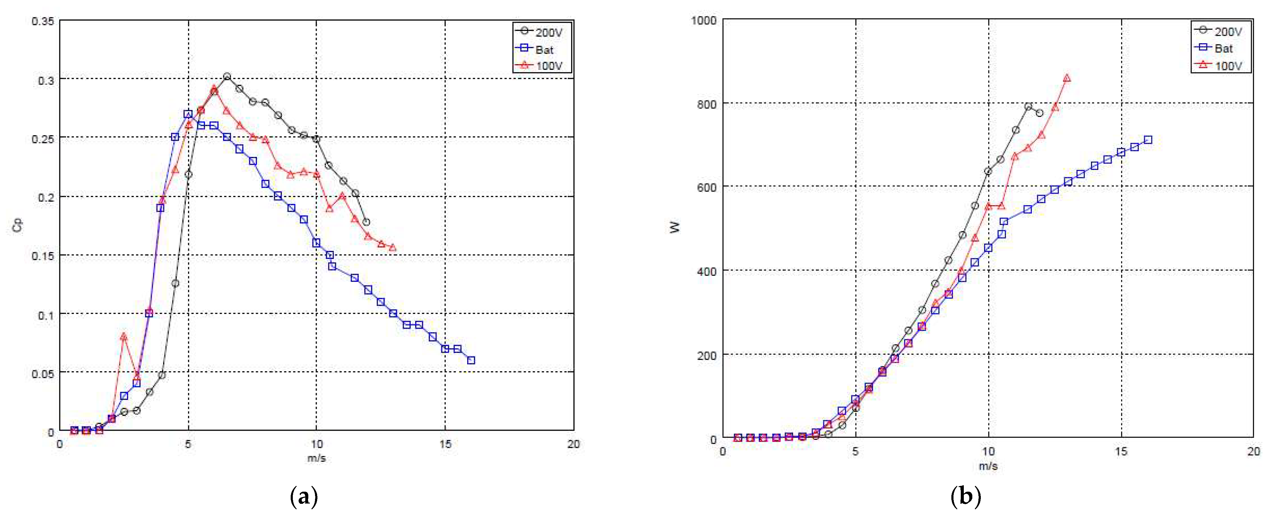
4.2.2. Proposed Energy Improvement When Using a Solar Inverter

As indicated in previous sections, given both the development of solar PV inverters at power ratings below a few tens of kW, and the fact that “standard” on-grid wind inverters are discontinued for the most part, except for the cases of proprietary technologies developed by manufacturers, adequate SWT inverters are not easily found in the market for a low-power wind project.
Given the above, and despite the differences in physical–technological principles between inverters for wind energy relative to solar PV, the cost advantage and availability of the latter created a need to try to overcome the problems shown. To this end, after studying the operation of a solar inverter with a wind generator in the field, it was concluded that the drawback lay, as shown in Figure 21, in the fact that the MPPT algorithm of the solar inverter gradually positions the wind turbine, based on its aerodynamic torque curve, at a point of equilibrium resulting in low power performance, marked as “1”. The idea was to try to bring the system, as far as possible, to a working position, marked in the figure as “2”, where its performance would be close to the MPP of the wind generator [60].
Due to the MPPT algorithm inherent in a PV inverter, the electric torque increased over time to try to maximize the power injected into the grid, but this action in a wind turbine provoked deceleration of the rotor. This slowing of the rotor had an effect on the aerodynamic performance, reducing the mechanical torque available, and as a result of this sequence the turbine remained functional at the point marked “1”, which is a stable point between the inverter and the power produced by the rotor.
To achieve the objective of better performance (point “2”, figure above), and taking advantage of the programming flexibility of the chopper, a sequence was tested, shown in Figure 22, which allowed the operation of the system in a manner similar to the energy behavior of an ideal system that does not require such a sequence to move its operational point from “1” to “2”, thus providing a viable solution to the problem that was posed, as indicated by the results in subsequent figures.
This sequence relies on resetting the inverter once the DC voltage at its input falls below a certain threshold sensed by the chopper. Depending on the available technological resources at the wind turbine site, this reset point may be programmed in a very simple way through the chopper’s interface, providing an independent but simultaneous function to the main protection function. This consists of activating the chopper when the voltage, after an initial overshoot, falls below a given value, gradually increasing its closing activity cycle until the voltage falls below a minimum, usually approximately 50 V, where the inverter continually renews its action for several minutes (>10 min), allowing the wind system to work quite close to its optimum.
The action of deactivating the PV inverter causes the wind turbine to speed up as no electric torque is applied to the rotor, which takes between 4 to 8 s depending on wind conditions and turbine characteristics. When the maximum DC voltage is reached, the chopper protects the wind turbine, diverting the energy until the inverter is available again.
Since the reset and restart of the solar inverter takes no more than approximately 40 s, the energy lost when adding these periods over time would not exceed 5% of the total that could be obtained.
Figure 23, below, shows the energy performance of the system when using the proposed strategy relative to an “ideal” one, considering a constant Cp (power coefficient) in all working regions of the wind turbine. The proposal is very conservative and favorable in this respect, as it shows measured power of more than 80% of the optimum.
On the other hand, to show the operation of a solar inverter using a “wind MPPT”, Figure 24 corresponds to a wind MPPT control, considering an optimal and constant blade tip speed ratio in the partial load region of the SWT, in which the wind speed and rotational speed are functions of the square of the current [61].
Finally, in Figure 25a, a comparison between the proposed on-grid system with solar inverter and chopper, at two different voltage limits, and an airfoil of similar technology using the same power and a battery bank (blue curve: an off-grid system) is displayed, according to field data. Here, the Cp (power coefficient) and power curves of the airfoil are shown, both as a function of wind speed, relative to the proposed system at two different voltage levels.
Figure 25b shows a comparison between the power curves of three configurations: an off-grid system (with a generator manufactured to work at 24 VDC for battery charging mode, marked in blue) compared to the on-grid proposal using the solar inverter and chopper at 200 V (marked in black) and 100 V (marked in red).
The energy improvement of the proposed system relative to the Off-Grid system can be observed at wind speeds above 6 m/s, as shown in the fundamental power curve figure. Below this wind speed the battery system would perform better, but not by more than 10% if the voltage threshold is chosen appropriately.
For a better evaluation of the results, the duration of the field measurements should be extended and the power curves should be integrated with wind occurrence distribution; under these conditions, the benefit found through the additional functionality in the chopper controller would be obvious. The user is allowed to program the best option in a simple way through its interface, depending on wind conditions and the wind turbine, at no extra cost of the system.
In conclusion, the good performance of the experimental prototype was corroborated both in the laboratory and in the field, and it remains as future work to integrate a power supply for the driver and controller from the same DC supply, and then add a crowbar short circuit for greater safety, and continue to adjust the control algorithm through more tests and trials.

5. Conclusions

Low power wind energy can satisfy the electrical demand of DC-coupled isolated systems, and can also provide it in AC-coupled systems in places where renewable resources allow it. Despite this, it is difficult to obtain necessary commercially available power converters from the market, especially controllers and inverters for devices below a few kW and even more so <1 kW. One particular reason for this is the increase in the relative costs of power electronics as the power range decreases, which discourages traditional manufacturers from continuing to provide technologies that support wind generation.
A possible solution to the above arises in adopting solar PV inverters. In principle, this does not allow for direct replacement, since, as shown in this work, there are conceptual differences in operation between PV and wind generation systems, such as the need in the latter for the inclusion of power electronics capable of protecting the generation system as a whole, both mechanically (wind turbine) and electrically (inverter).
In order to validate the results of this review, a controller (chopper) was proposed, developed and tested. The first test results showed that, besides meeting the safety objectives, it contributed to a large extent to ensure that a wind turbine with a solar PV inverter delivered energy performance similar to or even better than other alternatives, such as an isolated battery-storage version. On one hand, it brings together flexibility in programming through a user interface that allows for simple adaptation between the wind conditions at the site and the wind turbine, across a wide power and voltage range. On the other hand, it adds an interesting technological feature that allows for the varying of the speed of action in the PWM activity cycle, which would contribute to reduced maintenance and therefore increase the useful life of the wind turbine.
It remains as future work to continue evaluating this proposal and comparing its performance with other wind turbine and solar inverter technologies, in order to ratify the development as valid according to the technological needs and costs that exist today, and in comparison to other generation options.

Author Contributions

Conceptualization, L.A., R.B. and T.K.; methodology, J.d.l.C., L.A. and T.K.; software, D.M. and R.B.; validation: A.E.Z., D.M., M.A. and R.B.; formal analysis: all; investigation: all; resources and data curation: A.E.Z., D.M., M.A. and R.B.; writing—original draft preparation: D.M., J.d.l.C., L.A., R.B. and T.K.; writing—review and editing: L.A., J.d.l.C. and T.K.; visualization: L.A., J.d.l.C., T.K. and R.B.; supervision: L.A., J.d.l.C. and R.B.; project administration: L.A. All authors have read and agreed to the published version of the manuscript.

Funding

This research received external funding from the REGEDIS network within the Programa Iberoamericano de Ciencia y Tecnología para el Desarrollo (CYTED) [62].

Institutional Review Board Statement

Not applicable.

Informed Consent Statement

Not applicable.

Data Availability Statement

An online public repository has been created on github. Both PCBs and microcontrollers Firmware and MATLAB scripts and raw data (csv files) used to generate the figures are hosted there: https://github.com/NDMDevel/SWTOMP_Data.git (accessed on 29 December 2021).

Acknowledgments

The authors thank CYTED for funding this work, and their colleagues in the REGEDIS Network, in particular Rafael Oliva (precise comments and review), Luis Cano (review) and Ignacio Cruz (support).

Conflicts of Interest

The authors declare no conflict of interest.

References

  1. Wind Energy—The Facts; Earthscan: London, UK, 2009; ISBN 978184407710.
  2. Bloomberg and SEforALL, 2020. State of the Global Mini-Grids Market Report. 2020. Available online: https://www.seforall.org/system/files/2020-06/MGP-2020-SEforALL.pdf (accessed on 3 July 2021).
  3. Small Wind Turbines Optimization and Market Promotion Project Web Page. Available online: http://swtomp.ciemat.es/ (accessed on 29 December 2021).
  4. 2013 Small Wind World Report Update; WWEA: Bonn, Germany, 2013.
  5. Arribas, L.; García Barquero, C.; Avia, F.; Zappa, A.; Duzdevich, J.P.; Amadío, M.; de la Cruz, J.; Zamora, A.; Karlson, T. Sample Survey Results. Deliverable 1.2, SWTOMP Project. Available online: http://projects.ciemat.es/documents/1349819/4792266/Deliverable+1.2+final.pdf/26b9b1e9-40a7-4214-b611-b71594e0b3d4 (accessed on 29 December 2021).
  6. Alsop, A.; Eales, A.; Sumanik-Leary, J.; Persson, J.; Ruiz Almeyda, I. Small Wind for Rural Development in the Global South: Assessing the Market. In Proceedings of the 2017 IEEE Global Humanitarian Technology Conference (GHTC), Santa Clara, CA, USA, 8–11 September 2022. [Google Scholar]
  7. Resolution 349/2021 from the Argentinian Ministry of Economy: Contracting of the Design, Construction and Initial Operation of Five Photovoltaic and Wind Generation Plants with Storage, Integrated to a Mini Grid within the PERMER Program. Available online: https://www.boletinoficial.gob.ar/detalleAviso/primera/243511/20210426 (accessed on 29 December 2021). (In Spanish).
  8. Law 27424 (2018) to Promote the Generation of Energy from Renewable Sources for Self-Consumption and the Injection of Surpluses into the Grid in Argentina. Available online: https://www.argentina.gob.ar/economia/energia/generacion-distribuida (accessed on 29 December 2021). (In Spanish).
  9. Arifujjaman, M.; Iqbal, M.T.; Quaicoe, J.E. Performance Comparison of Grid Connected Small Wind Energy Conversion Systems. Wind. Eng. 2009, 33, 1–18. [Google Scholar] [CrossRef]
  10. de Freitas, T.R.; Menegáz, P.J.; Simonetti, D.S. Rectifier topologies for permanent magnet synchronous generator on wind energy conversion systems: A review. Renew. Sustain. Energy Rev. 2016, 54, 1334–1344. [Google Scholar] [CrossRef]
  11. Arifujjaman, M.; Iqbal, M.T.; Quaicoe, J.E. Power Electronics Reliability Comparison of Grid Connected Small Wind Energy Conversion Systems. Wind. Eng. 2011, 35, 93–110. [Google Scholar] [CrossRef]
  12. Wood, D. Small Wind Turbines: Analysis, Design and Application; Springer: Berlin/Heidelberg, Germany, 2011. [Google Scholar]
  13. Bialasiewicz, J.T. Furling control for small wind turbine power regulation. In Proceedings of the 2003 IEEE International Symposium on Industrial Electronics, Rio de Janeiro, Brazil, 9–11 June 2003. [Google Scholar]
  14. Rocabert, J.; Luna, A.; Blaabjerg, F.; Rodríguez, P. Control of Power Converters in AC Microgrids. IEEE Trans. Power Electron. 2012, 27, 4734–4749. [Google Scholar] [CrossRef]
  15. Villa, L.F.L. Wind Empowerment and Open-Source Power Electronics: Creating a Fully Bottom-Up Technology Suit for Rural Electrification. 4th International Conference on Small and Medium Wind Energy, On-Line. 2020. Available online: https://www.youtube.com/watch?v=rwPP25KDQFU&list=PL9vuawmFXuGkyknlx79dwRTBClufwBlxB&index=17 (accessed on 29 December 2021).
  16. IEC 61400-2 Ed.3; Wind Turbines–Part 2: Small Wind Turbines. International Electrotechnical Commission: Geneva, Switzerland, 2013.
  17. OMNIK New Energy. User Manual OMNIKSOL-1k-TL2-M. Available online: https://www.merkasol.com/WebRoot/StoreLES/Shops/62387086/5B3C/8760/EA84/A0C7/FC53/0A0C/6D09/F34A/UserManual_OMNIK_1k_1.5k-TL2-M_EN_V1.2.pdf (accessed on 29 December 2021).
  18. Removed from Solar Industry Directory Note. Available online: https://www.enfsolar.com/omnik (accessed on 29 December 2021).
  19. OMNIK Portal Web Page. Available online: https://www.omnikportal.net/ (accessed on 29 December 2021).
  20. Wang, H.; Nayar, C.; Su, J.; Ding, M. Control and Interfacing of a Grid-Connected Small-Scale Wind Turbine Generator. IEEE Trans. Energy Convers. 2011, 26, 428–434. [Google Scholar] [CrossRef]
  21. Kassem, A.M.; Abdelaziz, A.Y. BFA optimization for voltage and frequency control of a stand-alone wind generation unit. Electr. Eng. 2015, 97, 313–325. [Google Scholar] [CrossRef]
  22. Rezkallah, M.; Sharma, S.; Chandra, A.; Singh, B. Implementation and control of small-scale hybrid standalone power generation system employing wind and solar energy. In Proceedings of the 2016 IEEE Industry Applications Society Annual Meeting, Portland, OR, USA, 2–6 October 2016; pp. 1–7. [Google Scholar] [CrossRef]
  23. Mardal, A. Power regulation oppotunities for small wind turbines. In Proceedings of the 4th International Conference on Small and Medium Wind Energy, Folkecenter, Denmark, 23–26 November 2020. [Google Scholar]
  24. Fredericks, A.F.; Devries, I.D. Design of an auto-braking regulator for a small wind generator. In Proceedings of the AFRICON 2007, Windhoek, South Africa, 26–28 September 2007; pp. 1–5. [Google Scholar] [CrossRef]
  25. Chinchilla, M. Control de un Sistema de Generación Eólica de Velocidad Variable con Generador Síncrono Multipolar de Imanes Permanentes Acoplado a Red. Ph.D. Thesis, Universidad Carlos III, Madrid, Spain, 2001. (In Spanish). [Google Scholar]
  26. Anvir, A.A.; Merabet, A.; Beguenane, R. Real-Time Control of Active and Reactive Power for Doubly Fed Induction Generator (DFIG)-Based Wind Energy Conversion System. Energies 2015, 8, 10389–10408. [Google Scholar] [CrossRef] [Green Version]
  27. Ackermann, T. Wind Power in Power Systems; John Wiley & Sons: Hoboken, NJ, USA, 2005; ISBN 0470012676. [Google Scholar]
  28. Polinder, H. Overview of and trends in wind turbine generator systems. In Proceedings of the 2011 IEEE Power and Energy Society General Meeting, Detroit, MI, USA, 24–28 July 2011. [Google Scholar]
  29. Urtasun, A.; Sanchis, P.; Martín, I.S.; López, J.; Marroyo, L. Modeling of small wind turbines based on PMSG with diode bridge for sensorless maximum power tracking. Renew. Energy 2013, 55, 138–149. [Google Scholar] [CrossRef] [Green Version]
  30. Piggott, H. How to Build a WIND TURBINE. May 2003. Available online: https://www.scoraigwind.com/pirate%20oldies/Hugh%20Piggott%20Axial-flow%20PMG%20wind%20turbine%20May%202003.pdf (accessed on 29 December 2021).
  31. Augustin, A.; Pop, F.; Jurca, C.; Oprea, M.; Chirca, S.; Breban, S.; Radulescu, M.M. Axial-flux vs. radial-flux permanent-magnet synchronous generators for micro-wind turbine application. In Proceedings of the 2013 15th European Conference on Power Electronics and Applications (EPE), Lille, France, 2–6 September 2013. [Google Scholar]
  32. Available online: https://stcharger.com.ar/ (accessed on 29 December 2021).
  33. Available online: http://www.ebhsa.com.ar/energia-renovable/alternativa-economica---wintec-1500 (accessed on 29 December 2021).
  34. Skystream 3.7 Product Technical Specifications. Available online: https://shop.solardirect.com/pdf/wind-power/skystream-specs.pdf (accessed on 29 December 2021).
  35. Available online: https://sd-windenergy.com/small-wind-turbines/sd3-3kw-wind-turbine/ (accessed on 29 December 2021).
  36. Available online: www.ennera.com (accessed on 29 December 2021).
  37. Available online: https://www.fortiswindenergy.com/montana/ (accessed on 29 December 2021).
  38. Available online: https://www.renugen.co.uk/content/medium_wind_turbine_brochures/50_030_001_C_MANUAL_windspot_3.5_y_1.5_Manual.pdf (accessed on 29 December 2021).
  39. Available online: https://www.enair.es/en/small-wind-turbines/e70pro (accessed on 29 December 2021).
  40. Available online: www.invap.com.ar (accessed on 29 December 2021).
  41. Available online: http://www.potenciaindustrial.com.mx/es/productos/turbina-eolica-colibri.html (accessed on 29 December 2021).
  42. Matsui, Y.; Sugawara, A.; Sato, S.; Takeda, T.; Ogura, K. Braking Circuit of Small Wind Turbine Using NTC Thermistor under Natural Wind Condition. In Proceedings of the 2007 7th International Conference on Power Electronics and Drive Systems, Bangkok, Thailand, 27–30 November 2007; pp. 910–915. [Google Scholar] [CrossRef]
  43. Sugawara, A.; Yamamoto, K.; Yoshimi, T.; Sato, S.; Tsurumaki, A.; Ito, T. Research for Electric Brake Using NTC Thermistors on Micro Wind Turbine. In Proceedings of the 2006 12th International Power Electronics and Motion Control Conference, Portoroz, Slovenia, 30 August–1 September 2006; pp. 1597–1601. [Google Scholar] [CrossRef]
  44. Muljadi, E.; Forsyth, T.; Butterfield, C.P. Soft-Stall Control Versus Furling Control for Small Wind Turbine Power Regulation; Technical Report; National Renewable Energy Lab.: Golden, CO, USA, 1998. Available online: http://www.osti.gov/scitech/biblio/661575 (accessed on 29 December 2021).
  45. Hui, J.C.Y.; Bakhshai, A.; Jain, P.K. An Energy Management Scheme with Power Limit Capability and an Adaptive Maximum Power Point Tracking for Small Standalone PMSG Wind Energy Systems. IEEE Trans. Power Electron. 2015, 31, 4861–4875. [Google Scholar] [CrossRef]
  46. Dalala, Z.; Zahid, Z.U.; Lai, J. New overall control strategy for wind energy conversion systems in MPPT and stall regions. In Proceedings of the 2013 IEEE Energy Conversion Congress and Exposition, Denver, CO, USA, 15–19 September 2013; pp. 2412–2419. [Google Scholar] [CrossRef]
  47. Chen, J.; Chen, J.; Gong, C. New Overall Power Control Strategy for Variable-Speed Fixed-Pitch Wind Turbines Within the Whole Wind Velocity Range. IEEE Trans. Ind. Electron. 2013, 60, 2652–2660. [Google Scholar] [CrossRef]
  48. Lumbreras, C.; Guerrero, J.M.; Garcia, P.; Briz, F.; Reigosa, D.D. Control of a Small Wind Turbine in the High Wind. IEEE Trans. Power Electron. 2015, 31, 6980–6991. [Google Scholar] [CrossRef]
  49. Power One. Aurora Wind Box Interface. Installation and Operator’s Manual. 2009. Available online: https://alternateenergycompany.com/pdf/powerone/PowerOne_pvi-7200-wind_interface.pdf (accessed on 29 December 2021).
  50. ABB Wind Interface Web Page. Available online: https://new.abb.com/power-converters-inverters/wind-turbines/small-wind/legacy-small-wind-inverters-old/wind-interface-15-kw-25-kw (accessed on 29 December 2021).
  51. Available online: https://www.solar-electric.com/lib/wind-sun/TriStar%20MPPT%20150V%20and%20600V%20Wind%20Charging%20Control%20Info.pdf (accessed on 29 December 2021).
  52. Available online: https://www.voltsys.com/ (accessed on 29 December 2021).
  53. Available online: http://www.folkecenterevents.net/pages/5th-Small-Wind-Conference-2021.html#Speakers (accessed on 29 December 2021).
  54. Available online: https://www.solarpowerworldonline.com/2020/03/fimer-finalizes-acquisition-of-abb-solar-inverter-business/ (accessed on 29 December 2021).
  55. Available online: https://midnitesolar.com/productPhoto.php?product_ID=320&productCatName=Wind%20and%20Hydro&productCat_ID=25&sortOrder=1&act=pc (accessed on 29 December 2021).
  56. Gangneux, C. Designing Your Own Charge Controller; Wind Empowerment, Ti’éole and Wisions; 2017; Available online: https://docplayer.net/60777447-Designing-your-own-charge-controller.html (accessed on 29 December 2021).
  57. Wind Turbine Overvoltage Protection. Available online: https://s1.solacity.com/docs/Wind%20Turbine%20Overvoltage%20Protection.pdf (accessed on 29 December 2021).
  58. Catuogno, G.; Villa, L.; Alinei, J.; Catuogno, C. Open source Hardware Technology, a sustainable solution to achieve energy for all the global south. In Proceedings of the VIII International Conference on Sustainable Development (ICSD2020), New York, NY, USA, 21–22 September 2020. [Google Scholar]
  59. Villa, L. Mid-Term Report–SEPS CALL. Modula Power to the People Project. Technical Report. 2016. Available online: https://www.researchgate.net/publication/308012118_MID-TERM_REPORT_-_SEPS_CALL_MODULAR_POWER_TO_THE_PEOPLE_PROJECT_EXECUTIVE_SUMMARY (accessed on 29 December 2021). [CrossRef]
  60. Bianchi, F. Wind Turbine Control Systems; Springer: Berlin/Heidelberg, Germany, 2007. [Google Scholar]
  61. Wu, B. Power Conversion and Control of Wind Energy Systems; John Wiley and Sons: Hoboken, NJ, USA, 2011. [Google Scholar]
  62. CYTED’s Distributed Wind Generation (REGEDIS) Network Web Page. Available online: https://www.cyted.org/es/regedis (accessed on 29 December 2021).
Figure 1. Small wind turbines: 1000 W Eolocal (a) and 5 kW Aeroluz (b).
Energies 15 02082 g001
Figure 2. On- and off-grid capacity installed in the UK during 2012, as a function of SWT power range [4].
Energies 15 02082 g002
Figure 3. Grid-connected PMSG-based small wind turbine system.
Energies 15 02082 g003
Figure 4. Mechanical power curves versus rotor rotational speed as a function of wind speed.
Energies 15 02082 g004
Figure 5. Common voltage ranges on power converters, depending on usage and size [15].
Energies 15 02082 g005
Figure 6. Power control scheme in the case study, including a rectifier and a crowbar (thermo-magnet breaker).
Energies 15 02082 g006
Figure 7. PMSG axial flux double rotor: (a) prototype, (b) 3D model front, and (c) 3D model lateral.
Energies 15 02082 g007
Figure 8. Voltage signals under simulation and test conditions.
Energies 15 02082 g008
Figure 9. Simulation results under load conditions.
Energies 15 02082 g009
Figure 10. Block diagram of the electronic control system of the WINDERA wind turbine [36].
Energies 15 02082 g010
Figure 11. Example of a DC voltage curve vs. reference power on a TriStar controller [50].
Energies 15 02082 g011
Figure 12. Description of hardware in the LCA-INTEQUI system [59].
Energies 15 02082 g012
Figure 13. General Purpose Surge Protection System [57].
Energies 15 02082 g013
Figure 14. General connection diagram of the surge protection system.
Energies 15 02082 g014
Figure 15. (a) Flowchart of the PWM chopper interface, (b) response curve according to voltage and time settings.
Energies 15 02082 g015
Figure 16. (a) Circuit diagram of driver and power chopper, (b) circuit diagram of microcontroller with WiFi board and measurement.
Energies 15 02082 g016
Figure 17. Schematic of the electronic board of the experimental prototype.
Energies 15 02082 g017
Figure 18. (a) Experimental prototype of chopper with WiFi communication, (b) resistance bank (dump load).
Energies 15 02082 g018
Figure 19. (a) Wind speed (upper) and DC voltage (lower), instant (blue) and averaged (red) values, as a function of time; (b) wind speed (blue) and DC power (red) as a function of time.
Energies 15 02082 g019
Figure 20. (a) Field test layout; (b) wind speed (upper) and DC power output (lower) for performance assessment.
Energies 15 02082 g020
Figure 21. Possible working points of the system, based on the aerodynamic torque of the wind turbine relative to the electromagnetic torque imposed by the solar inverter.
Energies 15 02082 g021
Figure 22. Chopper programming sequence to improve energy performance.
Energies 15 02082 g022
Figure 23. Energy comparison between an “ideal” system and the chopper system using the additional reset functionality.
Energies 15 02082 g023
Figure 24. Comparison of the variation in the DC current relative to the quadratic function of the wind speed.
Energies 15 02082 g024
Figure 25. (a) Cp–wind speed curves comparison; (b) power curves comparison.
Energies 15 02082 g025
Table 1. Characteristics of the PMSG.
ParameterValueParameterValue
Phases3Voltage THD7.1%
Poles12Power1 kW
Phase Inductance0.0407 HPhase Voltage75 Vrms
Phase Resistance11.6 ohmTorque23.21 Nm
PM Flux1.2 T (neodymium)Angular speed400 rpm
Turns per coil355Efficiency73%
Table 2. Short list of grid-connected SWTs in the low power range and their main features.
SWTGeneratorOvervoltage/OverspeedBraking SystemControllerWebsite
MechanicElectronic
ManufacturerModelRated Power (W)Number of Pole PairsTypeVoltage (Nominal, V)FurlingCentrifugalChopper + Dump LoadMPPT (+ grid)ElectronicMechanicElectro magnetic BrakeMPPTPassive Mechanical Pitch Control Stall
ST ChargerST11006003Asynch. autofurl x x [32]
EBHWintec150018007PMG autofurl x xx [33]
XZERESSkystream3.7240021PMG xx xx x[34]
SD wind energySD33000 PMG x x [35]
ENNERAWindera S3200 PMG xxxx x [36]
Fortis Montana34009PMG48–500 x x [37]
SONKYOWINDSPOT3500 PMG xxxx xx [38]
Enair70 PRO400015PMG225 xx x x [39]
INVAPIVS4500 45008PMG450autofurl x x x x[40]
Potencia IndustrialHummingbird 5 kW (Colibrí 5 kW)5000 PMG0–450 VDC x x [41]
Publisher’s Note: MDPI stays neutral with regard to jurisdictional claims in published maps and institutional affiliations.

