Article

Static-Errorless Rotor Position Estimation Method Based on Linear Extended State Observer for IPMSM Sensorless Drives

State Key Laboratory of Advanced Electromagnetic Engineering and Technology, School of Electrical and Electronic Engineering, Huazhong University of Science and Technology, Wuhan 430074, China
*
Author to whom correspondence should be addressed.
Energies 2022, 15(5), 1943; https://doi.org/10.3390/en15051943
Submission received: 22 January 2022 / Revised: 28 February 2022 / Accepted: 4 March 2022 / Published: 7 March 2022
(This article belongs to the Special Issue Active Disturbance Rejection Control in Power Electronics)

Abstract

:
This article presents a static-errorless rotor position estimation method based on the linear extended state observer (LESO) for interior permanent magnet synchronous motor (IPMSM) drives. Two second-order LESOs are utilized to estimate the α-β axis back-EMFs. A third-order LESO is incorporated into the quadrature phase-locked loop (QPLL) to achieve a high robustness of position tracking against external disturbance. In addition, considering that the nonideal back-EMF will bring DC and harmonic fluctuation errors to the estimated position, an enhanced LESO-based QPLL with static-errorless rotor position estimation is proposed. On the one hand, the DC position esti mation error caused by the phase lag of the back-EMF estimator is analyzed and compensated. On the other hand, to suppress the position harmonic fluctuations induced from the nonsinusoidal back-EMFs, a second-order generalize integrator (SOGI) is embedded in the feedforward path of the LESO-based QPLL. The experimental results on the 1.0 kW IPMSM drive platform show that, compared to the conventional method, the proposed method can achieve better position estimation performance both in steady-state operation and in transient-state operation.

1. Introduction

In recent years, interior permanent magnet synchronous motors (IPMSMs) have been widely applied in household and industrial applications owing to the advantages of high efficiency, high torque density, and good dynamic response [1]. In the typical field-oriented control (FOC) topology of an IPMSM drive, the rotor position information is the key to the accurate control of the motor’s torque and speed. Commonly, a position sensor mounted on the shaft of the motor is adopted to measure the rotor position, which not only increases the cost and size, but also reduces the system’s reliability. Therefore, it is of great significance to develop position sensorless control techniques that enable cost-effective system design, as well as provide reliable estimation of the position for the IPMSM drives.
IPMSM sensorless control methods are commonly divided into two types according to the physics principle. The first type is the high-frequency signal injection (HFI)-based methods [2,3]. The second type is the model-based methods [4,5,6,7,8,9,10,11,12,13,14,15,16,17,18,19,20,21]. In the medium-speed and high-speed operating ranges, the model-based methods hold a dominant role among various kinds of sensorless control methods. The typical topology of model-based method comprises of two parts. The first part is a back-EMF estimator, which extracts the back-EMF from the voltage and current information. The second part is a position/speed estimator, which extracts the position and speed information from the estimated back-EMF. Currently, a large number of methods have been proposed to estimate the back-EMF, for example, the disturbance observer [4,5], the sliding-mode observer (SMO) [6,7,8], the model reference adaptive system (MRAS) [9], and the extended Kalman filter (EKF) [10] [11,12].
Recent years have witnessed great development and increasing applications of active disturbance rejection control (ADRC) theory in the motor control and power electronics fields [22,23,24]. As the core of ADRC, the extended state observer (ESO) shows great prospects in the sensorless control field of IPMSMs. The main characteristics of the ESO is that the unknown internal disturbance together with the external disturbances are considered as the total disturbance. Then, the total disturbance is formulated as an extended state, which will be estimated by the ESO [25]. As the system errors induced from the sampling error, parameter variation, and other model uncertainties are all incorporated into the total disturbance, the robustness of this observer will be remarkable. At present, dozens of studies have proven its effectiveness in states and disturbance estimation [26,27,28].
Currently, the ESO is being increasingly applied in the sensorless control field of PMSMs [13,14,15,16,17]. In [13], a linear ESO (LESO) was adopted to estimate the back-EMF of an IPMSM. In [14], a sinusoidal interference estimator was inserted into the disturbance estimation loop of the LESO to achieve accurate estimation of the back-EMF under limited bandwidth. In [15], an enhanced LADRC for a sensorless IPMSM drive was proposed. The enhanced LADRC consisted of two cascaded LESOs; one was designed to estimate the back-EMF by treating it as the external disturbance, and the other one was designed to estimate the internal disturbance such as parameter mismatch. In [16], a linear-nonlinear switching ESO was proposed to improve the convergence rate as well as maintain the estimation accuracy of the back-EMF.
Regardless of what kind of back-EMF estimator is chosen, it is necessary to extract the rotor speed and position from the estimated back-EMF at the next stage of sensorless control. The arctangent function can be used to directly calculate the position [13], and the speed is calculated from the derivative of position. However, the derivative operation will bring unexpected noise to the system. The quadrature phase-locked loop (QPLL) is a better alternative for speed/position estimation [4,6,8,14,15,16,17,18,19,20,21,22,23,24,25,26,27,28,29]. The QPLL contains a proportional-integral (PI)-type loop filter, which helps to achieve zero steady-state error in tracking the DC signal. Currently, the QPLL has been extensively utilized in IPMSM sensorless control owing to its easily tuned gains and simple structure. However, the following drawbacks still exist that limit the overall performance of the sensorless control system [30,31]:
(1)
The second-order form makes it incapable of tracking ramp speed with zero steady-state error. Therefore, the performance of the sensorless control system will suffer from noticeable degradation during accelerating or decelerating operation.
(2)
Limited closed-loop control capability when dealing with fast-varying external disturbance. The internal PI regulator will cause unexpected overshoots. Therefore, a sudden external disturbance will bring significant error to the estimated speed and position.
(3)
Unable to suppress sinusoidal disturbance. In practical applications, due to the existence of inverter nonlinearities, the estimated back-EMF will contain distinct fifth- and seventh-order harmonics [12]. Hence, the position error in the forward path of the QPLL contains sixth-order harmonic fluctuations. Consequently, the estimated position and speed will contain sixth-order harmonic fluctuations as well.
To overcome the above drawbacks of the conventional PI-type QPLL, a more efficient estimator should be adopted to replace the PI regulator in the QPLL. In fact, the ESO, with its unique advantages in handling disturbance and uncertainties, is a competitive candidate for speed and position estimation.
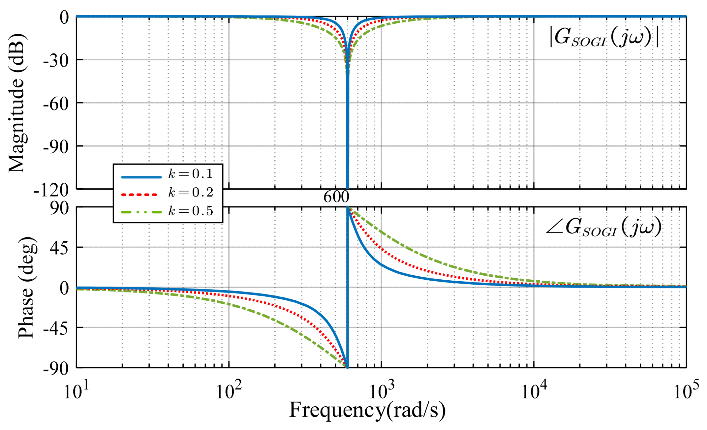
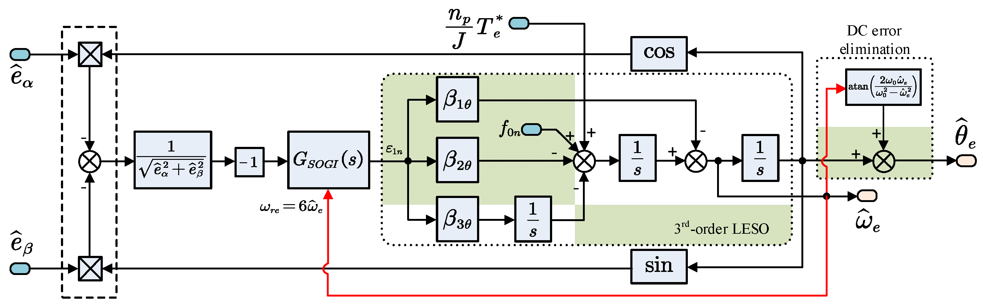
Therefore, in this article, a static-errorless position estimation method based on the LESO is proposed. Two second-order LESOs are designed to estimate the α- and β-axis back-EMFs. A third-order LESO is incorporated into the QPLL to enhance the position tracking performance and the robustness against external disturbance. To achieve static-errorless position estimation, the proposed LESO-based QPLL is improved from two aspects. On the one hand, the DC position estimation error induced from the phase lag of the back-EMF estimator is analyzed and compensated. On the other hand, to suppress the position harmonic fluctuations induced from the nonsinusoidal back-EMFs, a second-order generalize integrator (SOGI) is inserted into the feedforward path of the LESO-based QPLL.
The remaining parts of this article are organized as follows. Section 2 gives a brief description of the LESO, and the LESO-based back-EMF estimator is designed. Section 3 analyzes the existing drawbacks of the conventional QPLL, followed by the design of the LESO-based QPLL. To further diminish the position estimation error, Section 4 proposes an enhanced LESO-based QPLL. The experimental results are presented in Section 5. Finally, the conclusions are drawn in Section 6.

2. Design of the LESO-Based Back-EMF Estimator

2.1. Description of LESO

Consider the following first-order single-input-single-output (SISO) system:
x ˙ = f 0 x , t + f 1 t + b u 0
where x is the state variable, u 0 is the system input, b is the critical gain, f 0 x , t is the known disturbance, and f 1 t is the unknown disturbances. The sum of f 0 x , t and f 1 t denotes the total disturbance.
By extending the total disturbance as a new state, i.e., x 1 = x , x 2 = f 1 , the original system is transformed into the following second-order system:
x ˙ 1 = x 2 + f 0 x , t + b u 0 x ˙ 2 = f ˙ 1 t
Then, the corresponding LESO for system (2) is designed as:
ε 1 = z 1 x 1 z ˙ 1 = z 2 + b u 0 + f 0 x , t β 1 ε 1 z ˙ 2 = β 2 ε 1
where z 1 is the estimation of x 1 , z 2 is the estimation of the unknown disturbance x 2 , and ε 1 is the state estimation error. β 1 and β 2 are the observer gains. According to Equations (2) and (3), the error dynamics of the LESO is obtained:
ε ¨ 1 = β 1 ε ˙ 1 β 2 ε 1 f ˙ 1 ( t )
where ε ˙ 1 and ε ¨ 1 are the first-order and second-order derivative of ε 1 , respectively. According to (3) and (4), the following transfer function can be derived:
ε 1 ( s ) x 2 ( s ) = s s 2 + β 1 s + β 2 z 2 ( s ) x 2 ( s ) = β 2 s 2 + β 1 s + β 2
In Equation (5), it can be observed that the two transfer functions are independent of the plant parameters. Thus, the LESO has high robustness against parameter variations. To facilitate gain tuning and theoretical analysis, this article adopted a scaling- and bandwidth-parameterization method proposed in [32]. Thus, the observer gains are parameterized as follows:
β 1 β 2 = 2 ω 0 ω 0 2
where ω 0 denotes the bandwidth of the LESO. A higher ω 0 helps to improve the convergence rate, but it will increase the observer’s sensitivity to noise. In practice, ω 0 should be properly designed in order to reach a tradeoff between the rapidity of convergence and the immunity to noise.

2.2. LESO-Based Back-EMF Estimator

The back-EMF model of the IPMSM is crucial for LESO design. In recent years, the equivalent back-EMF model has attracted much attention in the IPMSM sensorless control field [18]. This model inherits the concept of “active flux” [19]. In contrast to the conventional extended back-EMF model [20], this model does not need motor speed as an input, and it simplifies the mathematic model of the salient pole IPMSM into the nonsalient pole SPMSM. The equation of the equivalent back-EMF model for the IPMSM is expressed as:
u α β = R s i α β + L q i ˙ α β + e α β
with
e α β = E e q sin θ e cos θ e = ω e L d L q i d + ψ f sin θ e cos θ e
where u α β = u α u β T and i α β = i α i β T denote the stator voltage vector and the stator current vector, respectively; e α β = e α e β T denotes the equivalent back-EMF vector; E e q is the magnitude of the equivalent back-EMF; R s is the stator resistance; L d and L q are the d-q-axis inductances; ψ f is the flux linkage of permanent magnet; ω e is the electric rotor velocity; θ e is the electric rotor position.
Equation (8) can be rewritten as:
i ˙ α β = R s L q i α β + 1 L q u α β 1 L q e α β
The key to the successful application of a LESO is to reformulate the practical control plant to a cascaded integral plant and give out the definition of disturbance [22]. In Equation (9), the system input, the known disturbance, and the unknown disturbance are defined, respectively, as:
b 0 u = u α β / L q f 0 = R s i α β / L q f 1 = e α β / L q
Then, the corresponding LESO for system (9) can be designed to estimate the states and the unknown disturbance:
ε 1 = z 1 i α β z ˙ 1 = z 2 + u / L q + f 0 β 1 ε 1 z ˙ 2 = β 2 ε 1
where z 1 = z 1 α z 1 β T denotes the estimated stator current; z 2 = z 2 α z 2 β T denotes the estimated unknown disturbance; ε 1 = ε 1 α ε 1 β T denotes the current estimation error; β 1 and β 2 are the observer gains, which are selected the same for the α- and β-axis because the equivalent back-EMF model of the IPMSM has a symmetrical structure for both axes.
When the LESO becomes stable, the estimations of stator currents and the unknown disturbances will converge. Then, the estimated equivalent back-EMF can be obtained:
e ^ α β = L q z 2

3. Design of the LESO-Based QPLL

According to Equation (8), the estimated equivalent back-EMF contains the rotor position information. By adopting a properly designed QPLL, the rotor position and speed information can be extracted from the estimated back-EMF, thereby achieving closed-loop sensorless control of the IPMSM.

3.1. Conventional QPLL

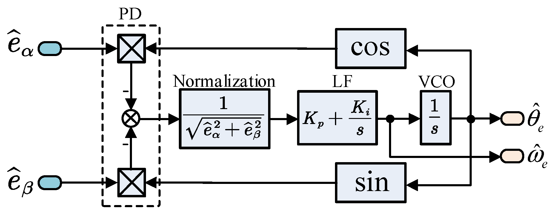
The typical structure of a conventional QPLL is shown in Figure 1. It consists of three parts: a phase detector (PD), a PI-type loop filter (LF), and a voltage-controlled oscillator (VCO). The QPLL is designed to be a closed-loop structure, where the output phase can automatically synchronize with the input phase through closed-loop regulation. In Figure 1, a phase detector is applied to extract the input phase information from the estimated back-EMFs. However, according to Equation (8), the magnitude of the estimated back-EMF varies with the rotor speed. Thus, the QPLL will show different frequency responses at different speeds. To deal with this problem, the back-EMF normalization method is commonly adopted [29], which helps the QPLL to maintain consistent frequency response at different operation speeds.
The output of the phase detector in Figure 1 is expressed as:
ε θ = e ^ α cos θ ^ e e ^ β sin θ ^ e = E ^ e q sin θ e cos θ ^ e cos θ e sin θ ^ e = E ^ e q sin θ e θ ^ e E ^ e q θ e θ ^ e
After normalization, the transfer function of QPLL is expressed as:
G QPLL s = ω ^ e s ω e s = θ ^ e s θ e s = K p s + K i s 2 + K p s + K i
where K p and K i are the proportional and integral gain, respectively. By placing the two poles of Equation (14) at the same point on the left real axis of the complex plane, the gains can be tuned as:
K p K i = 2 σ σ 2
where σ denotes the bandwidth of the QPLL. A larger σ indicates a faster tracking rate; meanwhile, it introduces more noise to the estimation result.
With a well-tuned bandwidth, the QPLL can provide accurate estimations of position and speed during steady-state operation. However, due to the fundamental limitations of the PI regulator, it is still challenging for the conventional QPLL to provide reliable estimation during transient-state operation. For example, the QPLL cannot achieve zero estimation error when tracking ramp speed [14]. In addition, the limited anti-disturbance capability will bring unexpected overshoots to the estimation results when the system encounters fast-varying external disturbance. Therefore, to improve the overall performance of the sensorless control system, it is necessary to develop a more efficient position estimator.

3.2. Design of LESO-Based QPLL

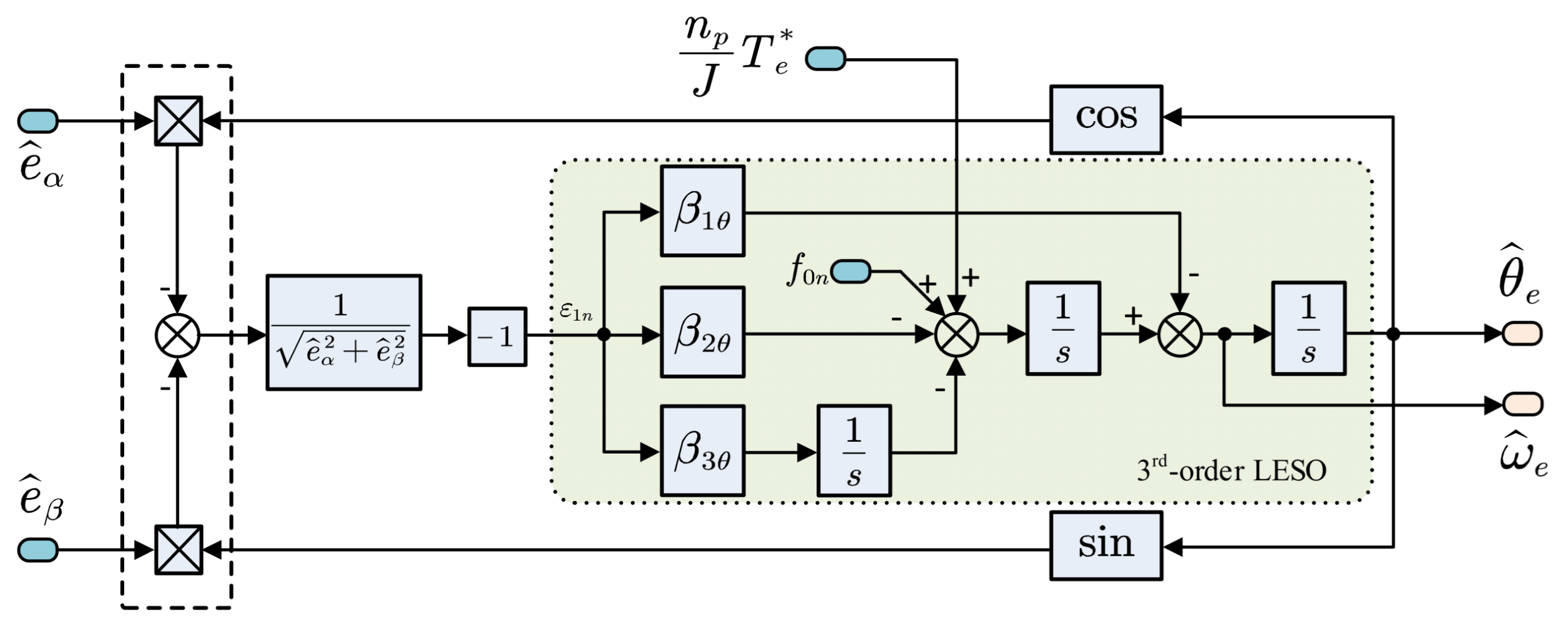
Owing to the unique disturbance estimation capability, the LESO can not only be used for back-EMF estimation, but also has the potential to facilitate the speed and position estimation. To achieve more accurate estimation under transient-state operation, the conventional QPLL is improved by replacing the PI regulator with a third-order LESO.
To construct the LESO-based QPLL, the mechanical motion dynamics of the IPMSM should be considered first:
θ ˙ e = ω e ω ˙ e = n p J T e n p J T L B J ω e
where n p is the number of pole pairs, B is the viscous friction coefficient (N·m·s/rad), J is the moment of inertia (kg·m2), T L is the load torque (N·m), and T e is the electromagnetic torque (N·m). For the employed IPMSM, T e is expressed as:
T e = 3 2 n p ψ f + L d L q i d i q
The key to the successful construction of a LESO is to reformulate the practical control plant to a cascaded integral plant and give out the definition of disturbance [22]. The known and unknown disturbance for system (16) can be defined as:
θ ˙ e = ω e ω ˙ e = f 0 θ + f 1 θ + n p J T e * f 0 θ = n p J T e T e * B J ω ^ e f 1 θ = n p J T L B J ω e ω ^ e + n θ t
where T e * is the torque reference; n θ t is the unmodeled dynamics and noise; f 0 θ and f 1 θ denote the known disturbance and the unknown disturbance, respectively; ω ^ e denotes the estimated rotor speed.
The known disturbance f 0 θ represents the disturbance that can be directly or indirectly obtained. The unknown disturbance f 1 θ represents the disturbance that cannot be acquired. Obviously, T L , ω e , and n θ t are unmeasurable in the sensorless control system. In addition, f 1 θ consists of the load torque term and the difference term between ω e and ω ^ e . Therefore, the load torque fluctuation and the sudden speed variation will both be considered in the disturbance model.
Then, a third-order LESO for system (18) can be designed by regarding the unknown disturbance f 1 θ as an extended state:
ε θ = θ ^ e θ e θ ^ ˙ e = ω ^ e β 1 θ ε θ ω ^ ˙ e = f ^ 1 θ + f 0 θ + n p J T e * β 2 θ ε θ f ^ ˙ 1 θ = β 3 θ ε θ
where θ ^ e , ω ^ e , and f ^ 1 θ are, respectively, the estimations of θ e , ω e , and f 1 θ ; ε 1 n is the position estimation error; β 1 θ , β 2 θ , and β 3 θ are the observer gains. By setting the bandwidth of the LESO to σ , the observer gains are tuned as:
β 1 θ β 2 θ β 3 θ = 3 σ 3 σ 2 σ 3
Figure 2 shows the block diagram of the proposed LESO-based QPLL. It should be noted that the error obtained from the phase detector is θ e θ ^ e . However, the estimation error of the LESO is defined as θ ^ e θ e . Therefore, a unit negative gain is inserted into the block diagram.

3.3. Comparison between the Conventional QPLL and the LESO-Based QPLL

3.3.1. Comparison of the Tracking Performance

Transforming Equation (19) into the frequency-domain, the following transfer functions can be derived:
θ ^ e s = β 1 s 2 + β 2 s + β 3 λ s θ e s + s λ s f o n s + n p J T e * s
where λ s is the characteristic polynomial of the LESO:
λ s = s 3 + β 1 θ   s 2 + β 2 θ   s + β 3 θ
Then, the position tracking error of the LESO-based QPLL can be expressed as:
G ε _ LESO s = θ ^ e s θ e s θ e s = s 3 s 3 + β 1 θ   s 2 + β 2 θ   s + β 3 θ
Meanwhile, according to (14), the position tracking error transfer function of the conventional QPLL is written as:
G ε _ QPLL s = θ ^ e s θ e s θ e s = s 2 s 2 + K p s + K i
To evaluate the tracking performance of the conventional QPLL and the LESO-based QPLL, three typical reference signals are given: the step position, the step speed, and the ramp speed. The reference signals in the frequency domain are respectively expressed as:
U m s = m s , U m s = n s 2 , U r s = r s 3
where m , n , and r are the position amplitude, the speed amplitude, and the acceleration amplitude of the reference signals, respectively. Then, by applying the final value theorem:
ε θ s s = lim t ε θ t = lim s 0 s G ε s U s
the steady-state position tracking error of the two QPLLs can be obtained, as shown in Table 1. It can be found that the position error of the conventional QPLL cannot converge to zero when tracking the ramp speed reference. The error can be reduced by increasing K i , but this will increase the overshoots during transient-state operation. As for the LESO-based QPLL, it achieves zero tracking error for the three reference signals. Therefore, it has better tracking performance than the conventional one.

3.3.2. Comparison of the Disturbance Rejection Capability

According to the mechanical motion dynamics of the IPMSM shown in Equation (16), a sudden variation in the external load torque will bring a disturbance to the rotor speed. If the rapidly changing speed goes beyond the bandwidth of the estimator, obvious speed and position estimation errors will occur. To facilitate the subsequent analysis, the torque disturbance is regarded as an acceleration disturbance d(t), the unit of which is m/s2. According to Equation (21), the influence of the acceleration disturbance on the estimated position of the LESO-based QPLL can be described by the following transfer function:
G d _ LESO s = θ ^ e s d s = s s 3 + β 1 θ   s 2 + β 2 θ   s + β 3 θ = s s + σ 3
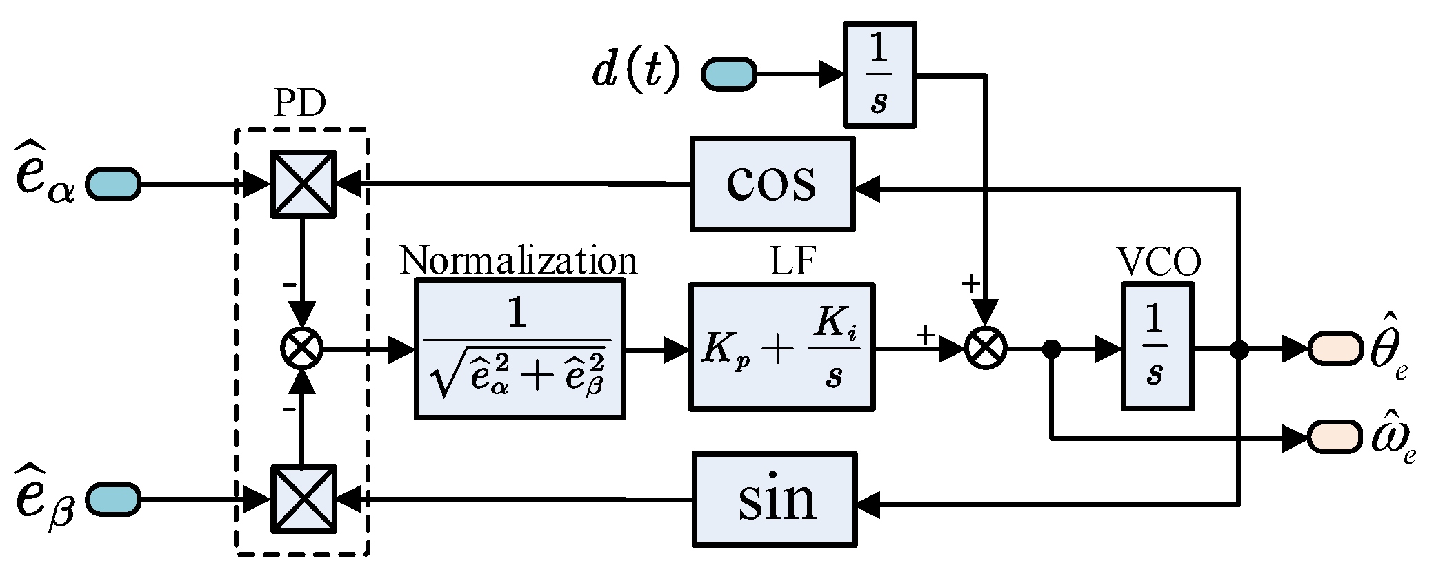
For the conventional QPLL, the disturbance is not shown in Figure 1. However, as such a disturbance is an acceleration disturbance, it can therefore be modeled into the QPLL, as shown in Figure 3.
Then, the influence of the acceleration disturbance on the estimated position of the conventional QPLL can be described by the following transfer function:
G d _ QPLL s = θ ^ e s d s = 1 s 2 + K p s + K i = 1 s + σ 2
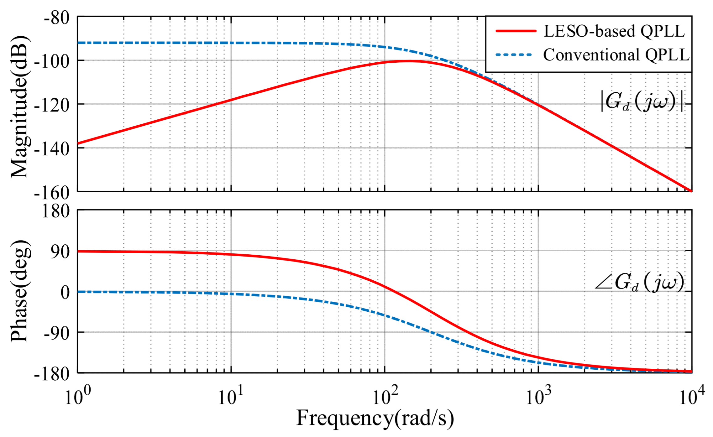
The disturbance rejection capability of the conventional QPLL and the LESO-based QPLL is compared in Figure 4, where the Bode diagrams of G d _ QPLL s and G d _ LESO s are illustrated. The bandwidth is set to σ = 200 rad/s. Thus, K p = 400 , K i = 4 × 10 4 , β 1 θ = 600 , β 2 θ = 1.2 × 10 5 , and β 3 θ = 8 × 10 6 . It can be found that the LESO-based QPLL has a better disturbance rejection capability compared to the conventional one, especially in the low-frequency range. Therefore, the LESO-based QPLL can provide a more reliable estimation of position under the influence of the external load torque disturbance.

4. Enhanced LESO-Based QPLL with Static-Errorless Position Estimation

The above-designed LESO-based QPLL estimates the rotor position and speed by tracking the phase and frequency of the estimated back-EMF. Therefore, accurate back-EMF is the precondition for reliable estimation of the position and speed. However, in a practical IPMSM sensorless control system, the estimated back-EMF is nonideal. First, due to frequency characteristics of the back-EMF estimator, there commonly exists a phase lag between the actual back-EMF and the estimated back-EMF. Secondly, due to the existence of dead-time, and the turn-on and turn-off delay of power electronic device, the inverter shows nonlinear characteristics. The voltage distortion caused by inverter nonlinearity will bring distinct fifth and seventh-order harmonic contents to the phase current, thus bringing the same order harmonics to the estimated back-EMFs [12].
The nonideal estimated back-EMF will bring DC and harmonic contents to the estimated position, thereby degrading the overall performance of the sensorless control system. To deal with such a problem, an enhanced LESO-based QPLL with static-errorless position estimation is proposed in this section.

4.1. DC Position Error Elimination

According to Section 2, the transfer function between the estimated back-EMF and the actual back-EMF can be expressed as:
e ^ α β ( s ) e α β ( s ) = β 2 s 2 + β 1 s + β 2 = ω 0 2 s + ω 0 2
It can be seen from Equation (29) that the transfer function resembles a second-order low-pass filter. Thus, the estimated back-EMF will lag behind the actual back-EMF, and the resulting estimated position will lag behind the actual position as well. According to (5), the phase lag caused by the back-EMF estimator is derived as:
Δ θ d c ( ω e ) = arctan 2 ω 0 ω e ω 0 2 ω e 2
where ω e is the frequency of the back-EMF, which is equal to the electric rotor speed. In the sensorless control system, ω e is replaced by its estimated value ω ^ e . Then, by compensating for such phase lag, the DC position error can be eliminated.

4.2. Harmonic Position Error Suppression

4.2.1. Analysis of the Harmonic Position Error

In practical applications, the voltage distortion caused by inverter nonlinearity will bring distinct harmonics to the phase current, thus bringing the same order harmonics to the estimated back-EMFs. According to [8], the estimated back-EMF considering the harmonic contents is expressed as:
e ^ α = E ^ e x sin ω e t + θ e i k = 1 n E ^ 6 k ± 1 sin 6 k ± 1 ω e t + θ 6 k ± 1 e ^ β = E ^ e x cos ω e t + θ e i + k = 1 n E ^ 6 k ± 1 cos 6 k ± 1 ω e t + θ 6 k ± 1
where E ^ e x and E ^ 6 k ± 1 represent the amplitude of the fundamental and harmonic contents; θ e i and θ 6 k ± 1 represent the corresponding initial phase.
The estimated position can be expressed as:
θ ^ e = ω ^ e t + θ ^ e i
where θ ^ e i is the initial phase of the estimated position.
Then, the position error can be obtained from the phase detector of the LESO-based QPLL. After normalization, the position error can be expressed as:
ε θ = 1 e ^ α 2 + e ^ β 2 e ^ α cos θ ^ e e ^ β sin θ ^ e = 1 e ^ α 2 + e ^ β 2 E ^ e x sin ( ω e ω ^ e ) t + ( θ e i θ ^ e i ) + k = 1 n E ^ 6 k ± 1 sin ( 1 ± 6 k ) ω e ω ^ e t + ( θ 6 k ± 1 θ ^ e i )   θ e θ ^ e + 1 e ^ α 2 + e ^ β 2 k = 1 n E ^ 6 k ± 1 sin ± 6 k ω e + ( θ 6 k ± 1 θ ^ e i )
As can be seen in Equation (33), the position error is composed of two parts. The first part is the regular term, which is used to obtain the estimated position. The second part is the (6k)th-order harmonic term resulting from the nonideal back-EMF. Particularly, the sixth-order harmonic content is the dominant content, which will cause significant fluctuation to the estimated position and further deteriorate the system’s steady-state performance.

4.2.2. Harmonic Position Error Suppression Based on SOGI

At present, various methods have been proposed to suppress the sixth-order harmonics in the estimated position, such as the adaptive linear neural (ADALINE)-network-based filter [8], the second-order generalized integrator (SOGI) [12], or the adaptive notch filter (ANF) [33]. However, these methods all focus on eliminating the harmonic contents of the estimated back-EMFs. Therefore, at least four filters should be utilized to eliminate the fifth and seventh-order harmonic contents in the α- and β-axis back-EMFs, which increases the system’s complexity and computational burden.
In fact, it can be noticed in Equation (33) that the harmonic position error induced from the nonideal back-EMF appears in the feedforward path of the LESO-based QPLL. Therefore, it is possible that the position harmonics can be directly suppressed inside the LESO-based QPLL, rather than through eliminating the harmonic back-EMFs.
In this section, a single SOGI is inserted into the LESO-based QPLL to eliminate the sixth-order harmonic content of position error. The transfer function of the SOGI is expressed as:
G SOGI ( s ) = s 2 + ω r e 2 s 2 + k ω r e s + ω r e 2
where ω r e is the resonant frequency of the SOGI. In the frequency domain, the SOGI can be regarded as a band-stop filter. The center frequency of the stopband is ω r e , and the width of the stopband is set by k . A smaller k corresponds to a smaller stopband. Figure 5 shows the Bode diagram of the SOGI, where ω r e = 600 rad/s. Obviously, there is a notch peak at ω r e . Thus, the SOGI can be utilized to suppress the selective frequency signals.
The harmonics contents in the estimated position can be adaptively suppressed by incorporating the SOGI into the feedforward path of the LESO-based QPLL, as shown in Figure 6. As the sixth-order harmonic is the dominant harmonic content, the resonant frequency of the SOGI is set to ω r e = 6 ω ^ e .
The harmonics suppression capability of the SOGI is strongly related to the accuracy of the estimated speed. In practical applications, the estimated speed may fluctuate within a small range. To maintain the harmonics suppression capability, the SOGI should have a good tolerance to the variation in ω ^ e . Thus, a large k can be adopted. However, a large k will lead to a large phase delay in the whole frequency range; thus, the system’s phase margin will reduce. Therefore, a trade-off between the harmonics suppression capability and the system’s stability should be made.

4.3. Design of the Enhanced LESO-Based QPLL

By adopting the improvements proposed in Section 4.1 and Section 4.2, the DC and the sixth-order harmonic contents of the position estimation error induced by the nonideal estimated back-EMF can be eliminated. The block diagram of the enhanced LESO-based QPLL with static-errorless position estimation is shown in Figure 7. The resonant frequency of the SOGI is updated by the estimated speed to achieve adaptive harmonic suppression. Meanwhile, the estimated speed is also used for DC error elimination. Finally, the DC and the sixth-order harmonic contents of the position error can be suppressed in a wide-speed operating range, thereby improving the steady-state performance of the IPMSM sensorless control system.

4.4. Analysis of the Enhanced LESO-Based QPLL

The open-loop transfer function and the closed-loop transfer function of the enhanced LESO-based QPLL can be obtained:
G o s = s 2 + ω r e 2 s 2 + k ω r e s + ω r e 2 s 3 + β 1 θ   s 2 + β 2 θ   s + β 3 θ s 3 = s + σ 3 s 2 + ω r e 2 s 3 s 2 + k ω r e s + ω r e 2
G c s = G o s 1 + G o s = s + σ 3 s 2 + ω r e 2 s 3 s 2 + k ω r e s + ω r e 2 + s + σ 3 s 2 + ω r e 2
The Bode diagrams of G o s and G c s are shown in Figure 8a,b, respectively. The bandwidth of the LESO is set to σ = 100 rad/s. The parameters for the SOGI are set to k = 0.1 and ω r e = [ 500 , 600 , 700 ] rad/s. It can be noticed that both G o s and G c s have a notch peak at ω r e . Therefore, any position harmonics with the frequency of ω r e can be effectively suppressed. In addition, it can be found that the phase margins of G o s under different ω r e are almost the same, and the cut-off frequencies of G c s under different ω r e are almost the same as well. Hence, the enhanced LESO-based QPLL has a consistent performance under different operating speeds.
The influence of the observer bandwidth σ on the performance of the enhanced LESO-based QPLL is also investigated. Figure 9a shows the Bode diagram of G o s under different σ , where k = 0.1 , ω r e = 600 rad/s, and σ = [ 80 , 120 , 160 ] rad/s. Figure 9b shows the closed-loop pole distribution of G c s , where σ increases from 60 rad/s to 160 rad/s. Some key metrics of the enhanced LESO-based QPLL under different σ are presented in Table 2. Obviously, as σ increases, the phase margin increases, and the dominant poles move closer to the imaginary axis. Therefore, a smaller σ is beneficial to the system’s stability and response time. However, the crossover frequency decreases as σ decreases; thus, the capability of tracking fast-varying signals decreases. In practical applications, a trade-off between the system’s stability and the tracking performance should be made.

5. Experimental Verification

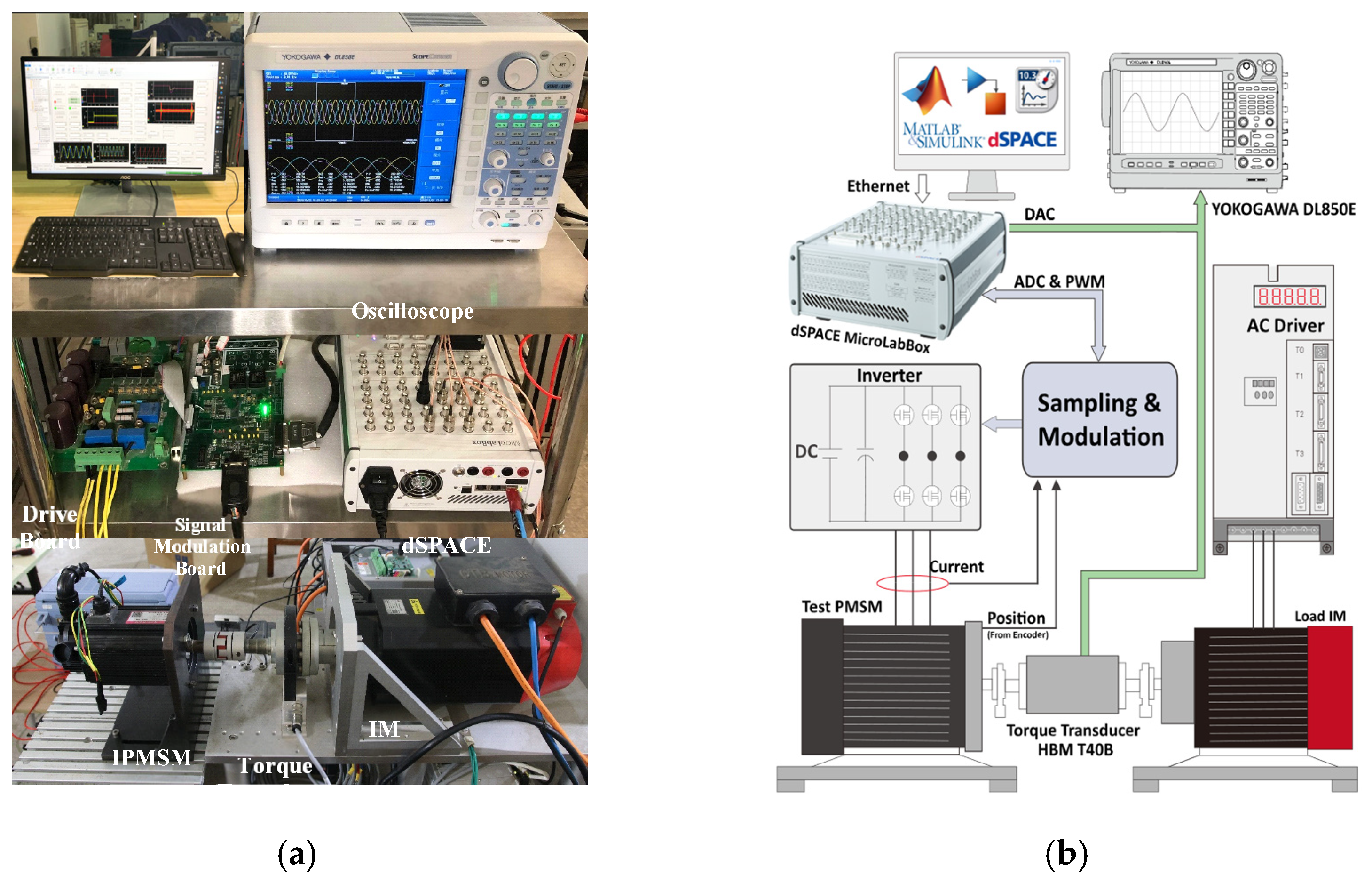
In this section, the effectiveness of the proposed IPMSM sensorless control method is verified through experimental study. The photo and the diagram of the experimental platform are demonstrated in Figure 10. During the experiment, the test IPMSM is driven by an inverter. The parameters of the IPMSM are given in Table 3. An induction motor coupled with the test IPMSM provides the load torque. The proposed control algorithm is ran on the dSPACE real-time platform. An optical encoder mounted on the shaft of the rotor is utilized to obtain the real position, which is merely for comparison purposes.
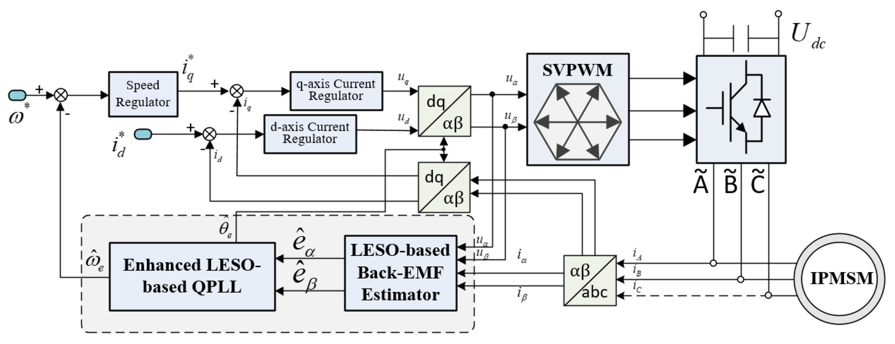
The block diagram of the IPMSM sensorless control system is shown in Figure 11. In the following experiments, the PWM switching frequency is set to 5 kHz. The DC-link voltage is set to 200 V. The deadtime of PWM is set to 4 μs. The whole algorithm is tested under the field-oriented control (FOC) structure with i d * = 0 . A simple I-f-based open-loop start-up method in [33] is utilized for start-up purposes and the system is switched to closed-loop sensorless operation at 100 rpm. The gains for speed loop PI regulators under sensorless control are set to k p n = 1.5 and k i n = 10 . The gains for d- and q-axis current loop PI regulators are set to k p d = 3.3 , k p q = 9.2 , and k i d = k i q = 705 , respectively. The bandwidth for the LESO-based back-EMF estimator is set to ω 0 = 2000 rad/s. The bandwidth for the conventional QPLL and the enhanced LESO-based QPLL are both set to σ = 150 rad/s. The parameter for the SOGI is set to k = 0.5 .

5.1. Verification of Steady-State Performation

5.1.1. Steady-State Performance of the Sensorless Control System with the Conventional QPLL

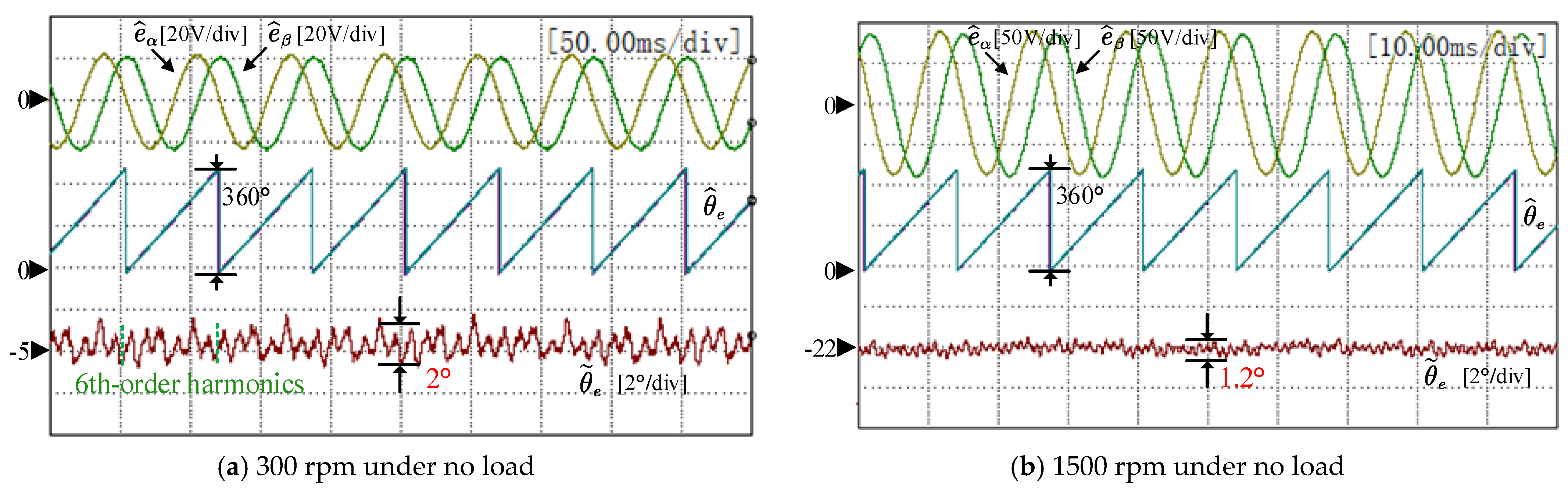
Figure 12 shows the experimental results of the estimated back-EMF, the estimated position, and the position estimation error under no load. The back-EMF is estimated by the LESO-based back-EMF estimator, and the position is obtained by the conventional QPLL. As can be seen in Figure 12a,b, the position error contains sixth-order harmonic fluctuations. The magnitude of the fluctuation at 300 rpm is around 2°, which is larger than that at 1500 rpm. This is because the magnitude of the back-EMF is proportional to the speed; thus, the voltage distortion caused by inverter nonlinearities plays a more significant role at low speed. Then, the position error harmonics is more significant at low speed.
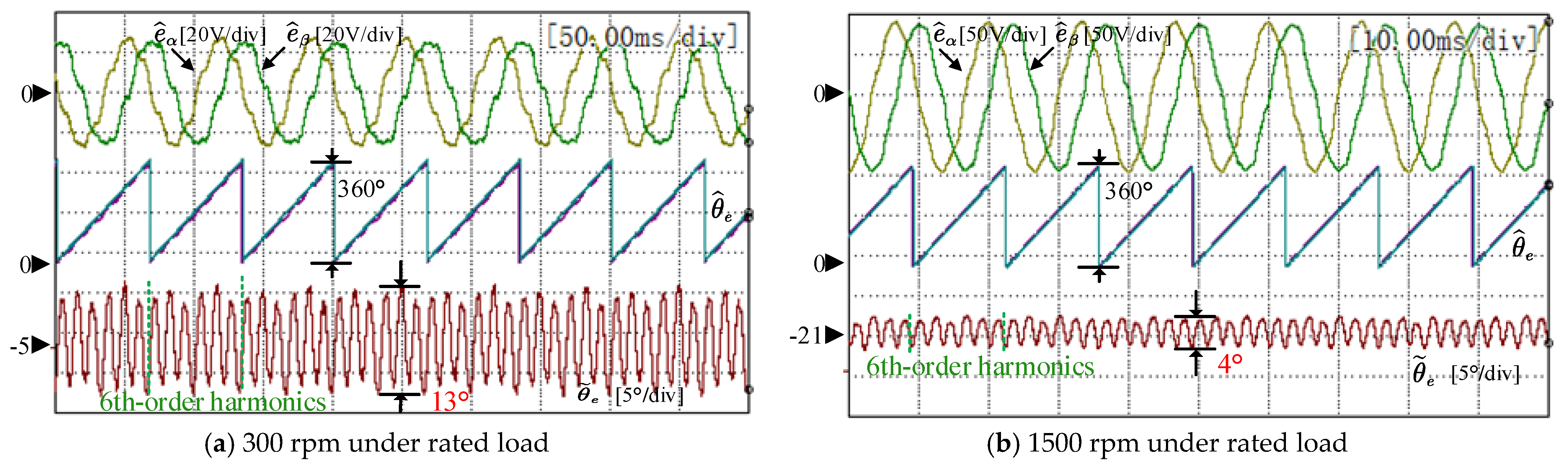
In Figure 13, the IPMSM is operating under rated load (5 N·m). It is obvious that the harmonic content of the estimated back-EMF is much more significant than that under no load. As a result, the position harmonics is also much more significant. The position error fluctuates six times in one electric position period, and the magnitude is about 6.5° at 300 rpm and 2° at 1500 rpm. In addition, it should be noted that the DC error of the position is around −5° at 300 rpm and −22° at 1500 rpm. This is because the estimated back-EMF lags behind the actual one. Then, the resulting estimated position will lag behind the actual one as well. According to above experimental results, it can be seen that the conventional QPLL is not capable of providing reliable estimation of the position in practical application.

5.1.2. Sensorless Operating at Different Speeds
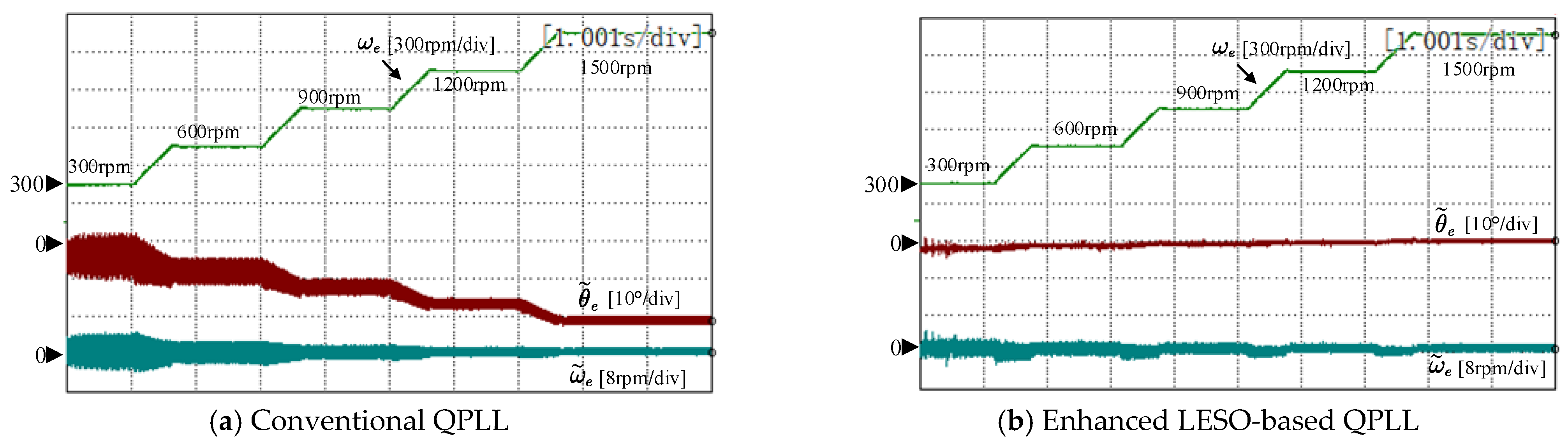
In Figure 14, the experimental results of the sensorless control system with the conventional QPLL and with the enhanced LESO-based QPLL at different speeds are presented and compared. The test machine operates under no load, and the speed command is set from 300 rpm to 1500 rpm at intervals of 300 rpm. As can be seen in Figure 14a,b for the conventional QPLL, the DC content of the position estimation error increases with the speed. However, for the enhanced LESO-based QPLL, the DC content of the position estimation error is within 2° during the wide-speed range.
In Figure 15, the experimental results of the two methods are compared under rated load. It can be seen that the fluctuations in position error and speed error using the proposed method are significantly smaller than those with the conventional method. Therefore, the effectiveness of the enhanced LESO-based QPLL in steady-state operation is verified.

5.2. Verification of Transient-State Performance
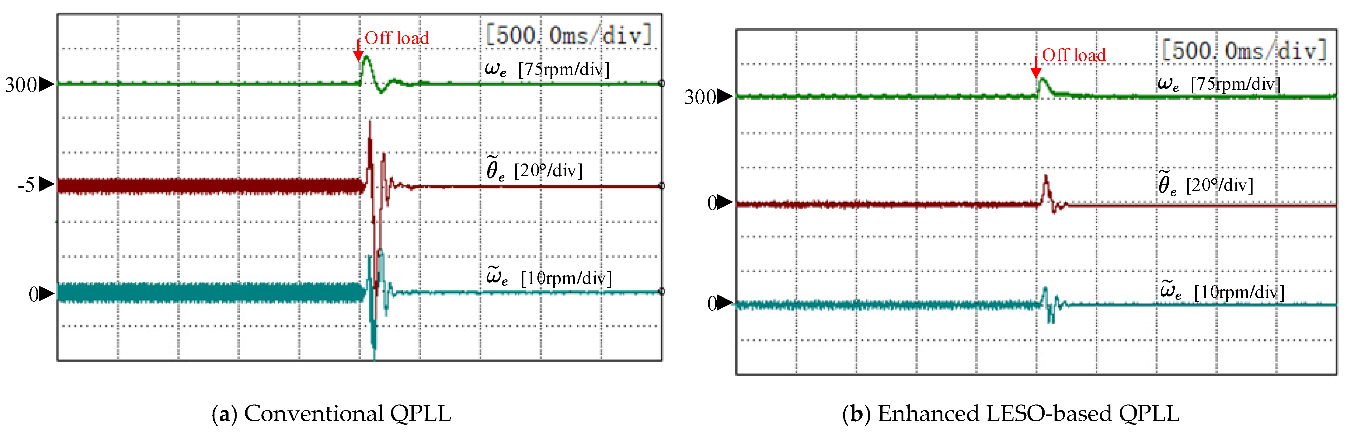
In Figure 16, the experimental results of the sensorless control system with the conventional QPLL and with the enhanced LESO-based QPLL under step load torque disturbance are compared. The command speed of the test machine is set to 300 rpm. The load machine provides a step load torque from rated load (5 N·m) to no load. During the off-load transient, the maximum position estimation error of the conventional QPLL reaches up to 75°, and the maximum speed estimation error reaches up to 20 rpm. However, the maximum position error of the enhanced LESO-based QPLL is less than 18°, and the maximum speed error is only 5 rpm.
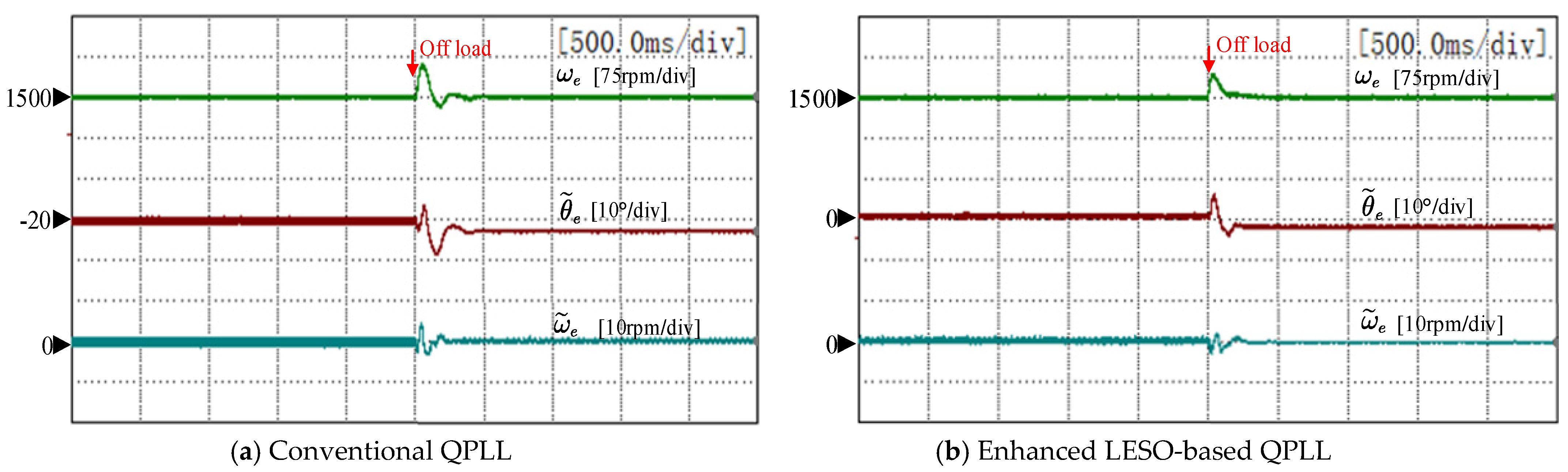
Figure 17 presents the experimental comparison of the two methods under step load torque disturbance at 1500 rpm. The maximum position error and speed error are, respectively, 8° and 5 rpm for the conventional QPLL. However, for the enhanced LESO-based QPLL, the maximum position error and speed error are, respectively, 5° and 2 rpm. According to the experimental results, it can be concluded that the proposed method has better robustness against the load torque disturbance.

5.3. Influence of Parameter Mismatches

The steady-state performance and the transient-state performance of the proposed enhanced LESO-based QPLL has been verified in above experiments. In this experiment, the influence of q-axis inductance and stator resistance mismatches on the proposed sensorless control method is investigated.
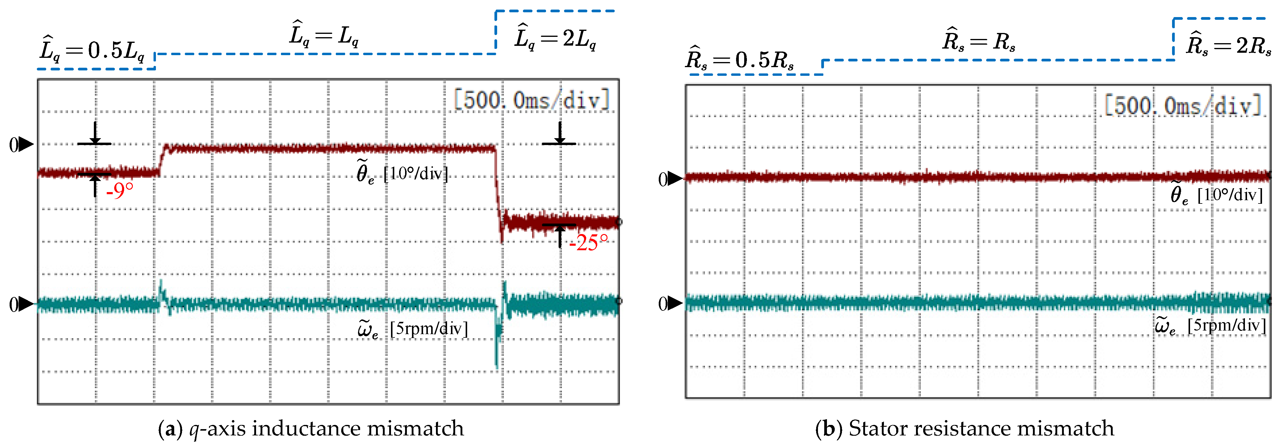
Figure 18a,b, respectively, show the experimental results with q-axis inductance mismatch and stator resistance mismatch at 300 rpm under rated load. During the experiment, the parameter changes from 50% nominal value to 200% nominal value. As can be seen in Figure 18a, the position error is about −9° when L ^ q = 0.5 L q and −25° when L ^ q = 2 L q , while the speed error is nearly the same during the whole process. In Figure 18b, the position error and speed error remain almost unchanged even though R ^ s increases from 0.5 R s to 2 R s .
Figure 19 shows the experimental results at 1500 rpm. In Figure 19a, the position error is about −12° when L ^ q = 0.5 L q and −40° when L ^ q = 2 L q , while the speed error is nearly the same during the whole process. In Figure 19b, the position error and speed error remain almost unchanged even though R ^ s increases from 0.5 R s to 2 R s .
From above results, it can be concluded that the proposed sensorless control method has strong robustness against resistance mismatch. However, q-axis inductance mismatch will bring significant errors to the estimated position, especially at high speed. In addition, as the back-EMF estimator does not require the information of d-axis inductance, this method obviously has strong robustness against d-axis inductance mismatch.

6. Conclusions

To improve the transient-state performance, as well as the steady-state performance of the IPMSM sensorless control system, this article proposes a static-errorless rotor position estimation method based on the LESO. Two second-order LESOs are utilized to estimate the α-β axis back-EMFs. A third-order LESO is incorporated into the QPLL to enhance the position tracking performance and the robustness against external disturbance. Then, considering that the nonideal back-EMF will bring DC and harmonic fluctuation errors to the estimated position, an enhanced LESO-based QPLL with static-errorless rotor position estimation is proposed. On the one hand, the DC position estimation error caused by the phase lag of the back-EMF estimator is analyzed and compensated. On the other hand, to suppress the position harmonics induced from the nonsinusoidal back-EMFs, a SOGI is inserted into the feedforward path of the LESO-based QPLL. The experimental results show that compared to the conventional method, the proposed method achieves better position estimation performance both in transient-state and in steady-state operation. During steady-state operation, the fluctuation in the estimated position using the proposed method is reduced to 1°. During the acceleration transient, the DC error of the estimated position does not exceed 2°. In addition, when encountering a large load torque disturbance at 1500 rpm, the maximum speed variation is reduced from 67 rpm to 40 rpm.
The improved sensorless control method proposed in this article is only applicable in middle- and high-speed ranges. In the low-speed range, the HFI-based method is commonly adopted. As the HFI-based method normally contains a PI-type position estimator, it will also encounter problems such as unexpected overshoots and a limited disturbance rejection capability. In our future research, we will consider introducing the proposed third-order LESO into the HFI-based method so as to improve the low-speed operation performance.

Author Contributions

Conceptualization, F.J.; Formal analysis, S.S.; Funding acquisition, K.Y.; Project administration, K.Y.; Software, F.Y.; Supervision, K.Y.; Writing—original draft, F.J.; Writing—review & editing, F.J. All authors have read and agreed to the published version of the manuscript.

Funding

This work was supported by The National Key R&D Program of China (Grant No. 2018YFB0904800), The National Natural Science Foundation of China (Grant No. 51677078), and The Science Technology and Innovation Commission of Shenzhen Municipality (Grant No. JCYJ20170307160832442).

Institutional Review Board Statement

Not applicable.

Informed Consent Statement

Not applicable.

Data Availability Statement

Not applicable.

Conflicts of Interest

The authors declare no conflict of interest.

References

  1. Lin, F.J.; Hung, Y.C.; Chen, J.M. Sensorless IPMSM drive system using saliency back-EMF-based intelligent torque observer with MTPA control. IEEE Trans. Ind. Inform. 2014, 10, 1226–1241. [Google Scholar]
  2. Wang, G.; Liu, R.; Zhao, N.; Ding, D.; Xu, D. Enhanced linear ADRC strategy for HF pulse voltage signal injection-based sensorless IPMSM drives. IEEE Trans. Power Electron. 2018, 34, 514–525. [Google Scholar] [CrossRef]
  3. Yoon, Y.D.; Sul, S.K.; Morimoto, S.; Ide, K. High-bandwidth sensorless algorithm for AC machines based on square-wave-type voltage injection. IEEE Trans. Ind. Appl. 2011, 47, 1361–1370. [Google Scholar] [CrossRef]
  4. Zhao, W.; Jiao, S.; Chen, Q.; Xu, D.; Ji, J. Sensorless control of a linear permanent-magnet motor based on an improved disturbance observer. IEEE Trans. Ind. Electron. 2018, 65, 9291–9300. [Google Scholar] [CrossRef]
  5. Park, Y.; Sul, S.K. Sensorless control method for PMSM based on frequency-adaptive disturbance observer. IEEE J. Emerg. Sel. Top. Power Electron. 2014, 2, 143–151. [Google Scholar] [CrossRef]
  6. Wang, G.; Yang, R.; Xu, D. DSP-based control of sensorless IPMSM drives for wide-speed-range operation. IEEE Trans. Ind. Electron. 2012, 60, 720–727. [Google Scholar] [CrossRef]
  7. Feng, Y.; Zheng, J.; Yu, X.; Truong, N.V. Hybrid terminal sliding-mode observer design method for a permanent-magnet synchronous motor control system. IEEE Trans. Ind. Electron. 2009, 56, 3424–3431. [Google Scholar] [CrossRef]
  8. Zhang, G.; Wang, G.; Xu, D.; Zhao, N. ADALINE-network-based PLL for position sensorless interior permanent magnet synchronous motor drives. IEEE Trans. Power Electron. 2015, 31, 1450–1460. [Google Scholar] [CrossRef]
  9. Zhao, Y.; Qiao, W.; Wu, L. Improved rotor position and speed estimators for sensorless control of interior permanent-magnet synchronous machines. IEEE J. Emerg. Sel. Top. Power Electron. 2014, 2, 627–639. [Google Scholar] [CrossRef]
  10. Quang, N.K.; Hieu, N.T.; Ha, Q.P. FPGA-based sensorless PMSM speed control using reduced-order extended Kalman filters. IEEE Trans. Ind. Electron. 2014, 61, 6574–6582. [Google Scholar] [CrossRef]
  11. Bao, D.; Pan, X.; Wang, Y.; Wang, X.; Li, K. Adaptive synchronous-frequency tracking-mode observer for the sensorless control of a surface PMSM. IEEE Trans. Ind. Appl. 2018, 54, 6460–6471. [Google Scholar] [CrossRef]
  12. Wang, G.; Ding, L.; Li, Z.; Xu, J.; Zhang, G.; Zhan, H.; Xu, D. Enhanced position observer using second-order generalized integrator for sensorless interior permanent magnet synchronous motor drives. IEEE Trans. Energy Convers. 2014, 29, 486–495. [Google Scholar]
  13. Du, B.; Wu, S.; Han, S.; Cui, S. Application of linear active disturbance rejection controller for sensorless control of internal permanent-magnet synchronous motor. IEEE Trans. Ind. Electron. 2016, 63, 3019–3027. [Google Scholar] [CrossRef]
  14. Zhang, Y.; Yin, Z.; Bai, C.; Wang, G.; Liu, J. A Rotor Position and Speed Estimation Method Using an Improved Linear Extended State Observer for IPMSM Sensorless Drives. IEEE Trans. Power Electron. 2021, 36, 14062–14073. [Google Scholar] [CrossRef]
  15. Qu, L.; Qiao, W.; Qu, L. An enhanced linear active disturbance rejection rotor position sensorless control for permanent magnet synchronous motors. IEEE Trans. Power Electron. 2019, 35, 6175–6184. [Google Scholar] [CrossRef]
  16. Jiang, F.; Yang, K.; Sun, S.; Zhang, H.; Tang, L.; Liu, A. An Improved Extended State Observer Based on Linear-Nonlinear Switching Strategy for PMSM Sensorless Control. In Proceedings of the 21st International Conference on Electrical Machines and Systems (ICEMS), Jeju, Korea, 7–10 October 2018; pp. 1696–1702. [Google Scholar]
  17. Jiang, F.; Sun, S.; Liu, A.; Xu, Y.; Li, Z.; Liu, X.; Yang, K. Robustness Improvement of Model-Based Sensorless SPMSM Drivers Based on an Adaptive Extended State Observer and an Enhanced Quadrature PLL. IEEE Trans. Power Electron. 2020, 36, 4802–4814. [Google Scholar] [CrossRef]
  18. Liu, J.; Nondahl, T.A.; Schmidt, P.B.; Royak, S.; Harbaugh, M. Rotor position estimation for synchronous machines based on equivalent EMF. IEEE Trans. Ind. Appl. 2011, 47, 1310–1318. [Google Scholar]
  19. Boldea, I.; Paicu, M.C.; Andreescu, G.D. Active flux concept for motion-sensorless unified AC drives. IEEE Trans. Power Electron. 2008, 23, 2612–2618. [Google Scholar] [CrossRef]
  20. Chen, Z.; Tomita, M.; Doki, S.; Okuma, S. An extended electromotive force model for sensorless control of interior permanent-magnet synchronous motors. IEEE Trans. Ind. Electron. 2003, 50, 288–295. [Google Scholar] [CrossRef]
  21. Lin, T.C.; Zhu, Z.Q.; Liu, J.M. Improved rotor position estimation in sensorless-controlled permanent-magnet synchronous machines having asymmetric-EMF with harmonic compensation. IEEE Trans. Ind. Electron. 2015, 62, 6131–6139. [Google Scholar] [CrossRef]
  22. Guo, B.; Bacha, S.; Alamir, M. A review on ADRC based PMSM control designs. In Proceedings of the 2017 IEEE 43rd Annual Conference of the IEEE industrial electronics society, Beijing, China, 29 October–1 November 2017; pp. 1747–1753. [Google Scholar]
  23. Liu, C.; Luo, G.; Duan, X.; Chen, Z.; Zhang, Z.; Qiu, C. Adaptive LADRC-based disturbance rejection method for electromechanical servo system. IEEE Trans. Ind. Appl. 2019, 56, 876–889. [Google Scholar] [CrossRef]
  24. Zhigang, L.; Shihua, L. A two-order active disturbance rejection control algorithm for permanent magnetic synchronous motor. In Proceedings of the Chinese Control Conference, Zhangjiajie, China, 26–31 July 2007; pp. 68–71. [Google Scholar]
  25. Han, J. From PID to active disturbance rejection control. IEEE Trans. Ind. Electron. 2009, 56, 900–906. [Google Scholar] [CrossRef]
  26. Jin, H.; Song, J.; Lan, W.; Gao, Z. On the characteristics of ADRC: A PID interpretation. Sci. China Inf. Sci. 2020, 63, 1–3. [Google Scholar] [CrossRef]
  27. Lin, P.; Wu, Z.; Fei, Z.; Sun, X.M. A Generalized PID Interpretation for High-order LADRC and Cascade LADRC for Servo Systems. IEEE Trans. Ind. Electron. 2021, 69, 5207–5214. [Google Scholar] [CrossRef]
  28. Tian, G.; Gao, Z. Frequency response analysis of active disturbance rejection based control system. In Proceedings of the IEEE International Conference on Control Applications, Singapore, 1–3 October 2007; pp. 1595–1599. [Google Scholar]
  29. Wang, G.; Li, Z.; Zhang, G.; Yu, Y.; Xu, D. Quadrature PLL-based high-order sliding-mode observer for IPMSM sensorless control with online MTPA control strategy. IEEE Trans. Energy Convers. 2012, 28, 214–224. [Google Scholar] [CrossRef]
  30. Kanjiya, P.; Khadkikar, V.; El Moursi, M.S. A novel type-1 frequency-locked loop for fast detection of frequency and phase with improved stability margins. IEEE Trans. Power Electron. 2015, 31, 2550–2561. [Google Scholar] [CrossRef]
  31. Bierhoff, M.H. A general PLL-type algorithm for speed sensorless control of electrical drives. IEEE Trans. Ind. Electron. 2017, 64, 9253–9260. [Google Scholar] [CrossRef]
  32. Gao, Z. Scaling and bandwidth-parameterization based controller tuning. Proc. Am. Control Conf. 2006, 6, 4989–4996. [Google Scholar]
  33. Wang, Z.; Lu, K.; Blaabjerg, F. A simple startup strategy based on current regulation for back-EMF-based sensorless control of PMSM. IEEE Trans. Power Electron. 2012, 27, 3817–3825. [Google Scholar] [CrossRef]
Figure 1. Block diagram of the conventional QPLL.
Energies 15 01943 g001
Figure 2. Block diagram of the LESO-based QPLL.
Energies 15 01943 g002
Figure 3. Block diagram of the conventional QPLL considering the acceleration disturbance.
Energies 15 01943 g003
Figure 4. Bode diagram of the transfer function G d _ QPLL s and G d _ LESO s ( σ = 200 rad/s).
Energies 15 01943 g004
Figure 5. Bode diagram of the G SOGI s ( ω r e = 600 rad/s).
Energies 15 01943 g005
Figure 6. Block diagram of the enhanced LESO-based QPLL.
Energies 15 01943 g006
Figure 7. Diagram of the enhanced LESO-based QPLL with static-errorless position estimation.
Energies 15 01943 g007
Figure 8. Bode diagram: (a) Bode diagram of G o s under different ω r e . (b) Bode diagram of G c s under different ω r e .
Energies 15 01943 g008
Figure 9. Bode diagram: (a) Bode diagram of G o s under different σ . (b) Closed-loop pole distribution of G c s under different σ .
Energies 15 01943 g009
Figure 10. Experimental platform: (a) Platform photo. (b) Platform diagram.
Energies 15 01943 g010
Figure 11. Block diagram of the IPMSM sensorless control system.
Energies 15 01943 g011
Figure 12. Experimental results of the estimated back-EMF, the estimated position, and the position error under no load (conventional QPLL).
Energies 15 01943 g012
Figure 13. Experimental results of the estimated back-EMF, the estimated position, and the position error under rated load (conventional QPLL).
Energies 15 01943 g013
Figure 14. Experimental results of the real speed, the position estimation error, and the speed estimation error at different operating speeds under no load.
Energies 15 01943 g014
Figure 15. Experimental results of the real speed, the position estimation error, and the speed estimation error at different operating speeds under rated load.
Energies 15 01943 g015
Figure 16. Experimental results of the real speed, the position estimation error, and the speed estimation error at 300 rpm under load torque disturbance (5 N·m → 0 N·m).
Energies 15 01943 g016
Figure 17. Experimental results of the real speed, the position estimation error, and the speed estimation error at 1500 rpm under load torque disturbance (5 N·m → 0 N·m).
Energies 15 01943 g017
Figure 18. Experimental results of the position estimation error and the speed estimation error at 300 rpm with mismatched parameters (enhanced LESO-based QPLL).
Energies 15 01943 g018
Figure 19. Experimental results of the position estimation error and the speed estimation error at 1500 rpm with mismatched parameters (enhanced LESO-based QPLL).
Energies 15 01943 g019
Table 1. Steady-state position tracking error of the two QPLLs under different reference signals.
Reference Signal ε θ s s of Conventional QPLL ε θ s s of LESO-Based QPLL
Step position00
Step speed00
Ramp speed r / K i 0
Table 2. Key metrics of the enhanced LESO-based QPLL under different σ .
BandwidthCrossover FrequencyPhase MarginDominant Poles
σ = 80 rad/s244 rad/s68°−26.8 ± 587.7j
σ = 120 rad/s365 rad/s66°−22.9 ± 583.2j
σ = 160 rad/s478 rad/s58°−18.3 ± 580.1j
Table 3. IPMSM parameters.
ParametersSymbolsValues
Rated Power P N 1.0 kW
Rated Speed ω N 1500 rpm
Rated Torque T N 5 N·m
Number of Pole Pairs n p 3
Rotor Flux Linkage ψ f 0.142 V·s
Stator Resistance R s 0.75 Ω
d-axis Inductance L d 3.5 mH
q-axis Inductance L q 9.8 mH
Load Inertia J 0.0174 kg·m2
Viscous Friction Coefficient B 0.00075 N·m·s/rad
Publisher’s Note: MDPI stays neutral with regard to jurisdictional claims in published maps and institutional affiliations.

