Article

Effect of Bipolar Plate Material on Proton Exchange Membrane Fuel Cell Performance

by
Tabbi Wilberforce
1,*,
Oluwatosin Ijaodola
2,
Ahmad Baroutaji
3,
Emmanuel Ogungbemi
2 and
Abdul Ghani Olabi
1,4
1
Mechanical Engineering and Design, School of Engineering and Applied Science, Aston University, Aston Triangle, Birmingham B4 7ET, UK
2
Institute of Engineering and Energy Technologies, University of the West of Scotland, Glasgow G72 0LH, UK
3
School of Engineering, Telford Innovation Campus, University of Wolverhampton, Telford TF2 9NT, UK
4
Department of Sustainable and Renewable Energy Engineering, University of Sharjah, Sharjah P.O. Box 27272, United Arab Emirates
*
Author to whom correspondence should be addressed.
Energies 2022, 15(5), 1886; https://doi.org/10.3390/en15051886
Submission received: 24 January 2022 / Revised: 9 February 2022 / Accepted: 28 February 2022 / Published: 3 March 2022
(This article belongs to the Special Issue New Frontiers in Proton Exchange Membrane Fuel Cell)

Abstract

:
Commercialization of proton exchange membrane fuel cells can only materials provided its performance is closely related to existing technologies useful in commercial application. Other critical parameters like the utilization of cheaper materials should be taken into account during the manufacturing of the cell. A key component in the cell that has direct correlation to the cell performance is the flow plate. The weight coupled with cost of the cell revolves around the flow plate used in the manufacturing of the cell. This study explores materials ideal for the manufacturing of fuel cells in order to improve the overall cell performance. The investigation highlights the critical impact of varying materials used in the manufacturing of flow plates for PEM fuel cells. Stainless steel (SS), aluminium (Al) and copper (Cu) were the materials considered. The flow plate designs considered were serpentine and open pore cellular foam channel. Machine learning using python for the validation of the results with Linear regression, Ridge regression and Polynomial regression algorithm was carried out. The performance of both flow field channels was compared using different bipolar plate materials. The results show that metal foam flow channels overall performance was better than serpentine flow channels with all the various bipolar plate material used and Al material outperformed Cu and SS material. There is a direct correlation in terms of the outcome of the study and literature based on the data generated experimentally. It can however be concluded that molecules of hydrogen are stable on aluminium plates compared to copper and stainless steel.

1. Introduction

One of the energy converting devices currently gaining much attention among the scientific community globally if the proton exchange membrane fuel cell. In comparison with other renewable energy sources, PEM fuel cell has several advantages such as fast start-up, zero-emission of CO2 and high-power density. As a result of the advantages of PEM fuel cells, most automobile industries are investing a lot on research and development of the technology [1,2,3,4]. Despite the accelerated progress made in the renewable energy sector, there is still a gap in terms of demand and supply due to technological advancement [5]. With the byproduct of the electrochemical reaction in fuel cells being solely water and heat, these cells are gaining much credibility as alternative to augment current global energy demand. Their higher efficiencies also make them suitable for several applications particularly in the automotive industry. Some researchers have even argued that they are the best candidates to replace fossil products being used in harnessing energy especially in the quest of producing energy that is environmentally friendly and sustainable. Though these prospects of fuel cells make them remarkable, there is still more room for improvement in terms of research as current cells have issues in terms of cost, cell life, degradation of components etc.
Fuel cells are mainly classified as a result of the kind of electrolyte that is utilised in the development of the cell. Some well know types of fuel cells are summarised in Table 1 below [6]. Molten carbonate fuel cells (MCFCs) are functional at elevated temperatures (600–700 °C). The cell is also made up of an electrolyte of molten carbonate salt [7,8]. The catalyst layer at both electrodes can be made up of non-precious metals. Solid oxide fuel cells (SOFCs) comes with an electrolyte that is solid in nature, which is commonly made up of ceramic material known as Yttria-stabilized zirconia (YSZ). They operate at a high temperature (800–1000 °C) and it can operate using a different type of fuels as well as natural gas. The SOFCs electrical is (50–65%) [9,10]. Alkaline fuel cells (AFCs) uses potassium hydroxide(KOH) as the electrolyte. The catalyst layer at both electrodes could be made up of non-precious metals. They are related to PEM fuel cells because both energy converting devices uses fuel made of hydrogen in their operational characteristics. AFCs operating temperature is between (80–150 °C) and it’s electrical efficiency is (40–70%) [11,12]. Phosphoric acid fuel cells (PAFCs) uses phosphoric acid(H₃PO₄) immerse in a porous matrix as an electrolyte which allows protons to move from the anodic to the cathodic electrode [13]. Its operation is similar to PEM fuel cells [14]. PAFCs operate between (150–200 °C) and are less efficient in electricity generation of about (37–42%) [15]. PEM fuel cells comes with a solid membrane as its electrolyte which allows proton ions to pass through it. It operating temperature is about (40–100 °C) and its efficiency is around (40–55%) [16,17].
Even though fuel cell stacks have been used in some car industries in the production of both heavy and light duty PEM fuel cell vehicles, issues like materials, weight, cost, durability and performance need improvement to make it a competitive technology in the market [18]. The bipolar plates serve as a barrier between various cells in the stack hence prevents the mixing up of the reactants within the cell. These plates operate in a way that assists in the removal of heat, thereby preventing a local buildup of thermal energy in the cell [19]. The material of the bipolar plates and flow field design affect fuel cell performance. Recently, an effort has been made to select proper bipolar plate material to boost the overall performance of PEM fuel cell.
Flow plate material is a key element that determine the weight couple with asking price of the cell. The flow plate made up of metals is widely used due to the advantages they offer like easy to manufacture, good electrical conductivity, excellent mechanical strength and low cost as shown in Figure 1. To distribute reactants across the MEA evenly, channels are created on the bipolar plate. A common types of flow plate is the serpentine flow field channel, but the main issue has to do with the dead zones within the channels which do result into the uneven distribution of reactants [20]. In recent times, researchers have shown that flow field channels affect PEM fuel cell performance. Consequently, research has proved that open-pore cellular metal foam flow channel performs better than serpentine flow channel which results in reducing the weight and uniform distribution of reactants.
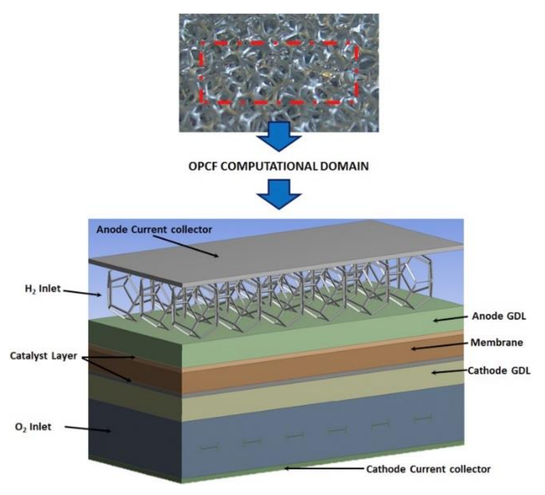
Conventional channels do encounter problem associate with pressure, temperature, humidity, reactant concentration gradients through the long flow field likely to lead to water flooding in the channels hence reducing the cell efficiency [21]. The presence of ribs affects the distribution of concentration reactants and temperature in the electrodes to the MEA plane resulting in the un-uniform distribution of reactants. A solution to this is the recent development of Open-pore cellular foam being championed as alternative to traditional flow channels. As depicted in Figure 2, these type of materials and channel design do not have ribs that could easily cause water flooding in the cell or increase pressure drop. More so, metal foams have advantages of a higher electrical conductivity when compared with non-metal current collectors, which will enhance electrical performance, but reduces the weight of the fuel cell [22,23,24,25,26]. Open pore cellular foam possesses a highly efficient thermal conductivity coupled with porosity up to 99%.

2. Materials and Methods

2.1. Experimental Set-Up

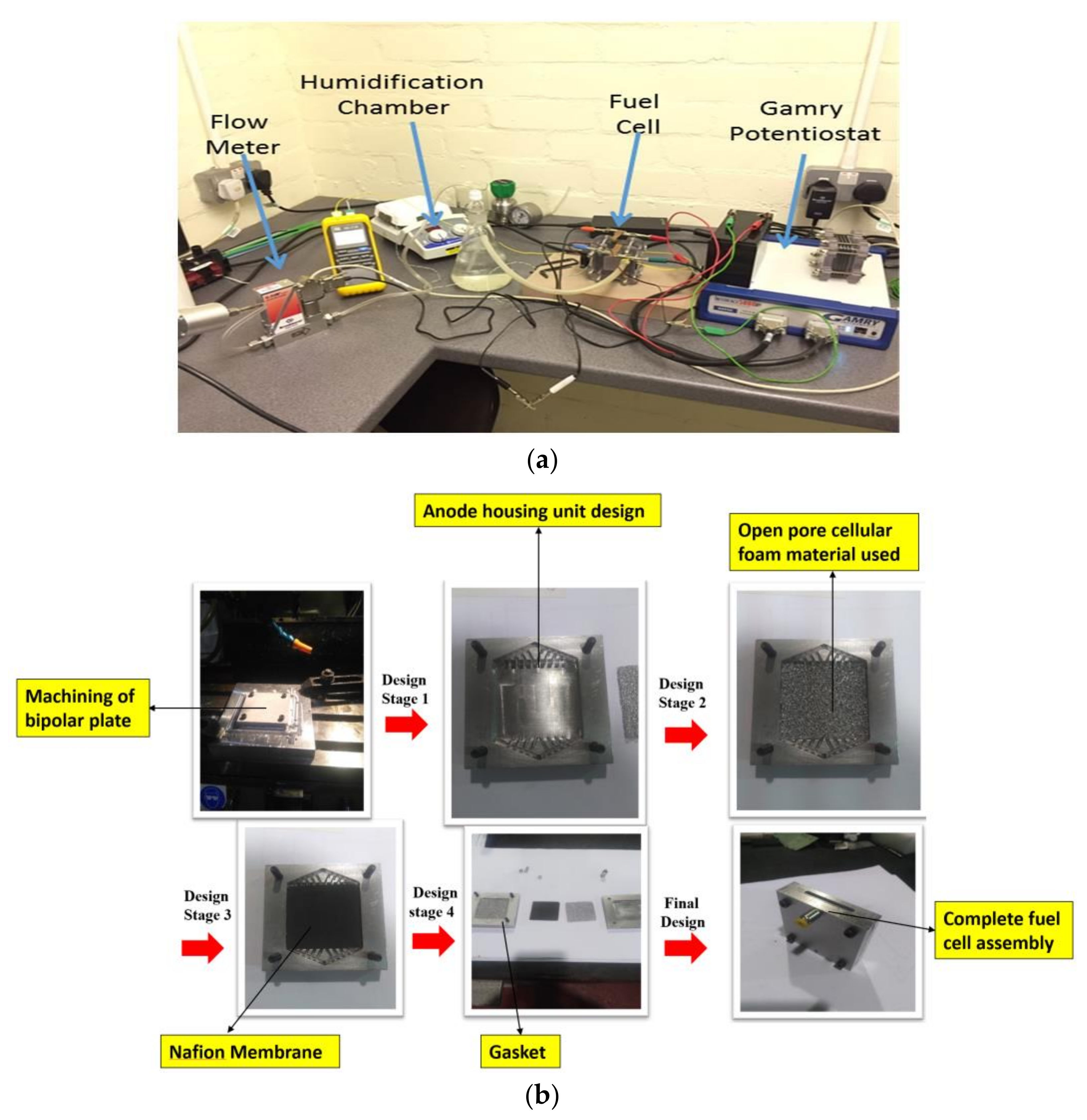
In this section, details are given about the fuel cell laboratory equipment that will be used in conducting the experimental work and the laboratory set up as shown in Figure 3. The equipment are: de-ionized water, hydrogen gas generator, humidification jar, heater, mass flow controller, temperature monitor, Gamry instrument (RS 206-3738), three different materials (Al, Cu and SS) of bipolar plates for OPCF and serpentine flow channels was used as mentioned earlier. The fuel cell component for the test was acquired from fuel cell store (United States) but all the bipolar plates used was fabricated from the University of the West of Scotland workshop. The bipolar plates dimensions for the materials was 50.6 mm × 50.6 mm × 6.32 mm. The aluminium, copper and stainless steel materials metal foam flow plates were machined to a thickness of 4.70 mm. The aluminium, copper and stainless steel bipolar plate was built to support the metal foam. The active layer for the cell was 50 × 50 mm and then platinum was used as the catalyst for the study.
A tedious task encountered during the design was to ensure that the membrane does not get damaged from the stresses of tightening during assembly. To prevent this, a gasket was positioned between the MEA and the bipolar plate to absorb stresses from the tightening of the screws during coupling of the fuel cell.
PEM fuel cell performance increases, although the membrane may begin to get dry at elevated temperature conditions due to a decline in water content in the electrolyte. If the membrane is hydrated correctly, increasing the operating temperature improves the cell performances, reduces activation losses and increases proton conductivity [27]. Also, it was observed that Al bipolar plate performed better than its counterparts due to its excellent physical adsorption with the reactants throughout the experiments. A similar experiment was performed by Tabbi et al. [28] and they reiterate the importance of reactants humidification on fuel cell overall performance.

2.2. Procedure

Before conducting the experiments, checkup was done to make sure that there were no gas leakages. The hydrogen generator tank is filled with de-ionized water, which was used in generating the fuel for the study. A tube of diameter 6.5 mm connects to the fuel cell from the hydrogen generator, which the reactant flow through it. The reactant gas was humidified by connecting a tube from the hydrogen generator to a humidifier jar and the fuel cell. This was done to improve fuel cell performance and which will humidify the membrane in the process.
The potentiostat was used to compute the fuel cell output voltages and extract current from the fuel cell as shown in Figure 3a. Relative humidity was maintained at 70%, while the reactant pressure was varied between 1.5, 2.0 and 2.5 bar.
Each single cell experiment for aluminium, copper and stainless steel serpentine bipolar plate flow field material was conducted. On the other hand, each experiment for OPCF as flow field channel with aluminium, copper and stainless steel bipolar plate materials were carried out. The data gathered was compared with existing tradition flow plates.
The reactant gas was humidified by connecting a tube from the hydrogen generator to a humidifier jar and the fuel cell. This was done to improve fuel cell performance and which will humidify the membrane in the process. The potentiostat was used to compute the fuel cell output voltages and extract current from the fuel cell. There are various reports highlighted as shown in Table 2.

3. Experimental Results

3.1. Effects of Humidification Temperature

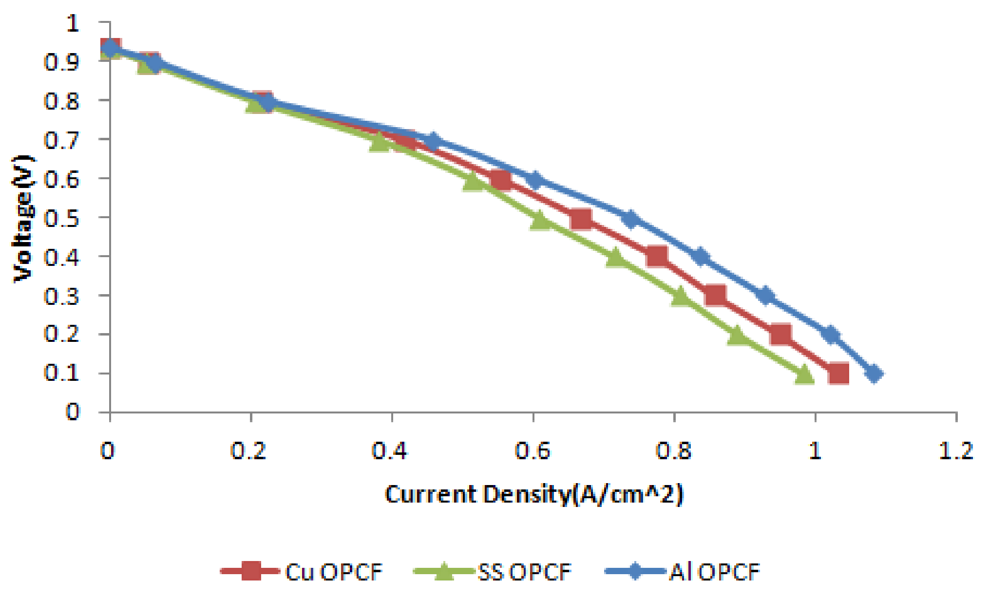
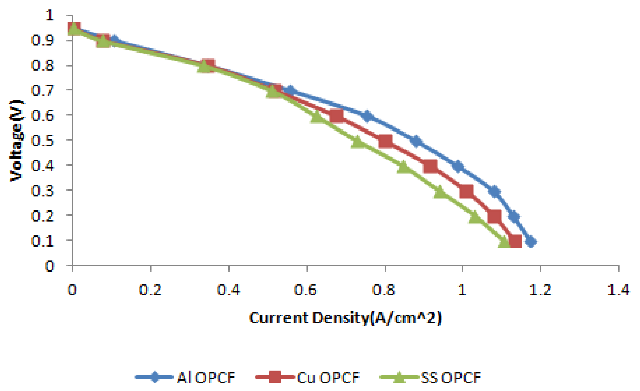
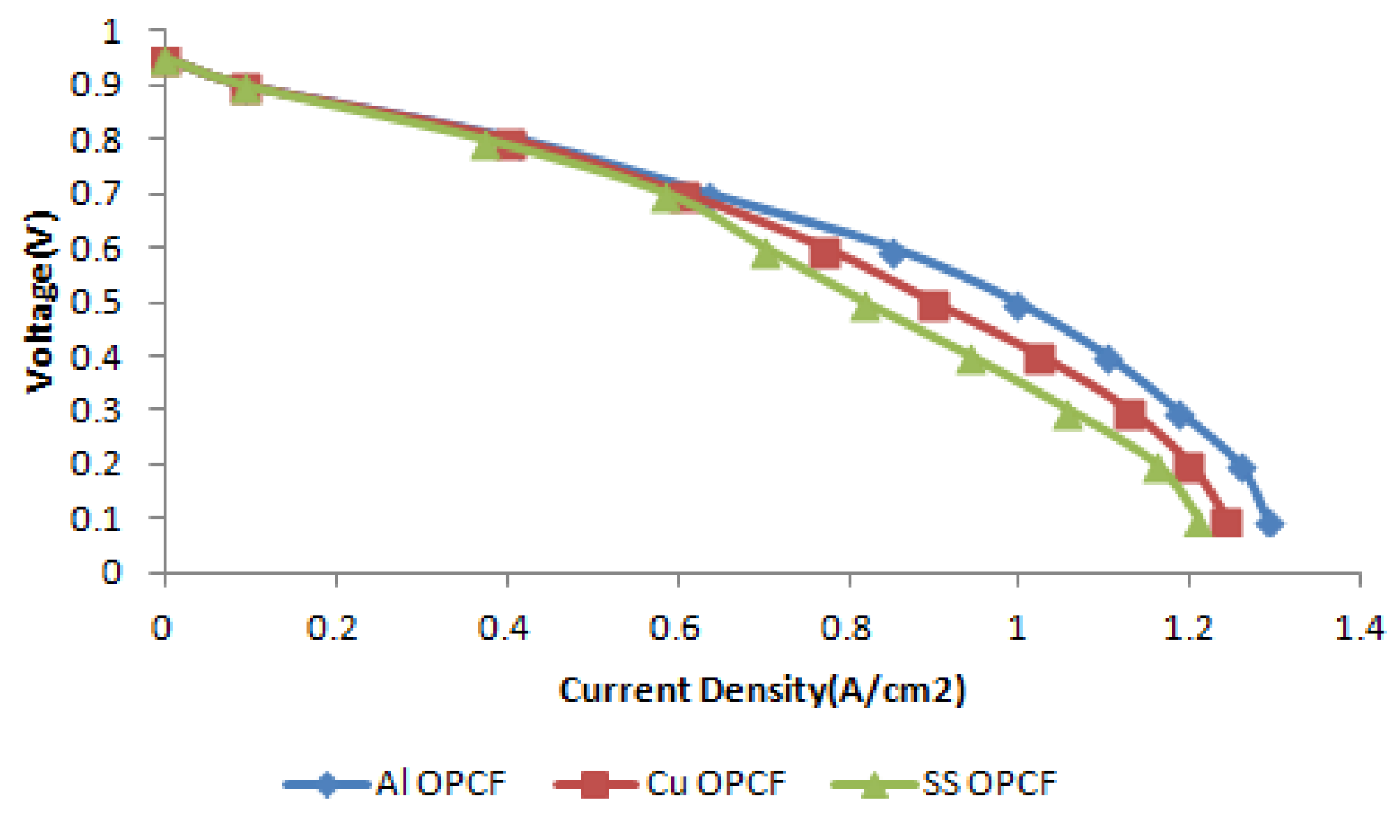
For this investigation, the concurrent impact of the operating and hydrogen humidification temperatures of the single fuel cell performance Al, Cu and SS bipolar plates material using OPCF as flow field channels was studied. The hydrogen humidification temperature conducted during the experiments were of ranges from 40 °C, 60 °C and 80 °C, while the operating temperature was kept constant at 45 °C. Figure 4 reveals the polarization curves of the single PEM fuel cell for the hydrogen humidification temperature of 40 °C. It is observed that at low temperatures, water is more in its liquid state, which may flood the GDL and catalyst layer, resulting in slower reaction kinetics and decreasing the gas diffusivity. However, when the hydrogen humidification temperature was increased to 60 °C, current density was generated and this is due to the increase of gas diffusivity as a result of mass transport improvement as shown in Figure 5. In Figure 6, the hydrogen humidification temperature was increased from 60 °C to 80 °C; the PEM fuel cell performance was more pronounced. Gas diffusivity increases as the PEM fuel cell increases, although the membrane may become to get dry at elevated temperatures due to a reduction in water content in the electrolyte. If the membrane is hydrated correctly, increasing the operating temperature improves the cell performances, reduces activation losses and increases proton conductivity [27]. Also, it was observed that aluminium bipolar plate performed well compared to its counterparts due to its excellent physical adsorption with the reactants throughout the experiments. A closely related work was performed by Tabbi et al. [28] and they reiterate the importance of reactants humidification on fuel cell overall performance.

3.2. Effect of an Operating Pressure

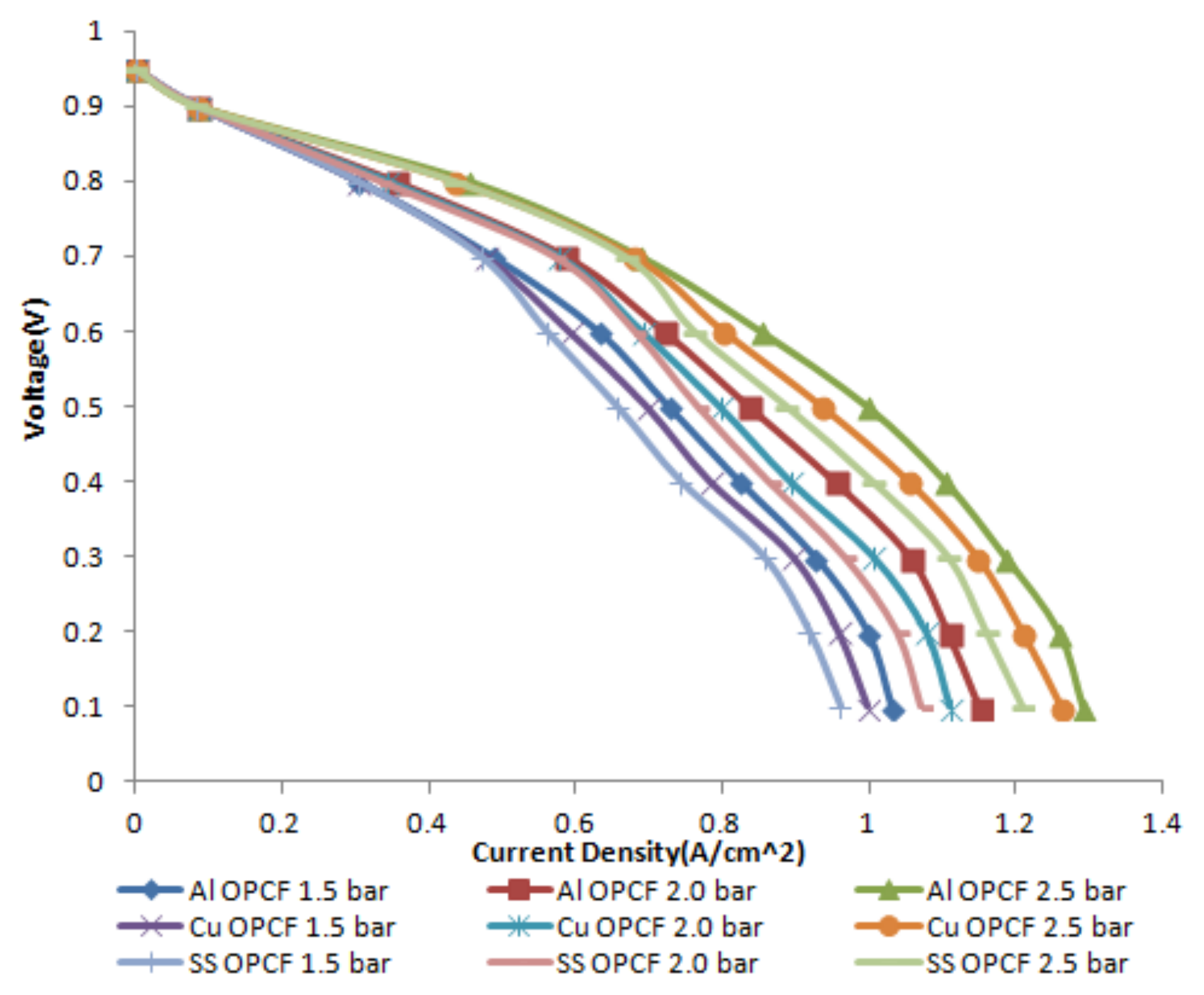
The effect of inlet hydrogen pressure 1.5, 2.0 and 2.5 bar on PEM fuel cell performance polarisation curve for each bipolar plate material for OPCF was considered as shown in Figure 7. It can be seen that the performances for each material increase steadily for all the materials as the pressure increases. The reason for this is that, as inlet hydrogen pressure in the anode increases, water contents and water activity in the membrane increases which in return reduces the ohmic overpotential. Also, the increase in water transport from anode to cathode region through hydraulic permeation [29]. It is noted that aluminium flow plate material performs well compared to copper and stainless steel material.

3.3. Hydrogen and Oxygen Consumption

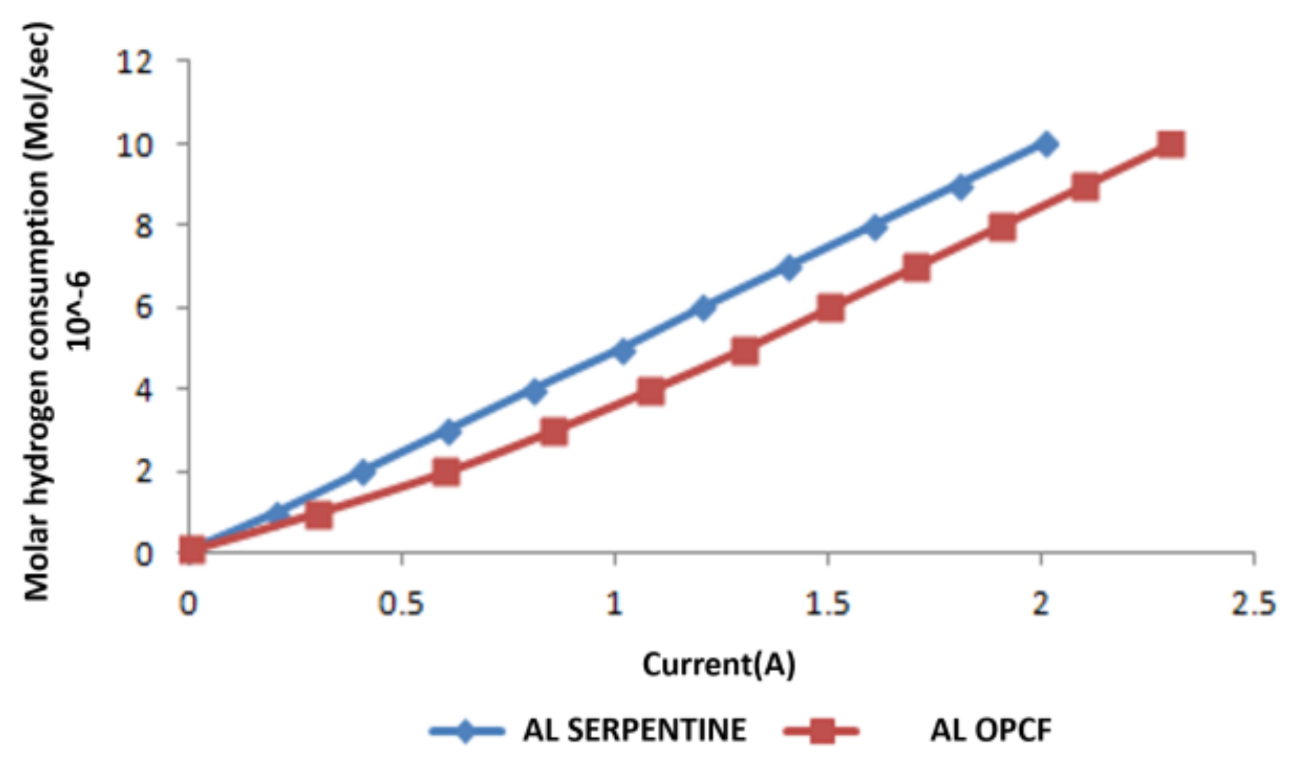
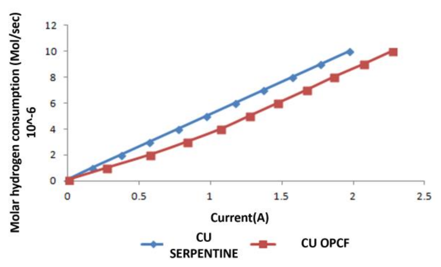
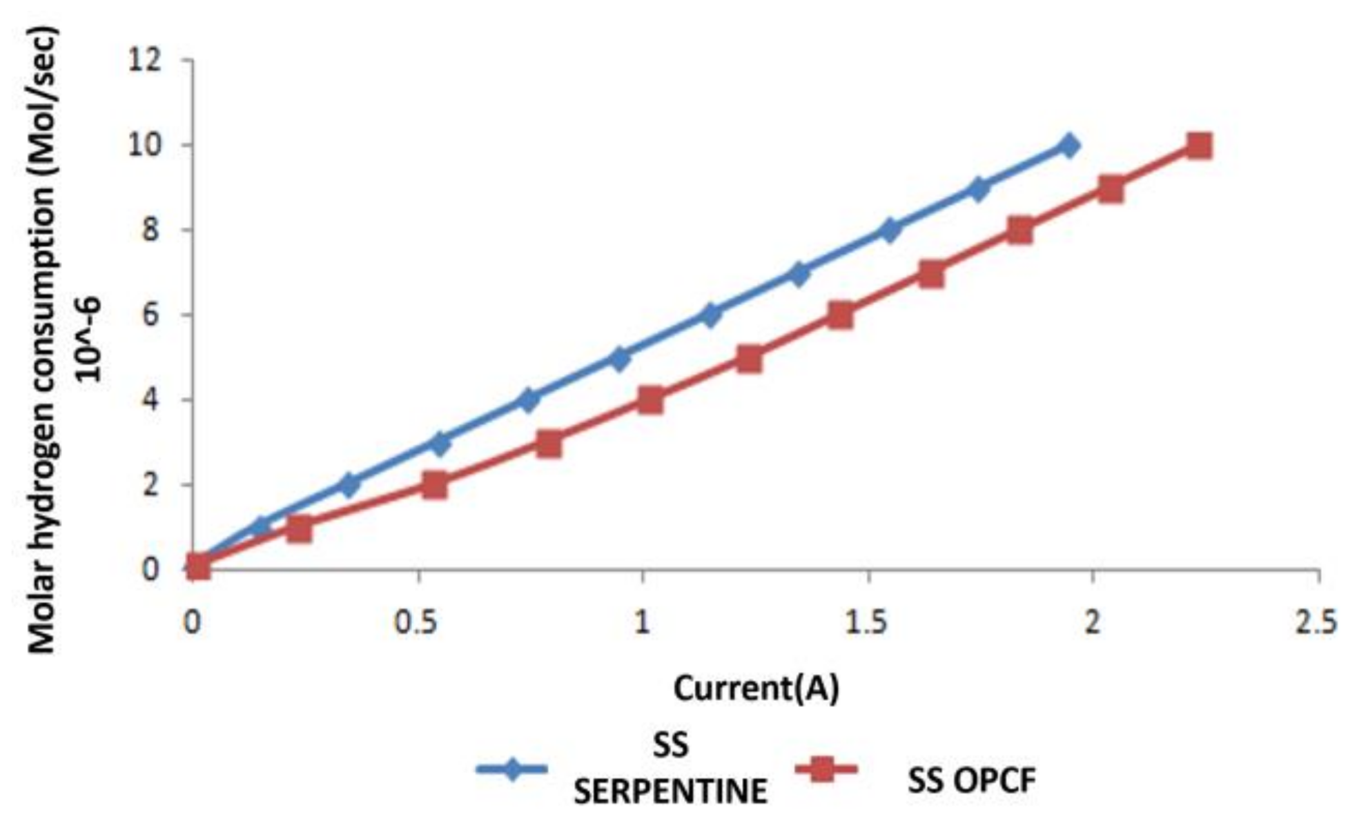
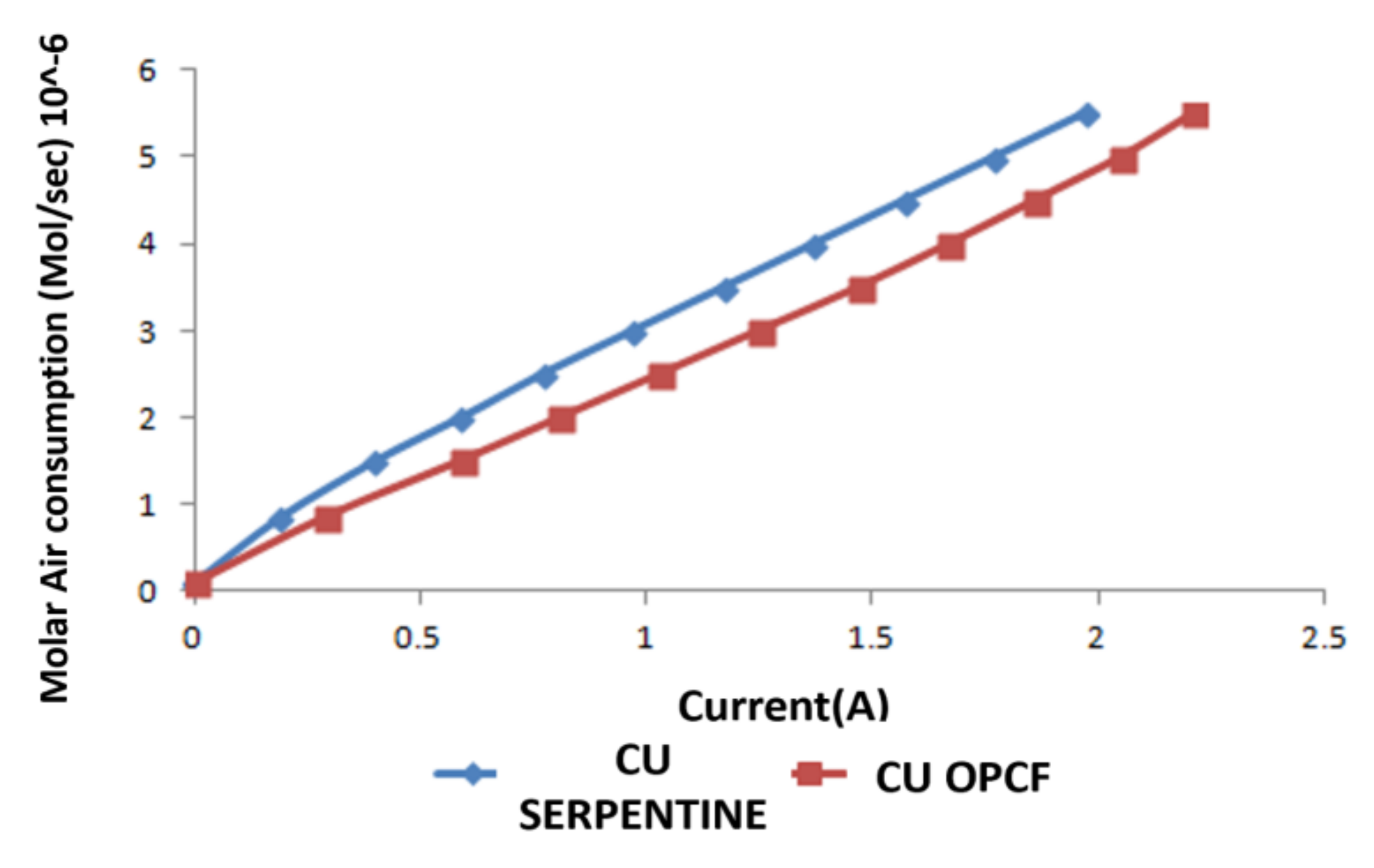
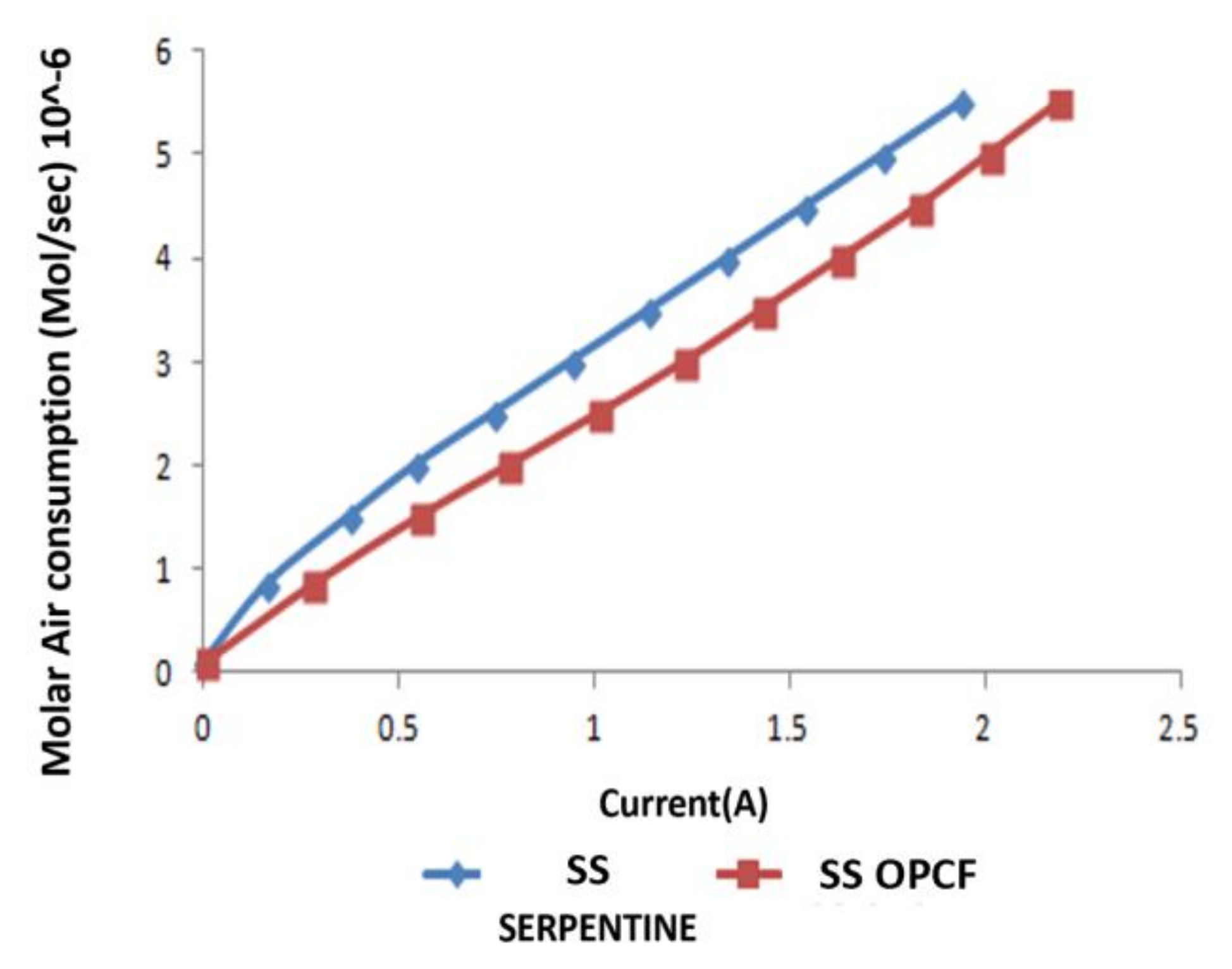
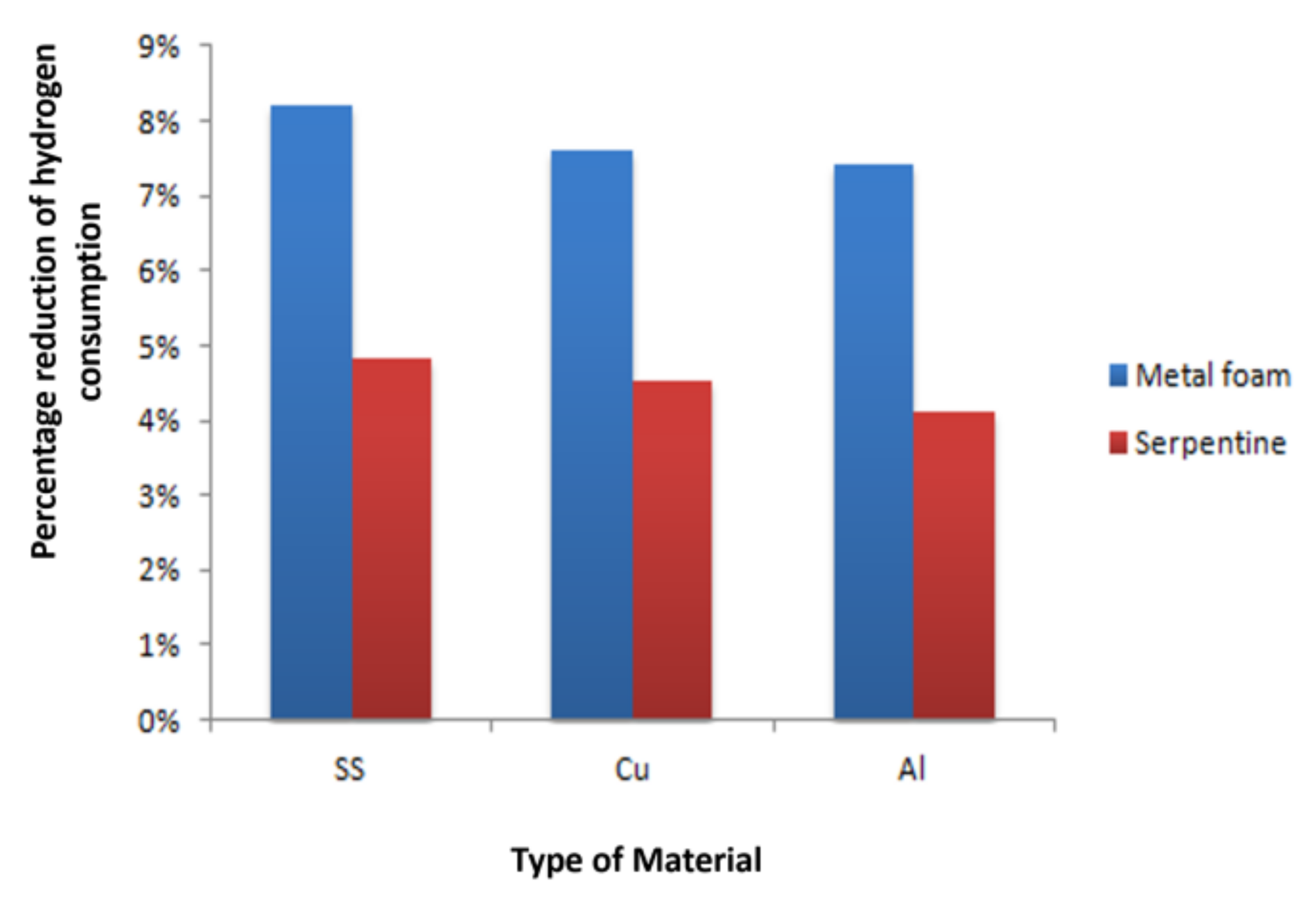
The hydrogen and oxygen consumption comparison between a different bipolar plate of OPCF and serpentine channel fuel cell performances were evaluated. Cell operational temperature was between 40–50 °C and all other parameters were constant during the experiment. OPCF displayed a superior performance than serpentine flow channel in the reactant consumption rate in all the various bipolar plate materials as shown in Figure 8, Figure 9, Figure 10, Figure 11, Figure 12 and Figure 13 respectively. OPCF bipolar plate material produces better performances with less hydrogen and air consumption than the serpentine flow channel bipolar plate. Figure 14 and Figure 15, clearly display and estimate the reduction of hydrogen and air consumption. There are approximately 4–7% reduction of hydrogen consumption for OPCF aluminium, copper and stainless steel flow plate materials and about for air consumption. Closely related procedure was carried out by Yusuf and Nihad [30]. They experimentally investigated serpentine and foam flow field channels in a fuel cell. The study concluded that aluminium foam flow channel used less hydrogen and oxygen than the serpentine flow channel. What this implies is that the reduction of hydrogen and air consumption will bring about cost savings on fuel usage. In case of fuel cell mobile applications, using OPCF bipolar plate material will last longer than serpentine bipolar plate material for the same amount of fuel. Also, using Al bipolar plate material will mean lesser reactant consumption. The result also shows that the OPCF aluminium bipolar plate has less consumption of hydrogen as well as oxidant. In practical context, weight of the fuel cell for the automotive industry is very important to make it competitive with existing technologies. As discussed earlier, flow plate is the heaviest component of fuel cell stacks. Using aluminium material for the bipolar plate will not just reduce reactant consumption but will also reduce the overall weight of the stack.

3.4. Comparison between Al, Cu and SS as OPCF Material

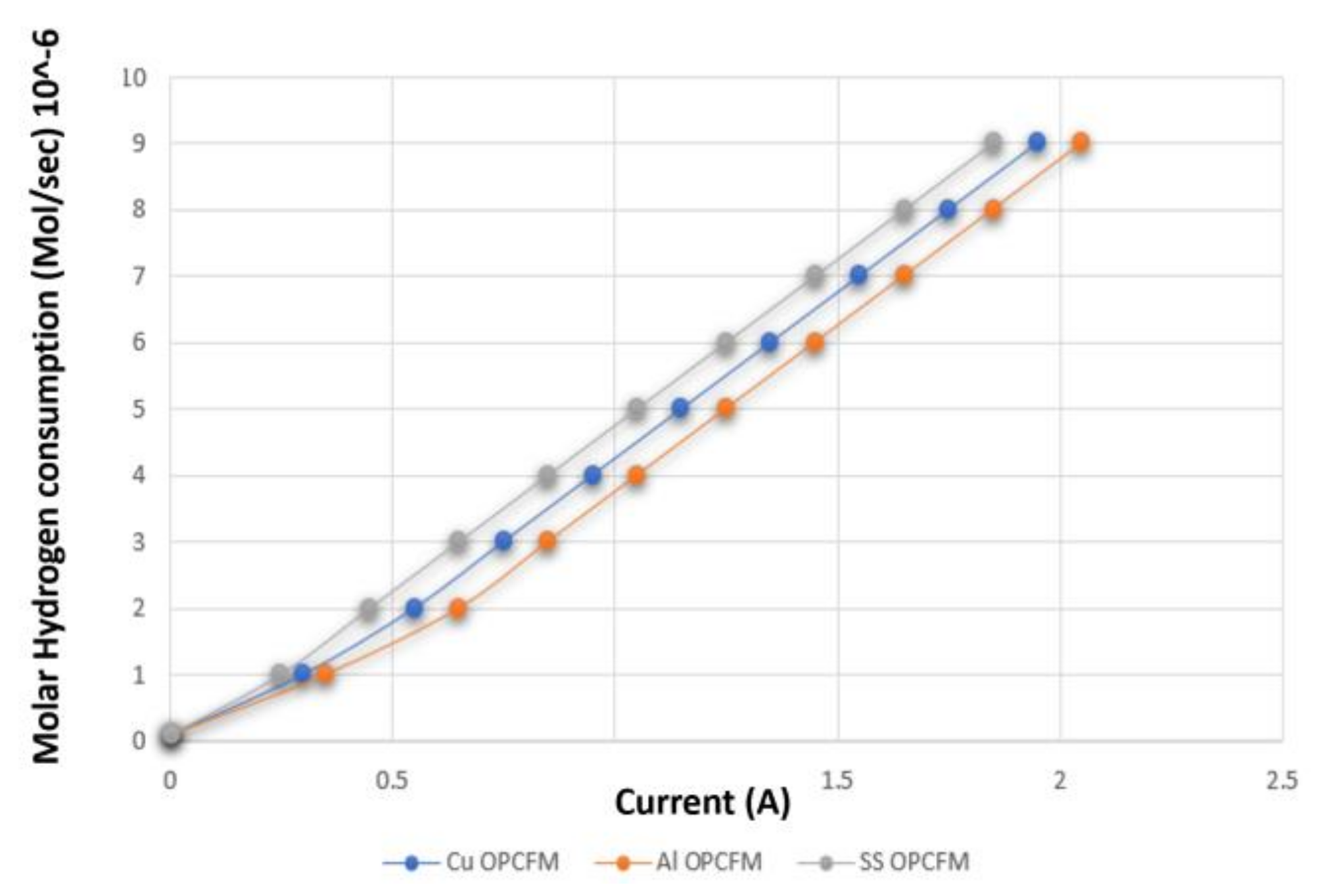
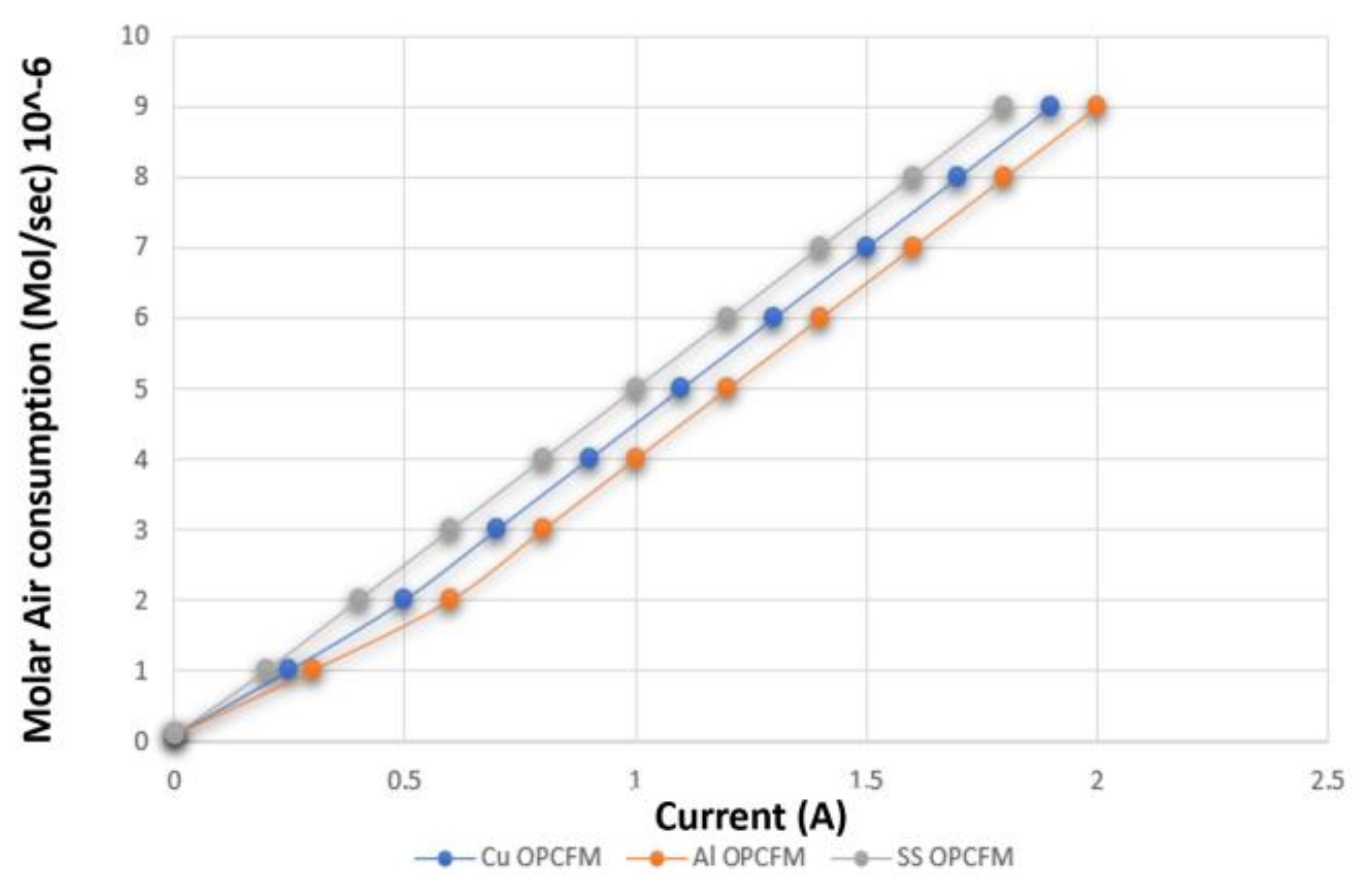
The hydrogen and oxygen consumption comparison between aluminium, copper and stainless steel flow plate for OPCFM PEM fuel cell performances from the experiment conducted in UWS lab were evaluated. The operating temperature was 323 K and the hydrogen flow rate at of 150 mL/min and oxygen at of 150 mL/min. It is seen that the more the reactant gas is consumed, the more the current generated. It is noticed that when the same amount of hydrogen was consumed for the different bipolar plate materials, more current is produced with Al materials. For instance, hydrogen consumption at the rate of 9 × 10⁶ mols/s for each material had a current of 2.05 A, 1.96 A and 1.85 A for aluminium, copper and stainless steel flow plate material respectively as seen in Figure 16. This implies that low mass transport losses can be attributed to the use of Al bipolar plate material. A similar observation is seen with oxygen consumption, as shown in Figure 17. As the current is increasing, oxygen consumption also increases. The practical implication of this means more current will be produced by using Al bipolar plate materials. These facts attest to the fact that the flow plate material have a direct impact on the efficiency of the fuel cell.

4. Experimental Validation of PEM Fuel Cell Results Using Machine Learning Algorithms

4.1. Machine Learning Models

The model considered in this work is regression modelling based on the fact that we know the input and out parameters, and it is a supervised type of machine learning.

4.2. Linear Regression

Linear regression approach modelling linearly and reveal the relationship among the dependent variable (y) and independent variables (x) [31].
Y ^ = j = 1 p 0   β ^ j   X j + β ^ 0
where Y ^ = ( y ^ 1, ……,   y ^ n)T, and y ^ i (i = 1,………, n) demonstrate the predictive value of behavioural result for ith terms, Xj = (ᵡ1j, …, ᵡnj)T and ᵡij the value of jth attribute for ith subject, and regression coefficient is β ^ j for jth attribute. For example, in a given training data set ((x1, y1), …, (xN, yN)), where the number of the training set is N, high-dimensional attribute vector (x1,1, ……, xi,p) is xi, number of attributes is p and the actual behavioural score is yi.
The main goals of linear regression [32].
  • They express the relationship accuracy;
  • They signify if there is the relationship between variables;
  • If a relationship exists, they indicate the nature of it;
  • If various variables are used, they evaluate each variables contributions.

4.3. Ridge Regression

According to Hoerl and Kennard [33], ridge regression builds a model that does minimise squared prediction error summation in the training data set. The object task is stated as:
min   i 1 N ( f ( x i ) y i ) 2 +   λ   j 1 P | | β j | | 2
This method could shrink the coefficient regression, which results in a greater generalisation for the prediction of an unseen data set. This algorithm can be used to check the trade-off among the training data predicting error using the regularisation parameter (λ). They explain that big (λ) concur with penalties on variance, while small (λ) concur with penalties on the bias. Similarly, Zaixu and Gaolang [34] describe ridge regression is better than its counterpart when it comes to multi-collinearity problems and it prevents overfitting in the variance-bias trade-off.

4.4. Polynomial Regression Algorithm

Polynomial regression is a statistical type of technique to present the relationship between features (independent variables) and output (dependent variables) with the nth degree for polynomial equation [35]. The major aims of this algorithm are to look for the optimal coefficients satisfactory predictions for the output variables relative to features used in the data set. The decision of the type and degree of polynomial regression equation differ based on the problem. In this study, cubic and quadratic polynomial functions interception method were used as shown below [36]:
f ( x ) = i = 1 n   ( α i x i + j = 1 n   β i j   x i x j ) + γ
f ( x ) = i = 1 n   [ α i x i + j = 1 n   β i j   x i x j + k = i n   σ i j k x i x j   x k     ] + γ
where γ bias term constant and α, β, σ are coefficients of the given polynomial regression function. In determining these variables, proper cost function (J) must be selected appropriately and make sure is in minimal.

4.5. Data Preparation

The machine learning allows us to predict or have an insight into our data. This type of work is done using the classification method of machine learning because we know the input and output parameters. In this study, several operating parameters with different variables for various aluminium, copper and stainless steel flow plate materials were utilized as input variables for the data collections; hydrogen inlet pressure, hydrogen inlet humidification temperature, operating temperature of the fuel cell, hydrogen and oxygen consumption. While the output variable is the current density. At varying operational conditions of the cell, the results obtained were used in preparing the data for validation. For example, the inlet temperatures ranging from 20 °C to 80 °C and inlet pressures from 1.5 bar to 2.5 bar were all covered in the work. The data collected were divided randomly into training and testing data sets in the algorithms for modelling as seen in Figure 18.
It must however be highlighted that in recent times, there are more advanced machine learning techniques which tends to give superior outcomes and some of these algorithms may become primary point of focus for future work [37,38].

4.6. Results and Discussion

The data was processed using the python programming language (Anaconda). The training dataset has 175 observations and it was used in training the model. The exploratory analysis was carried out by evaluating the plots and tables of the uploaded dataset. The column names were re-mapped to eliminate duplicates. The summary statistics were calculated by row and column for the array of numeric variables. These algorithms were compared in this work; linear regression, ridge regression and polynomial regression to predict the performance of the PEM fuel cell operation. The predictive performance of the models are shown in Table 3; it is clear that linear regression has the highest accuracy of 72%, followed by ridge and polynomial regression with 68 and 54% respectively. Although the results given is satisfactory, the models can still be improved by employing hyper-parameters tuning.

5. Conclusions

To accelerate the commercialization of fuel cells in varying applications, introduction of novel but cheaper materials should become a bone of contention in future research activities especially if fuel cells are to compete with existing technologies. This study explored the utilization of aluminium, copper and stainless steel in the development of novel flow channels to examine their impact on the overall cell performance. With the aid of polarization curves generated at varying operating conditions, it was deduced that the flow plate made of aluminium exhibited good performance in terms of fuel and oxidant consumption compared to the other materials considered in the investigation. This phenomenon had a direct correlation to the ionic conductivity within the membrane of the cell.
Data gathered for the overall performance for Al, Cu and SS bipolar plate materials using open-pore metal foam and serpentine flow field channel in PEM fuel cell was equally presented. The results show that all bipolar plate materials for OPCF outperformed the serpentine channels. The aluminium, copper and stainless-steel flow plate material for OPCF provided and maintained better polarization curves for the reactants humidification temperatures and operating pressures. Similarly, Al bipolar plate materials for OPCF exhibited the best performance compared to Cu and SS due to reactant molecules stability on aluminium surfaces. The Al bipolar plate materials (with OPCF) provides low weight and less fuel consumption of about 4 percent when compared to Cu and SS bipolar plate materials (with OPCF). Consequently, Machine Learning using Python for the validation of the results with Linear regression, Ridge regression and Polynomial regression algorithm. It was clear from the model results that linear regression has the highest accuracy of 72%, followed by ridge and polynomial regression with 68 and 54% respectively.

Author Contributions

Conceptualization, T.W., O.I., E.O. and A.G.O.; methodology T.W. and A.B.; software, O.I. and A.G.O.; validation, T.W., E.O. and A.G.O.; formal analysis, T.W. and A.B.; investigation, T.W., A.B., O.I., E.O. and A.G.O.; resources, A.G.O.; data curation, T.W.; writing—original draft preparation, T.W., A.B. and A.G.O.; writing—review and editing, T.W., O.I. and A.G.O.; visualization, T.W., O.I., A.G.O. and A.B.; supervision, T.W., A.B. and A.G.O.; project administration, T.W., A.B. and A.G.O.; funding acquisition, T.W., E.O., O.I. and A.G.O. All authors have read and agreed to the published version of the manuscript.

Funding

This research received no external funding.

Conflicts of Interest

The authors declare no conflict of interest.

References

  1. Olabi, A.; Wilberforce, T.; Sayed, E.T.; Elsaid, K.; Abdelkareem, M.A. Prospects of Fuel Cell Combined Heat and Power Systems. Energies 2020, 13, 4104. [Google Scholar] [CrossRef]
  2. Ijaodola, O.; Ogungbemi, E.; Khatib, F.N.; Wilberforce, T.; Ramadan, M.; El-Hassan, Z.; Thompson, J. Energy efficiency improvements by investigating the water flooding management on proton exchange membrane fuel cell (PEMFC). Energy 2019, 179, 246–267. [Google Scholar] [CrossRef]
  3. Ijaodola, O.; Ogungbemi, E.; Khatib, F.N.; Wilberforce, T.; Ramadan, M.; El Hassan, Z.; Thompson, J.; Olabi, A.G. Evaluating the Effect of Metal Bipolar Plate Coating on the Performance of Proton Exchange Membrane Fuel Cells. Energies 2018, 11, 3203. [Google Scholar] [CrossRef] [Green Version]
  4. Ogungbemi, E.; Ijaodola, O.; Khatib, F.N.; Wilberforce, T.; El Hassan, Z.; Thompson, J.; Ramadan, M.; Olabi, A.G. Fuel cell membranes—Pros and cons. Energy 2019, 172, 155–172. [Google Scholar] [CrossRef] [Green Version]
  5. Wilberforce, T.; Ijaodola, O.; Ogungbemi, E.; El Hassan, Z.; Thompson, J.; Olabi, A.G. Effect of bipolar plate materials on performance of fuel cells. In Reference Module in Materials Science and Materials Engineering; Elsevier: Amsterdam, The Netherlands, 2018. [Google Scholar]
  6. Alaswad, A.; Palumbo, A.; Dassisti, M.; Olabi, A.G. Fuel cell technologies, applications, and state of the art: A reference guide. In Encyclopedia of Smart Materials; Elsevier: Amsterdam, The Netherlands, 2022; pp. 315–333. [Google Scholar] [CrossRef]
  7. Smitha, B.; Sridhar, S.; Khan, A. Solid polymer electrolyte membranes for fuel cell applications—A review. J. Membr. Sci. 2005, 259, 10–26. [Google Scholar] [CrossRef]
  8. Yun, W.; Ken, S.C.; Jeffrey, M.; Sung, C.C.; Xavier, C.A. A review of polymer electrolyte membrane fuel cells: Technology, applications, and needs on fundamental research. Appl. Energy 2011, 88, 981–1007. [Google Scholar] [CrossRef] [Green Version]
  9. Shahrukh, S.; Sudhakar, K.; Brajesh, C.; Jamil, A. A review on recent advances in proton exchange membrane fuel cells: Materials, technology and applications. Pelagia Res. Libr. Adv. Appl. Sci. Res. 2015, 6, 89–100. [Google Scholar]
  10. Lin, W.; Attila, H.; Tianhong, Z.; Hongtan, L. A parametric study of PEM fuel cell performances. Int. J. Hydrog. Energy 2003, 28, 1263–1272. [Google Scholar] [CrossRef]
  11. Barreto, L.; Makihira, A.; Riahi, K. The hydrogen economy in the 21st century: A sustainable development scenario. Int. J. Hydrog. Energy 2003, 28, 267–284. [Google Scholar] [CrossRef] [Green Version]
  12. Abdin, Z.; Webb, C.; Gray, E. PEM fuel cell model and simulation in Matlab–Simulink based on physical parameters. Energy 2016, 116, 1131–1144. [Google Scholar] [CrossRef]
  13. Yafei, C.; Yanzhou, Q.; Yan, Y.; Junfeng, Z.; Xianguo, L. Humidification strategy for polymer electrolyte membrane fuel cells. A review. Appl. Energy 2018, 230, 643–662. [Google Scholar] [CrossRef]
  14. Wilberforce, T.; El-Hassan, Z.; Khatib, F.N.; Al Makky, A.; Baroutaji, A.; Carton, J.G.; Olabi, A.G. Developments of electric cars and fuel cell hydrogen electric cars. Int. J. Hydrog. Energy 2017, 42, 25695–25734. [Google Scholar] [CrossRef] [Green Version]
  15. Khazaee, I.; Sabadbafan, H. Effect of humidity content and direction of the flow of reactant gases on water management in the 4-serpentine and 1-serpentine flow channel in a PEM (proton exchange membrane) fuel cell. Energy 2016, 101, 252–265. [Google Scholar] [CrossRef]
  16. Yousfi-Steiner, N.; Moçotéguy, P.; Candusso, D.; Hissel, D.; Hernandez, A.; Aslanides, A. A review on PEM voltage degradation associated with water management: Impacts, influent factors and characterization. J. Power Sources 2008, 183, 260–274. [Google Scholar] [CrossRef]
  17. Judith, O.; Manikandan, R.; Murat, A. In situ detection of anode flooding of a PEM fuel cell. Int. J. Hydrog. Energy 2009, 34, 6765–6770. [Google Scholar] [CrossRef]
  18. Li, Y.; Zhou, Z.; Liu, X.; Wu, W.-T. Modeling of PEM fuel cell with thin MEA under low humidity operating condition. Appl. Energy 2019, 242, 1513–1527. [Google Scholar] [CrossRef]
  19. Kumar, A.; Reddy, R.G. Polymer Electrolyte Membrane Fuel Cell with Metal Foam in the Gas Flow-Field of Bipolar/End Plates. J. New Mat. Electrochem. Syst. 2003, 6, 231–236. [Google Scholar]
  20. Sierra, J.; Figueroa-Ramírez, S.; Díaz, S.; Vargas, J.; Sebastian, P. Numerical evaluation of a PEM fuel cell with conventional flow fields adapted to tubular plates. Int. J. Hydrog. Energy 2014, 39, 16694–16705. [Google Scholar] [CrossRef]
  21. Ogungbemi, E.; Wilberforce, T.; Ijaodola, O.; Thompson, J.; Olabi, A.G. Review of operating condition, design parameters and material properties for proton exchange membrane fuel cells. Int. J. Energy Res. 2021, 45, 1227–1245. [Google Scholar] [CrossRef]
  22. Carton, J.; Olabi, A.G. Three-dimensional proton exchange membrane fuel cell model: Comparison of double channel and open pore cellular foam flow plates. Energy 2017, 136, 185–195. [Google Scholar] [CrossRef] [Green Version]
  23. Tseng, C.; Heush, Y.; Chiang, C.; Lee, Y.; Lee, K. Application of metal foams to high temperature PEM fuel cells. Int. J. Hydrog. Energy 2016, 41, 16196–16204. [Google Scholar] [CrossRef]
  24. Shimpalee, S.; Lilavivat, V.; McCrabb, H.; Khunatorn, Y.; Lee, H.-K.; Lee, W.-K.; Weidner, J. Investigation of bipolar plate materials for proton exchange membrane fuel cells. Int. J. Hydrog. Energy 2016, 41, 13688–13696. [Google Scholar] [CrossRef] [Green Version]
  25. Wilberforce, T.; Khatib, F.; Ijaodola, O.; Ogungbemi, E.; El-Hassan, Z.; Durrant, A.; Thompson, J.; Olabi, A. Numerical modelling and CFD simulation of a polymer electrolyte membrane (PEM) fuel cell flow channel using an open pore cellular foam material. Sci. Total Environ. 2019, 678, 728–740. [Google Scholar] [CrossRef] [PubMed]
  26. Tseng, C.-J.; Tsai, B.T.; Liu, Z.-S.; Cheng, T.-C.; Chang, W.-C.; Lo, S.-K. A PEM fuel cell with metal foam as flow distributor. Energy Convers. Manag. 2012, 62, 14–21. [Google Scholar] [CrossRef]
  27. Mohammad, S.H.; Bahman, S. Metal foams application to enhance cooling of open cathode polymer electrolyte membrane fuel cells. J. Power Sources 2015, 295, 275–291. [Google Scholar] [CrossRef]
  28. Wilberforce, T.; Ijaodola, O.; Khatib, F.; Ogungbemi, E.; El Hassan, Z.; Thompson, J.; Olabi, A. Effect of humidification of reactive gases on the performance of a proton exchange membrane fuel cell. Sci. Total Environ. 2019, 688, 1016–1035. [Google Scholar] [CrossRef]
  29. Yupeng, Y.; Xu, Z.; Liejin, G.; Hongtan, L. Overall and local effects of operating conditions in PEM fuel cells with dead-ended anode. Int. J. Hydrog. Energy 2017, 42, 4690–4698. [Google Scholar] [CrossRef] [Green Version]
  30. Yussef, A.; Nihad, D. Experimental performance assessment of metal-foam flow fields for proton exchange membrane fuel cells. Appl. Energy 2019, 252, 113458. [Google Scholar] [CrossRef]
  31. Ding, S.; Jiang, W.; Shen, Z. Linear-regression models and algorithms based on the Total-Least-Squares principle. Geod. Geodyn. 2012, 3, 42–46. [Google Scholar] [CrossRef] [Green Version]
  32. Shiu-tong, T.N.; Martin, S.; Keung, F.W. Using genetic algorithms and linear regression analysis for private housing demand forecast. Build. Environ. 2008, 43, 1171–1184. [Google Scholar] [CrossRef] [Green Version]
  33. Arthur, E.H.; Robert, W.K. Ridge Regression: Biased Estimation for Nonorthogonal Problems. American Statistical Association and American Society for Quality. Technometrics 1970, 12, 55–67. [Google Scholar] [CrossRef]
  34. Zaixu, C.; Gaolang, G. The effect of machine learning regression algorithms and sample size on individualized behavioral prediction with functional connectivity features. NeuroImage 2018, 178, 622–637. [Google Scholar] [CrossRef]
  35. Yani, Z.; Chaoyang, Z.; Xiaoxin, L. Improved principal component analysis and linear regression classification for face recognition. Signal Process. 2018, 145, 175–182. [Google Scholar] [CrossRef]
  36. Dhruva, G.; Saraju, P.M.; Garima, T. Fast optimization of nano-CMOS voltage-controlled oscillator using polynomial regression and genetic algorithm. Microelectron. J. 2013, 44, 631–641. [Google Scholar] [CrossRef]
  37. Zhong, S.; Zhang, K.; Bagheri, M.; Burken, J.G.; Gu, A.; Li, B.; Ma, X.; Marrone, B.L.; Ren, Z.J.; Schrier, J.; et al. Machine Learning: New Ideas and Tools in Environmental Science and Engineering. Environ. Sci. Technol. 2021, 55, 12741–12754. [Google Scholar] [CrossRef]
  38. Ding, R.; Ding, Y.; Zhang, H.; Wang, R.; Xu, Z.; Liu, Y.; Yin, W.; Wang, J.; Li, J.; Liu, J. Applying machine learning to boost the development of high-performance membrane electrode assembly for proton exchange membrane fuel cells. J. Mater. Chem. A 2021, 9, 6841–6850. [Google Scholar] [CrossRef]
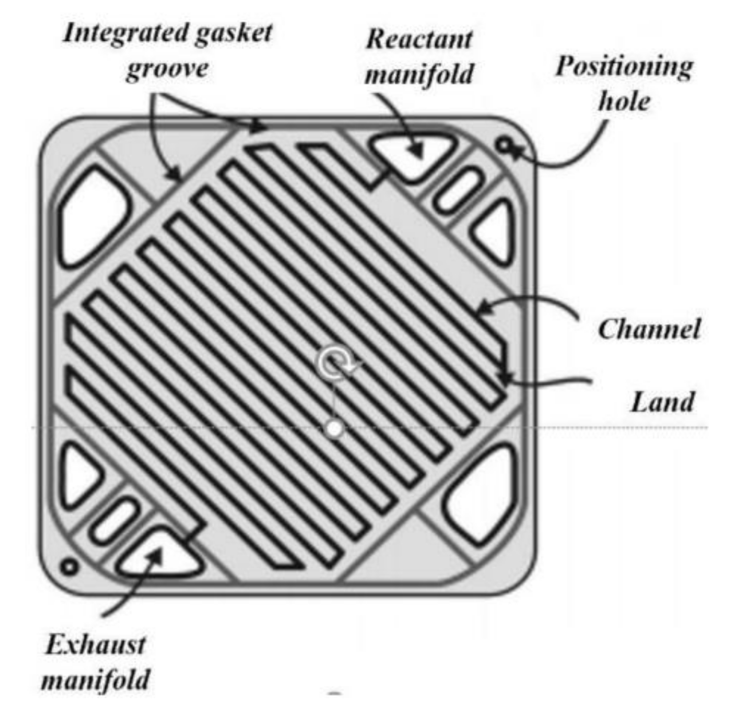
Figure 1. Part of a flow plate [3].
Energies 15 01886 g001
Figure 2. PEM fuel cell with open pore cellular foam material permission to reproduced [22].
Energies 15 01886 g002
Figure 3. (a) Laboratory set-up (b) Development of the novel fuel cell using open pore cellular foam material.
Energies 15 01886 g003
Figure 4. Hydrogen humidification temperature 40 °C.
Energies 15 01886 g004
Figure 5. Hydrogen humidification temperature 60 °C.
Energies 15 01886 g005
Figure 6. Hydrogen humidification temperature 80 °C.
Energies 15 01886 g006
Figure 7. Effect of different operating pressure at 1.5, 2.0 and 2.5 bar polarization curve.
Energies 15 01886 g007
Figure 8. Hydrogen consumption (Al bipolar plate material).
Energies 15 01886 g008
Figure 9. Hydrogen consumption (Cu bipolar plate material).
Energies 15 01886 g009
Figure 10. Hydrogen consumption (SS bipolar plate material).
Energies 15 01886 g010
Figure 11. Air consumption (Al bipolar plate material).
Energies 15 01886 g011
Figure 12. Air consumption (Cu bipolar plate material).
Energies 15 01886 g012
Figure 13. Air consumption (SS bipolar plate material).
Energies 15 01886 g013
Figure 14. A comparison of percentage reduction of hydrogen consumption between Al, Cu and SS bipolar plate material between metal foam and serpentine flow channel.
Energies 15 01886 g014
Figure 15. A comparison of percentage reduction of Air consumption between Al, Cu and SS bipolar plate material between metal foam and serpentine flow field channel.
Energies 15 01886 g015
Figure 16. Hydrogen consumption for Al, Cu and SS OPCFM flow plate material.
Energies 15 01886 g016
Figure 17. Air consumption for Al, Cu and SS OPCFM flow plate material.
Energies 15 01886 g017
Figure 18. Methods of building the machine learning process.
Energies 15 01886 g018
Table 1. Operating characteristics of fuel cells.
CategoryTemperatures (°C)Electrical PerformanceCharge CarrierFuelElectrolyte
Molten carbonate fuel cells (MCFCs)(600–700 °C)(65–70%)CO32−MethaneMolten carbonate salt immerse in a porous matrix
Solid oxide fuel cells (SOFCs),(800–1000 °C)(50–65%)O2−MethaneYttria-stabilized zirconia (YSZ)
Alkaline fuel cells (AFCs),(80–150 °C)(40–70%)OHHydrogenPotassium hydroxide(KOH)
phosphoric acid fuel cells (PAFCs)(150–200 °C)(37–42%).H+HydrogenPhosphoric acid(H₃PO₄) immerse in a porous mix
Proton exchange membrane (PEM) fuel cells(60–80 °C)(40–55%)H+HydrogenPolymer membrane electrolyte (Nafion)
Table 2. Experimental investigation reports examined.
ReportsUnit
Maximum currentA
Maximum voltageV
Maximum voltage efficiency%
Current intercept (I–V graph)A
Hydrogen consumptiongs−1
Hydrogen fuel efficiency%
Oxygen consumptiongs−1
Oxygen fuel efficiency%
Table 3. Predictive performance of the models used in the investigation.
Machine Learning Algorithm (MLA)Algorithm Accuracy
0Linear Regression0.72
1Polynomial Regression0.54
2Ridge Regression0.68
Publisher’s Note: MDPI stays neutral with regard to jurisdictional claims in published maps and institutional affiliations.