1. Introduction
Thanks to the simple structure and robust rotor without a brush and slip ring, the synchronous reluctance motor (SynRM) has become an attractive candidate [
1,
2,
3]. Conventional SynRMs employ distributed windings to obtain essentially sinusoidal back electromotive force (back-EMF) per phase and a high winding factor [
4,
5,
6,
7]. However, due to the long end-part winding length, distributed windings result in increased copper loss, decreased efficiency and power density. On the other hand, concentrated windings are rarely employed for SynRMs because of the high harmonic distortion in armature windings and low winding factor. Spargo and other authors introduce fractional slot concentrated windings (FSCW) to SynRM, with a segment stator to improve torque density and efficiency [
8,
9,
10,
11,
12,
13,
14], e.g., the 6-slot 4-pole (6/4) SynRel machine. The 6/4 machine exhibits a comparable performance of a permanent magnet (PM)-assisted SynRM with a high torque output capability and a low level of torque ripple [
8,
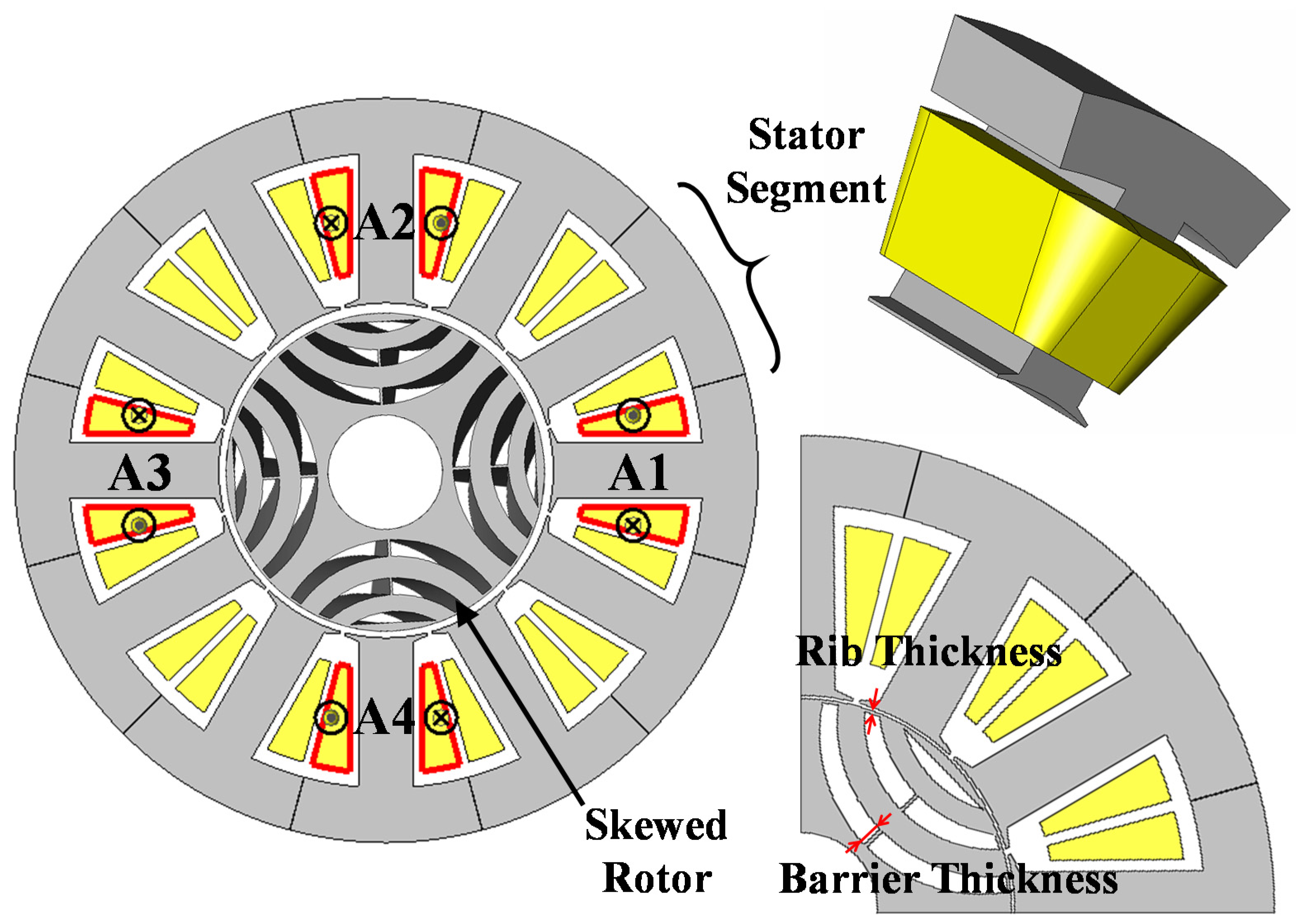
9]. The proposed 12/4 CW machine exhibits comparable torque performance, compared to the case of adopting distributed winding, when the total stack length is unchanged. The short winding end, PM-free and very low mutual inductances of the 12/4 CW machine will be appreciated by applications where a short stack length, high robustness and low cost are required, such as the integrated starter generator (ISG) in low-cost wild hybrid vehicles. The ISG is located between the engine and the gear box, and drives the output shaft directly. First of all, the vehicle producer requires a brushless and PM-less motor and concentrated windings. Getting rid of permanent magnets reduces the cost and enhances robustness and speed range. Avoiding distributed windings improves the air flow and makes it more dustproof, as well as other mechanical considerations. These above requirements leave only the choices of the reluctance motor and SynRM. The 9/6 or 15/8 SynRM are not considered due to unbalanced radial forces on the rotor. More importantly, low mutual inductances between armature phases is highly appreciated, since it will facilitate a high fault-tolerant capability, which can be found in the 12/4 SynRM machine.
Consequently, the magnetic equivalent circuit (MEC) model is built to predict electromagnetic performance, including air-gap flux density distributions, winding inductances and electromagnetic torque. Then, the obtained results are validated by 2D-finite element analysis (2D-FEA). Furthermore, aiming at better torque performances and lower total harmonic distortion (THD) in phase voltage, the optimization of the 12/4 SynRM is carried out combing the MEC and Taguchi method. Unlike traditional optimization methods using FEA coupling optimization algorithms, such as a genetic algorithm [
15,
16,
17,
18] and particle swarm algorithm [
19,
20,
21,
22], the Taguchi method exhibits the merit of being less time consuming [
23,
24,
25,
26]. This merit can be greatly enhanced by using MEC instead of FEA, maintaining satisfactory accuracy.
3. Magnetic Equivalent Circuit Method and Evaluation
As an efficient tool, the MEC method has been widely utilized to analyze the electromagnetic performance of electrical machines [
27,
28], and is considered as a compromise between FEA with high accuracy and an analytical method (AM) with straightforward physical connections of performance and geometrical parameters. Therefore, the MEC model of the 12/4 SynRM is built in this paper.
Figure 2 illustrates a quarter of the 12/4 machine, where each specific magnetic path is illustrated by a different MEC branch. The SynRM is separated into segments according to the geometrical shape. The equivalent permeance of each part of the stator and rotor core can be calculated using the permeance equations.
The basic equation which governs each branch of the magnetic circuit is given by,
In Equation (1),
Φ,
G and
F are the flux, permeance and magnetic-motive-force (MMF), respectively. In Equation (2),
μr,
μ0,
S and
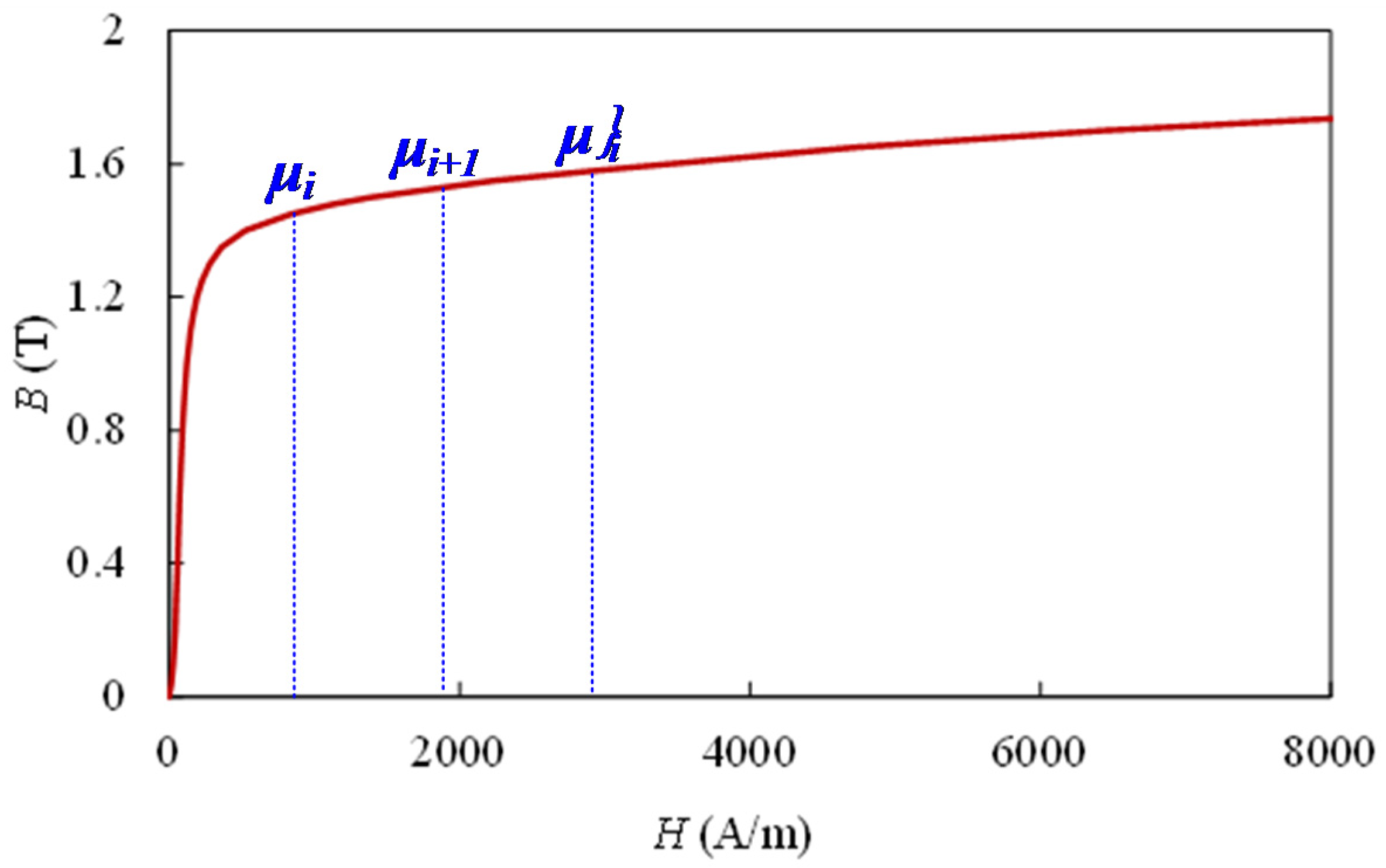
l are the relative permeability, the permeability of free space, the cross-section area and the length, respectively. Specifically,
μr is determined by iteration from the
B–H curve of the lamination material. The permanent magnets can simply be modeled as an equivalent MMF [
29],
and permeance,
where
hm and
lm are the magnet thickness and width, respectively, and
Br is the remanence.
Then, the MEC model is solved by MATLAB following the flow chart shown in
Figure 3. The saturation in iron is counted in by the iteration of
μr. For each branch in the magnetic circuit at the
ith step in an iteration, the condition of convergence
ε is defined as,
where
μi is the permeance given before equation solving, and
μ’i is the real permeance obtained after the equation solving, as shown in
Figure 4. If
ε ≤ 10
−6 is not achieved, the permeance at the (
i + 1)th step in an iteration is given by Equation (6) and
k = 0.5 in this case.
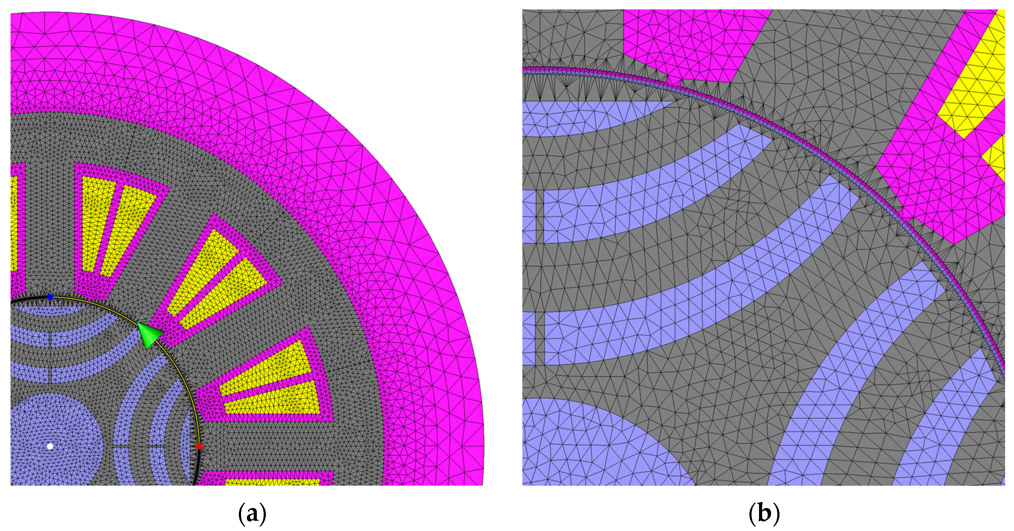
Figure 5 shows the mesh results of the FEA model in which the air-gap consists of 6 layers of elements. The path to plot the air-gap flux density distribution is also given in
Figure 5a, which covers 1/4 of the air-gap. The air-gap flux density distributions generated by phase-A current, d-axis current and q-axis current, respectively, are predicted by MEC and then compared to the FEA results by
Figure 6. Overall, satisfied agreements are achieved.
4. Results and Discussion
When the MEC model of the 12/4 SynRM motor is solved, the electromagnetic characteristics can be easily calculated, e.g., the flux in the air-gap (
ΦA), coil flux linkage (
Ψa), phase-A self-inductance (
Laa) and mutual inductance between phase-A and -B (
Mba) can be obtained by
Then, the
Ld (d-axis),
Lq (q-axis) and
Ldq (d-q coupled inductance) can be calculated by Equations (11) and (12).
Figure 7 compares the MEC and FEA obtained inductances with good agreements.
It should be noted that in the 12/4 SynRM with concentrated windings, there is a cross-coupling between the d-axis and q-axis, i.e., the
Ldq contributes unneglectable electromagnetic torque, as given in Equation (14).
where
p is the rotor pole-pairs,
Ld and
Lq is the d- and q-axis inductance, respectively, and
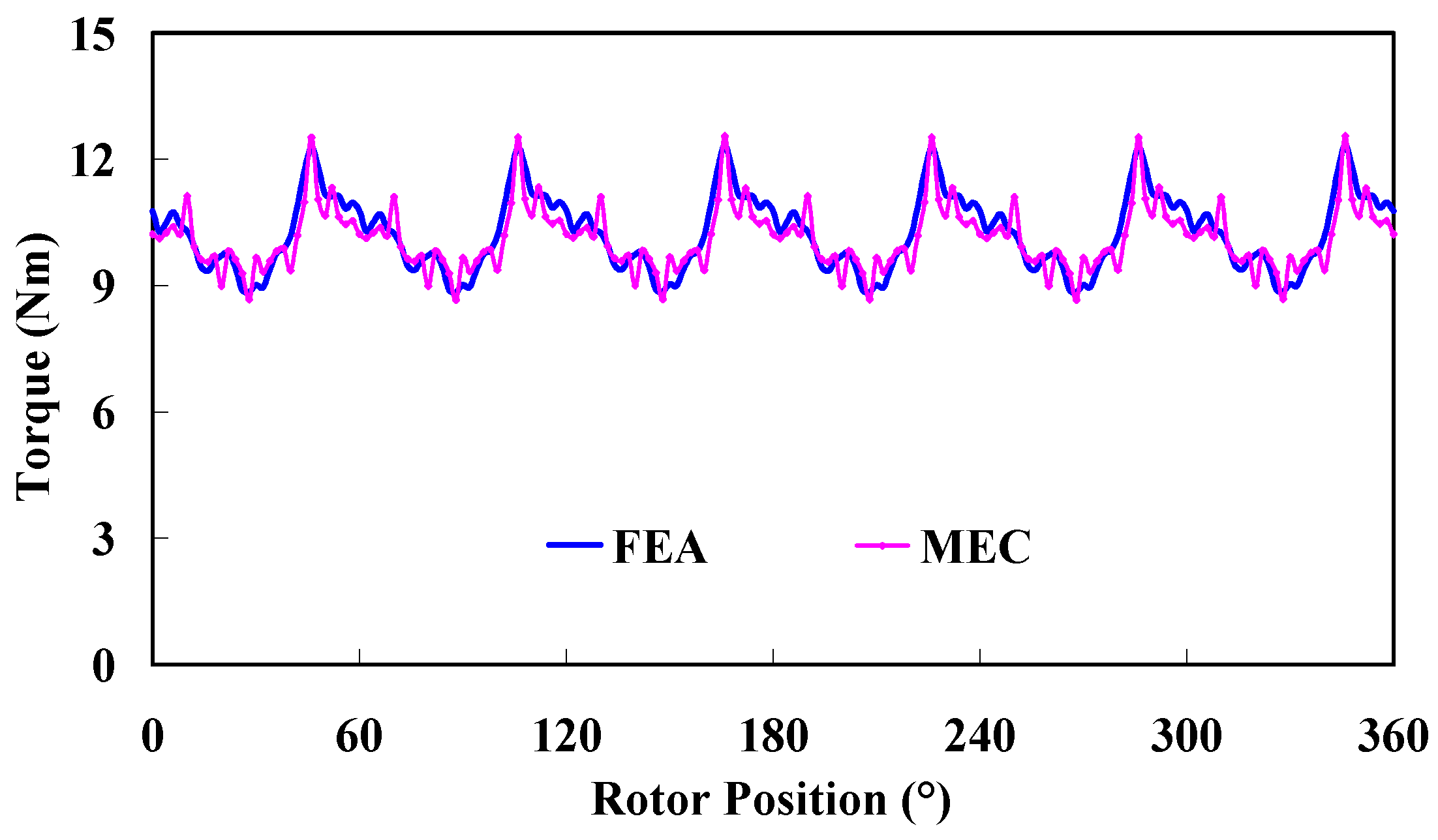
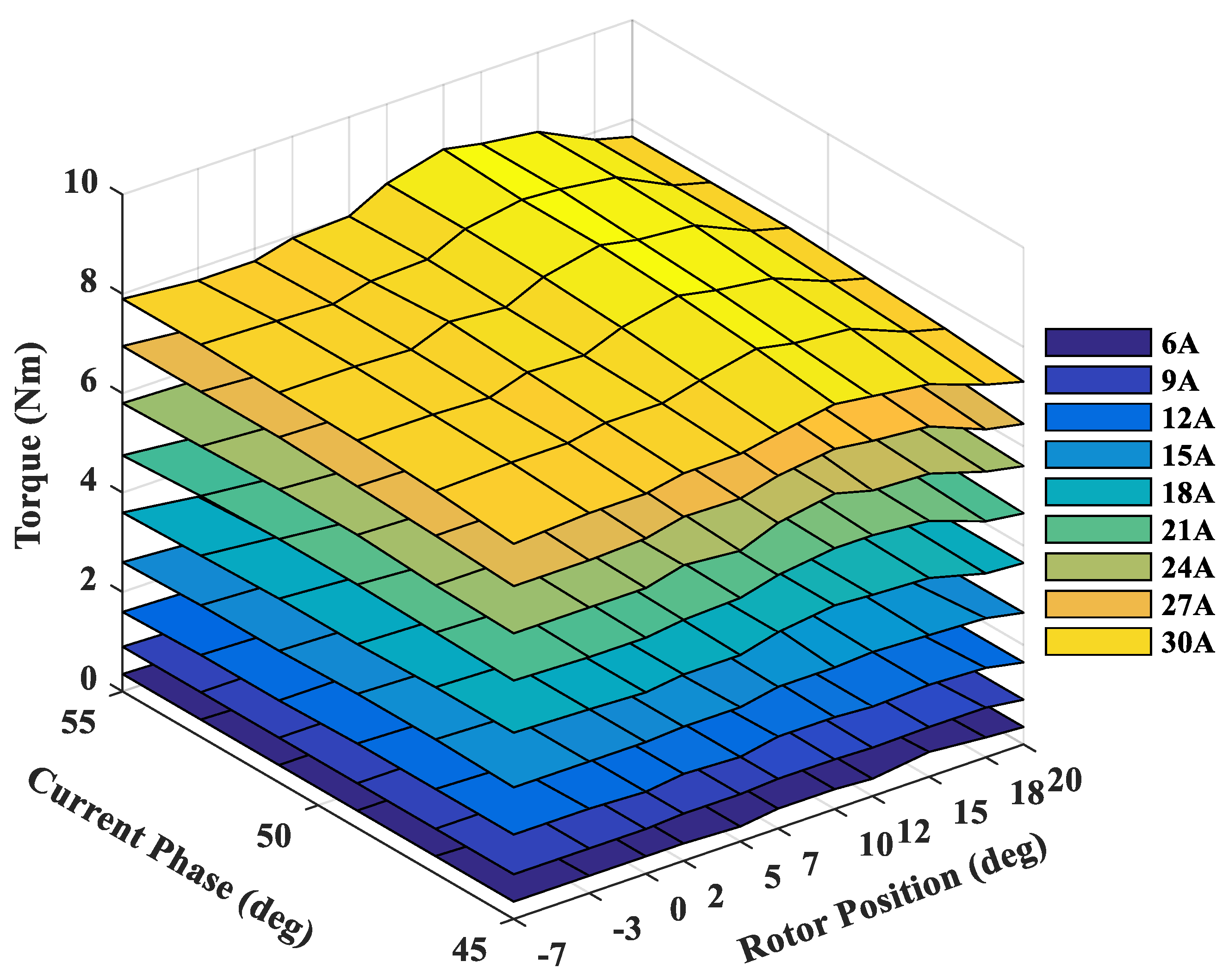
α is the current phase angle, i.e., the angle between the current vector and d-axis. Thus, the torque waveform can be calculated.
Figure 8 and
Figure 9 give the torque performance versus current phases and rotor position, respectively. As can be seen, good agreements are achieved between the MEC and FEA results.
5. Optimization of Torque Characters Based on MEC and Taguchi Method
The Taguchi method is chosen as one of the many optimization methods. The optimization methods introduced in
Section 1 require sophisticated algorithms and additional programming and data processing along with a lot of FEA cases of electromagnetic field. So, the methods are usually time consuming and complex. On the other hand, the Taguchi method can obtain satisfactory results by reduced calculation cases, and thus is less time consuming. In this paper, the Taguchi method and the MEC model are used to optimize the SynRM. The steps in the Taguchi method are as follows [
30]:
First of all, the means of all results
Mt(S) and average effect
MXj can be calculated as
where
Xi and
Yi are factor-level and performances, respectively. Then, the analysis of variance is carried out, which provides a measure of confidence. The technique does not directly analyze the data, but rather determines the variance of the data. The sum of squares (
SS) is calculated first. It is a measure of the deviation of the experimental data from the mean value of the data. The sum of squares due to various factors can be calculated as
where
Mt(
S) and
Mxpj(
Y) are results of Equations (5) and (6). SS shows the relative importance of various factors on machine performance. Then, the Pearson coefficient is chosen to calculate the coefficient of correlation and given as
The optimization aim is a larger average torque (
Tavg), lower torque ripple (
Trip) and lower THD of phase voltage (
THDU). Firstly, the optimization parameters are determined and shown in
Figure 10 and listed in
Table 2, which are related to the rotor barriers and ribs, stator tooth and yoke width.
The design of the exam is carried out after preparing the initial information. To obtain the number of exams, the orthogonal arrays are presented using Taguchi. The exams’ matrix can be easily created using existing software, in this case the Minitab. Shown in
Table 3 are the Taguchi experiments that are tailored to their parameters and levels. The rows of the exams table represent the levels of factors in each experiment, and its columns represent the number of factors.
Using the results of experiments designed using the Taguchi method and after analyzing the results of the experiments, the optimal combination of factor levels and output voltage and cost values are calculated at the optimal point. The effect of each level is listed in
Table 4.
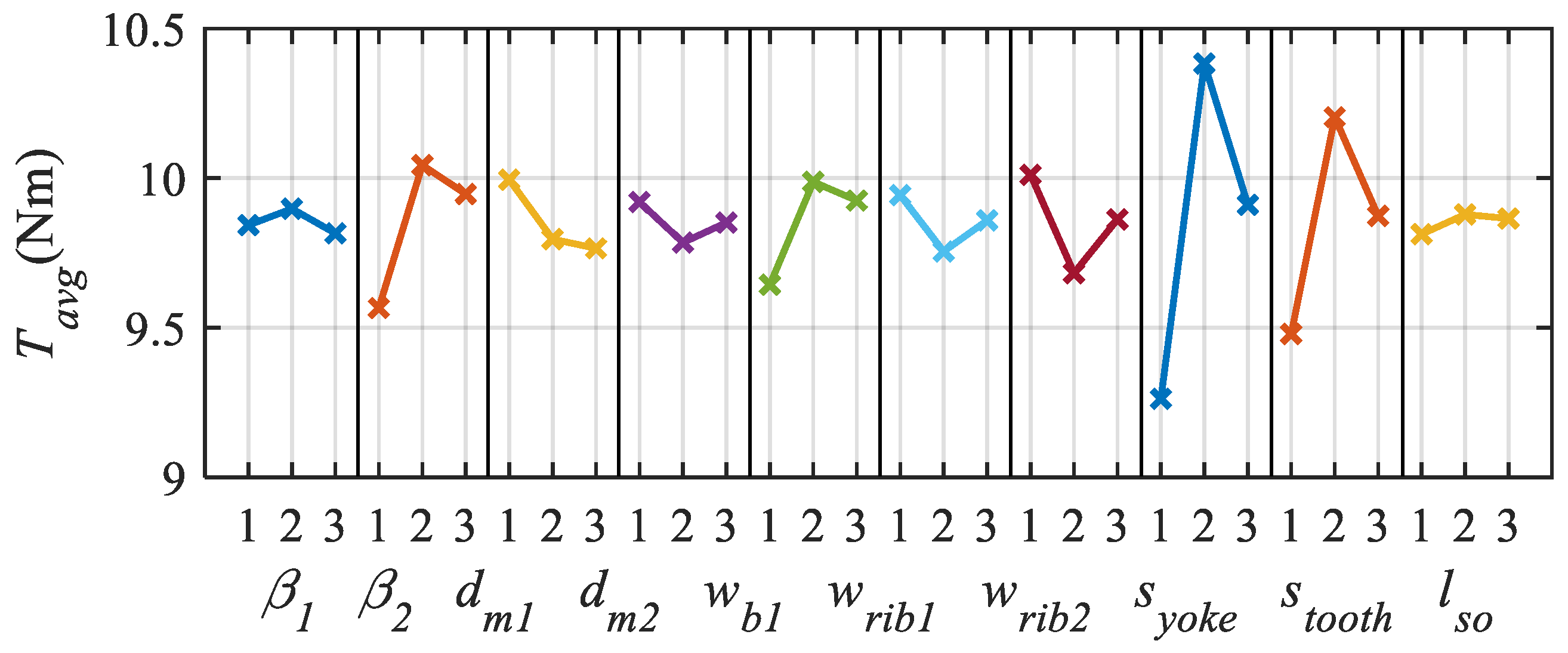
Figure 11,
Figure 12 and
Figure 13 present the output graph for different levels of each parameter. It can be observed that
Tavg is most sensitive to
Syoke and
Stooth, while
Trip is most sensitive to
β2,
wb1 and
Stooth. On the other hand,
wb1 and
Stooth have the greatest influence on
THDU.
Table 5 gives the initial parameters and Taguchi-MEC optimized parameters.
Table 6 compares the
Tavg,
Trip and
THDU. As can be seen, the final results obtained by Taguchi-MEC are very close to those obtained by the multi-object optimization carried out on JMAG. It should be emphasized that the total time needed for Taguchi-MEC is 10 min (including nearly 8 min organizing data), while the time needed for JMAG is nearly 58 h (43,086 elements in mesh and 180 steps in each case). Overall, the proposed Taguchi-MEC method exhibits the great advantage of fast calculation with promising accuracy.
A brief comparison of the proposed 12/4 SynRM with existing state of the art is carried out.
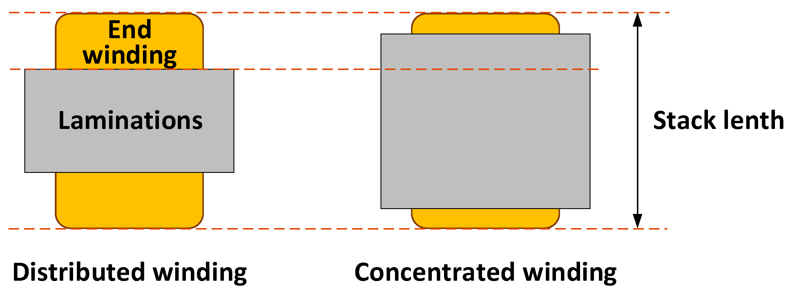
Figure 14 shows the 12/4 SynRM with concentrated winding (CW) and its counterpart, i.e., the 12/4 SynRM with distributed windings (DW). As can be seen, the end winding in the CW machine is much smaller than the DW one; thus, more laminations can be adopted when the same stack length is achieved. A higher copper fill factor and more coil turns are also obtained by the CW machine. More details regarding design specification and electromagnetic performances are given in
Table 7, where the DW SynRM is optimized by a multi-object optimization method carried out on JMAG. The fault tolerant capability is evaluated by the mutual linkage coefficient
kml, which is also given in
Table 7.
where
θ is electrical rotor position. The smaller
kml indicates weaker mutual linkage between armature phases and thus better fault tolerant capability. As can be seen from
Table 7, the proposed 12/4 CW SynRM shows a better torque output result and much better
kml than the traditional 12/4 DW SynRM. The advantage of the torque performances of the CW machine is more obvious when the total stack length is smaller than 95 mm since the proportion of lamination length to total stack length varies with available space in stack.
7. Conclusions
This paper demonstrates the electromagnetic performance of a 12/4 SynRM with concentrated windings. The non-linear MEC model of the 12/4 SynRM is built to get the air-gap flux density, coil flux-linkages, armature winding inductances, etc. The saturation effect is counted in by the MEC. The MEC model is validated by 2D-FEA. Then, the parameter optimization method based on Taguchi and MEC is proposed, aiming at the best average torque, lowest torque ripple and THD in phase voltage. Overall, the proposed Taguchi-MEC method exhibits comparable accuracy with traditional FEA-based multi-object parameter optimization methods, but using much less time. It should be emphasized that the MEC is not used to deal with complex topologies such as a rotor with a non-uniform rotor iron shape or rotor outline. Nevertheless, the proposed MEC-Taguchi method can be employed to obtain a roughly optimized topology that can be used as the initial design to be further optimized by FEA.


