Article

Design, Analysis, and Optimization of Permanent Magnet Vernier Machines Considering Rotor Losses

School of Electrical and Information Engineering, Jiangsu University, Zhenjiang 212013, China
*
Author to whom correspondence should be addressed.
Energies 2022, 15(4), 1502; https://doi.org/10.3390/en15041502
Submission received: 11 January 2022 / Revised: 12 February 2022 / Accepted: 14 February 2022 / Published: 17 February 2022

Abstract

:
The purpose of this paper is the design, analysis, and optimization of a new structure of a permanent magnet vernier machine (PMVM) with a high torque density and low rotor losses. First, the modulation principle and topology of this PMVM is introduced. Then, its average torque and rotor loss are enhanced and reduced by optimizing the flux modulation poles distribution. For the sake of further reducing the rotor losses on the premise of maintaining the torque density, the contribution of the air gap flux density harmonics to the rotor loss is analyzed. Then, a new topological structure of a rotor with a flux barrier is introduced to reduce the rotor losses due to the decrease of each harmful harmonic. Through the analysis of the structure of the PMVM with the flux barrier, the influence of the parameters on the performance is built. After that, a multi-objective optimization algorithm is used to optimize the PMVM so as to obtain the optimal performance. Moreover, the electromagnetic performance comparison between the newly proposed machine and the original one is presented to indicate that lower rotor losses can be obtained by the proposed machine when the torque is ensured. Finally, a prototype of proposed PMVM is built and further tested to verify the validities of the theoretical and finite-element analyses.

1. Introduction

Owing to the merits of high efficiency and torque, the permanent magnet (PM) machine has been widely researched and applied in a lot of fields [1,2,3,4,5,6]. In order to achieve the requirement of a high torque at a low machine size, various high torque density PM machines have been proposed at present, in which a permanent magnet vernier machine (PMVM) as a relatively new machine topology has attracted wide attention because of the characteristics of a simple structure and high torque density [7,8,9,10,11,12,13,14]. In the high torque machine family, PMVM is considered to be a good potential candidate for the field of direct-drive [15,16,17,18].
In recent years, plenty of research has been done on PMVM [19]. The working principle of PMVM was intensely analyzed in [20]. Compared with the conventional PM machine, PMVM obtains a larger torque density because of its special working principle of the so-called magnetic gearing effect. In [21], the effect of salient poles and the modulation principle were further analyzed by the theory magnetic gearing effect. On the other hand, in order to improve the electromagnetic performance of PMVM, a lot of new topologies were proposed. In [22], an advanced PMVM with multiple working harmonics was proposed, where new working harmonics are modulated by introducing the structure of flux modulation poles (FMPs) and thus improving its torque density. In [23,24,25,26], by adopting the doubly PM excited structure in the PMVMs, the amplitudes of multiple working harmonics were further improved. In addition, their torque densities were effectively boosted.
At the same time, there has been extensive research about the optimization of the machines in recent years. The various optimization technologies and the development trend of the machine for its structural size, shape, and topology designs have been discussed in [27]. Moreover, in order to avoid the negative effects of parameters and material tolerances on performance, a robust optimization was utilized in the machine to improve the reliability of the performance. In [28], different designs of experiment methodologies were integrated into encapsuled FEM models using a Digital-Twin-Distiller. Through those methodologies, the tolerances of the machine were analyzed in the process of optimization with a reduction in the computational time. In [29], a PMVM was optimized considering the effect of the manufacturing tolerance. Through the deterministic optimization algorithm and design for the six sigma method, the power factor, torque, and robustness of the PMVM were improved simultaneously.
However, some problems in the design, analysis, and optimization of PMVM need to be solved. Especially noteworthy, abundant harmonics in PMVM can provide a high torque while causing a large electromagnetic loss. Moreover, harmonics with rotation speed and direction have a greatly significant effect on rotor loss [30]. The rotor losses will produce an additional overheat of machine, which may result in a reduction of machine performances and even irreversible demagnetization of PMs. Therefore, rotor loss suppression has become an important direction for developing PMVM. Nowadays, the rotor loss suppression for the conventional PM machine is mainly carried out from the following aspects, such as optimizing the winding structure, segmenting PMs, and changing the stator and rotor structure. In [31], a multilayer winding configuration was adopted for a conventional interior PM machine to reduce stator magnetomotive force (MMF) harmonics, and then the rotor losses could be reduced. Meanwhile, segmenting the PMs is a common method to reduce PM eddy current (EC) loss [32]. However, up until now, the loss analysis and suppression of PMVM was often neglected in previous work. In addition, except for PM segmentation, other rotor loss suppression approaches for the conventional PM machine could not be applied to the PMVM directly. This is likely to be invalid with suppression of the harmonics producing rotor loss due to the multiple working harmonics principle. Consequently, the torque is also significantly reduced with the loss reduction.
In order to solve this problem, the structure of the flux barriers was designed based on the original PMVM. With the desirable suppression effect to the harmful harmonic, the flux barrier design is facilitated to reduce the rotor loss significantly and maintain the torque. Of course, the introduction of the flux barrier structure increases the structural complexity to some extent. In this paper, through the analysis of rotor loss and torque, key parameters of flux barrier and FMP structures on the performance can be determined. Then, a multi-objective optimization algorithm is adopted for PMVM with flux barriers so as to achieve both a high torque density and low rotor loss.
The rest of this paper is organized as follows. The topology of the original PMVM and the modulation principle of the PMVM are introduced in Section 2. The torque of the PMVM is improved by optimizing the FMPs distribution in Section 3. For the sake of further reducing the rotor losses on the premise of maintaining the torque density, the loss component of the PMVM is analyzed in Section 4. Based on this process, a novel topological structure of the rotor is introduced to reduce the rotor losses in Section 5. The function of flux barriers on the armature reaction field is analyzed using a simple analytical model. Then, the flux barriers are designed considering the width and depth. In Section 6, the PMVM with a flux barrier is optimized using an optimization algorithm and is compared with the original PMVM. In Section 7, the electromagnetic performances of the original and proposed PMVMs, such as flux linkage, air-gap flux density, no-load back-EMFs, rotor losses, and torque, are analyzed using the method of finite element analysis (FEA). Section 8 presents the experiments on the prototypes of both machines. Lastly, the conclusions of this paper are made in Section 9.

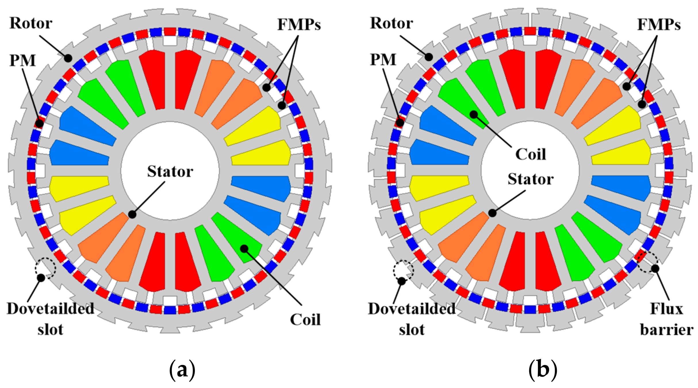
2. Topology and Working Principle

Figure 1 presents the topological structure of the both PMVMs. It can be seen that the machine adopts an outer-rotor structure with 31 pole pairs of PMs evenly distributed on the rotor yoke. There are 20 stator teeth in the stator, and each stator tooth splits into two FMPs. The modulation functions of these FMPs are same as the ferromagnetic pieces in the magnetic gear. Moreover, the winding pattern of the machine adopts the concentrated winding, which effectively reduces the end length of the windings. In addition, compared with the original PMVM structure, the rotor loss of the PMVM is suppressed by the proposed PMVM with the new structure of flux barriers at the rotor yoke.
The operational principle of PMVM is based on the magnetic gearing effect. According to the theory of the magnetic field modulation effect, a new harmonic component is modulated to match the low-order armature harmonic with the high-order PM harmonic. In this way, the magnetic field can change significantly due to the subtle change of the position caused by the rotor rotation, which achieves a high torque density at a low speed. To improve the torque performance by making use of the magnetic gearing effect, the calculation formula between the pole pairs of the armature winding Pa and pole pairs of the rotor Pr and FMPs Pf can be expressed as follows:
P a = P f P r

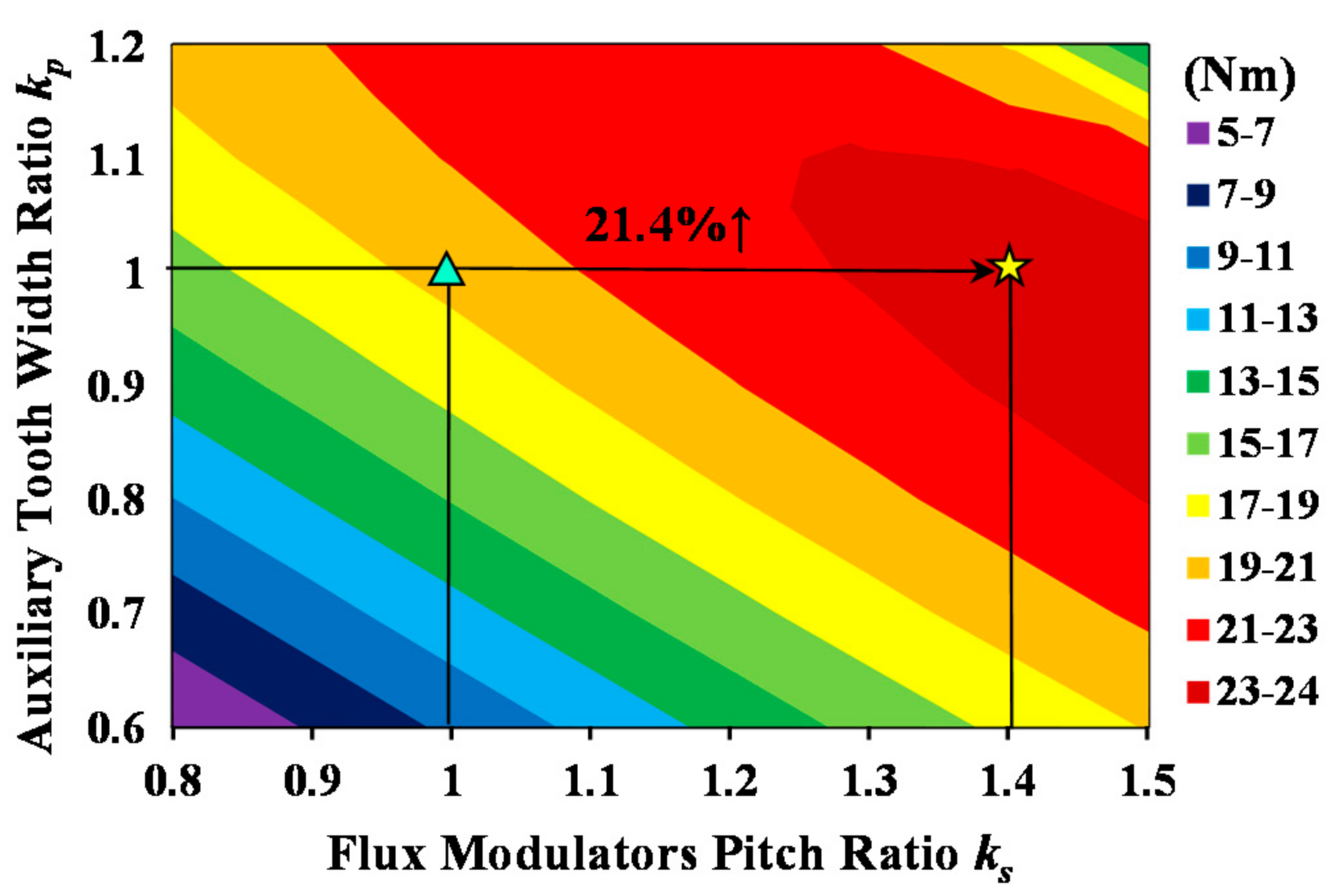
3. Design and Optimization of FMPs

It is worth mentioning that, currently, most PMVMs use uniform distributed FMPs. However, FMPs with different distributions will also have a certain influence on the performance of machine. Figure 2 shows the detailed design parameters for the FMPs, where θ1 (FMP-slot width) represents the width between two FMPs on the same stator tooth and θ2 (FMP width) represents the width of a single FMP. Then, the FMP slot width ratio ks and FMP width ratio kp can be expressed as follows:
k s = θ 1 P f π and k p = θ 2 P f π
When ks + kp = 2, all the FMP-slot widths and slot opening widths are equal, i.e., uniformly distributed FMPs. Conversely, when ks + kp ≠ 2, the width between FMPs will change and become nonuniformly distributed FMPs. With the change of ks and kp, the air-gap field of the machine will change accordingly, which will affect the performance of the machine. Figure 3 and Figure 4 illustrate the average torque and rotor loss variations of the PMVM with ks and kp. As ks and kp increase, the average torque increases at the beginning. However, the average torque begins to decrease when ks and kp exceed a certain range. The average torque is improved by 21.4% at the maximum value compared with the fundamental model (ks = kp = 1). On the other hand, with the increase of ks and kp, the rotor losses present a trend of first increasing and then decreasing. When the average torque reaches its maximum value, the rotor losses decrease by about 10%. Although the optimized PMVM reduces some of the rotor losses by optimizing the FMPs, the remaining rotor losses cannot be further reduced. To ensure the torque density and minimize the losses of PMVM, the factors affecting the loss need to be further investigated and analyzed.

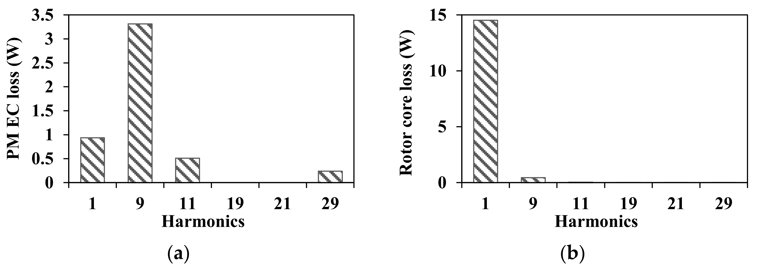
4. Rotor Losses Analysis

It should be noted that after field modulation, a large number of harmonics appear in the PMVM. This could produce large rotor losses, because these harmonics are asynchronous because of the rotation of the rotor. Furthermore, these negative effects are more obvious due to the increase in the armature reaction field. Hence, it is important to analyze the loss of PMVM.
The relationship between EC loss and the parameters of PMs was expressed in [33,34]. The EC loss with regard to the PMs can be achieved as follows:
P e d d y = a b d ω k 2 B P M k 2 σ b 2 24 1 192 π 5 b a n = 0 + tanh 2 n + 1 π a 2 b 2 n + 1 5
where a and b are the height and weight of the PMs, respectively. Moreover, d is the thickness of the PMs. σ and ωk indicate the PM conductivity and the k-th harmonic rotation speed, respectively. BPMk is the amplitude of the k-th harmonic PM flux density. From Equation (3), it can be seen that not only the structural parameters of PMs, but also the harmonic amplitudes of the flux density had a great influence on PM EC loss.
Core loss, which consists of EC loss and hysteresis loss, can be approximately expressed from the flux density of each harmonic, as follows:
P C o r e = k A e f k 2 B C o r e k 2 + A h f k B C o r e k 2
where Ae and fk are the EC loss coefficient and the frequency of different order harmonics, respectively. Ah and BCorek are the coefficient of the hysteresis loss and the k order harmonic amplitude of rotor core flux density, respectively. From Equation (4), it can be seen that the frequency and flux density of each harmonic mainly affect core loss.
Because of the principle of the modulation effect, the harmonic components generated by PMs can be expressed as follows
P p m i , j = i P r ± j N s
where i = 1, 3, 5, …, j = 0, 1, 2, …. It can be inferred that the working harmonics of the machine are the 9th, 11th, 29th, 31st, etc. Figure 5 and Figure 6 show the no-load and armature reaction air-gap flux density, respectively. This reveals that the harmonic components generated by the PM field were 9th, 11th, 29th, and 31st orders, while in addition to these harmonics, the armature reaction field also had 1st, 19th, and 21st order harmonics. Meanwhile, the 31st harmonic which mainly caused by the fundamental MMF move synchronously with the rotor, which is a static harmonic and does not produce losses. Figure 7 shows the on-load machine rotor losses of the original PMVM, including PM EC loss and rotor core loss under the on-load situation. This indicates that the PM EC loss corresponding to the 9th harmonic reached the peak value, while 1st harmonic was the second largest value. The PM EC loss with regard to the 1st harmonic occupied about 22% of the whole PM EC loss. In addition, the rotor core loss was mainly determined by the 1st harmonic, which occupied nearly 96% of the total rotor core loss. In summary, it was found that the 1st harmonic has a huge influence on rotor losses. On the other hand, the 1st harmonic was found to be a non-working harmonic that has no effect on torque. Therefore, through reducing the 1st harmonic, the rotor losses could be reduced while maintaining the torque density.

5. Low Rotor Loss Design

In order to effectively depress the 1st armature harmonic, a new rotor structure of flux barriers is introduced in PMVM. Flux barriers with a suitable size and position are placed at the rotor yoke. Figure 8 shows the detailed design parameters for the flux barriers, where wfb represents the width of a single flux barrier and dfb represents the depth of a single flux barrier.

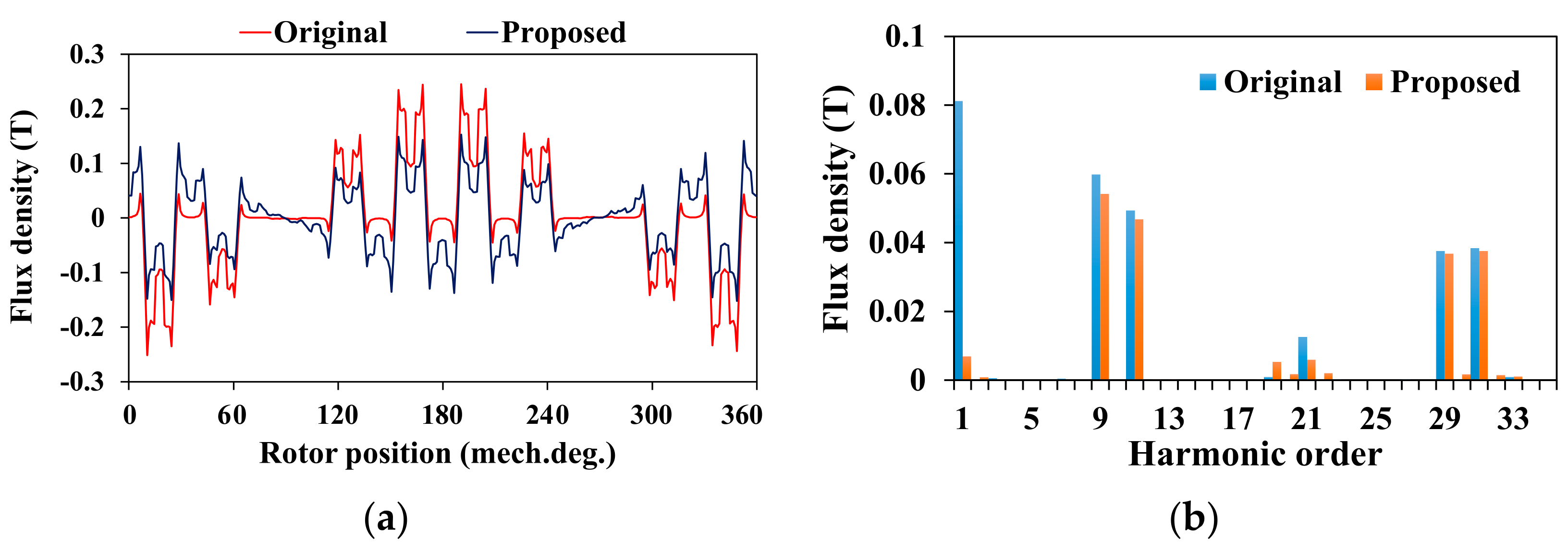
5.1. Analysis of Armature Reaction Field

The armature reaction field is analyzed by a simple analysis model, as shown in Figure 9.
Accordingly, the rotor permeance of the original PMVM and the proposed one can be expressed as
Λ o r θ = Λ 1
Λ p r θ = Λ 1 Λ 1 Λ 2 λ T m = 1 2 Λ 1 Λ 2 m π sin m π λ T cos m P r θ
where Λ1 and Λ2 are the Fourier coefficients, and λ/T is ratio of flux barrier thickness with regard to the rotor yoke thickness. It is worth noting that the abbreviations of or and pr represent the original and proposed machines, respectively.
The armature reaction MMF of the PMVM can be expressed as
F a q θ , t = 10 F q N I max q π q cos q θ ± ω t
where Fq is the Fourier coefficient, N is the number of turns per phase, Imax is the maximum value of armature current, and q = 10r ± 1, r = 0, 1, 2….
Then, through multiplying the armature reaction MMF and original rotor permeance, the original flux density in the armature flux field can be obtained as follows:
B o r θ , t = 10 F q N I max q π Λ 1 q cos q θ ± ω t
Meanwhile, the proposed flux density of the armature reaction can be expressed as
B p r θ , t = 10 F q N I max q π Λ 1 Λ 1 Λ 2 λ T q cos q θ ± ω t 10 F q N I max q π 2 Λ 1 Λ 2 sin m π λ T q m = 1 cos q + m P r θ ± ω t 10 F q N I max q π 2 Λ 1 Λ 2 sin m π λ T q m = 1 cos q m P r θ ± ω t
Comparing Equations (9) and (10), it can be found that the amplitude of the armature reaction flux density will decrease due to the effect of the flux barrier, hence suppressing the rotor loss of the machine to some extent. On the other hand, due to the function of field modulation by flux barrier, q + mPr and qmPr order harmonics are introduced. Figure 10 shows the amplitude variation of q order armature harmonic corresponding to the change of the flux barrier width. From this figure, the amplitude of the 1st harmonic significantly decreases because of the increase in the width of the flux barriers. According to Equations (3) and (4), the loss caused by the 1st harmonic will be greatly reduced. On the other hand, the 31st working harmonic mainly affecting the torque component nearly has no change. Therefore, the torque of PMVM can be maintained and the rotor losses can be lowered.

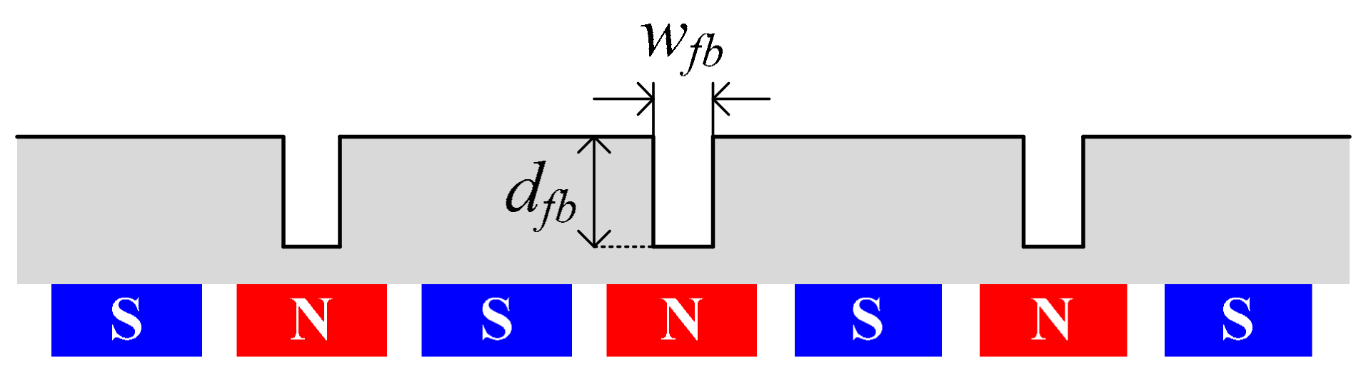
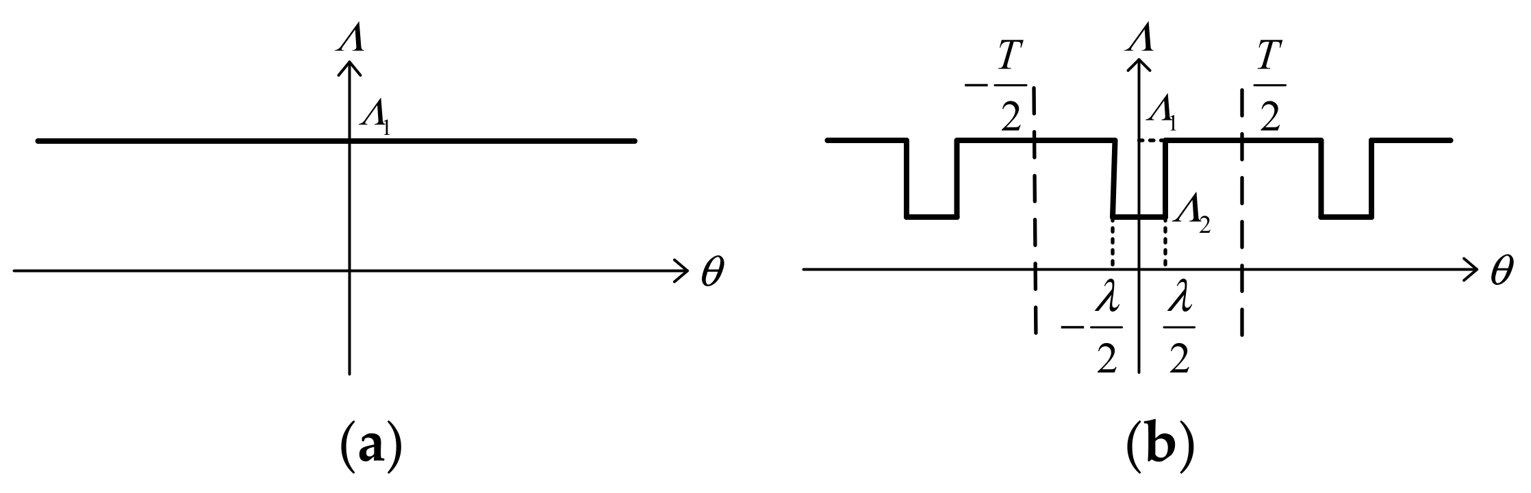
5.2. Design of Flux Barriers

The armature reaction will produce some useless low order harmonics, which increase the losses of the machine. These low order harmonics, especially the 1st harmonic produced by the armature reaction, can be effectively suppressed by adopting flux barrier design. Meanwhile, it will not have a significant influence on high order working harmonics, which ensures the torque density. In order to maintain torque density and reduce rotor losses as much as possible, it is very important to choose appropriate flux barriers. Figure 10 and Figure 11 illustrate the average torque and rotor loss variations of PMVM with the flux barrier width wfb and flux barrier depth dfb. As wfb and dfb increase, the average torque also increases at the beginning. Then, the average torque begins to decrease when wfb and dfb exceed a certain range. On the other hand, with the increase in wfb and dfb, the rotor losses are significantly reduced.

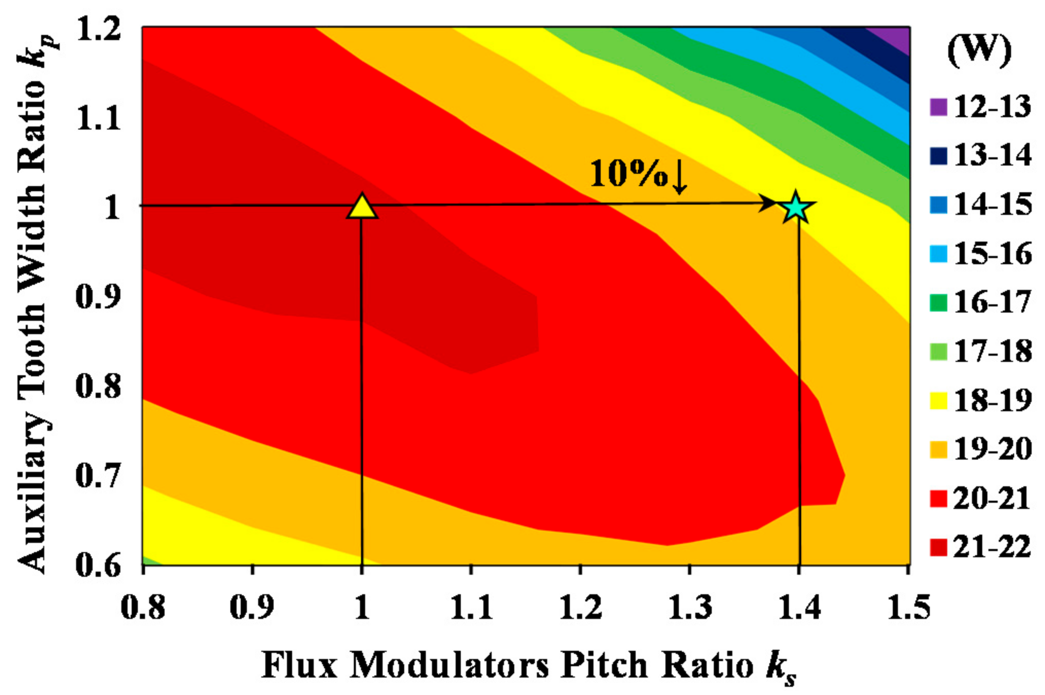
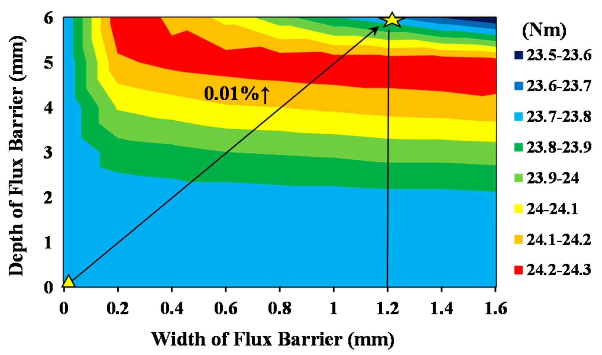
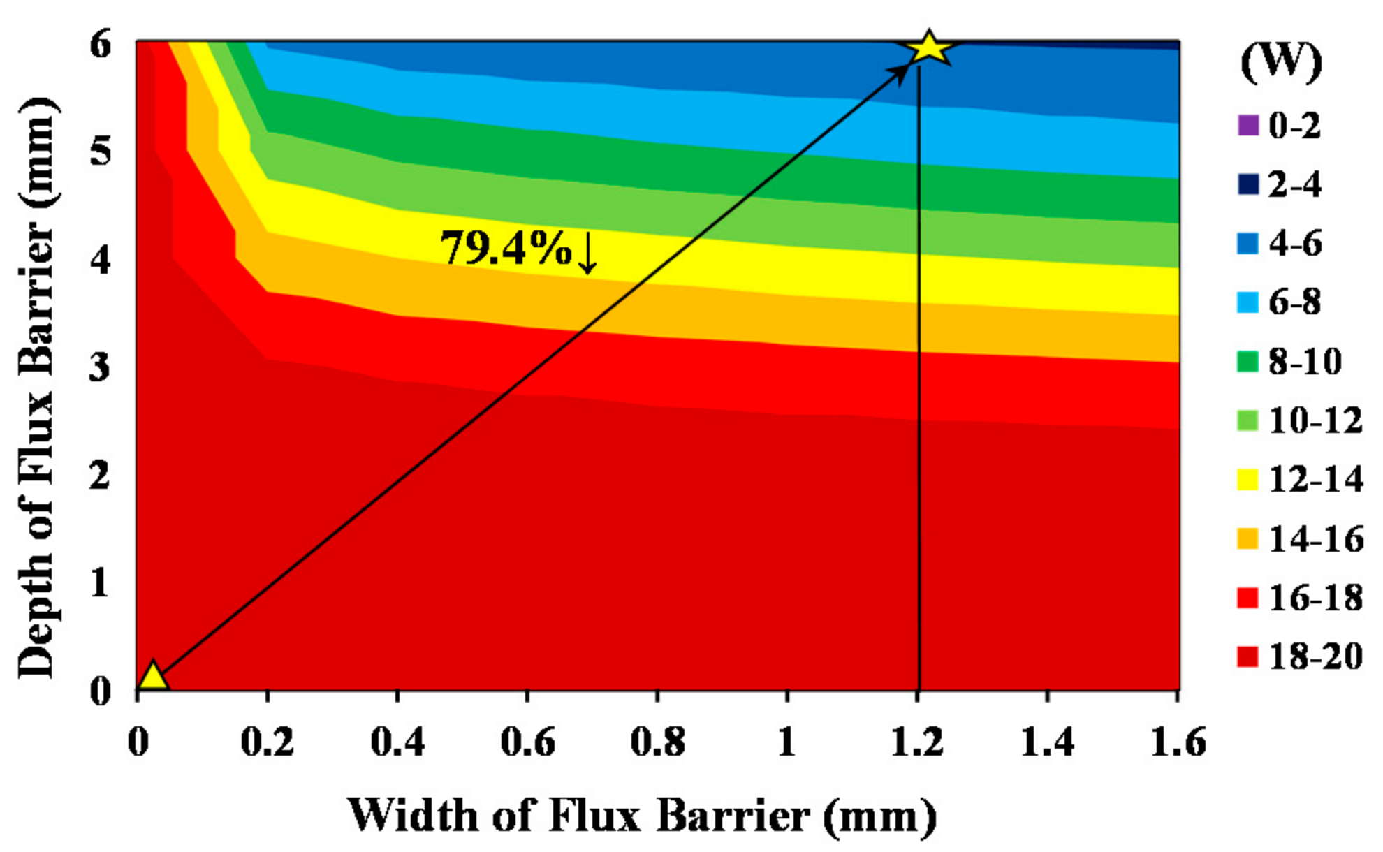
6. Performance Optimization

Through the above-mentioned design and analysis of the PMVM structure, it can be seen that the FMP slot width ratio ks, FMP width ratio kp, the flux barrier width wfb, and the flux barrier depth dfb influenced the performance of PMVM. In order to obtain the optimal torque and rotor loss, a multi-objective optimization non-dominated sorting genetic algorithm II (NSGA-II) was used to optimize the torque and rotor loss. Figure 12 shows the Pareto frontiers of PMVM with flux barriers and original PMVM using this optimization method. It can be seen that all the Pareto design points with regard to the PMVM with flux barrier present lower rotor loss than the original PMVM. In order to obtain minimal rotor loss, the green points were selected as the optimization results to conduct further research. The torque and rotor loss of the selected optimal PMVM with flux barriers were 23.72 Nm and 0.6 W, respectively. Therefore, the parameters ks and kp were finally chosen as 1.4 and 1.0, respectively, and wfb and dfb were finally determined to be 1.2 mm and 6 mm, respectively. Compared with the 23.69 Nm torque and 15 W rotor loss of the original machine, the rotor losses of the proposed machine with flux barriers were reduced significantly, while the torque was basically unchanged.

7. Performance Evaluation

The electromagnetic performances of both PMVMs are compared comprehensively by FEA in this section. The results reveal that lower rotor losses could be obtained by the proposed machine without sacrificing the torque density, which verifies the above theoretical analysis.

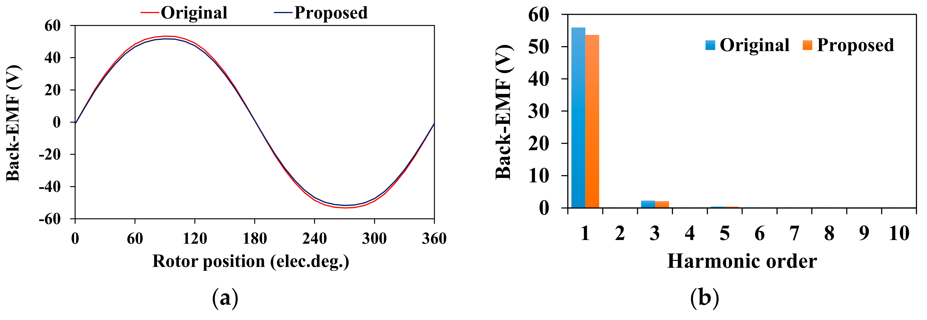
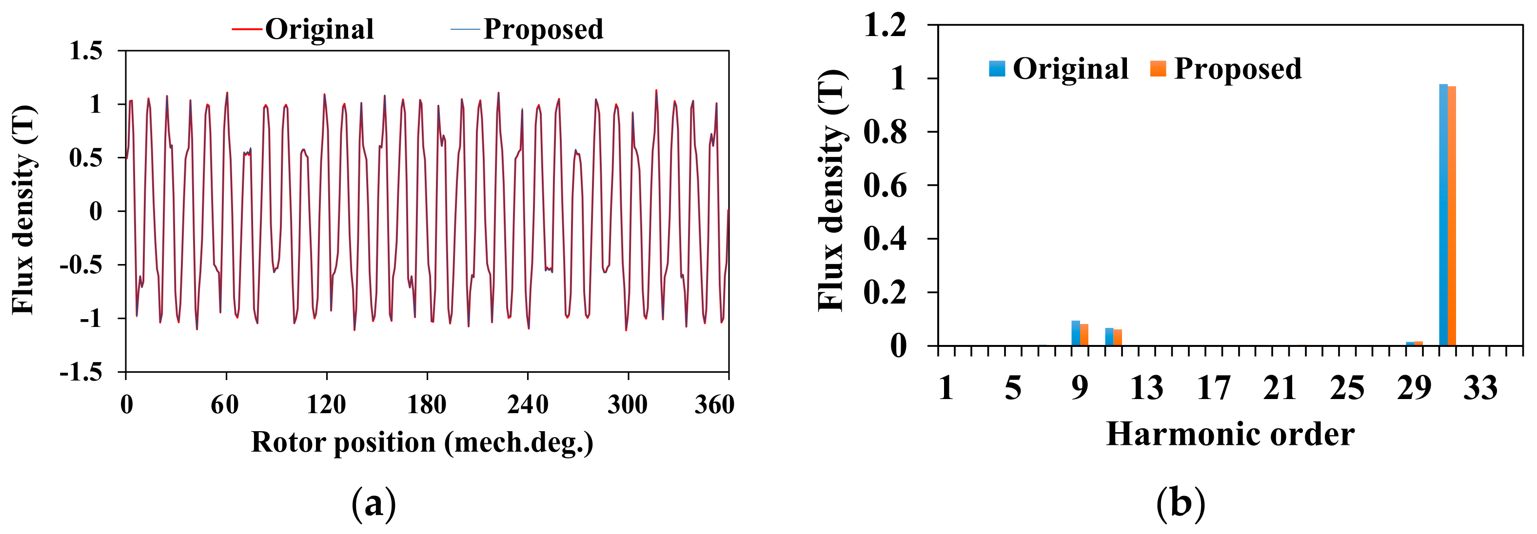
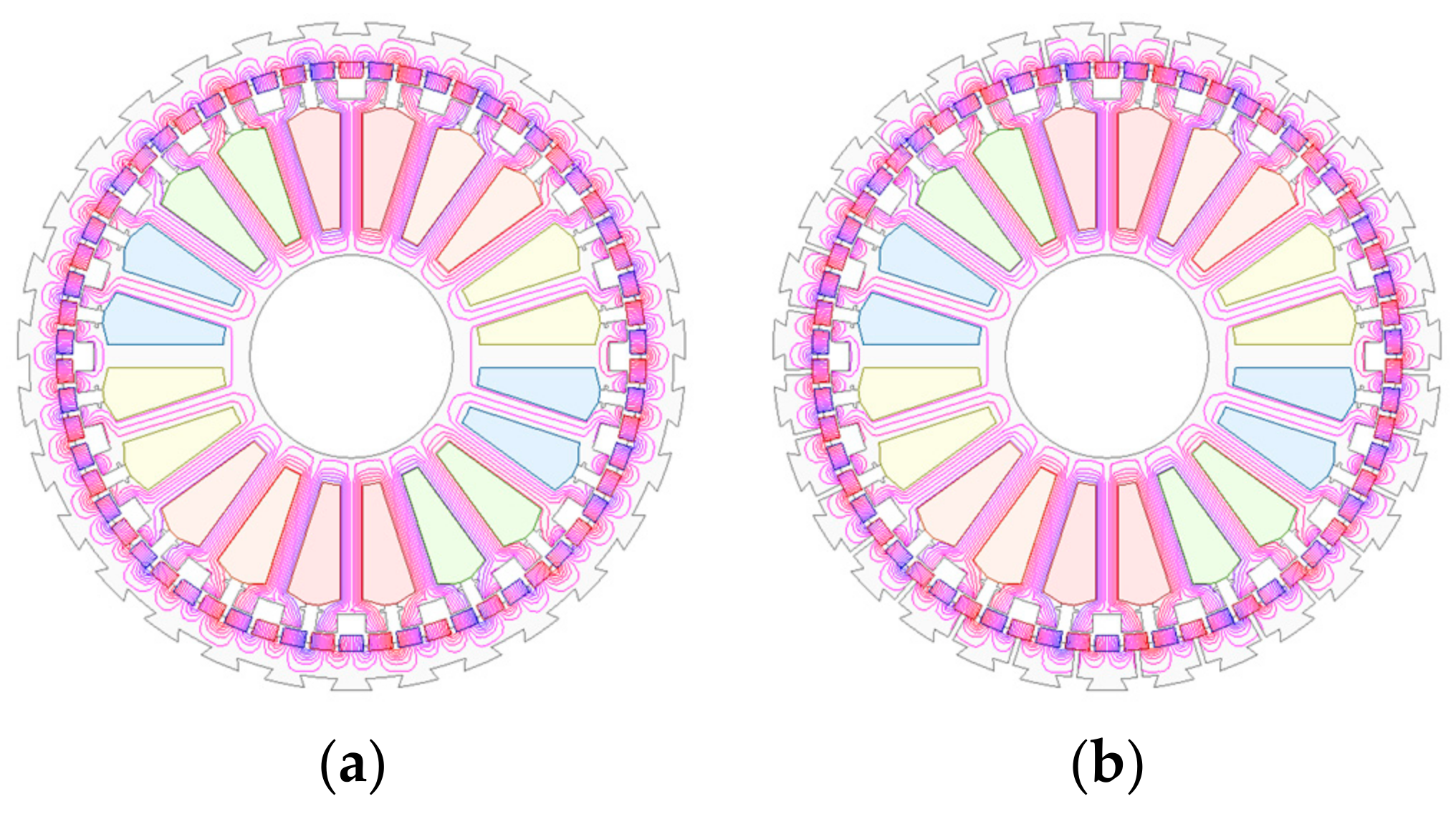
7.1. Open-Circuit Characteristics

Figure 13 presents the no-load magnetic field distributions of the original PMVM and proposed PMVM. It can be seen that the magnetic field distributions were almost same between the two machines. This phenomenon means that the PM magnetic field was not influenced by flux barriers with an appropriate position and size. The no-load back-EMF waveforms are illustrated in Figure 14. It can be observed that the flux barrier design had little effect on the no-load back-EMFs.
Figure 15 makes a comparison between the no-load flux density waveform and harmonic spectrum of the PMVMs. It can be seen that the waveform and spectrum of the air-gap flux density of the proposed machine were basically coincident with the original one. The new rotor topology had only a slight influence on the PM field, which indicates that the torque performance of the proposed machine will not degrade.

7.2. Armature Reaction Characteristics
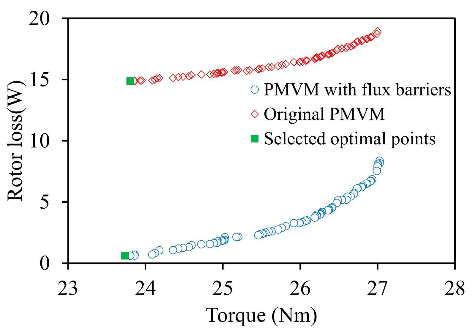
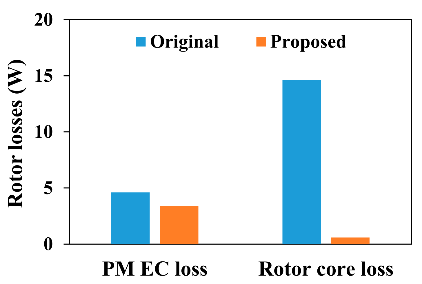
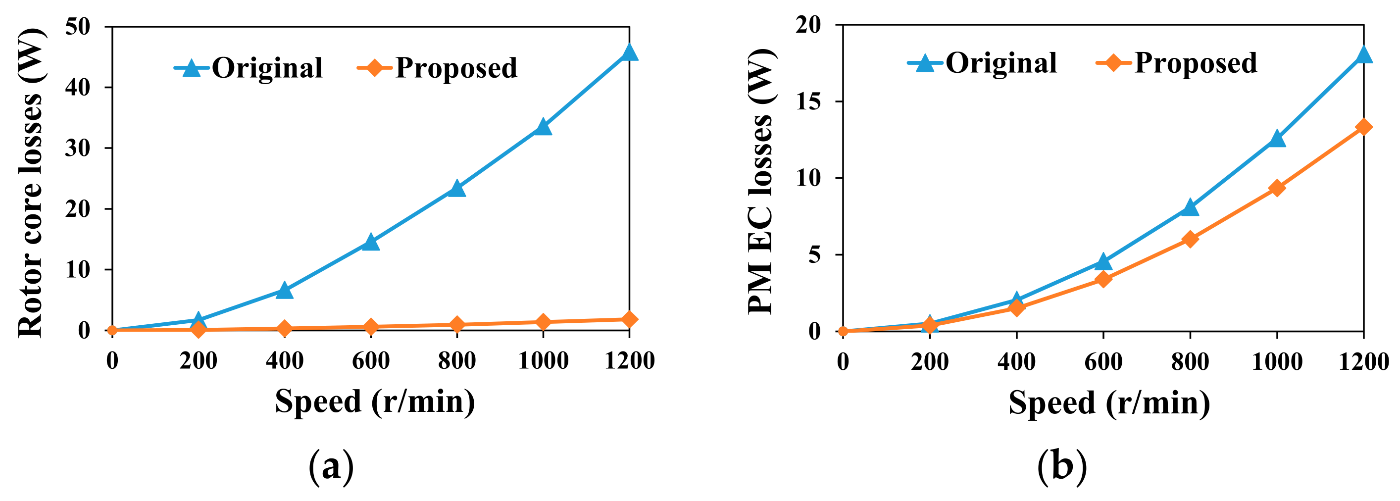
Figure 16 depicts the armature reaction magnetic field nephogram. As shown, the proposed machine obtained greater strength for the armature magnetic field than the original one. Figure 17 shows the flux density waveforms of the armature reaction and harmonics of the two PMVMs. As can be seen, the 1st harmonic had a significant decline, while the higher working harmonics were not greatly affected. The obvious weakening of the 1st harmonic from the magnetic field distribution can be seen in Figure 16b. At the same time, some new modulation harmonics could be produced by the flux barriers (such as the 20th and 22th order). It is worth mentioning that if the core saturation was high, the torque of the PMVM would be limited. Through the new proposed flux barrier in the rotor, the core saturation could be significantly reduced, which increased the torque capacity of the machine. As a result, although the back-EMF of the machine shown in Figure 14 decreased slightly, the torque of the machine could improve to a certain extent.

7.3. Rotor Losses

Figure 18 shows the rotor losses by FEA. From Figure 18, the proposed machine obtained much lower rotor losses than the original machine. The PM EC loss decreased by 26% while the rotor core loss of the proposed machine was also reduced by 96%. Figure 19 depicts the variation of the rotor losses versus rotor speed of both machines. As observed, with increasing the rotor speed, the increase of rotor core loss of the original machine was much higher than that of the proposed one. Meanwhile, with increasing the rotor speed, the increment of PM EC loss of the original PMVM was larger than that of the proposed one. Thus, the proposed machine could offer a much lower rotor loss when increasing the rotor speed.

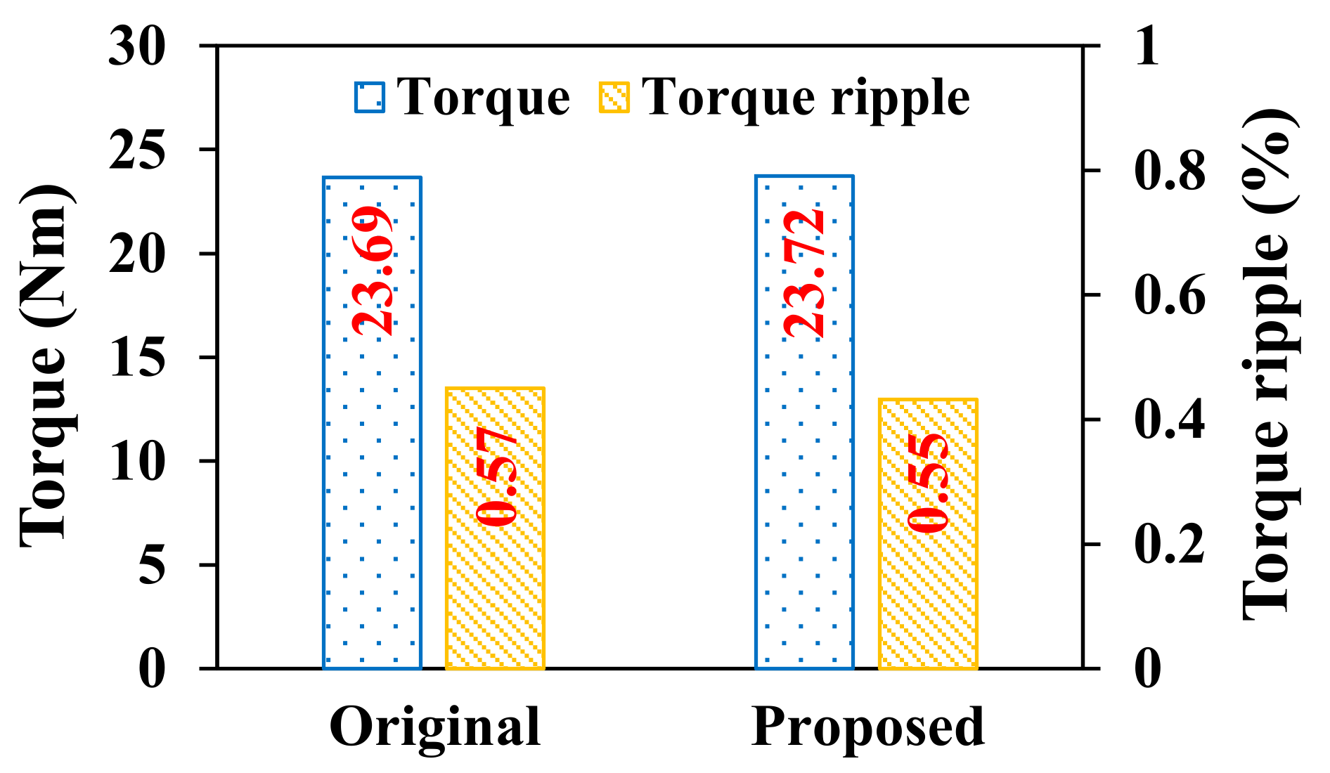
7.4. Torque Capacity

The average torque and torque pulsation are shown in Figure 20. It can be seen that both the original and proposed PMVM had a high torque and low torque ripple, which is an advantage of PMVM. Meanwhile, the average torque and torque ripple of both PMVMs was basically unchanged. These results prove the correctness of the preceding analysis.

8. Experimental Validation

Based on the above analysis, a new PMVM with low rotor losses was built. The new proposed PMVM could significantly reduce rotor losses, while maintaining the torque density. To verify the effectiveness of the analysis results through the experiment, the original and proposed PMVMs were manufactured and tested, respectively. The prototypes for both PMVMs were manufactured as shown in Figure 21.
Throughout the measurements, the no-load back-EMFs of the original and proposed machines were tested at 600 r/min, as shown in Figure 22. It can be seen that the differences between the measured and FEA results of the original and proposed PMVMs were lower than 6%. The differences were mainly due to experimental errors. In addition, the amplitude of the no-load back-EMF of both machines was basically unchanged, and the waveforms were approximately sinusoidal. This also verified the consistency of the machine performance between the simulation and experiment by introducing the flux barriers in the proposed machine.

9. Conclusions

In this paper, a new PMVM with a high torque density and low rotor losses is proposed. First of all, this paper introduces the topological structure and working principle of PMVM. Then, the torque of PMVM is effectively enhanced by optimizing the parameters of FMPs. To reduce rotor losses, the loss component of PMVM is analyzed. The results show that the first harmonic causes rotor losses while having no effect on the average torque. Therefore, the 1st harmonic is considered to be reduced in order to maintain the torque and reduce the rotor loss. Based on this process, a new rotor structure with flux barriers is designed. The influence of the flux barriers on the first harmonic is revealed. It is found that with appropriate flux barrier design, the first harmonic produced by the armature reaction field can be greatly reduced and the reduction of working harmonics is slight. As a result, the rotor losses are effectively reduced while maintaining the torque density. Furthermore, the proposed and original PMVMs are compared by FEA. Finally, the two PMVMs are fabricated and final test results verify the effectives of the theoretical analysis and FEA results.

Author Contributions

Conceptualization, L.X.; manufacturing, W.W. and L.X.; software, W.W. and B.L.; validation; B.L. and L.X.; writing—original draft preparation, W.W.; writing—review and editing, L.X.; supervision, L.X. All authors have read and agreed to the published version of the manuscript.

Funding

This work was supported in part by the National Natural Science Foundation of China (52177044), the Hong Kong Scholars Program (XJ2019031), the Natural Science Foundation of Jiangsu Higher Education Institutions (21KJA470004), and the Priority Academic Program Development of Jiangsu Higher Education Institutions.

Institutional Review Board Statement

Not applicable.

Informed Consent Statement

Not applicable.

Data Availability Statement

Not applicable.

Conflicts of Interest

The authors declare no conflict of interest.

References

  1. Li, X.; Xue, Z.; Yan, X.; Zhang, L.; Ma, W.; Hua, W. Low-complexity multivector-based model predictive torque control for PMSM with voltage preselection. IEEE Trans. Power Electron. 2021, 36, 11726–11738. [Google Scholar] [CrossRef]
  2. Wang, B.; Wang, J.; Griffo, A.; Sen, B. Experimental Assessments of a Triple Redundant Nine-Phase Fault-Tolerant PMA SynRM Drive. IEEE Trans. Ind. Electron. 2019, 66, 772–783. [Google Scholar] [CrossRef] [Green Version]
  3. Li, X.; Xue, Z.; Zhang, L.; Hua, W. A low-complexity three-vector-based model predictive torque control for SPMSM. IEEE Trans. Power Electron. 2021, 36, 13002–13012. [Google Scholar] [CrossRef]
  4. Chen, Q.; Xu, G.; Zhai, F.; Liu, G. A novel spoke-type PM motor with auxiliary salient poles for low torque pulsation. IEEE Trans. Ind. Electron. 2020, 67, 4762–4773. [Google Scholar] [CrossRef]
  5. Jiang, T.; Zhao, W.; Xu, L.; Ji, J. A novel parallel hybrid excitation field modulated machine with efficient utilization of multiworking harmonics. IEEE Trans. Ind. Electron. 2020, 69, 1177–1188. [Google Scholar] [CrossRef]
  6. Zhang, G.; Hua, W.; Han, P. Quantitative Evaluation of the Topologies and Electromagnetic Performances of Dual-Three-Phase Flux-Switching Machines. IEEE Trans. Ind. Electron. 2018, 65, 9157–9167. [Google Scholar] [CrossRef]
  7. Xu, L.; Liu, G.; Zhao, W.; Yang, X.; Cheng, R. Hybrid stator design of fault-tolerant permanent-magnet vernier machines for direct-drive applications. IEEE Trans. Ind. Electron. 2017, 64, 179–190. [Google Scholar] [CrossRef]
  8. Zhao, X.; Niu, S. Design of a novel parallel-hybrid-excited vernier reluctance machine with improved utilization of redundant winding harmonics. IEEE Trans. Ind. Electron. 2018, 65, 9056–9067. [Google Scholar] [CrossRef]
  9. Jiang, S.; Liu, G.; Zhao, W.; Xu, L.; Chen, Q. Modeling and analysis of spoke-type permanent magnet vernier machine based on equivalent magnetic network method. Chin. J. Elect. Eng. 2018, 4, 96–103. [Google Scholar]
  10. Shi, Y.; Jian, L. A novel dual-permanent-magnet-excited machine with flux strengthening effect for low-speed large-torque applications. Energies 2018, 11, 158. [Google Scholar] [CrossRef] [Green Version]
  11. Jang, D.; Chang, J. Investigation of doubly salient structure for permanent magnet vernier machines using flux modulation effects. IEEE Trans. Energy Convers. 2019, 34, 2019–2028. [Google Scholar] [CrossRef]
  12. Xu, L.; Wu, W.; Zhao, W. Airgap magnetic field harmonic synergetic optimization approach for power factor improvement of PM vernier machines. IEEE Trans. Ind. Electron. [CrossRef]
  13. Du, K.; Xu, L.; Zhao, W.; Liu, G. Analysis and Design of a Fault-Tolerant Permanent Magnet Vernier Machine With Improved Power Factor. IEEE Trans. Ind. Electron. 2022, 69, 4353–4363. [Google Scholar] [CrossRef]
  14. Li, X.; Chau, K.; Cheng, M. Analysis design and experimental verification of a field-modulated permanent-magnet machine for direct-drive wind turbines. IET Electr. Power Appl. 2015, 9, 150–159. [Google Scholar] [CrossRef]
  15. Xu, L.; Zhao, W.; Liu, G.; Song, C. Design optimization of a spoke-type permanent-magnet vernier machine for torque density and power factor improvement. IEEE Trans. Veh. Technol. 2019, 68, 3446–3456. [Google Scholar] [CrossRef]
  16. Tlali, P.; Wang, R.; Gerber, S.; Botha, C.; Kamper, M. Design and performance comparison of vernier and conventional PM synchronous wind generators. IEEE Trans. Ind. Appl. 2020, 56, 2570–2579. [Google Scholar] [CrossRef]
  17. Raihan, M.; Baker, N.; Smith, K.; Almoraya, A. Development and testing of a novel cylindrical permanent magnet linear generator. IEEE Trans. Ind. Appl. 2020, 56, 3668–3678. [Google Scholar] [CrossRef]
  18. Kwon, J.; Kwon, B. Investigation of dual-stator spoke-type vernier machine for EV application. IEEE Trans. Magn. 2018, 54, 1–5. [Google Scholar] [CrossRef]
  19. Wu, F.; Refaie, A. Permanent magnet vernier machines: A review. IET Electr. Power Appl. 2019, 13, 127–137. [Google Scholar] [CrossRef]
  20. Kim, B.; Lipo, T. Operation and design principles of a PM vernier motor. IEEE Trans. Ind. Appl. 2014, 50, 3656–3663. [Google Scholar] [CrossRef]
  21. Cheng, M.; Wei, H.; Han, P.; Feng, X. Analysis of airgap field modulation principle of simple salient poles. IEEE Trans. Ind. Electron. 2019, 66, 2628–2638. [Google Scholar] [CrossRef]
  22. Zou, T.; Li, D.; Qu, R.; Jiang, D.; Li, J. Advanced high torque density PM vernier machine with multiple working harmonics. IEEE Trans. Ind. Appl. 2017, 53, 5295–5304. [Google Scholar] [CrossRef]
  23. Wang, Q.; Niu, S.; Yang, L. Design optimization and comparative study of novel dual-PM excited machines. IEEE Trans. Ind. Electron. 2017, 64, 9924–9933. [Google Scholar] [CrossRef]
  24. Lin, Q.; Niu, S.; Fu, W. Design and optimization of a dual-permanent-magnet vernier machine with a novel optimization model. IEEE Trans. Magn. 2020, 6, 1–5. [Google Scholar] [CrossRef]
  25. Xu, L.; Zhao, W.; Liu, G.; Ji, J.; Niu, S. A novel dual-permanent-magnet-excited machine with non-uniformly distributed permanent-magnets and flux modulation poles on the stator. IEEE Trans. Veh. Technol. 2020, 69, 7104–7115. [Google Scholar] [CrossRef]
  26. Gao, Y.; Doppelbauer, M.; Qu, R.; Li, D.; Ding, H. Synthesis of a flux modulation machine with permanent magnets on both stator and rotor. IEEE Trans. Ind. Appl. 2021, 57, 294–305. [Google Scholar] [CrossRef]
  27. Bramerdorfer, G.; Tapia, J.; Pyrhonen, J.; Cavagnino, A. Modern Electrical Machine Design Optimization: Techniques, Trends, and Best Practices. IEEE Trans. Ind. Electron. 2018, 65, 7672–7684. [Google Scholar] [CrossRef]
  28. Orosz, T.; Gadó, K.; Katona, M.; Rassõlkin, A. Automatic Tolerance Analysis of Permanent Magnet Machines with Encapsuled FEM Models Using Digital-Twin-Distiller. Processes 2021, 9, 2077. [Google Scholar]
  29. Xu, L.; Wu, W.; Zhao, W.; Liu, G.; Niu, S. Robust design and optimization for a permanent magnet vernier machine with hy-brid stator. IEEE Trans. Energy Convers. 2020, 9, 2086–2094. [Google Scholar] [CrossRef]
  30. Xu, L.; Zhao, W.; Wu, M.; Ji, J. Investigation of slot–pole combination of dual-permanent-magnet-excited vernier machines by using air-gap field modulation theory. IEEE Trans. Transport. Electrif. 2019, 5, 1360–1369. [Google Scholar] [CrossRef]
  31. Abdel-Khalik, A.; Ahmed, S.; Massoud, A. Effect of multilayer windings with different stator winding connections on interior PM machines for EV applications. IEEE Trans. Magn. 2016, 52, 1–7. [Google Scholar] [CrossRef]
  32. Ji, J.; Luo, J.; Zhao, W.; Zheng, J.; Zhang, Y. Effect of circumferential segmentation of permanent magnets on rotor loss in fractional-slot concentrated-winding machines. IET Electr. Power Appl. 2017, 11, 151–159. [Google Scholar] [CrossRef]
  33. Cheng, M.; Zhu, S. Calculation of PM eddy current loss in IPM machine under PWM VSI supply with combined 2-D FE and analytical method. IEEE Trans. Magn. 2017, 53, 1–12. [Google Scholar] [CrossRef]
  34. Xu, L.; Zhao, W.; Li, R.; Niu, S. Analysis of rotor losses in permanent magnet vernier machines. IEEE Trans. Ind. Electron. 2018, 69, 1224–1234. [Google Scholar] [CrossRef]
Figure 1. Topology of the original PMVM: (a) original and (b) proposed.
Energies 15 01502 g001
Figure 2. Detailed design parameters for FMPs.
Energies 15 01502 g002
Figure 3. Variation of average torque with ks and kp in PMVM.
Energies 15 01502 g003
Figure 4. Variation of rotor losses with ks and kp in PMVM.
Energies 15 01502 g004
Figure 5. No-load flux density harmonics distribution of PMVM: (a) waveform and (b) spectrum.
Energies 15 01502 g005
Figure 6. Armature reaction flux density harmonics distribution of PMVM: (a) waveform and (b) spectrum.
Energies 15 01502 g006
Figure 7. The result of rotor losses in the original PMVM: (a) PM EC loss and (b) rotor core loss.
Energies 15 01502 g007
Figure 8. Detailed design parameters for flux barriers.
Energies 15 01502 g008
Figure 9. Simple rotor permeance model for the armature reaction field analysis: (a) original and (b) proposed.
Energies 15 01502 g009
Figure 10. Variation of average torque with wfb and dfb in the proposed PMVM.
Energies 15 01502 g010
Figure 11. Variation of rotor losses with wfb and dfb in the proposed PMVM.
Energies 15 01502 g011
Figure 12. Pareto design frontiers calculated by NSGA-II.
Energies 15 01502 g012
Figure 13. Magnetic field distributions of both PMVMs in open-circuit operation: (a) original and (b) proposed.
Energies 15 01502 g013
Figure 14. Phase open-circuit back-EMFs of both PMVMs: (a) waveform and (b) spectrum.
Energies 15 01502 g014
Figure 15. Comparison of the open-circuit flux density of both PMVMs: (a) waveform and (b) spectrum.
Energies 15 01502 g015
Figure 16. Comparison of the armature reaction field nephogram: (a) color scale, (b) original, and (c) proposed.
Energies 15 01502 g016
Figure 17. Comparison of the flux density of two PMVMs in the armature reaction: (a) waveform and (b) scheme.
Energies 15 01502 g017
Figure 18. Comparison of the rotor losses between the original and proposed machines.
Energies 15 01502 g018
Figure 19. Rotor losses with the rotor speed of both machines: (a) rotor core loss and (b) PM EC loss.
Energies 15 01502 g019
Figure 20. Average torque and torque pulsation of both PMVMs.
Energies 15 01502 g020
Figure 21. Prototype machines: (a) stator, (b) original rotor, and (c) new rotor with flux barriers.
Energies 15 01502 g021
Figure 22. FEA and measured back EMFs of the original and proposed PMVMs.
Energies 15 01502 g022
Publisher’s Note: MDPI stays neutral with regard to jurisdictional claims in published maps and institutional affiliations.

