Article

Implementation and Test of an IEC 61850-Based Automation Framework for the Automated Data Model Integration of DES (ADMID) into DSO SCADA

Smart Grid Research Group, Ulm University of Applied Sciences, 89081 Ulm, Germany
*
Author to whom correspondence should be addressed.
Former researchers of the Smart Grid Research Group.
Energies 2022, 15(4), 1552; https://doi.org/10.3390/en15041552
Submission received: 10 January 2022 / Revised: 8 February 2022 / Accepted: 15 February 2022 / Published: 19 February 2022
(This article belongs to the Special Issue Design and Validation of Smart Energy System Concepts and Methods)

Abstract

:
As a result of the energy transition, an increasing number of Decentralized Energy Systems (DES) will be installed in the distribution grid in the future. Accordingly, new methods to systematically integrate the growing DES in distribution power systems must be developed utilizing the constantly evolving Information and Communication Technologies (ICT). This paper proposes the Automated Data Model Integration of DES (ADMID) approach for the integration of DES into the ICT environment of the Distribution System Operator (DSO). The proposed ADMID utilizes the data model structure defined by the standard-series IEC 61850 and has been implemented as a Python package. The presented two Use Cases focus on the Supervisory Control and Data Acquisition (SCADA) on the DSO operational level following a four-stage test procedure, while this approach has enormous potential for advanced DSO applications. The test results obtained during simulation or real-time communication to field devices indicate that the utilization of IEC 61850-compliant data models is eligible for the proposed automation approach, and the implemented framework can be a considerable solution for the system integration in future distribution grids with a high share of DES. As a proof-of-concept study, the proposed ADMID approach requires additional development with a focus on the harmonization with the Common Information Model (CIM), which could significantly improve its functional interoperability and help it reach a higher Technology Readiness Level (TRL).

1. Introduction

The energy transition is currently playing an important role in the fight against global warming. To reduce CO2 emissions systematically, various new technologies must be developed and implemented. The energy supply branch—as a major producer of CO2—is supposed to pioneer an evolutionary technical breakthrough; this includes stimulating the growth of Renewable Energy Systems (RES), Electric Vehicles (EV), Electric Charging Points (ECP), Battery Energy Storage Systems (BESS), Combined Heat and Power (CHP) and various other types of Decentralized Energy Resources (DER) [1]. These devices and energy systems can be defined by a new term: Decentralized Energy Systems (DES).
Up to now, the distribution grid planning and operation is based on a well-known load characteristic described with synthetical load profiles. The capacity utilization of the Medium Voltage (MV) and Low Voltage (LV) grids has been low on average and thus, no online information on the actual grid state has been particularly needed. With the introduction of the DES mentioned before, the distribution grid has to accommodate new types of loads and energy generation systems that fundamentally alter the load characteristics. The power flow will become bidirectional and the capacity utilization will rise to levels that cause congestions of local distribution grid assets. To smoothly adopt the rapidly growing DES in the existing distribution grid infrastructure, there are two choices: (a) continue with low capacity utilization scenarios, and increase the hosting capacity by grid reinforcement of the distribution grid; (b) shift to high capacity utilization scenarios, and enhance distribution grid transparency by digitalizing the infrastructure using smart grids technologies and activating sector-crossing energy optimization on a local level [2] (pp. 36–37). The distribution grids under high capacity utilization mode require detailed information on grid state and device status. Accordingly, the utilization of Information and Communications Technology (ICT) systems has to be carried out to harmonize the increasing number of DES in power systems by enabling the information exchange between system operators and DES.
In this context, the power system as a whole is also facing a new era of “Digitalization of Energy Transition”. For example, the necessity of secured data acquisition and DES control is addressed in the German Renewable Energy Sources Act (last modification in 2021) [3] and Law on Digitalisation of the Energy Transition [4] established by the German national parliament. An overview of the existing legislation and standards for the communication and control of photovoltaic systems (PV) in different countries is provided in [5] (pp. 39–44), concerning the integration of PV in smart grids from a global perspective.
A future power supply system adopting smart grid technologies will no longer be organized in the same way as traditional physical systems as a result of this significant technological evolution, but in the form of a cyber-physical system (CPS) as described in [6]. During this transition process, the whole energy branch is confronted with various new challenges, where participants on all voltage levels are more or less involved. As illustrated in [7] (pp. 19–20), a clear trend of shifting a part of the generation capacity from centralized power plants to DES could be identified in various scenarios. The investment needs in the distribution grid are expected to be higher than in the transmission grid according to [2] (pp. 66–67). The conventional power system design and operation follows a top-down approach; the construction and operation of distribution grids must ensure the stability and efficiency of the transmission grids. By contrast, a bottom-up approach with a cellular concept of grid architecture has been suggested in the past years, which provides a solution for the hosting of DES in distribution grids by utilizing ICT, empowering the communication between different grid cell levels and enabling the distribution grid flexibility [8].
As the above-mentioned transition is primarily taking place in the distribution grid, it is ultimately necessary for Distribution System Operators (DSO) to address issues and suggest solutions for the planning and operation of MV and LV distribution grids. In the high capacity utilization scenario, some of the prerequisites for ensuring stable grid operation, effective grid communication and smart power distribution include:
(a)
Creation of calculable grid models for power grid simulation, scenario analysis and interoperable data exchange.
(b)
Establishment of stable, bidirectional and secured telecommunication routes for DSO-oriented data acquisition and telecontrol of DES.
(c)
Development of approaches for efficient data integration of DES data models and communication units in a Supervisory Control and Data Acquisition (SCADA) system as well as other data systems at the operational and business level; this also involves the preparation of a user-friendly Graphical User Interface (GUI) for Human–Machine Interaction (HMI), the implementation of essential data interfaces and the integration of available measurements into real-time monitoring and state estimation.
(d)
Setup of an operation concept, in which the control units automatically react to local congestions at any point in the distribution grid.
In several pilot research projects, technical solutions have been proposed and demonstrated to tackle challenges (a) and (b), as documented in [9,10]. This paper focuses on seeking solutions for challenge (c), which can also contribute to the Redispatch 2.0 scheme proposed in Germany [11]. In comparison to a conventional distribution power grid, which has more centralized generation units at the Transmission System Operator (TSO) level and a lower share of volatile systems in the MV/LV grids, DES modeling in a smart grid must meet significantly higher requirements regarding the amount of DES and strict communication requirements.
When dealing with a telecontrol system concerning the DES integration in power grids, one should differentiate the aspects of DES function, data model and communication protocol. This methodology is considered in the interoperability layers of the Smart Grid Reference Architecture Model (SGAM) as explained in [12]. More background information on SGAM, related tools and their wide usage in different smart grid projects are described in [13]. In terms of system integration, the fundamental question is how to transfer information from system A to system B. In the information layer, the data model explains the information to be transferred, the protocols in the communication layer define how the information should be transmitted, and the function layer states why the information should be transmitted. Figure 1 shows a visual overview of the relevant components and functions in terms of the DES integration in smart grids. The work in this paper mainly proposes solutions to tackle DES integration issues related to the information layer and communication layer, which will be analyzed in Section 2.
Considering the amount of DES in distributed electrical grids and the diverse properties of different DES types, the integration of millions of DES data models into DSOs’ SCADA system can rarely be handled manually. For this reason, an approach for automated data model integration of DES should be deployed to standardize the process for various DES types, save the workforce and avoid errors. In this paper, this approach is specifically denoted with the term ADMID (Automated Data Model Integration of DES). There are various dissimilar demands from different market roles when it comes to DES data integration; the main objective of this study is to develop supportive processes for DSOs, which are more subjected to distribution system planning and operation. Demand-side applications, customer-oriented use cases and market-driven business processes are not part of this work. The proposed ADMID was implemented in a Python framework and has been demonstrated for the integration of IEC 61850-compliant DES data models into an experimental DSO grid control center, which is located in the Smart Grid Laboratory at the Ulm University of Applied Sciences (THU).
The main contribution of this work is to implement and demonstrate a model-driven ADMID approach utilizing comprehensive IEC 61850 DES data models, which automatically integrates the DES information model into DSO SCADA, enables the telecommunication to the integrated DES, and provides grid operators with GUI for the measurement visualization and control commands; this can particularly facilitate the DES integration process in future distribution grids. In addition, the proposed ADMID can enormously support the implementation and validation of data interfaces in the simulation environment that the SCADA is involved.
This paper is divided into six parts. After the introduction part, Section 2 gives a State-of-the-Art (SoA) analysis of commonly used data models for DES integration and the recent implementation of the data model integration approaches for DES. Section 3 begins by describing used components and systems, then specifies the Use Cases of the proposed methodology. From a technical perspective, Section 4 outlines the methodology and comprehensive implementation. In Section 5, the test procedures and results are presented, followed by Section 6, which draws conclusions and addresses the need for future research on this topic.

2. State-of-the-Art Overview of DES Data Models and DES Integration Approaches

The past decade has seen record numbers of DES growth and this trend will continue presumably over the next decades [15] (pp. 198–202). Therefore, various investigations and case studies have been conducted to define the technical requirements and market interfaces for the integration of physical DES in power systems without affecting the normal grid operation and energy markets [16,17,18]. However, there is still a lack of solid technical solutions on the data modeling level to efficiently integrate these decentralized units into the existing data systems of power system operators. Especially on the distribution level, considerable small- and medium-sized DSOs are not yet capable of obtaining detailed information on the operation status of DES [19]. According to the IEA report on communication and control [5], many of them do not have reliable communication routes for remote DES control, because this function is currently not required in the legislative framework in some countries. Thus, new approaches with automation and standardization mechanisms are severely needed to help DSOs efficiently model their distribution grids in detail, integrate growing DES into their existing data systems and create a digital twin of the distribution grids for enhanced applications. This section describes the SoA overview of recently developed approaches.
In the past, most DSOs had no explicit necessity to step into the LV level according to operational requirements. As a result, the modeling of the distribution grid often ends at the MV/LV transformer station. To ensure the operational grid stability, estimation approaches can be used to determine the available hosting capacity for DES in LV grids. One of those estimating models [20] generates synthetic LV grids based on assumptions; however, those assumptions may lead to cause over or under estimation of voltage variations as concluded by the authors. In the conventional power grid modeling process, the focus lies clearly on the representation of power grid topology and the characterization of grid components. Besides these, the modeling of future smart grids requires the consideration of the integration of DES including telecommunication to DSO SCADA and intelligent remote-control strategies. As a result of the continuously growing number of DES and their vital role in future energy systems, this integration process requires a high automation grade compared to the modeling of transmission systems.

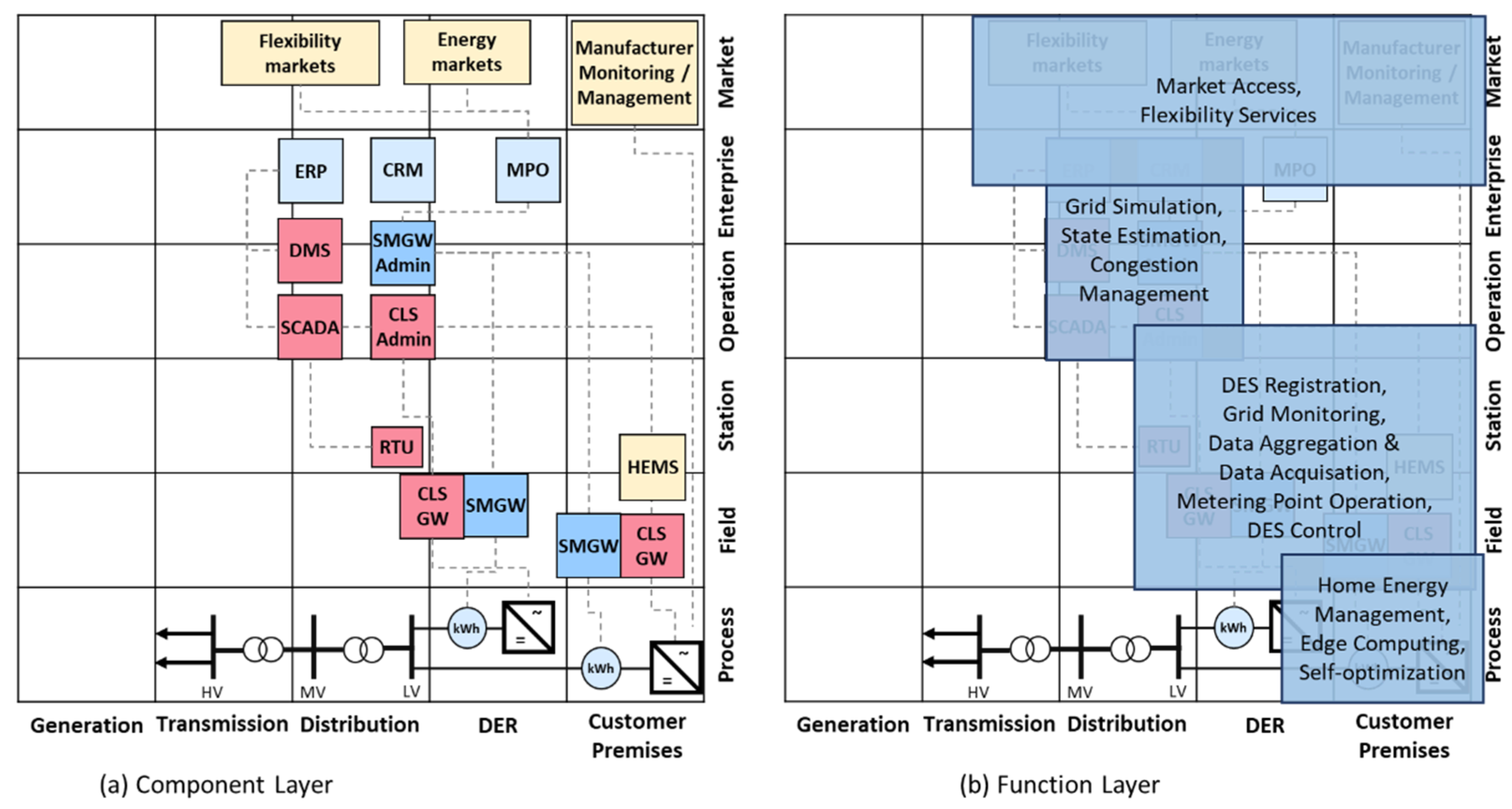
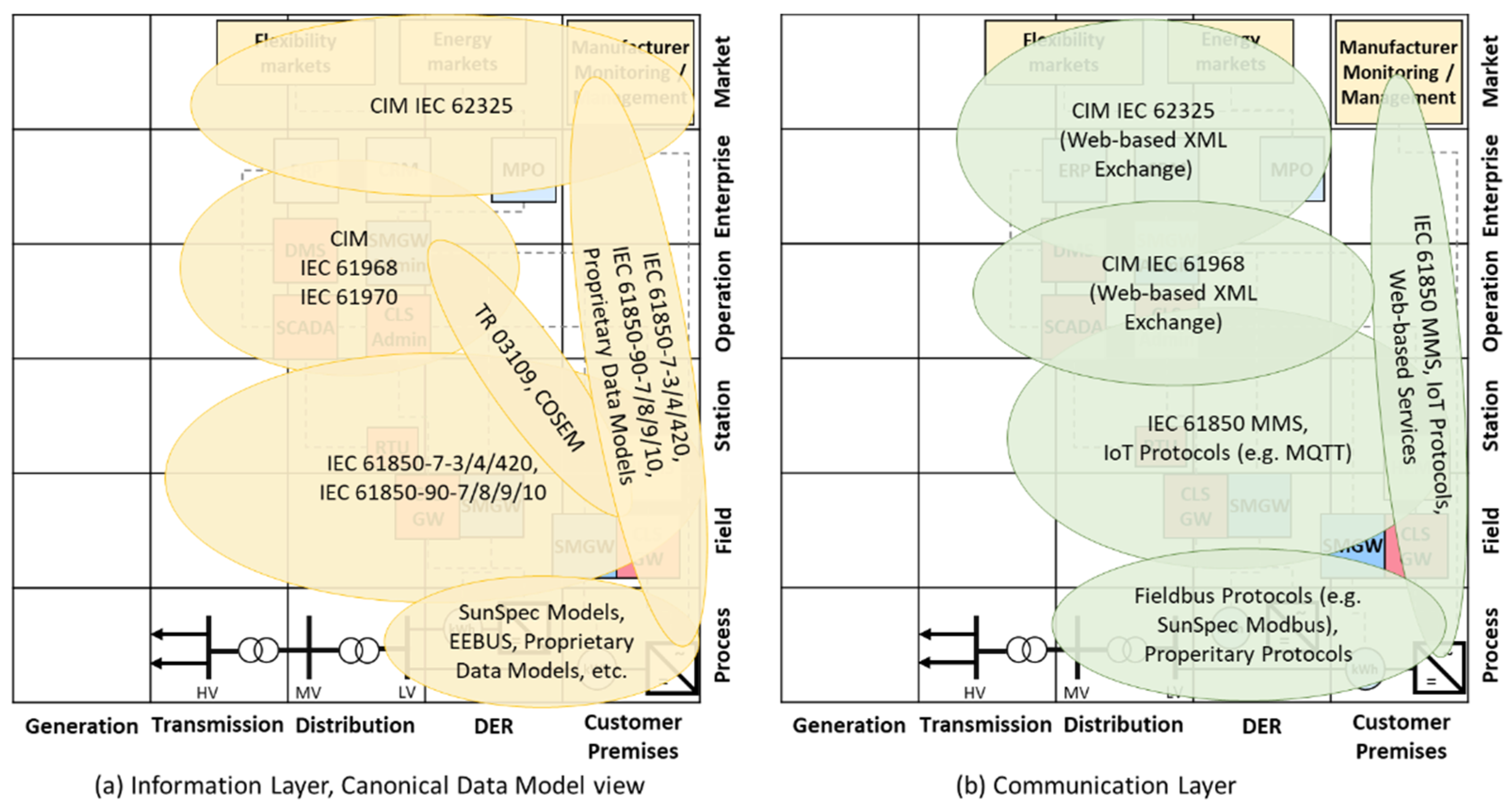
2.1. Smart Grid Modeling Concept and DES Data Model

The first step of integrating DES in smart grid systems is to gain a better understanding of the power grid modeling concept for smart grids. There are plenty of studies handling this issue; the authors of [21], for example, addressed new challenges for the modeling; in [22], the smart data architecture was outlined based on several research projects; the contents of [23] give us an overview on essential subsystems of a smart grid system, including the energy system, information system, communication system, management system and protection system. These publications also addressed the importance of data modeling and data integration in smart grids, which commonly defines the data structure and data interfaces of smart grid components corresponding to the power system architecture. Therefore—given by the requirements of grid communication and control—the data model is also a fundamental instrument for the implementation of telecommunication to DES and curtailment capability in the role of a DSO. Following this basic knowledge, the authors of [24] proposed a common platform for seamless microgrids operation with the usage of some common data models and communication standards.
Data models, telecommunication protocols and data interfaces have become vital for grid design and operation during the last few decades. Now the application of these Information Technologies and Operation Technologies (IT/OT) must reach out much deeper into the distribution grids to enable bidirectional data transmission, which enormously supports grid simulation and operation with high penetration of DES. Worldwide, there are diverse data models and protocols available for this purpose. As this paper mainly deals with the DES integration in DSO data systems, this SoA analysis accordingly concentrates on data models and relevant telecommunication protocols for distribution grids and DES. Several studies were carried out to categorize and introduce various commonly used grid communication protocols. Short descriptions of these protocols can be found in [25,26]. Some IoT (Internet of Things) communication protocols are introduced in [27]. As cybersecurity topics are increasingly taking on significance, a considerable number of studies have been carried out recently: The authors of [28] give a review of DER communication protocol features subject to IT-security concerns; Ref. [29] addresses vulnerabilities and cyberattack vectors of different protocols used for SCADA systems. An overview of the characteristics of standards or protocols for data exchange regarding the DES integration into the energy system is presented in Table 1.

2.2. Concepts for DES Data Model Integration in DSO Data Systems

To find an appropriate solution for the DES integration in DSO data systems, it is necessary to define the essential information objects to be considered, which vary from system to system. This is an elementary step for the selection of a proper data model and necessary communication interfaces, which plays a major role in the systematic design and the technical implementation of the ADMID. Depending on the scale of data systems and the potential application scenarios, an information object could be the topology of a distribution grid, the properties of grid components, substation functionality, GUI for grid operators, communication infrastructure, DES characteristics, measuring instruments or control units. One technical report [22] of the International Energy Agency (IEA) provides us with an overview of control strategies and communications technologies for the integration of distributed PV systems, while several recommendations for data models for the PV systems registration are given in another IEA technical report [43].
Specifically for the interest of DSOs, the optimal case in terms of grid operation is to have one comprehensive model that describes the grid topology, properties of grid components, DES characteristics and DES control parameters for the grid operator. An alternative solution would be a multi-agent architecture utilizing different data models or protocols and implementing model adapters to enable model conversion and data transmission among different applications. The worst case happens when various protocols and data models are used by different departments within one DSO, but they cannot effectively exchange information.
Considering the characterization of DES properties, the scope of parameters in one data model highly depends on its application scenario. Table 2 explains commonly used DES parameters by specifying their categories, information types and application purposes.
As the issue of data integration of DES has gained more attention recently, various studies have proposed different approaches to strengthen the data integration and the telecontrol of DES for future distribution grid operation:
CIM: In the research project “ESOSEG” [9], a CIM-based model-driven framework was developed and demonstrated to enable standardized data exchange between various data systems for different services within a DSO company [44]. A similar CIM-based system architecture was used in [45] to develop a distribution system application platform based on CIM model conversion. A US American utility company has recently published a study on the DER integration in DSO business processes using CIM [46], in which the business processes for DER integration are illustrated in detail; for instance, an enterprise-adapted CIM data model concept, as well as an integration framework, has been implemented. Major issues in [46] are that almost half of the used CIM entities are customized CIM-extensions and the communication to DES is not handled as a vital component.
IEC 61850: In Germany, the utilization of the IEC 61850 data model has been recommended for the implementation of the Controllable Local System (CLS) by “Network Technology/Network Operation Forum at VDE” (VDE FNN) [47], which is the technical regulator for power grids. Following this recommendation, the application of IEC 61850 data models for the DES integration including the bidirectional communication to SCADA and the encryption via Smart Meter Infrastructure (SMI) has been demonstrated in several German research projects. Technical details on this work are summarized in [10,48]. Another example of implementing the IEC 61850 data model for the control of energy devices in microgrid applications is presented in [49].
IEEE 2030.5/SEP2, IEEE 1815/DNP3 and SunSpec Modbus: In the USA, these standards are constantly being adjusted for the integration of DES. The IEEE 2030.5 Smart Energy Profile 2 (SEP2.0) has been extended using IEC 61850-7-420 logical node classes for DER components to meet DER integration requirements for CA Rule 21 [50]. The SunSpec Alliance has designed the SunSpec Public Key Infrastructure (PKI) and extended the SunSpec Modbus specification with the 700 series along with the DER information model to enhance the DER access for stakeholders including DSOs. To include standardized interoperability functionality, the IEEE 1547 standard was updated in 2018 with a specification for technical requirements relevant to the performance, operation, testing, safety considerations and maintenance of the interconnection of DES in electrical grids [51]. In terms of physical interconnection requirements and test procedures for DER, the work in [52] delivers an overview on the evaluation of DER interoperability to IEEE 1547.1 for SunSpec Modbus DER, IEEE 1815 and IEEE 2030.5.
Industrial communication protocols: As commonly used industrial communication protocols, Modbus TCP, respectively, Modbus RTU and OPC UA, provide diverse possibilities for the data acquisition and control of distributed devices in the smart grid scope. For example, the authors of [53] have analyzed several industrial communication protocols and proposed a multi-layered architecture based on Modbus TCP, which has been applied to the monitoring and automation of a PV-based smart microgrid. Nevertheless, the open development nature of Modbus TCP imposes the restriction that it does not apply to standardized model-driven approaches in terms of DES integration. In [54], the utilization of OPC UA in the smart grid domain was expounded with the focus on academic research efforts; one advantage of OPC UA is the object-oriented specification, which allows the definition of information models. OPC UA, though, does not provide a standardized comprehensive model specification, which reduces the interoperability of involved systems; the authors of [54] also pointed out that recent researches related to OPC indicate a trend towards mapping existing data models to OPC UA.
Industrial IoT protocols: Most industrial IoT protocols are designed and deployed with a wide spectrum of potential use cases; therefore, they do not directly harmonize with data systems on the utility side. Various studies such as [27,55] have investigated the deployment of IoT protocols in the smart grid context. IoT protocols have advantages regarding communication performance and real-time interaction; e.g., MQTT and Kafka are prominent representatives of the publish–subscribe architecture of telecommunication, which leads to a radical shift from the classical master–slave hierarchy to a loose coupling architecture of a message broker with equal access privileges for different services. However, there is a lack of implementation for DSOs on the application level regarding technical and informative constraints defined by other smart grid communication standards. In terms of DES integration into DSO SCADA, a specific implementation of model mapping services according to the infrastructure and requirements on the utility side is usually necessary. Hence, from a standardization perspective, these IoT protocols may be feasible solutions to overcome obstacles related to DES communication performance, but DSOs cannot benefit from them tremendously in the data model integration process.
From other points of view, various important aspects for the DES integration in SCADA have been addressed in several studies. The authors of [56] predicted future trends of SCADA system architecture in the smart grid due to the integration of ICT. In [57], SMI-based IT/OT integration solutions were proposed for different smart grid applications. A web-based visual analytics interface was designed in [58] to integrate data from diverse data sources, such as SMI, Geographic Information System (GIS) and SCADA. The work in [59] provided a cross-infrastructure test framework coupling SCADA and Power-Hardware-in-the-Loop environment to validate the interoperability of information models in smart grids. In [60], a distributed multi-versioned model data management architecture for SCADA was suggested aiming at data model version control using NoSQL (Not Only SQL) data storage.

2.3. Individual Automation Approaches for Data Integration

The utilization of a standardized data model provides a solid basis for the DES integration in DSO data systems; furthermore, advanced automation mechanisms are necessary to ensure an efficient process aimed at integrating an enormous amount of DES in future distribution power grids. For some of the standards mentioned above, several approaches or tools have been developed for certain use cases with relatively low automation grades and interoperability. Available commercial solutions for DES data integration, which are mainly driven by the individual customer demand and using proprietary products, are faced with the same challenge.
Regarding the utilization of CIM, ENTSO-E has developed CIM profiling tools to simplify the manual CIM modeling process by utilities, mainly TSOs [61]. Regarding the CIM models for the distribution power grid, one possible automation mechanism was demonstrated in [9], where the CIM models were used as a centralized information exchange platform and different CIM adapters were implemented to enable the bidirectional information conversion. However, this CIM platform did not involve the DES characteristics; for further development and optimization, an efficient automation approach is required. Other researchers introduced in [62] a CIM-compatible Python library, which helps to parse, import and export CIM models between data systems for smart grid applications. Though, this toolkit does not cover the DES properties.
The IEC 61850 standard series provide a wide range of substation automation and protection functionalities as well as a large scale of extensions for DES modeling. Yet apparently, automated IEC 61850 data model exchange or conversion has not been developed with high compatibility with different DSO processes. Another constraint by the utilization of IEC 61850 is the representation of the grid topology, as the IEC 61850 standard series reflects the communication architecture of substations or subordinate distributed systems. Hence, CIM would have higher priority over IEC 61850 by utilities due to its compliance with the DSO–TSO coordination process; the actual issue is the harmonization of CIM and IEC 61850. Related studies like [63,64] can be traced back to 2009, where ontology approaches or object mappings for substation models were implemented and tested. Further development has successfully improved the automatic mapping for signal processing [65] and established the links between the parameters in IEC 61850 and CIM models [66]. The work in [67] also indicates the trend of the harmonization of CIM and IEC 61850, in which the unified modeling is preferred and the usage of a unified model or meta-model has been suggested. However, most of the approaches mentioned in [67] were restricted to substation applications and have not been extended with DES applications in distribution grids.
Additionally, the business-oriented concern of SCADA manufacturers is another important aspect of the recent implementation of ADMID. Based on experience, the product development of SCADA systems is normally market-driven and customer-oriented. Currently, their customers are generally working with systems at HV and MV levels, and there is less demand on the LV side since the traditional power system design and operation follow a top–down approach, as explained in the introduction. Thus, SCADA manufacturers primarily focus on IT security, implementation of interfaces and supporting modules for the modeling of MV and HV grids in SCADA, as well as the evaluation of existing infrastructure. Although new topics like distribution grid modeling, DES integration and ADMID have already drawn attention on the manufacturer side, they are by now not a standard functionality required by the DSOs, which leads to a lack of innovative effort in this respect.

2.4. Technology Gap Analysis

Overall, the studies mentioned in this section provide important insights into the application of various standard data models in energy systems including the telecommunication features. Corresponding to the components and functions mentioned in Section 1, the deployment of data models and communication protocols for the DES integration and distribution grid operation is suggested in Figure 2.
However, the SoA analysis also reflects a technology gap for ADMID implementation in the academic domain and the industry. Despite the continuous efforts of standardization committees, the increasing DES in distribution grids has not raised an alarm on the utility side, which leads to a lack of innovation motivation. Considerable studies are devoted to the automation of smart grid systems using different protocols, or the harmonization of various data models to fulfill the demands of all processes in the planning and operation of distributed energy systems. However, no study has suggested the utilization of standard, comprehensive DES data models to reach a wide coverage of DES properties as well as the assurance of operational interoperability and economic benefits.
To fill the huge technology gap caused by the digitalization of energy transition and systematically support the mass DES data integration in future distribution grids, this paper provides a proof-of-concept study on one ADMID approach for DSO SCADA based on the utilization of standardized, comprehensive IEC 61850 data model and information processing logics. The whole ADMID framework still requires more efforts for further implementation and interoperability tests to reach a higher Technology Readiness Level (TRL).

3. Essential Components and Use Cases

Before proceeding to a detailed description of the proposed methodology and technical implementation, it is necessary to have an overview of used hardware and software components as well as potential Use Cases of the proposed ADMID.

3.1. IEC 61850 Compliant Data Model

As discussed in the preceding section, one of the widely used communication protocols in MV and LV power grids is the IEC 61850 standard series because of its extensive data model, comprehensive functionality, universal usability, high interoperability and definitions for communication architecture. In the IEC 61850 context, there are two completely different communication strategies, for which a similar data model structure specification is used:
  • Generic Object Oriented Substation Events (GOOSE) [33] and Sampled Value (SV) [34] for substation automation, in which the publisher–subscriber concept is used to multicast or broadcast GOOSE/SV messages in a substation network without the utilization of a central system.
  • Manufacturing Message Specification (MMS) is specified by the international standard ISO-9506; the document IEC 61850-8-1 further defines the application of MMS as the standard service-mapping in a server–client form for TCP/IP-based telecommunication [33].
Compared to GOOSE/SV, MMS provides users with the possibility of IP-oriented routing at Layer 3 in the Open Systems Interconnection (OSI) model for decentralized systems, and the configuration flexibility of reports ensures the data transmission for different conditions. These features make IEC 61850 MMS more eligible for the implementation of DES integration approaches in practice. Based on the SoA analysis and the objectives of this work, the IEC 61850 MMS protocol and associated data model definitions were selected as the first elementary component for the implementation of the proposed ADMID. Various reasons can stand for this choice:
  • Standard documents IEC 61850-7-3 [31] and IEC 61850-7-4 [32] have clearly defined the Common Data Classes (CDC) and compatible logical node classes, which facilitates systematic data modeling for DES and improves the interoperability and reusability of the DES data models in the SGAM information layer.
  • Specifically in terms of MMS, a basic communication profile is defined by IEC 61850-8-1 [33], essential communication configurations such as Report Control Block (RCB) and diverse control parameters are directly contained in the data model. Because of these, a bidirectional communication to distributed intelligent devices is possible in the SGAM communication layer, which further provides DSOs with the flexibility to implement proper remote-control algorithms for DES or on-site control with interaction to a local energy management system.
  • The IEC 61850-compliant data model is normally self-described and will have a hierarchic structure. One supplementary standard document, IEC 61850-7-420 [35], provides enhanced DES compatibility with commonly used device types and numerous DES properties regarding the information categories listed in Table 2. Therefore, the conversion of DES characteristics to IEC 61850 parameters as well as the integration in the existing grid model (e.g., CIM) on the DSO side is relatively straightforward on the application level.
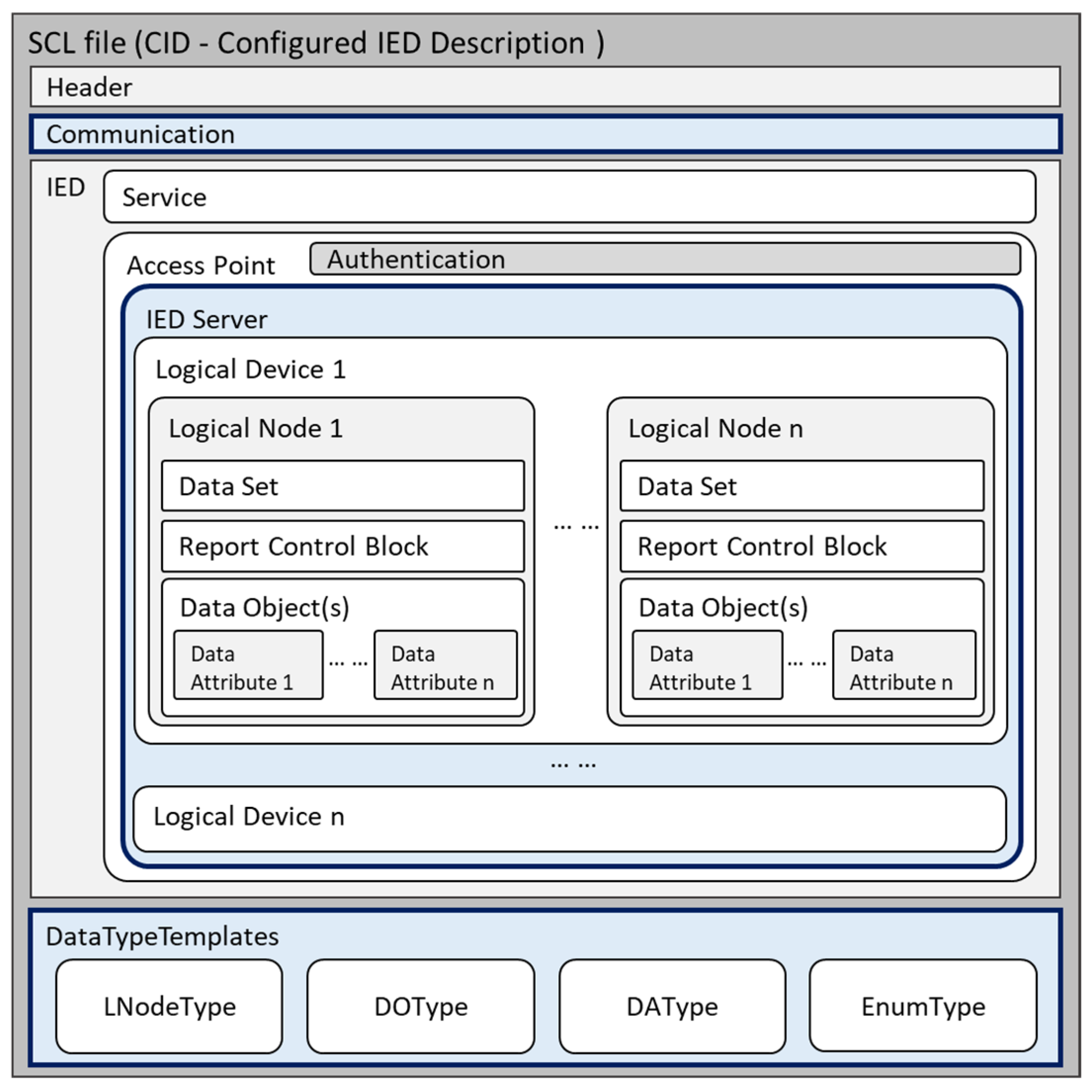
  • With the hierarchic structure, IEC 61850 data models usually have a file-based representation, which is modeled as an Extensible Markup Language (XML) file coded with IEC 61850 specific Substation Configuration Language (SCL). Consequently, the file parsing process is uncomplicated, and the modeling of internal links between grid element parameters and communication unit parameters or graphical objects can be implementable by modification of the XML file.
  • As derived from the SoA analysis, the IEC 61850 data model has a high potential for harmonization with CIM, which is—as mentioned in Section 2.3—widely used by the grid operators. Despite the informative gaps between these two standards, the utilization of the IEC 61850 data model facilitates the general system integration into the existing infrastructure by grid operators.
An example of the IEC 61850-compliant data model is presented in Figure 3. Even when one certain DES property is not yet included in the current IEC 61850 data model definition, it can be added to the data model as a customized parameter.

3.2. DSO SCADA System

The Experimental Distribution Control Center (EDCC) at THU is the second important software and hardware component. The core functionality is based on a SCADA system with the type of Spectrum Power 5 by Siemens AG [68]. Although the EDCC is named an experimental system, it is equipped with the same sub-systems and functionalities as the industrial product used worldwide by many grid operators. More specifically, it consists of information management, database, real-time environment, communication interfaces and IT-security relevant components. The data storage in Spectrum Power 5 is based on an embedded Oracle database, and WinCC is integrated as a visualization tool and machine–machine interface. Besides, an integrated OPC UA interface can be used for the data transmission between Spectrum Power 5 and the simulation environment or external databases such as InfluxDB [69]. In the remaining parts of this paper, the term EDCC will be used instead of the general term SCADA when the technical implementation or test procedure refers to this grid control system at THU.
In an IEEE recommendation [36], the Substations Committee of the IEEE Power and Energy Society has pointed out that implementing IEC 61850 back to the SCADA master has been uncommon and mapping to another protocol is required, which is an aspect from a substation-automation view. Regarding the MMS communication to DES, it is possible to establish a TCP/IP connection between the SCADA and DES. Such IEC 61850 communication functionality has been implemented by the manufacturer and is provided in the EDCC software. According to the IEC 61850 definition, an IEC 61850-compatible field device that also has communication interfaces is denoted as Intelligent Electronic Devices (IED). Hence, two participants of an IEC 61850 telecommunication connection have the roles of IED server and IED client, respectively. In this case, the EDCC works as an IED client and requests the TCP/IP connection actively to the IED server for the transmission of MMS reports or control commands. This IEC 61850 compliance of the EDCC allows test and validation of implemented automation approaches on the function level, in which the IEC 61850 telecommunication is observed and analyzed.
As mentioned in Section 2.2, the integration of IEC 61850 data models usually requires conversion into another format compatible with DSO data systems. The EDCC internally uses a CIM interface for Resource Description Format (RDF/XML), which follows the outdated CIM schema version 12 and contains several extensions defined by the manufacturer. Alternatively, the EDCC has an XML-based interface eXchange Data Format (XDF/XML) for file import/export, which has no dependency on the CIM schema.

3.3. Overview of Used System Components

Based on the IEC 61850-compliant DES data model and fundamental functionalities of EDCC, a set of essential system components were used for the implementation and test, as shown in Table 3.

3.4. Use Cases of the Implementation

To ensure the usability of the proposed ADMID, two different scenarios were implemented and tested in the scope of this paper. This section describes the planned Use Cases of the proposed approach; a more specific, detailed explanation of the technical implementation and test procedures will follow in Section 4 and Section 5.

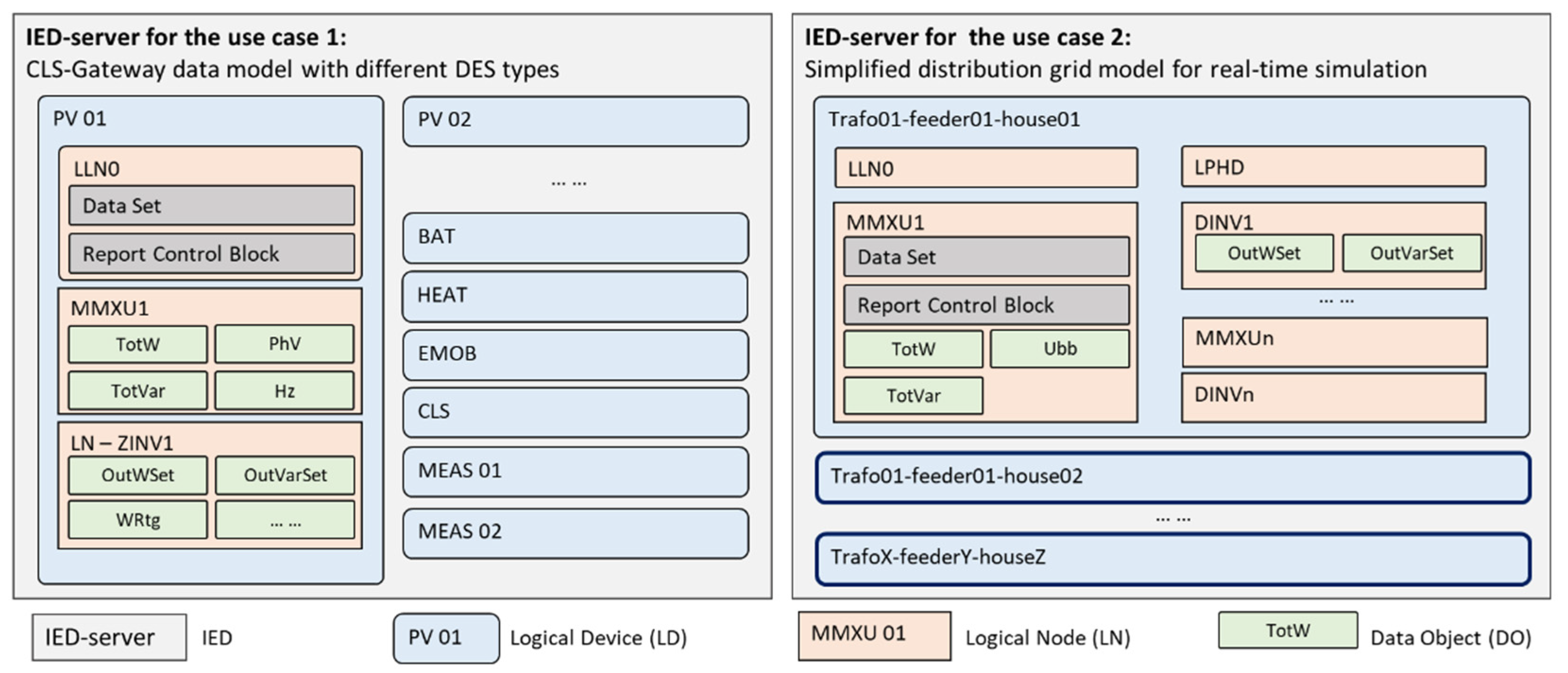
3.4.1. Use Case 1: Integration of the IEC 61850 Data Model Containing DES Characteristics

The first Use Case focuses on the modeling of DES characteristics and the realization of telecommunication to DES. IEC 61850-compliant data models for CLS gateways should contain a sophisticated data structure that builds a DES digital twin representing device properties, measurements and control settings. In this paper, the IEC 61850 data model has been deployed as a part of the CLS gateway’s software, which enables intelligent, bidirectional communication to various types of DES via standard or proprietary protocols for measurement acquisition and remote control [48]. The architecture of the secured communication infrastructure is presented in Figure 4, which was also utilized in the field demonstration of the research project “C/Sells” [77]. Each CLS gateway describes one or more DES interconnected with the grid. Considering that each DES type might have unique properties and data types, the script package is required to have enhanced compliance for IEC 61850 data classes and broader coverage of information types, such as enumerated device status, digital measurements, control settings and schedules.

3.4.2. Use Case 2: Integration of an IEC 61850-Based Virtual LV Grid Cell Coupled with a Real-Time Simulation Environment

The second Use Case studies the integration of the IEC 61850 grid model containing the schematic topology of a real test area in the distribution grid, which is coupled with a real-time grid simulation environment. More technical details on the structure of the IEC 61850 grid model and the used real-time simulation environment are documented in [71,74]. Regarding the concept of a digital twin for distribution power grid and real-time data interface, a similar approach has been demonstrated by another institute in Germany as described in [78].
Compared to Use Case 1, the basic concept of the automation approach remains the same, whilst the data nodes in this model have a high duplicating character, as the measuring devices for each household or PV system may have a relatively similar data structure containing several analog measurements. Therefore, the Point of Common Coupling (PCC) of each household could be modeled as units with repeating nomenclature, which in the meantime facilitates the automated generation of GUI for grid operators. The simulation environment is presented in Figure 5, in which the script package has the task to automatically integrate this grid model including graphical elements in EDCC as a sub-geographical region supplied by one transformer station.

4. Automation Methodology

4.1. Data Model Integration Process in DSO SCADA

Having discussed the essential components and Use Cases, this section now moves on to the methodology used for the implementation of ADMID. In terms of distribution grid modeling with high penetration of DES in SCADA and data integration requirements for smart grid applications, several key factors must be considered, and some important terms should be defined for a common understanding:
  • TOPO model: For real-time grid operation, the EDCC database requires a grid model, in which the hierarchic structure that corresponds to the physical and topological construction of a distribution power grid is clearly defined, and necessary parameters on each hierarchy level are configured. This paper uses the term TOPO to refer to this topological grid model. Besides the grid topology and parameter definitions, a TOPO model should also contain comprehensible descriptions of the grid parameters for the grid planners and grid operators.
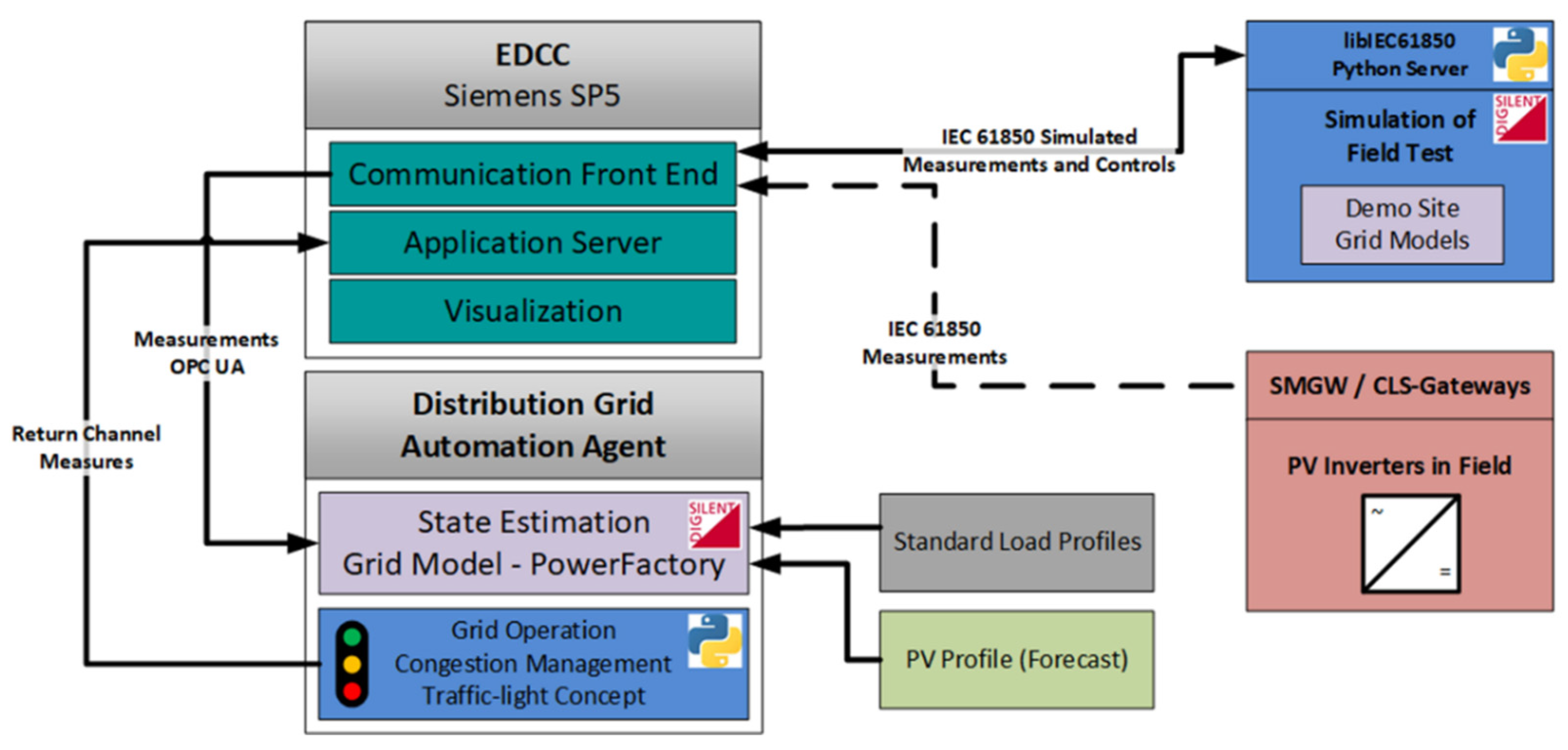
  • CFE model: In EDCC, the communication interface is deployed as a Communication Front End (CFE) module; the term CFE also refers to the data model representing the telecommunication to IEDs. As communication has become a central issue for the DES integration, which is one important advantage of utilizing the IEC 61850 data model, the grid measurements or DES parameters contained in an IED server data model also should be available in the EDCC database as CFE endpoints.
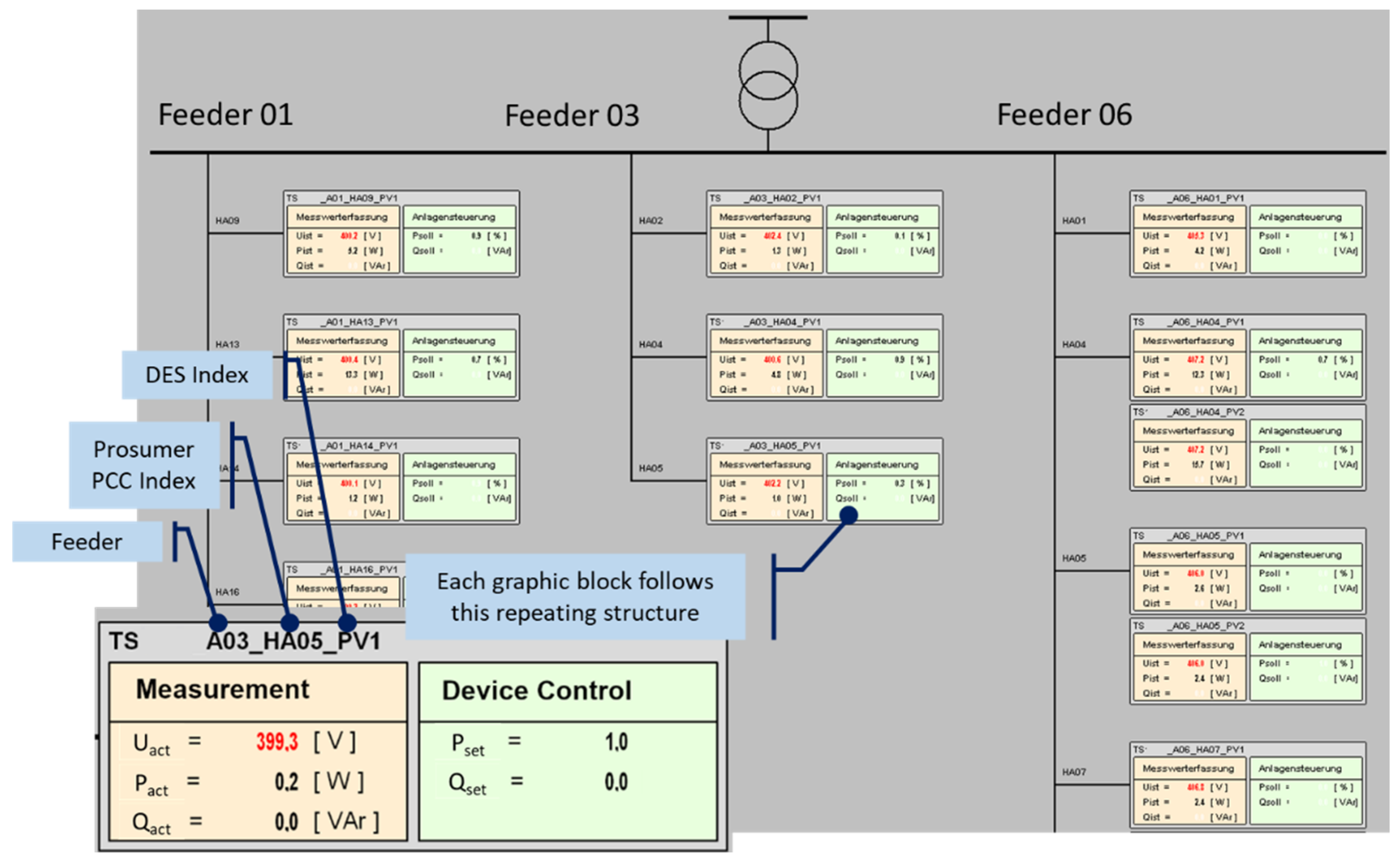
  • VISU model: A GUI should be available for the grid operators to visualize measurements and execute control commands, which can be described with the term VISU.
  • LINK element: Another essential part of ADMID is the clear reference of parameter dependencies to elements in other sections or systems. In EDCC, this dependency is implemented by identifying each object’s Globally Unique Identifier (GUID) or RDF-ID, which is denoted with the abbreviation LINK.
The process for DES integration in DSO SCADA in a conventional way would consist of the following steps:
  • Manually create a TOPO model that represents the topology of the distribution grid.
  • Create a data model for communication units. The form of the data model may highly depend on the manufacturer of the telecommunication equipment.
  • Convert the data model of telecommunication devices in readable format for SCADA and import it into the SCADA database as a CFE model.
  • Manually modify the TOPO and CFE models by adding LINKs of TOPO elements to each CFE parameter.
  • Manually create or modify the VISU model and add LINKs of TOPO elements to the VISU graphic objects.
For an IED with only 20 parameters, the whole integration process may take up to two hours depending on the complexity and similarity of the parameters. This simple example underlined the necessity of a data model-oriented ADMID to handle the data integration of large numbers of DES in DSO SCADA.
The proposed ADMID has been adapted to the characteristics of future smart grids with a high share of DES and the cellular grid structure projected in Germany [8]. More specifically, the future distribution power grid will have an increasingly high number of DES with high similarities in the data structure. The cellular structure of a power distribution system would allow using reproducible blocks of elements on different cell levels, from the lowest level in customer premises, through the PCCs and feeders to the MV/LV transformer-station level. The concrete modeling concept could then be adapted according to utility demands.
Based on the features and advantages of IEC 61850 data models discussed in Section 3.1, it can be seen that most of the key factors mentioned above can be well handled by the utilization of these standard data model blocks. The main challenges for the proposed ADMID are the identification and allocation of DES information in the initial IEC 61850 data model, the automated creation of TOPO, CFE and VISU models according to available information, the automated establishment of crossing-model LINK elements and the provision of output information for the EDCC in a standardized form.
Concerning the selection of the EDCC file interface, the XDF/XML format was chosen to ensure the integration of all required IEC 61850 parameters. To achieve high conformality with existing grid models by DSOs, the output format should be adapted to CIM RDF/XML in further work.

4.2. Automation Methodology for EDCC

The core of the implemented automation methodology is to add more information to the distribution grid topology and DES characteristics to the IEC 61850-compliant data model, parse the hierarchical data model and build TOPO, CFE and VISU models including LINK elements. In this way, the conventional TOPO-based manual DES integration process can be transformed into a DES model-oriented automation integration process. The described automation methodology was realized with a Python script package named “edccADMID”, as it aimed at assisting DSOs by the integration of DES in their SCADA system and was implemented primarily for the EDCC at THU.
The edccADMID package mainly has two core tasks: parsing the information contained in the source IEC 61850 data model as well as mapping the parameters to the XDF models and exporting the XDF/XML files. The parsing logic is given by the structure and data classes in IEC 61850, while the mapping logic is based on data structure and parameter types defined for XDF/XML import in EDCC. Additionally, a visualization logic was implemented for the automated generation of GUIs. The entire workflow of ADMID in EDCC is represented in Figure 6. All the steps are automatically performed by the edccADMID based on the source IEC 61850 data model, except for the last import action in EDCC.
After the import job is completed in EDCC, the CFE module will actively request an IEC 61850 server–client MMS connection to the configured IED server. When the data model has been correctly integrated into EDCC, the configured data transmission should automatically start. The IEC 61850 communication between EDCC and the IED server has been used for the test and validation of the proposed ADMID approach.

4.3. Used IEC 61850 Data Classes and Implementation of Parsing Logic

Previous sections have pointed out the role of the compliant IEC 61850 data model for the script implementation. Additionally, it is necessary to briefly expound the basic principles of IEC 61850 data modeling, including the usage of CDC and data model structure. The most important precondition for the implementation of the parsing logic is to comprehend the fundamental IEC 61850 data model structure. The general architecture of an SCL file in Configured IED Description (CID) format is illustrated in Figure 7.
According to IEC 61850-7-3, a CDC helps define the Data Objects (DO) within a Logical Node (LN); therefore, on the DO level, a CDC is composed of constructed Data Attribute (DA) classes. The properties in a specific CDC define the relation between their attributes and the Functional Constraint (FC) as well as the possible trigger options for RCB [31]. Specifically for the implementation of ADMID, the CDC and FC have a higher priority corresponding to the requirements of the mapping logic.
As this standard series has been under continuous development for more than 20 years and a wide range of DER extensions are available by now, most of the commonly used CDCs can be covered in the IEC 61850 standard documents. The Use Cases in this paper are subject to proof-of-concept research; therefore, simplified data models are used to describe the distribution grid topology, communication interfaces and DES properties. The used CDCs and FCs are shown in Table 4 and Table 5, respectively. A fixed definition of CDCs would help the parsing logic to restrict the DO in the Python dictionary object, while the FC types are used by mapping logic to configure parameter types in the XDF/XML model.
The data models for Use Cases in this paper are provided by different services and are structured for different purposes; thus, the architecture of them has significant differences as shown in Figure 8. Because the SCL data model utilized for Use Case 2 usually contains more hierarchies than what the IEC 61850 data structure can handle, regarding the implementation and demonstration of ADMID, a part of its structure or dependencies needs to be stored directly in LD or LN name using specific separator characters. Subsequently, the data model should accordingly be strict concerning this predefined name convention to avoid errors during the data model conversion process.
After the SCL data model is read in Python, the information contained in the SCL file will be extracted and reconstructed in a Python dictionary. Although this dictionary is strictly systemized, the structure is still too complicated to be further processed. For this reason, the parsing logic of edccADMID is committed to examining all information objects, filtering unnecessary information and reordering the information in a form, in which the hierarchical structure can be retained. Then, all information can be properly processed in an uncomplicated way by the mapping logic. This preprocessed information is a series of restructured dictionaries and list variables in Python.

4.4. Implementation of Mapping Logic

Subsequently to the preprocessing work performed by the parsing logic, the output variables are handed over to the mapping logic for further data model conversion. In this phase, the mapping logic was implemented according to the technical requirements of the target system EDCC.
As an essential part of ADMID, the role of mapping logic can be described using a similar approach of general data integration. In this case, the integration system I is described as a triple following the data integration pattern specified in [79]:
I = G ,   S ,   M
which is constituted by:
  • G describing the global schema defined by the XDF/XML structure in EDCC, where all the information structure is given in detail.
  • S representing the source IEC 61850 SCL discussed in the previous section containing CDC and FC as modeling constraints C.
  • and a set M of the applied mapping logic determining the information transformation from S to G.
It must be considered that the data integration process handled in this paper is not query-language-oriented; therefore, it requires constraint-based variable management V in Python and additional local resources L(G) derived from an external configuration file. Consequently, the associated mapping logics are supposed to be denoted as operations OG over G rather than queries. Following the expressions used for constraint-based XML-mapping introduced in [80], the mapping language can be described as:
M = for   each _   a 1   in _   s 1 ,   ,   a n   in _   s n exists _   p 1   in _   g 1 ,   ,   p m   in _   g m where _   V ,   L ( G ) with _   p 1 = c 1   and _   and _   p k = c k
where the logical operators are underlined, a i in s i represents DAs in the source IEC 61850 variables provided by the parsing logic; g i specifies the RDF/XML information object definitions given by EDCC; p i implies the parameters configuration of a certain DA; c i refers to the CDC and FC constraints given by the IEC 61850 definition; and V and L(G) in the where condition indicate the rules for the information transformation between S and G. Accordingly, the output operations OG in the Python environment can be described with the following expression:
O G = for _   a 1   in _   s 1 ,   , a n   in _   s n where _   M returns _   r
where r is the mapping output variable in Python following the XDF/XML schema of the target system EDCC.
More specifically, the conversion of an IEC 61850 DA into the XDF/XML model is determined by the combination of the parent DO’s CDC and its own FC. Then, the mapping logic must select mandatory DAs oriented towards the processibility of the IEC 61850 CFE interface in EDCC, because the IEC 61850 MMS data transmission is based on the configuration of RCB, and several specific data types like strings are not supported. During the mapping process, a random GUID will be generated for each parameter or object in the XDF/XML model. For instance, the mapping logic is also in charge of the establishment of LINKs between TOPO and CFE objects based on the object identifiers and assigned GUIDs.
Considering that the target XDF/XML model is not a standardized format and no technical specification was available, it was necessary to use reverse engineering to some extent. In this context, the required data fields for an XDF/XML were reversely structured and categorized. The properties and data attributes of commonly used XDF/XML elements were coded in templates, while a summary of different parameter types for each category was stored in a configuration file, which was to be loaded during the initialization of the mapping logic.

4.5. Implementation of Visualization Logic

For a data model with highly repeating contents, it is possible to use a generic element block to create a GUI in EDCC for data visualization and remote control. While for the IEC 61850 data model consisting of more LD or LN with a unique structure, the required mapping logic for graphic elements is accordingly much more complicated. Consequently, the visualization logic for the generation of the VISU model was implemented only for the IEC 61850 data model utilized for Use Case 2 or other data models with similar construction.
Before implementing the logic, a graphical block template for each consumer or prosumer should be defined. The replication of the templates is based on grid topology. Each required value, label, symbol and line is modeled as one graphical element in the VISU model, measurements and telecontrol parameters are linked to the IEC 61850 DA in the TOPO model by GUID-based LINK elements. The visualization logic is responsible for the generation of graphical blocks with an appropriate position in GUI and the creation of LINK elements between data points in TOPO and VISU models. The graphical view of a prosumer template is presented in Figure 9, in which the object sizes and distances were predefined as variables in visualization logic. After processing by visualization logic, a VISU XDF/XML was generated for each transformer station with the graphical representation of grid-connected consumers and prosumers.
The entire structure and workflow of the edccADMID script package are illustrated in Figure 10 on the implementation level, including the inputs for each processing logic and the associated Python variables by each step.

5. Test and Validation of the Proposed ADMID

5.1. General Test Procedure

For testing the overall functionality of the proposed ADMID approach, a four-stage-test procedure is followed. Due to the high complexity and variety of involved components, there is the necessity to sequentially examine different steps along the integration process to ensure the proper functionality of measurement and setpoint transmission through the EDCC.
(1)
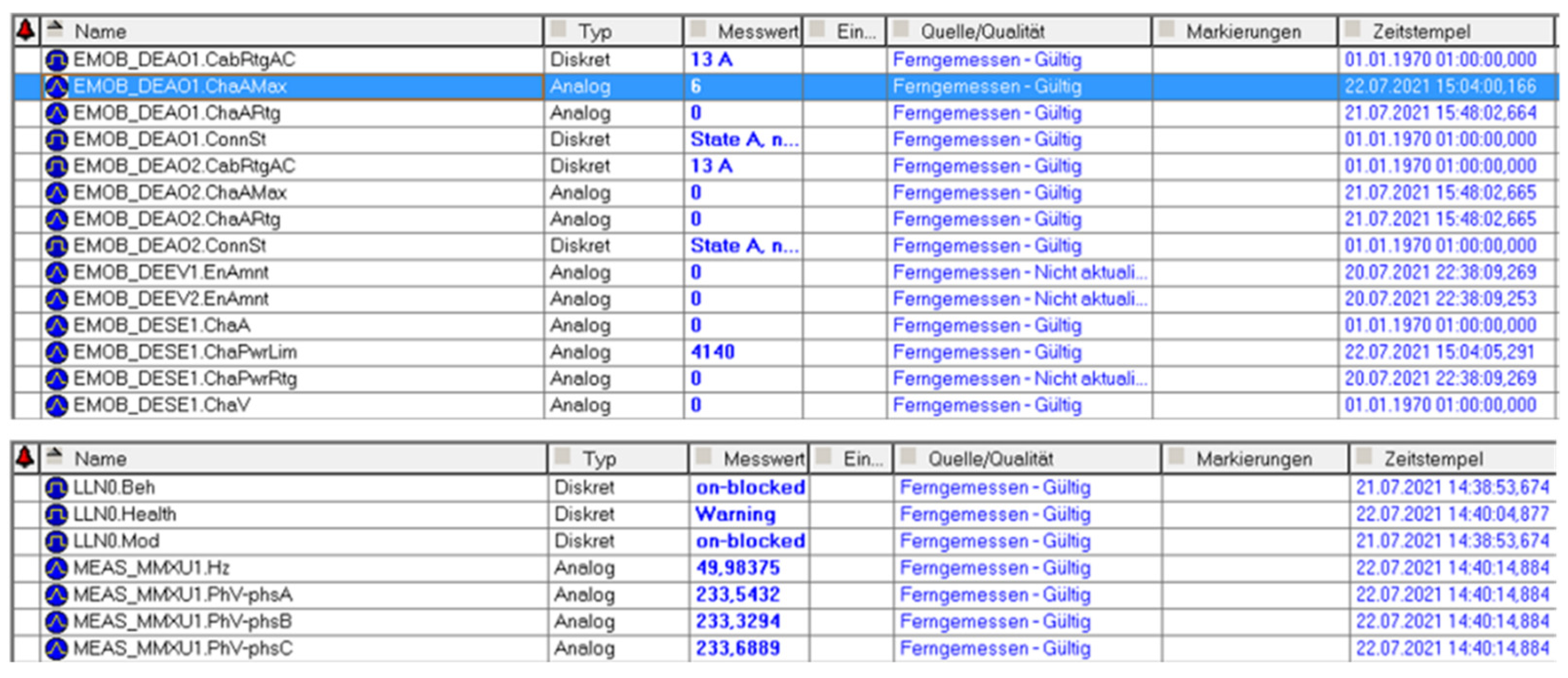
Validation of the IEC 61850 Data Model
Starting with any IEC 61850 data model from utilized electrical equipment, e.g., PV inverter, electric charging station, etc., a validation against IEC 61850 conformity must be conducted. Even more—since the IEC 61850 allows modeling a wide diversity of customized data objects—derivations from standardized requirements can occur and must be adjusted to comply with the IEC 61850 criteria. The IEC 61850 data model is defined through the SCL file, which reflects a typical hierarchical XML structure. All the defined nodes, objects and attributes in the data model follow this scheme. IEC 61850 validation tools examine this structure and validate the mandatory definitions. Suitable validation tools are provided by the EDCC itself as well as different other vendors, like the IEC 61850 modeling tool used for this implementation. Several vital contents are listed in Table 6.
(2)
Validation of the Data Model Integration into EDCC
For the second stage of the test procedure, the model can then be transferred to the integration process into the EDCC. In this step, the contents contained in the IEC 61850 SCL file will be validated by the logics of edccADMID during the model conversion process. Additionally, the generated XDF/XML files will be examined and validated by the EDCC during the XML import. The key validation criteria are defined in Table 7.
One integration test is passed when the required XDF/XML files are successfully generated and the job manager of EDCC does not raise any error message. In case warnings or errors are returned during the integration process, the system logs of EDCC and the logfile generated by the proposed ADMID can be used for debugging purposes.
(3)
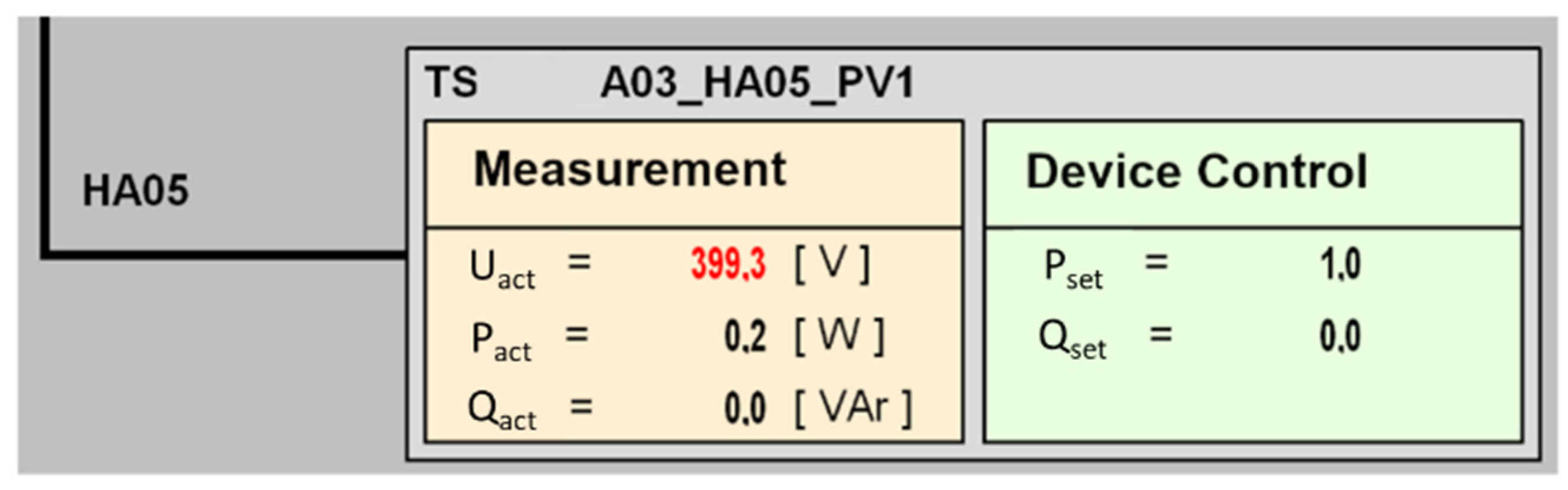
Validation of Correct Measurement and Setpoint Transmission
Once the data model is integrated into the SCADA environment and all connections between the relevant data points are established, the third step of the test procedure can be conducted. This step involves the validation of the correct transmission of measurement data and setpoints between the EDCC and the corresponding remote equipment. Therefore, the EDCC can be integrated into an automated multi-stage test bench where it serves as the System Under Test (SUT). An example of this procedure was implemented at THU for testing CLS gateways and can be taken from [81]. During this automated test procedure, the EDCC will be examined for the essential functionalities and validated against determined metrics and criteria. Essential functionalities begin with the proper establishment of the connection to the IEC 61850 server as well as the transmission of the data model to the IED client, in this case the EDCC. This test bench also realizes the possibility to characterize the functionalities, by means of measuring the duration of connection establishment or the duration of measurement, respectively set point transmission. Finally—based on a Software-In-the-Loop setup—this setup features high repetition rates and allows for detailed validation and evaluation of communication properties.
(4)
Long-Term Observation of the Data Transmission
Furthermore, the IEC 61850 MMS communication should be observed in real-time over a longer period to determine the integration status of the DES systems. To specifically evaluate the telecommunication functionality and relevant data interfaces, common packet capture tools like Wireshark or other IEC 61850 monitoring tools can be used for the recording of the IEC 61850 MMS traffic. For the analysis and visualization of the captured data, an IEC 61850 MMS data evaluation tool was implemented at the THU, which has been briefly introduced in the final report of one research project [82].
Stage 3 is primarily applicable for the prequalification test or the type test when changes in the data model or software occur. Under certain circumstances, Stage 3 can be skipped, the test procedure will then proceed directly to Stage 4 after the remote connection to the DES is established. This article mainly focuses on the validation of Stage 4 and presents the validation results based on the robust telecommunication to the IED servers in the simulation environment or on field test sites.

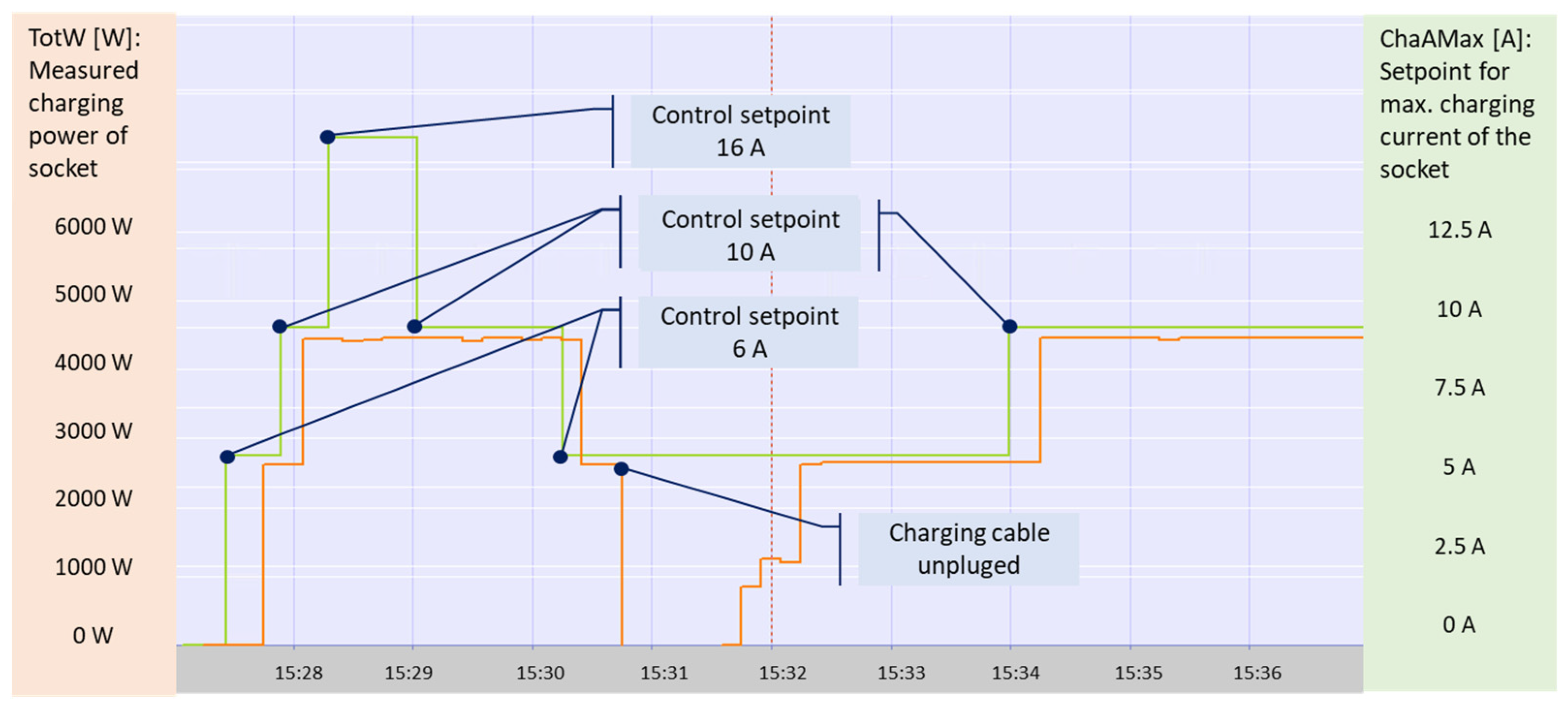
5.2. Test and Validation for Use Case 1: IEC 61850 Compliant CLS Gateway

The CLS gateway deployed at THU contains specific software that ensures compliance with different types of DES. The validation process of a CLS gateway with SunSpec conformality using the previously mentioned automated multi-stage test bench has been thoroughly documented in [81]. To validate the functionality of the CLS gateways in the field, a prequalification test has been carried out according to the procedures in Stage 3.
Figure 11 and Figure 12 present the real-time telecommunication between the EDCC and another CLS gateway with an e-charging station application in test Stage 4. In this case, the CLS gateway was coupled with a Smart Meter Gateway and the data transmission was performed via a secured TCP/IP connection through the cellular network. Measurements and several status values provided by the e-charging station controller were translated to IEC 61850 parameters by the CLS gateway. After an IEC 61850 MMS connection was requested by the EDCC, these values were frequently transmitted to the CFE module of the EDCC every 10 s as preconfigured in the RCB. Meanwhile, control commands could be sent back to the IED server to limit the charging power. Based on this information, it can be concluded that the integration process of this CLS gateway, which is capable to manage the IEC 61850-compliant telecommunication to an e-charging station, was successfully performed in the EDCC.

5.3. Test and Validation for Use Case 2: IEC 61850-Based Real-Time Simulation

For Use Case 2, the integration process was validated directly by the Software-In-the-Loop setup of the real-time simulation environment, which is specified in [74] and shown in Figure 5. To complete the data interfaces within the co-simulation framework, the GUID list generated by edccADMID was used as a primary key to the DES parameters modeled in PowerFactory. The GUIDs were used as identifiers both for the data forwarding of real-time measurements to the power flow solver in PowerFactory and for the receiving of DES control commands on the EDCC side as a response to overvoltage. During the proceeding of the real-time simulation experiment, the IED client in EDCC kept forwarding measurements to the state estimator in PowerFactory through the IEC 61850 connection and was automatically controlling the simulated PV systems corresponding to the decisions of the state estimator. The changes of voltage amplitudes and infeed power limits of all PV systems are illustrated in Figure 13.
Although the transmission of measurements and the execution of curtailment commands were performed by automated processes in the background, the visualization logic of edccADMID provided the grid operator with a GUI to obtain an overview of the values or to send control commands by hand. Figure 14 shows the layout of the GUI including the households and PV systems at each PCC.
The test results of this co-simulation experiment showed the successful integration of DES along with the simplified grid topology; furthermore, data interfaces to the simulation environment were realized by the allocation of GUIDs. This indicates that the proposed IEC 61850-based ADMID can be extended to a larger scale, where the integration issue of numerous replicable DES in different sub-geographical areas is tackled.

6. Conclusions and Outlook

In this paper, we proposed an automated data integration approach for DES into the DSO ICT environment, more specifically the SCADA system, utilizing the standard IEC 61850 data model as well as the parsing, mapping and visualization logic explained in Section 4. Two Use Cases have been introduced to help DSO overcome the challenges of integrating numerous DES into their distribution grids, as outlined in the introduction. With the proposed ADMID, the automated DES integration process concerning the SGAM information and communication layers has been explained in detail and successfully been tested for two Use Cases at different operational levels.
The proposed ADMID has achieved good performance by seamlessly integrating two IEC 61850-compliant data models into the experimental DSO SCADA system automatically. As a prerequisite, the LD prefixes and the construction of RCB must adhere to the predefined nomenclature. Despite the complexity of the comprehensive IEC 61850 data model utilized for Use Case 1, this approach has high conformance with chosen standard CDC types and the basic IEC 61850 MMS data structure. Use Case 2 demonstrates that the proposed ADMID can be considered for automated integration of a distribution grid cell with simplified topology, including the generation of GUIs that contain the schematic grid topology as a HMI for grid operators. The test results of Use Case 2 indicate that the proposed ADMID can be an important component in the IT/OT system architecture of a DES-based distribution power grid.
This paper provides a fully comprehensive approach for automating DES integration processes targeted for DSO data systems by exploring the advantages of the IEC 61850 standard series for DES integration from a DSO perspective and utilizing standard IEC 61850 data models including the telecommunication functionalities. The application of the proposed ADMID could save huge amounts of handwork, reduce error rate during data input and help facilitate device registration in other related data systems, such as the real-time simulation environment presented in Use Case 2. The hierarchical data structure of IEC 61850 data models may help design and simulate power grids with cellular structure, including the modeling of aggregators and other systems on intermediate levels. Moreover, the processing logics of the proposed ADMID are capable of reconstructing information, which can extract the necessary information for the co-simulation interfaces, especially when subjected to the simulation of small-scale decentralized systems. With a long-term perspective, the proposed ADMID would assist DSOs in realizing the high capacity utilization scenarios of future distribution grids, hence reducing a large amount of grid reinforcement investments.
Several limitations of the current implementation need to be acknowledged. First, the integration approach of DES data or grid model is implemented for elementary DES parameters on the information and protocol level, extended system information such as PCC registration, market interface, asset properties and detailed power grid architecture is not contained yet. In that respect, the IEC 61850 parameters cannot cover all DES properties required for the system integration in the distribution grid. On the one hand, many customized DO are necessary for the first implementation; on the other hand, the whole IEC 61850 standard series needs continuous further development, including the harmonization with CIM. Regarding this point, further work of WG17 and WG19 of the IEC TC57 [83] is expected. Second, although the ADMID has been applied to two Use Cases, each of them utilizes independent IEC 61850 data models, which points out a lack of interaction among the IED servers on different system levels. Third, as a consequence of compatibility requirements with the existing EDCC, the proposed ADMID only provides limited configuration possibilities, which has been emphasized by the usage of the configuration file.
Hence, the whole automation framework of the ADMID also needs further development to fill the technology gap mentioned above. The most important functional modification should be the harmonization with CIM, which contains a standardized representation for systems and components on different voltage levels. By adopting other business processes such as DES registration, market access and advanced DES control, the advanced harmonization with CIM will lead to way better overall integration capabilities of the proposed processes into the DSO systems and extend the scope of the edccADMID to a higher level beyond DSO SCADA. This model harmonization will, for instance, facilitate the coupling of CIM grid models and IEC 61850 DES data models.
Additionally, the IEC 61850 compliance of the ADMID requires further improvement by extending the scope of the comprehensive DES data model to cover more DES characteristics and CDC types. Regarding the enhancement of distribution grid visualization and the implementation of GUIs, a GIS server should be integrated into the EDCC to enable the modeling of geographically referenced grid topology as well as the graphic representation of complicated DES properties and control settings.
Other improvements could also raise the usability and interoperability of the proposed ADMID, such as the generation of reproducible GUID, the version control of grid models, and automated job management for XML import in EDCC. One important acknowledgment in the SoA analysis is that the utilization of IoT protocols can significantly improve the data transmission performance. Thus, the harmonization of the IEC 61850 data model and those IoT communication protocols should be considered during the modeling process as well as the further implementation of the proposed ADMID.

Author Contributions

Conceptualization, S.C.; methodology, S.C., F.E., J.M. and C.K.; software, S.C., H.L. and J.M.; validation, J.M. and S.C.; investigation, S.C.; data curation, C.K., F.E. and G.H.; writing—original draft preparation, S.C.; writing—review and editing, S.C., G.H., F.E., J.M., C.K. and H.L.; visualization, S.C. and F.E.; supervision, G.H. All authors have read and agreed to the published version of the manuscript.

Funding

This research was co-funded by the federal state of Baden-Württemberg (Germany), within the project “CLS-AppBW” under grant number BWSGD 16016; German Federal Ministry for Economic Affairs and Energy (Bundesministerium für Wirtschaft und Energie), within the project “SINTEG–C/sells” under grant number BMWi 03SIN136 and project “PVin100-RESPS” under grant number 03EE1009A; European Union’s Horizon 2020, within the project “SERENDI-PV” under grant number 953016; as well as the German Federal Ministry of Education and Research (Bundesministerium für Bildung und Forschung) and several federal states, within the project “InnoSüd” under grant number 03IHS024B.

Institutional Review Board Statement

Not applicable.

Informed Consent Statement

Not applicable.

Data Availability Statement

Not applicable.

Acknowledgments

The authors sincerely acknowledge coordination and setup of the real-time simulation environment by colleague Basem Idlbi; administrative support from Informations- und Medienzentrum at THU for the IT system configuration and secure operation of the EDCC; technical support from the colleagues of the institute IEA at THU; organizational support from Stadtwerke Ulm/Neu-Ulm Netze GmbH for providing grid data of test areas for a research purpose; technical support from Siemens AG for the system configuration in EDCC and information exchange for further implementation; technical support from Theben AG and MTG AG for the configuration of Smart Meter Gateways and CLS gateways.

Conflicts of Interest

The authors declare no conflict of interest. The funders had no role in the design of the study; in the collection, analyses, or interpretation of data; in the writing of the manuscript, or in the decision to publish the results.

References

  1. Wang, J.; Chen, C.; Lu, X. Guidelines for Implementing Advanced Distribution Management Systems-Requirements for DMS Integration with DERMS and Microgrids; Argonne National Lab. (ANL): Argonne, IL, USA, 2015. [Google Scholar]
  2. DeNA. Dena Study—Integrated Energy Transition—Impulses to Shape the Energy System Up to 2050. Report of the Results and Recommended Course of Action; Deutsche Energie-Agentur (dena): Berlin, Germany, 2018; Available online: https://www.dena.de/en/newsroom/publication-detail/pub/dena-study-integrated-energy-transition/ (accessed on 9 January 2022).
  3. Deutscher Bundestag (The Parliament of the Federal Republic of Germany). Gesetz für den Ausbau Erneuerbarer Energien (Erneuerbare-Energien-Gesetz—EEG 2021); Deutscher Bundestag: Berlin, Germany, 2021. [Google Scholar]
  4. Deutscher Bundestag (The Parliament of the Federal Republic of Germany). Gesetz zur Digitalisierung der Energiewende; Bundesgesetzblatt Teil I: Bonn, Germany, 2016; Volume 43, pp. 2034–2064. [Google Scholar]
  5. IEA-PVPS. Communication and Control for High PV Penetration under Smart Grid Environment; Task 14 Solar PV in the 100% RES Power System; International Energy Agency: Paris, France, 2020; ISBN 978-3-907281-00-0. [Google Scholar]
  6. Yu, X.; Xue, Y. Smart Grids: A Cyber–Physical Systems Perspective. Proc. IEEE 2016, 104, 1058–1070. [Google Scholar] [CrossRef]
  7. DeNA. Dena-Zwischenbericht: Energieinfrastrukturen im Klimaneutralen Energiesystem; Deutsche Energie-Agentur (dena): Berlin, Germany, October 2021; Available online: https://www.dena.de/newsroom/publikationsdetailansicht/pub/dena-zwischenbericht-energieinfrastrukturen-im-klimaneutralen-energiesystem/ (accessed on 9 January 2022).
  8. Stakic, D.; Ebe, F.; Heilscher, G. Netzzellen Organisieren—Vorschläge für ein Energiesystem als Kooperativer Verbund; Zukünftige Stromnetze für erneuerbare Energien: Berlin, Germany, 2019; p. 14. [Google Scholar]
  9. Kondzialka, C.; Casel, M.; Idlbi, B.; Chen, S.; Ebe, F.; Heilscher, G. Verbundvorhaben ESOSEG—Teilvorhaben “Test und Evaluierung”—Abschlussbericht Hochschule Ulm; Ulm University of Applied Sciences: Ulm, Germany, 2019. [Google Scholar]
  10. Chen, S.; Heilscher, G.; Lorenz, H.; Ebe, F.; Kondzialka, C.; Idlbi, B.; Muratidis, P.; Morris, J.; Ruf, H.; Langer, D. Demonstration der intelligenten, sicheren Steuerung von PV-Systemen über iMsys und CLS-Infrastruktur. In Proceedings of the Tagungsband 34. PV-Symposium 2019; Conexio GmbH: Pforzheim, Germany, 2019; pp. 339–358. [Google Scholar]
  11. BDEW. BDEW-Branchenlösung Redispatch 2.0, Datenaustausch-, Bilanzierungs- und Abrechnungsprozesse; Bundesverband der Energie- und Wasserwirtschaft e.V. (BDEW): Berlin, Germany, 2020. [Google Scholar]
  12. Andrén, F.P.; Strasser, T.; Kastner, W. Applying the SGAM methodology for rapid prototyping of smart Grid applications. In Proceedings of the IECON 2016—42nd Annual Conference of the IEEE Industrial Electronics Society, Florence, Italy, 23–26 October 2016; pp. 3812–3818. [Google Scholar]
  13. Uslar, M.; Rohjans, S.; Neureiter, C.; Pröstl Andrén, F.; Velasquez, J.; Steinbrink, C.; Efthymiou, V.; Migliavacca, G.; Horsmanheimo, S.; Brunner, H.; et al. Applying the Smart Grid Architecture Model for Designing and Validating System-of-Systems in the Power and Energy Domain: A European Perspective. Energies 2019, 12, 258. [Google Scholar] [CrossRef] [Green Version]
  14. CEN-CENELEC-ETSI. Smart Grid Reference Architecture; CEN-CENELEC-ETSI Smart Grid Coordination Group: Brussels, Belgium, 2012. [Google Scholar]
  15. IEA. World Energy Outlook 2021; International Energy Agency (IEA): Paris, France, 2021; Available online: https://www.iea.org/reports/world-energy-outlook-2021 (accessed on 9 January 2022).
  16. IEA-PVPS. Power System Operation and Augmentation Planning with PV Integration; Task 14 Solar PV in the 100% RES Power System; International Energy Agency: Paris, France, 2014; ISBN 978-3-906042-26-8. [Google Scholar]
  17. IEA-ETSAP; IRENA. Renewable Energy Integration in Power Grids; International Energy Agency (IEA): Paris, France; International Renewable Energy Agency (IRENA): Abu Dhabi, United Arab Emirates, 2015; ISBN 978-92-95111-74-5. [Google Scholar]
  18. Katz, J.; Chernyakhovskiy, I. Variable Renewable Energy Grid Integration Studies: A Guidebook for Practitioners; NREL/TP--6A20-72143’ National Renewable Energy Lab. (NREL): Golden, CO, USA, 2020; p. 1598144. [Google Scholar]
  19. Nainar, K.; Ciontea, C.I.; Shahid, K.; Iov, F.; Olsen, R.L.; Schäler, C.; Schwefel, H.-P.C. Experimental Validation and Deployment of Observability Applications for Monitoring of Low-Voltage Distribution Grids. Sensors 2021, 21, 5770. [Google Scholar] [CrossRef]
  20. Hartvigsson, E.; Odenberger, M.; Chen, P.; Nyholm, E. Estimating national and local low-voltage grid capacity for residential solar photovoltaic in Sweden, UK and Germany. Renew. Energy 2021, 171, 915–926. [Google Scholar] [CrossRef]
  21. Dkhili, N.; Eynard, J.; Thil, S.; Grieu, S. A survey of modelling and smart management tools for power grids with prolific distributed generation. Sustain. Energy Grids Netw. 2020, 21, 100284. [Google Scholar] [CrossRef]
  22. You, S.; Zhu, L.; Liu, Y.; Liu, H.; Liu, Y.; Shankar, M.; Robertson, R.; King, T. A survey on next-generation power grid data architecture. In Proceedings of the 2015 IEEE Power Energy Society General Meeting, Denver, CO, USA, 26–30 July 2015; pp. 1–5. [Google Scholar]
  23. Fang, X.; Misra, S.; Xue, G.; Yang, D. Smart Grid—The New and Improved Power Grid: A Survey. IEEE Commun. Surv. Tutor. 2012, 14, 944–980. [Google Scholar] [CrossRef]
  24. Kim, J.-S.; So, S.M.; Kim, J.-T.; Cho, J.-W.; Park, H.-J.; Jufri, F.H.; Jung, J. Microgrids platform: A design and implementation of common platform for seamless microgrids operation. Electr. Power Syst. Res. 2019, 167, 21–38. [Google Scholar] [CrossRef]
  25. The EU-SYSFLEX Consortium. Proposal for Data Exchange Standards and Protocols. Program: H2020 Competitive Low Carbon Energy 2017-2-Smart-Grids; H2020 EU-SysFlex D5.5. 2021. Available online: https://eu-sysflex.com/wp-content/uploads/2021/05/Deliverable-5.5-report-FINAL-2021.04.29.pdf (accessed on 9 January 2022).
  26. Gungor, V.C.; Sahin, D.; Kocak, T.; Ergut, S.; Buccella, C.; Cecati, C.; Hancke, G.P. Smart Grid Technologies: Communication Technologies and Standards. IEEE Trans. Ind. Inform. 2011, 7, 529–539. [Google Scholar] [CrossRef] [Green Version]
  27. Tightiz, L.; Yang, H. A Comprehensive Review on IoT Protocols’ Features in Smart Grid Communication. Energies 2020, 13, 2762. [Google Scholar] [CrossRef]
  28. Onunkwo, I. Recommendations for Data-in-Transit Requirements for Securing DER Communications; SAND2020-12704, 1813646, 697600; Sandia National Lab. (SNL-NM): Albuquerque, NM, USA, 2020. [Google Scholar]
  29. Pliatsios, D.; Sarigiannidis, P.; Lagkas, T.; Sarigiannidis, A.G. A Survey on SCADA Systems: Secure Protocols, Incidents, Threats and Tactics. IEEE Commun. Surv. Tutor. 2020, 22, 1942–1976. [Google Scholar] [CrossRef]
  30. IEC 60870-5-104; Telecontrol Equipment and Systems—Part 5-104: Transmission Protocols—Network Access for IEC 60870-5-101 Using Standard Transport Profiles. International Electrotechnical Comission (IEC): Geneva, Switzerland, 2016.
  31. IEC 61850-7-3; Communication Networks and Systems for Power Utility Automation—Part 7-3: Basic Communication Structure—Common Data Classes. International Electrotechnical Comission (IEC): Geneva, Switzerland, 2010.
  32. IEC 61850-7-4; Communication Networks and Systems for Power Utility Automation—Part 7-4: Basic Communication Structure—Compatible Logical Node Classes and Data Object Classes. International Electrotechnical Comission (IEC): Geneva, Switzerland, 2010.
  33. IEC 61850-8-1; Communication Networks and Systems for Power Utility Automation—Part 8-1: Specific Communication Service Mapping (SCSM)—Mappings to MMS (ISO 9506-1 and ISO 9506-2) and to ISO/IEC 8802-3. International Electrotechnical Comission (IEC): Geneva, Switzerland, 2011.
  34. IEC 61850-9-2; Communication networks and systems for power utility automation—Part 9-2: Specific communication service mapping (SCSM)—Sampled values over ISO/IEC 8802-3. International Electrotechnical Comission (IEC): Geneva, Switzerland, 2011.
  35. IEC 61850-7-420; Communication Networks and Systems for Power Utility Automation—Part 7-420: Basic Communication Structure—Distributed Energy Resources and Distribution Automation Logical Nodes. International Electrotechnical Comission (IEC): Geneva, Switzerland, 2021.
  36. IEEE 2030.100-2017; IEEE Recommended Practice for Implementing an IEC 61850-Based Substation Communications, Protection, Monitoring, and Control System. IEEE: Piscataway, NJ, USA, 2017; pp. 1–67.
  37. Uslar, M.; Specht, M.; Rohjans, S.; Trefke, J.; Vasquez González, J.M. Introduction. In The Common Information Model CIM: IEC 61968/61970 and 62325—A practical Introduction to the CIM; Uslar, M., Specht, M., Rohjans, S., Trefke, J., Vasquez Gonzalez, J.M., Eds.; Power Systems; Springer: Berlin/Heidelberg, Germany, 2012; pp. 3–45. ISBN 978-3-642-25215-0. [Google Scholar]
  38. Uslar, M.; Specht, M.; Rohjans, S.; Trefke, J.; Vasquez González, J.M. Examples of Using the CIM. In The Common Information Model CIM: IEC 61968/61970 and 62325—A practical Introduction to the CIM; Uslar, M., Specht, M., Rohjans, S., Trefke, J., Vasquez Gonzalez, J.M., Eds.; Power Systems; Springer: Berlin/Heidelberg, Germany, 2012; pp. 127–148. ISBN 978-3-642-25215-0. [Google Scholar]
  39. ENTSO-E. Common Grid Model Exchange Standard (CGMES) Library. Available online: https://www.entsoe.eu/digital/cim/cim-for-grid-models-exchange/ (accessed on 8 November 2021).
  40. IEEE 1815-2012; IEEE Standard for Electric Power Systems Communications-Distributed Network Protocol (DNP3). IEEE: Piscataway, NJ, USA, 2012; pp. 1–821.
  41. IEEE 2030.5; IEEE Standard for Smart Energy Profile Application Protocol. IEEE: Piscataway, NJ, USA, 2018; pp. 1–361.
  42. SunSpec Alliance. SunSpec DER Information Model Specification; SunSpec Alliance: San Jose, CA, USA, 2021. [Google Scholar]
  43. IEA-PVPS. Data Model and Data Acquisition for PV Registration Schemes and Grid Connection; Task 14 Solar PV in the 100% RES Power System; International Energy Agency: Paris, France, 2020. [Google Scholar]
  44. Ascher, D.; Kondzialka, C. Towards model-driven CIM-based data exchange for DSOs. Energy Inform. 2018, 1, 23. [Google Scholar] [CrossRef]
  45. Mukherjee, M.; Lee, E.; Bose, A.; Gibson, J.; McDermott, T.E. A CIM Based Data Integration Framework for Distribution Utilities. In Proceedings of the 2020 IEEE Power Energy Society General Meeting (PESGM), Montreal, QC, Canada, 2–6 August 2020; pp. 1–5. [Google Scholar]
  46. Vidyod Kumar, M. Information and Integration Architecture for Distributed Energy Resources (DER). In Proceedings of the 2021 IEEE Power Energy Society Innovative Smart Grid Technologies Conference (ISGT), Washington, DC, USA, 16–18 February 2021; pp. 1–5. [Google Scholar]
  47. VDE FNN. Lastenheft Steuerbox: Funktionale und Konstruktive Merkmale; Forum Netztechnik/Netzbetrieb (VDE FNN): Berlin, Germany, 2021; Available online: https://www.vde.com/de/fnn/arbeitsgebiete/imesssystem/lastenhefte/steuerbox (accessed on 4 February 2022).
  48. Heilscher, G.; Kondzialka, C.; Chen, S.; Ebe, F.; Heß, S.; Lorenz, H.; Wening, J. Integration of Photovoltaic Systems into Smart Grids Demonstration of Solar-, Storage and E-Mobility Applications within a Secure Energy Information Network in Germany. In Proceedings of the 2019 IEEE 46th Photovoltaic Specialists Conference (PVSC), Chicago, IL, USA, 16–21 June 2019; p. 1548. [Google Scholar]
  49. Frank, H.; Katsoulis, S.; Toradmal, A.; Thomas, B. Standardized communication systems for distributed energy resources in micro grids. In Proceedings of the 2018 IEEE International Energy Conference (ENERGYCON), Limassol, Cyprus, 3–7 June 2018; pp. 1–6. [Google Scholar]
  50. Mater, J.; Kang, S.; Simpson, R. White Paper: IEC 61850 and IEEE 2030.5: A Comparison of 2 Key Standards for DER Integration: An Update; QualityLogic: Boise, ID, USA, 2019; Available online: https://www.qualitylogic.com/knowledge-center/content-library/iec-61850-and-ieee-2030-5-a-comparison-of-2-key-standards-for-der-integration/ (accessed on 9 January 2022).
  51. IEEE 1547-2018; IEEE Standard for Interconnection and Interoperability of Distributed Energy Resources with Associated Electric Power Systems Interfaces. IEEE: Piscataway, NJ, USA, 2018; pp. 1–138.
  52. Johnson, J.; Fox, B.; Kaur, K.; Anandan, J. Evaluation of Interoperable Distributed Energy Resources to IEEE 1547.1 Using SunSpec Modbus, IEEE 1815, and IEEE 2030.5. IEEE Access 2021, 9, 142129–142146. [Google Scholar] [CrossRef]
  53. González, I.; Calderón, A.J.; Portalo, J.M. Innovative Multi-Layered Architecture for Heterogeneous Automation and Monitoring Systems: Application Case of a Photovoltaic Smart Microgrid. Sustainability 2021, 13, 2234. [Google Scholar] [CrossRef]
  54. González, I.; Calderón, A.J.; Figueiredo, J.; Sousa, J.M.C. A Literature Survey on Open Platform Communications (OPC) Applied to Advanced Industrial Environments. Electronics 2019, 8, 510. [Google Scholar] [CrossRef] [Green Version]
  55. Jun, H.-J.; Yang, H.-S. Performance of the XMPP and the MQTT Protocols on IEC 61850-Based Micro Grid Communication Architecture. Energies 2021, 14, 5024. [Google Scholar] [CrossRef]
  56. Narayan, A.; Krueger, C.; Goering, A.; Babazadeh, D.; Harre, M.-C.; Wortelen, B.; Luedtke, A.; Lehnhoff, S. Towards Future SCADA Systems for ICT-reliant Energy Systems. In Proceedings of the International ETG-Congress 2019; ETG Symposium, Esslingen, Germany, 8–9 May 2019; pp. 1–7. [Google Scholar]
  57. Ahmed, A.; Roy, C. Achieving IT/OT integration with AMI, distribution automation & management solutions. In Proceedings of the 2016 Saudi Arabia Smart Grid (SASG), Jeddah, Saudi Arabia, 6–8 December 2016; pp. 1–8. [Google Scholar]
  58. Lawanson, T.; Karandeh, R.; Cecchi, V.; Wartell, Z.; Cho, I. Improving Power Distribution System Situational Awareness Using Visual Analytics. In Proceedings of the SoutheastCon 2018, St. Petersburg, FL, USA, 19–22 April 2018; pp. 1–6. [Google Scholar]
  59. Nguyen, V.H.; Nguyen, T.L.; Tran, Q.T.; Besanger, Y.; Caire, R. Integration of SCADA Services and Power-Hardware-in-the-Loop Technique in Cross-Infrastructure Holistic Tests of Cyber-Physical Energy Systems. IEEE Trans. Ind. Appl. 2020, 56, 7099–7108. [Google Scholar] [CrossRef]
  60. Jie, W.; Jiao, D.; Jizhong, H.; Fangchun, D.; Hu, Y. Llama: Distributed Multi-versioned Model Data Management for SCADA. In Proceedings of the 2014 IEEE 17th International Conference on Computational Science and Engineering, Chengdu, China, 19–21 December 2014; pp. 1968–1973. [Google Scholar]
  61. ENTSO-E. Common Information Model—CIM Profiling Tools. Available online: https://www.entsoe.eu/digital/cim/#cim-profiling-tools (accessed on 9 November 2021).
  62. Offergeld, T.; Knittel, M.; Bertram, R. cimpyorm—A queryable python CIM-Cache for smart grid applications. In Proceedings of the 2019 IEEE PES Innovative Smart Grid Technologies Europe (ISGT-Europe), Bucharest, Romania, 29 September–2 October 2019; pp. 1–5. [Google Scholar]
  63. Pradeep, Y.; Seshuraju, P.; Khaparde, S.A.; Warrier, V.S.; Cherian, S. CIM and IEC 61850 integration issues: Application to power systems. In Proceedings of the 2009 IEEE Power Energy Society General Meeting, Calgary, AB, Canada, 26–30 July 2009; pp. 1–6. [Google Scholar]
  64. Santodomingo, R.; Rodríguez-Mondéjar, J.A.; Sanz-Bobi, M.A. Ontology Matching Approach to the Harmonization of CIM and IEC 61850 Standards. In Proceedings of the 2010 First IEEE International Conference on Smart Grid Communications, Gaithersburg, MD, USA, 4–6 October 2010; pp. 55–60. [Google Scholar]
  65. Santodomingo, R.; Rohjans, S.; Uslar, M.; Rodríguez-Mondèjar, J.A.; Sanz-Bobi, M.A. Facilitating the Automatic Mapping of IEC 61850 Signals and CIM Measurements. IEEE Trans. Power Syst. 2013, 28, 4348–4355. [Google Scholar] [CrossRef]
  66. Schumilin, A.; Duepmeier, C.; Stucky, K.-U.; Hagenmeyer, V. A Consistent View of the Smart Grid: Bridging the Gap between IEC CIM and IEC 61850. In Proceedings of the 2018 44th Euromicro Conference on Software Engineering and Advanced Applications (SEAA), Prague, Czech Republic, 29–31 August 2018; pp. 321–325. [Google Scholar]
  67. Kim, H.J.; Jeong, C.M.; Sohn, J.-M.; Joo, J.-Y.; Donde, V.; Ko, Y.; Yoon, Y.T. A Comprehensive Review of Practical Issues for Interoperability Using the Common Information Model in Smart Grids. Energies 2020, 13, 1435. [Google Scholar] [CrossRef] [Green Version]
  68. Siemens, A.G. Grid Control Solutions with Spectrum Power. Available online: https://new.siemens.com/global/en/products/energy/energy-automation-and-smart-grid/grid-control.html (accessed on 2 January 2022).
  69. InfluxData. InfluxDB Homepage. Available online: https://www.influxdata.com/ (accessed on 3 February 2022).
  70. MZ Automation. Official Repository for libIEC61850, the Open-Source Library for the IEC 61850 Protocols, Version 1.5.0. Available online: https://github.com/mz-automation/libiec61850 (accessed on 1 January 2022).
  71. Morris, J.; Ebe, F.; Kondzialka, C. Anwendung einer IED-Simulationsumgebung nach IEC 61850 auf Basis von libiec61850 sowie der Nutzung in Hardware/Software-in-the-Loop-Aufbauten; Ulm University of Applied Sciences: Ulm, Germany, 2018. [Google Scholar]
  72. Lorenz, H. thucls—Open Source CLS Application Software Stack. Available online: https://gitlab.com/thu_smartgrids/thucls (accessed on 14 November 2021).
  73. DIgSILENT. PowerFactory 2021—Python Function Reference; DIgSILENT GmbH: Gomaringen, Germany, 2021. [Google Scholar]
  74. Ebe, F.; Morris, J.; Chen, S.; Idlbi, B.; Graeber, D.; Heilscher, G. Test and Evaluate an Automated Low Voltage Grid Management System through Utilization of CLS-Gateways to Control a Decentralized Energy Resource; Virtual: Berlin, Germany, 2020; p. 4. [Google Scholar]
  75. OMICRON. IEDScout—Versatile Software Tool for Working with IEC 61850 Devices. Available online: https://www.omicronenergy.com/en/products/ (accessed on 2 January 2022).
  76. SystemCORP. IEC 61850 ICD Designer. Available online: https://www.systemcorp.com.au/products/tools/icd-designer/ (accessed on 2 January 2022).
  77. BMWi (Bundesministerium für Wirtschaft und Klimaschutz). C/sells© The Showcase Project for Smart Energy Supply. Available online: https://csells.net/en/ (accessed on 10 January 2022).
  78. Wagner, T.; Mehlmann, G.; Richter, M. Application of the Digital Twin Concept for a Distribution Network. In Proceedings of the PESS 2020; IEEE Power and Energy Student Summit, Online, 5–7 October 2020; pp. 1–5. [Google Scholar]
  79. Bergamaschi, S.; Beneventano, D.; Guerra, F.; Orsini, M. Data Integration. In Handbook of Conceptual Modeling: Theory, Practice, and Research Challenges; Embley, D.W., Thalheim, B., Eds.; Springer: Berlin/Heidelberg, Germany, 2011; pp. 441–476. ISBN 978-3-642-15865-0. [Google Scholar]
  80. Yu, C.; Popa, L. Constraint-based XML query rewriting for data integration. In Proceedings of the 2004 ACM SIGMOD International Conference on Management of Data, Paris, France, 13–18 June 2004; Association for Computing Machinery: New York, NY, USA, 2004; pp. 371–382. [Google Scholar]
  81. Morris, J.; Ebe, F.; Pichl, J.; Chen, S.; Heilscher, G.; Leeser, J.-G. Implementation of an automated test bench for monitoring and controlling systems of decentralized energy systems through Controller Hardware-In-the-Loop and Power Hardware-In-the-Loop methodology. In Proceedings of the 2020 5th IEEE Workshop on the Electronic Grid (eGRID), Aachen, Germany, 2–4 November 2020; pp. 1–8. [Google Scholar]
  82. Heilscher, G.; Lorenz, H.; Chen, C.; Binder, J.; Ebe, F.; Kondzialka, C.; Heß, S.; Kaufmann, T.; Riedinger, T.; Wening, J.; et al. CLS-Applikationen—Digitalisierung Energiewende—Made in BW; Landesanstalt für Umwelt Baden-Württemberg (LUBW): Karlsruhe, Germany, 2018; Available online: https://pudi.lubw.de/detailseite/-/publication/82552 (accessed on 2 January 2022).
  83. IEC. IEC—TC 57 Power Systems Management and Associated Information Exchange. Available online: https://www.iec.ch/dyn/www/f?p=103:7:612765235748097::::FSP_ORG_ID,FSP_LANG_ID:1273,25 (accessed on 5 January 2022).
Figure 1. Representation of the DES integration in smart grids using the SGAM methodology [14] (pp. 67–73): The component layer contains operational components (red), DSO systems (light blue), security-relevant components (deep blue) and other systems (yellow). Abbreviations: ERP: Enterprise Resource Planning; CRM: Customer Relationship Management; MPO: Metering Point Operation; DMS: Distribution Management System; SMGW: Smart Meter Gateway; CLS: Controllable Local System; RTU: Remote Terminal Unit; HEMS: Home Energy Management System; SMGW Admin: SMGW Administrator; CLS Admin: CLS Management and Backend System; kWh: smart meter.
Energies 15 01552 g001
Figure 2. SGAM Information and Communication Layer representing the DES integration in future smart grids utilizing standardized data models and communication protocols [14] (pp. 67–73).
Energies 15 01552 g002
Figure 3. Visualization of the hierarchical structure of the IEC 61850 data model representing one CLS gateway that communicates with a PV-inverter in customer premises. The CLS gateway itself is defined as one Logical Device (LD), each function block of a DES can be modeled as a Logical Node (LN). Measurements and control parameters are modeled as Data Objects (DO) consisting of essential Data Attributes (DA), the blue box illustrates the telecommunication with an associated IEC 61850 client; in this case, it refers to the SCADA system of a DSO.
Energies 15 01552 g003
Figure 4. Representation of the communication architecture of a CLS gateway with a high IT-security level by utilizing the German Smart Meter Infrastructure. In this example, the SunSpec-compliant measurements, device information and control commands of a PV inverter are converted to data attributes in an IEC 61850 data model, which additionally provides DSOs with the basics for the telecommunication to this PV inverter.
Energies 15 01552 g004
Figure 5. Process diagram of the whole real-time simulation environment; this paper focuses on the integration of the grid model defined by the libiec61850 Python server into the EDCC as well as enabling the data interface between EDCC and the Distribution Grid Automation Agent.
Energies 15 01552 g005
Figure 6. Workflow of edccADMID for Use Case 2: IEC 61850-based real-time simulation.
Energies 15 01552 g006
Figure 7. The common file structure of an XML-based CID data model; the elements with light blue filling contain most of the necessary information for the data model conversion process.
Energies 15 01552 g007
Figure 8. A comparison of the simplified architecture of utilized IEC 61850 data models for the two Use Cases; LDs with a bold blue border refer to a repeating structure. For example, the LN named MMXU represents measurements, while DINV or ZINV describes PV inverter properties. The name of the LD is to be defined by the users; special characters can be used as separators in name prefixes to construct multiple levels in a hierarchical structure.
Energies 15 01552 g008
Figure 9. Graphical view of one block representing measurements at one prosumer PCC (orange) and control parameters for active power curtailment of a PV inverter (green).
Energies 15 01552 g009
Figure 10. A brief visual representation of the information processing workflow and coding logics of edccADMID as well as relevant information objects in Python.
Energies 15 01552 g010
Figure 11. A visualization of IEC 61850 parameters in the system run-time view in the EDCC; activated parameters are presented with the quality “remote measurements—valid”.
Energies 15 01552 g011
Figure 12. Comparison of the curves of executed control setpoints for charging current limit (green) and measured charging power amplitudes (orange) of the e-vehicle that charged with two phases over 10 min. The measured charging power could not reach the configured peak value because the total charging current of the e-vehicle itself was restricted to 10 A.
Energies 15 01552 g012
Figure 13. Test results for the power curtailment of the simplified IEC 61850-based DES in a distribution power grid; the experiment was performed with clear sky day profiles and accelerated simulation time [74].
Energies 15 01552 g013
Figure 14. The view of an automatically generated graphical interface reflecting the schematic topology of a LV sub-geographical region in the distribution power grid. Each block represents a household or a PV system, the orange part contains measurements while the green part provides control parameters.
Energies 15 01552 g014
Table 1. A brief overview of several commonly used data models for modeling communication units or DES in power grids regarding their telecommunication functionalities.
Data ModelData StructureMajor Use CaseDES IntegrationCommunication Type
IEC 60870-5-104 telegram [30]Signal-orientedTelecontrol equipment and systemNo DES implementationTCP/IP
IEC 61850 data model [31,32] for GOOSE [33]/SV [34]Hierarchical, self-describedSubstation automationNo DES specificationsbroadcast/multicast on Ethernet/IP
IEC 61850 data model [31,32,35] for MMS [33,36]Hierarchical, self-describedSubstation automation, DER integrationExtensions for most DES typesTCP/IP, MMS
Common Information Model (CIM), IEC 61968/61970/62325 [37]Hierarchical, self-describedStandardized, object-oriented data exchangeSpecifications for most DES included or self-definedWeb-service [38]
ENTSO-E CGMES CIM, IEC 61968/61970 [39]Hierarchical, self-describedGrid model exchange between TSOs for power flow analysisLess consideredWeb-service
IEEE 1815/DNP3 [40]Hierarchical, signal-orientedSCADA communicationNo DES specificationSerial, TCP/IP, UDP/IP
IEEE2030.5/Smart Energy Profile 2.0 [41]Function sets with dependencies, REST architectureSmart energy IoT, smart homeAdoption in CA Rule 21REST on TCP/IP
Modbus TCP 1 mapping tableTabular structureSupervision and control of automation equipmentNo DES specificationTCP/IP
SunSpec Modbus model [42]Tabular structure with XML/JSON encodingCommunication to PV and BESSDER management for entities by the 700 seriesTCP/IP
OPC UA 2 information modelHierarchical, platform-independentSubscription of measurementsNo DES specificationTCP/IP, Webservice, pub/sub
MQTT 3 messageSingle messages, hierarchy by topicsIoT messaging, smart homeNo DES specificationTCP/IP-based Pub/sub
Apache-Kafka 4 eventHierarchical, event-drivenIndustrial IoT, real-timeNo DES specificationTCP/IP-based Pub/sub
EEBus 5 SPINE modelHierarchical, XML/JSON encodingIoT, smart homeSpecifications for DER and grids WebSockets on UDP/IP and TCP/IP
CGMES: Common Grid Model Exchange Standard; CIM: Common Information Model; DNP: Distributed Network Protocol; ENTSO-E: European Network of Transmission System Operators for Electricity; GOOSE: Generic Object Oriented Substation Events; IEC: International Electrotechnical Commission; IEEE: Institute of Electrical and Electronics Engineers; JSON: JavaScript Object Notation; MMS: Manufacturing Message Specification; MQTT: Message Queuing Telemetry Transport; OPC UA: Open Platform Communications Unified Architecture; REST: Representational State Transfer; SPINE: Smart Premises Interoperable Neutral-Message Exchange; SV: Sampled Value; TCP/IP: Transmission Control Protocol/Internet Protocol; UDP: User Datagram Protocol; XML: Extensible Markup Language. 1 https://modbus.org/. 2 https://opcfoundation.org/about/opc-technologies/opc-ua/. 3 https://mqtt.org/. 4 https://kafka.apache.org. 5 https://www.eebus.org/. (accessed on 8 February 2022).
Table 2. Categorization of DES properties concerning different application purposes and business processes by utilities.
DES Parameter CategoryInformation TypeExample ParameterApplication Purpose
System hardware metadataStatic system informationDevice manufacturerDES registration
System software metadataDynamic system informationSoftware versionDES maintenance
Geographical referenceGeographical informationGPS coordinateGrid planning, grid operation
Measured valuesMeasurementsInverter feed-in powerGrid operation, invoicing
Device status informationMeasurementsBattery state-of-chargeGrid operation, DES operation
Control parametersControl setpoint/settingsInverter feed-in power limitationGrid operation, DES operation
ScheduleExternal inputIntra-day operation planForecast service, grid operation, local DES control
System owner informationStatic/dynamic system informationSystem owner IDDES registration, grid planning, invoicing, customer service
Market informationExternal inputMetering location, market accessInvoicing, energy market
Information on other ancillary servicesStatic/dynamic system informationSystem control setting, flexibility Grid operation, flexibility market
Table 3. Overview of other important components used for the implementation and test of the proposed approach.
ComponentTypeDescription
EDCCHardware & softwareSCADA at THU as the target data system of the data model integration process
libiec61850 library [70]Software packageAn open-source C-code library for IEC 61850 modeling, which was compiled in a Python library [71]
Python 3.7Programming
language
An open-source programming language used for the implementation of the automation algorithm
IEC 61850 data model of a test area SCL data modelIEC 61850 data model representing the simplified grid topology of a village in a LV distribution grid
IEC 61850 data model of a CLS gatewaySCL data modelAn open-source IEC 61850 data model representing a CLS gateway that is capable to communicate with different DES types
CLS gatewaysHardware &
software
Physical CLS gateways commissioned in the field with dockerized 1 open-source software [72] and telecommunication functions
PowerFactory grid simulationSoftwareWidely used power grid simulation software with a Python automation interface [73]
Simulated IED
server
SoftwareVirtual IED server implemented using libiec61850 library including interface with PowerFactory [71]
Real-time simulation environmentSoftware & real-time environmentSimulation environment developed at THU based on PowerFactory and EDCC [74]
IED Scout [75]SoftwareA commercial IEC 61850 test and integration tool, here used for export of SCL data model
ICD Designer [76]SoftwareA commercial software application for the creation of IEC 61850-compliant data model
1 https://www.docker.com/ (accessed on 8 February 2022).
Table 4. Used IEC 61850 CDC types in the data models [31].
CDC TypeDescriptionMain Purpose
ASGAnalogue settinganalogue settings
APCControllable analogue process valuecontrol
DPLDevice nameplatedescription information
ENCControllable enumerated statuscontrol
ENGEnumerated status settingstatus settings
ENSEnumerated statusstatus information
INCControllable integer statuscontrol
INGInteger status settingstatus settings
INSInteger statusstatus information
LPLLogical node nameplatedescription information
MVMeasured valuemeasurand information
MYXPhase to ground/neutral related measured values of a three-phase systemmeasurand information
SPCControllable single pointcontrol
SPGSingle point settingstatus settings
SPSSingle point statusstatus information
Table 5. Used IEC 61850 Functional Constraints (FC) types in the data models.
FC TypeSemanticExampleDescription of the Example
MXMeasurands
(analogue values)
MMXU.TotW.magMeasurement of total active power
SPSetting
(outside setting group)
ZINV.outWSet.setMagControl setpoint for inverter active power
ST Status informationDSTO.OpTmh.stValTotal operation time of a storage system
Table 6. Essential steps for the validation of an IEC 61850 SCL data model using modeling tools or by examining the SCL file directly.
Validation StepValidated byValidation Contents
Data type templatesIEC 61850 definitionDO type, DA type, LN type
IED settingsIEC 61850 definitionIED type and services
IED structureIEC 61850 MMS definitionDO instances, data sets, RCBs
Data model extentcountingNumber of LN, DO, DA and configured RCBs
XML structureXML schemaSyntax check of the XML structure
Table 7. Essential steps for the validation of an IEC 61850 SCL data model using modeling tools or by examining the SCL file directly.
Validation CriteriaValidated byValidation Contents
CDC typeParsing logic of edccADMIDIs the CDC type supported by the EDCC?
CFE parameter typeParsing logic of edccADMIDIs the signal type supported by the EDCC?
RCB structureMapping logic of edccADMIDDoes the structure of the RCBs follow the predefined nomenclature of edccADMID?
RCB contentsMapping logic of edccADMIDCan the DAs in a RCB be recognized as CFE signals and transmitted to the EDCC?
XML structureEDCC model managerDoes the XDF/XML contain syntax errors?
LINK elementsEDCC model managerCan the LINK elements correctly be interpreted?
GUID validityEDCC model managerAre the GUIDs unique IDs?
object conflictEDCC model managerDoes the imported XDF/XML have conflicts with existing objects in the EDCC?
Publisher’s Note: MDPI stays neutral with regard to jurisdictional claims in published maps and institutional affiliations.

