Article

High Frequency Resonance Suppression Strategy of Three-Phase Four-Wire Split Capacitor Inverter Connected to Parallel Compensation Grid

1
College of Electrical Engineering, Navel University of Engineering, Jiefang Road 717, Wuhan 430030, China
2
College of Electrical Engineering, Zhejiang University, Zheda Road 38, Hangzhou 310027, China
*
Authors to whom correspondence should be addressed.
Energies 2022, 15(4), 1486; https://doi.org/10.3390/en15041486
Submission received: 5 January 2022 / Revised: 10 February 2022 / Accepted: 10 February 2022 / Published: 17 February 2022

Abstract

:
With the continuous penetration and development of renewable energy power generation, the distributed grid and the microgrid are becoming increasingly important in modern power systems. In distribution networks and the microgrid, the grid impedance is comparatively large and cannot be ignored. Usually, the parallel compensation is used to improve the grid quality. In the grid with parallel compensation, the large phase angle difference between the impedance of the grid-connected inverter and the impedance of the grid at amplitude intersection will result in high frequency resonance (HFR). Because the inverter shows filter characteristics due to limited bandwidth of the controller, the parallel compensation grid, respectively, performs as the capacitance characteristic and inductance characteristic in different high frequency range. Compared with the three-phase, three-wire system, an additional zero-sequence path exists in the three-phase four-wire split capacitor inverter (TFSCI) system, so that the existing high frequency resonance suppression methods will be not effective. Since the zero-sequence component is neglected, HFR will also occur, in addition to the positive-sequence component and the negative-sequence component. Therefore, in order to suppress the high frequency resonance caused by positive-sequence, negative-sequence and zero-sequence components, an impedance reshaping strategy based on current feedback is proposed in this paper. This proposed method can reshape the amplitude and phase of the inverter impedance in a high frequency range without affecting the performance of the fundamental frequency control and ensure that the inverter contains a sufficient phase margin. Additionally, the proposed method can reshape the impedance of TFSCI within a wide frequency range, which makes it able to cope with the challenge of the parallel compensation degree change. Theoretical analysis and experiments verify the availability of the proposed control strategy.

1. Introduction

With the continuous penetration and development of renewable energy power generation, distribution networks and micro-grids account for an increasing proportion of contemporary power grids [1,2,3]. In the distribution network and microgrid, the three-phase four-wire system has been widely promoted and applied [4,5,6,7,8,9,10,11], because it has a zero-sequence current path and is suitable for both symmetrical and asymmetrical conditions. In the three-phase four-wire system, the three-phase four-wire inverter is an important part that plays important functions such as power transmission and power quality improvement devices. Among them, the three-phase four-wire split capacitor inverter has been widely used due to its low cost and simple control, whose application scenarios include as an active filter [5], power redistribution device [6], renewable energy power generation system [7] and power distribution system [9]. At the same time, because the distribution network and microgrid are usually weak grids with large impedance, parallel compensation capacitors are typically equipped to perform reactive power compensation and harmonic filtering to improve voltage quality and enlarge power transmission capacity [12,13,14]. Therefore, it is a very common scenario for a three-phase four-wire system that a capacitor split inverter connects to a weak grid with parallel compensation capacitors.
The impedance-based analysis is proved an attractive method to analyze and resolve the small-signal instability problems caused by the interaction between the converter and the grid [15,16,17,18,19]. Reference [15] presents a stability criterion for grid-connected converters based on impedance models and Gershgorin’s theorem, which consider the effect of the non-diagonal elements. Ref. [16] establishes the entire impedance of RSC and VSC considering coupling factors to analyze the system stability. In [17], a single-in-single-out impedance model of grid-connected converters with virtual synchronous generator using a cascaded inner control loop has been established to analyze the system stability under different kinds of weak grid.
Due to the fact that grid impedance cannot be neglected, when TFSCI connects, small-signal instability may be caused by the interactions between the inverter systems and the weak grid. According to the stability theory of impedance proposed in reference [16], when the phase angle difference of impedance between grid-connected devices and the weak grid impedance amplitude intersection closes to 180°, it may cause system resonance. Especially in the parallel compensation grid, the large phase angle difference will result in the high frequency resonance (HFR). In high frequency, the inverter system shows filter characteristics because of the limited control bandwidth of the controller. Moreover, in a different high frequency zone, the parallel compensation grid, respectively, performed as the capacitance characteristic and inductance characteristic. The HFR existed in the power system will not only disintegrate the PCC voltage, but also deteriorate output power and work conditions of other grid-connected devices [20,21,22,23,24,25,26]. Hence, it is necessary to consider the HFR suppression when TFSCI is connected to parallel compensation grid.
In order to suppress HFR, the virtual RC impedance was introduced in [20,21] to deal with resonances of specific frequency. By introducing positive resistance to improve the performance of harmonic resonance damping. neegative inductance to achieve better performance of harmonic distortion mitigation due to reducing the grid-side inductance. This kind method could achieve well HFR suppression performance by choosing reasonable parameters, but it can only achieve well performance for some specific frequencies. Ref. [22] presented a series-LC-filtered active damper to suppress HFR inac power-electronics-based power systems by applying the fourth-order resonant controller. This strategy could achieve well HFR suppression performance in wider frequency range by using cascaded adaptive notch filter (ANF) [23] to identify the unknown resonance frequency. However, the performance of the active damping control based on the resonant controller will be weakened due to the limited dynamic performance of the resonant frequency identified process when the parallel compensation degree varies. Ref. [24] proposed a control strategy for the converter to suppress HFR based on voltage feedback, which can reshape the phase of the converter impedance without a resonant frequency identified process. However, it may increase the harmonic currents caused by the background harmonic voltages of the grid because it significantly reduces the impedance magnitude of the inverter at high frequency region.
It can be found that the HFR issue of the grid-connected converter have been widely concerned, while it should be noted that these damping strategies mentioned above are only suitable for three-phase three-wire system. When it comes to three-phase four-wire systems, these methods are not completely applicable, because the zero-sequence component will also cause high-frequency resonance in addition to the positive-sequence component and the negative-sequence component [26]. Ref. [26] established the impedance models of positive-sequence, negative-sequence and zero-sequence, which reveals that the positive-sequence, negative-sequence and zero-sequence components all may bring small signal instability problems. However, the strategy to solve these stability problems has not been proposed. Due to the decoupled relationship between zero-sequence components and positive-sequence, negative-sequence components, the resonance problems caused by the zero-sequence components cannot be solved by the existing HFR suppression strategies which are applied to the positive-sequence and negative-sequence components.
Hence, in order to suppress the HFR problem for the TFSCI, the paper reshapes the zero-sequence impedance positive-sequence impedance, and negative-sequence impedance of the TFSCI. The proposed method can suppress the HFR caused by the zero-sequence component, positive-sequence component and negative-sequence component of TFSCI. In addition, the proposed control strategy reshapes the impedance in a wide frequency band, which enables it to cope with the HFR frequency deviations challenge caused by the parallel compensation degree variations.
The rest of this paper is organized as follows. System description and simplified impedance modeling of the TFSCI is given in Section 2 as a foundation of the following analysis. Then, the proposed control strategy is studied in Section 3. The controller parameter analysis of the proposed control strategy is studied in Section 4. The effectiveness of the proposed control strategy is verified by experiments in Section 5. Section 6 concludes this paper.

2. System Description and Simplified Impedance Modelling of TFSCI

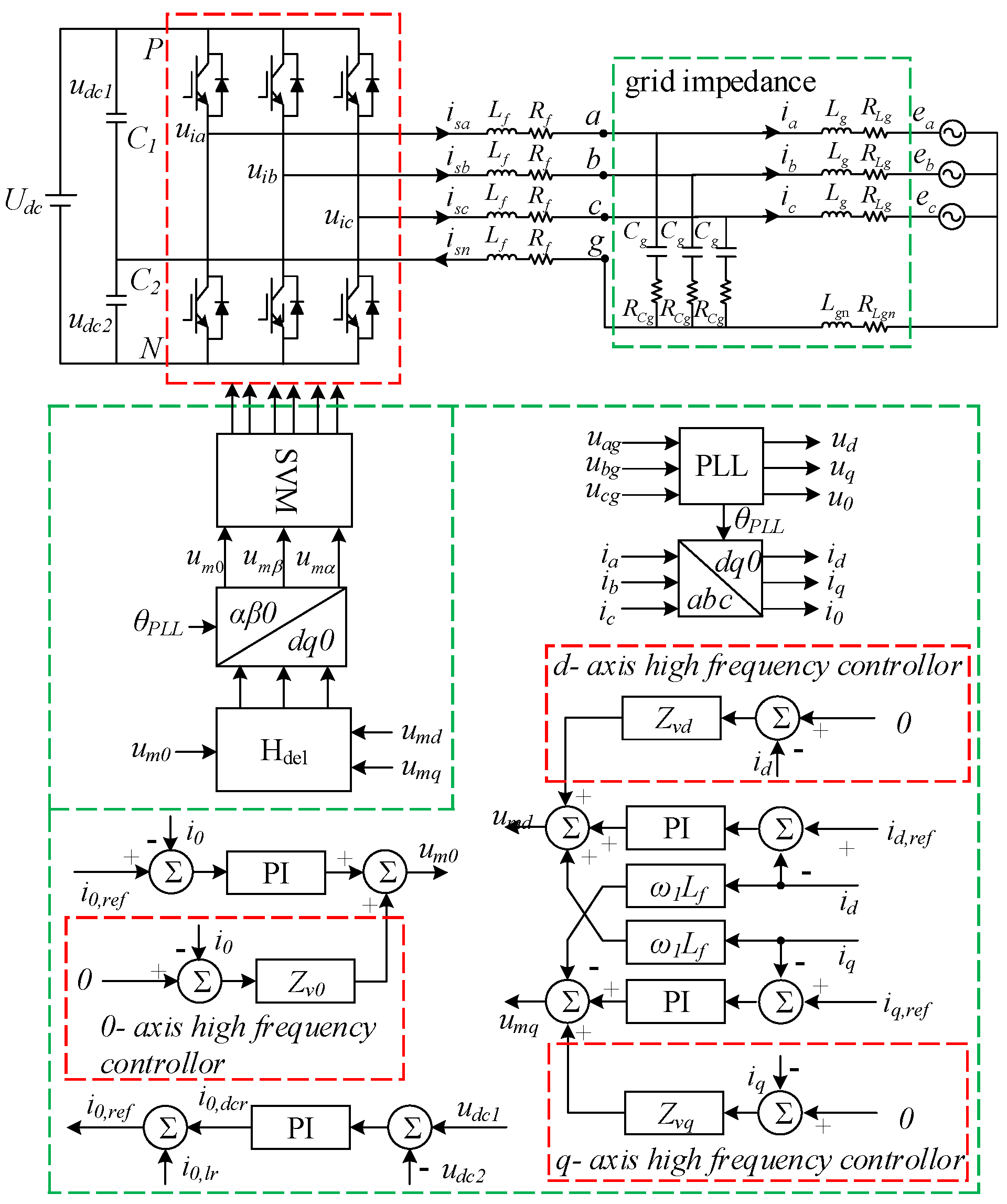
2.1. System Description

The block diagram of the TFSCI connected to the parallel compensation grid is shown in Figure 1. In Figure 1, Lf, Ln represent the filter inductors, Rf, Rfn represent the corresponding parasitic resistances. C1 and C2 are the DC side capacitors, where C1 = C2 = Cdc. Cg and RCg, respectively, represent the capacitance and parasitic resistance of the parallel compensation capacitor. Lg and RLg respectively, represents the inductance and parasitic resistance of transmission line.
The impedance of the grid can be achieved as follow [10,11,12],
{ Y g p = Y g n = 1 / Z g p = 1 / Z g n = R C g ( s L g + R L g ) + s C g R C g + 1 ( s L g + R L g ) ( s C g R C g + 1 ) Y g 0 = 1 / Z g 0 = s C g ( s ( L g + 3 L g n ) + R L g + 3 R L g n ) + 1 + s C g R C g ( 1 + s C g R C g ) ( s ( L g + 3 L g n ) + R L g + 3 R L g n )
Figure 2 shows the equivalent impedance of TFSCI and the grid. It is assumed that TFSCI can be considered as a current source Is,pn which is paralleled with the output impedance Zinv,pn0, while the grid can be considered as an ideal voltage source Vg,pn0 series with grid impedance Zg,pn0. where, Zg0, Zgp, Zgn represents zero-sequence impedance, positive-sequence impedance and negative-sequence impedance of grid, respectively.
Figure 3 shows the voltage, currents, active power and negative power of TFSCI connected to parallel compensation grid when the HFR occurs. The parameters can be seen in Table A1 in Appendix C. Figure 4 shows the FFT of ia. From Figure 3 and Figure 4, there are two resonance points at 365 Hz and 930 Hz in the system. From Figure 3 it can be found that the resonance at 431 Hz is caused by the zero-sequence components and the resonance at 930 Hz is caused by the positive-sequence and negative-sequence components. Therefore, in order to suppress these resonances, it is necessary to analyze how these resonances occurs.

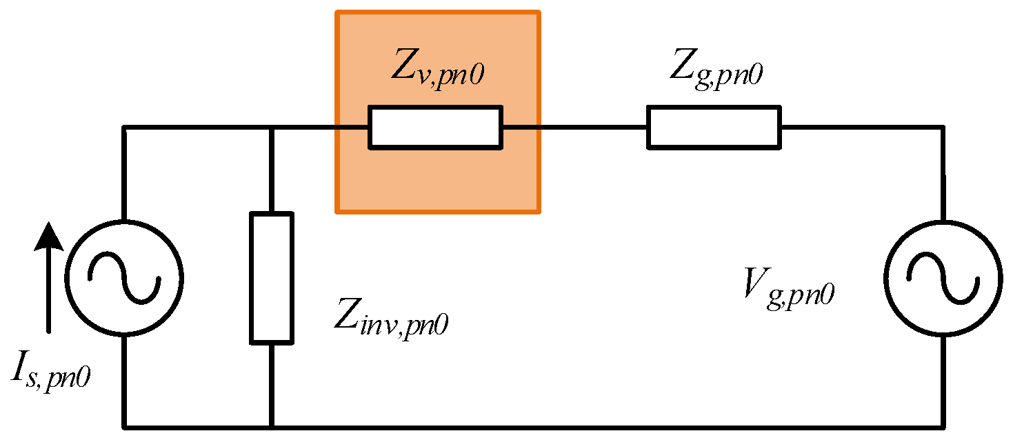
2.2. Simplified Impedance Modelling of TFSCI

In order to analyze how these HFR occurs clearly, some simplifications need to be done. Since the bandwidth of the PLL is usually within a few tens of hertz, the influence of the phase-locked loop on the impedance characteristics of the inverter can be ignored when studying the problem of high-frequency resonance [24].
After the simplification, the block diagram of the TFSCI impedance model can be shown in Figure 5. The detailed derivation process of Figure 5 can be seen in Appendix A.
In Figure 5, Hdec denotes the decoupling term matrix caused by the d-q decoupling control. Hci denotes the current controller matrix. Hdel denotes a delay transfer matrix caused by the control delay. Hiv denotes the relationship between current Δ i to Δ u d c 2 . Hvdc is the dc voltage balance PI controller to balance the up and down capacitor voltages.
H d e c = [ 0 ω 1 L f 0 ω 1 L f 0 0 0 0 0 ]
H d c = [ 1 / U d c 0 0 0 1 / U d c 0 0 0 1 / U d c ]
H d e l = [ e T d e l s 0 0 0 e T d e l s 0 0 0 e T d e l s ]
H c i = [ k d i p + k d i i s 0 0 0 k q i p + k q i i s 0 0 0 k 0 i p + k 0 i i s ]
H i v = [ 0 0 0 0 0 0 0 0 3 2 s C d c ]
H v d c = [ 0 0 0 0 0 0 0 0 k d c 0 i p + k d c 0 i i s ]
According to Figure 5, the admittance from Δ i to Δ u can be expressed as Equation (8). The detailed derivation process of Equation (8) can be seen in Appendix B.
{ Y p = 1 K m × ( 1 2 × ( k d i p + k d i i / ( s j ω 1 ) + k q i p + k q i i / ( s j ω 1 ) ) j ω 1 L f k d q ) + s L f + R f Y n = 1 K m × ( 1 2 × ( k d i p + k d i i / ( s j ω 1 ) + k q i p + k q i i / ( s j ω 1 ) ) + j ω 1 L f ) + s L f + R f Y z = 1 K m × ( k 0 i p + k 0 i i / s + 3 2 s C d c ( k 0 v p + k 0 v i / s ) ) + s ( 3 L n + L f ) + 3 R n + R f
where, K m = e T d e l s is the system delay. k0ip, k0ii, kqip, k0ii, k0ip, k0i represent respectively the proportional parameter and integral parameter of the d-axis, q-axis and 0-axis current PI controller, k0vp, k0vi represent the proportional parameter and integral parameter of DC voltage balance PI controller.
The Bode diagram of the inverter admittance after the simplification is shown in Figure 6. In Figure 6, Yp, Yn, and Y0 represents the admittance of the inverter after simplification, Ygp, Ygn and Yg0 are the admittance of the grid.
Based on the impedance stability theory, system stability is determined by Zinv,pn0/(Zinv,pn0 + Zg,pn0) [14]. When there is a lack of enough phase margin between Zinv,pn0 and Zg,pn0 at the amplitude intersection point, the resonance will occur. According to Figure 6, the positive-sequence impedance and negative-sequence impedance of the inverter are inductive at high frequency, the phase difference between the impedance of TFSCI and the impedance of grid is 178° close to 180° atamplitude intersection point 930 Hz. The zero-sequence impedance characteristic of the inverter the zero-sequence impedance characteristic gradually transitions from capacitive to inductive and the phase difference between the impedance of TFSCI and the impedance of grid is 176° close to 180° atamplitude intersection point 356 Hz. Figure 6 also reveals that the system has a risk of resonance at 356 Hz and 930 Hz. Combination of Figure 3, Figure 4 and Figure 5 and the above theoretical analysis, the following conclusions can be obtained,
(1)
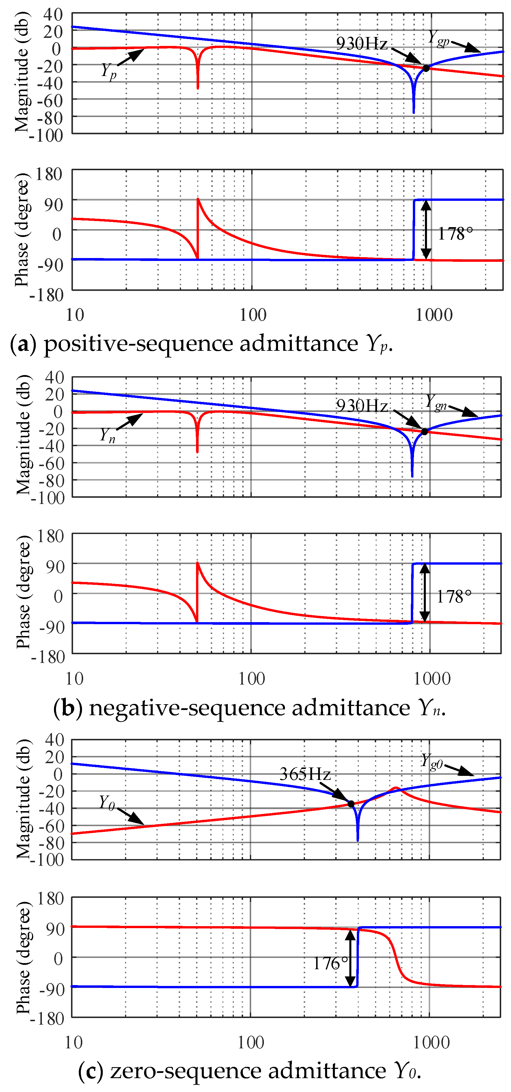
The reason of HFR in the TFSCI system is that the phase difference between the zero-sequence impedance, positive-sequence impedance and negative-sequence impedance of TFSCI and grid are close to 180°.
(2)
The simplified model obtained in this section can accurately reflect the high-frequency impedance of TFSCI and can be applied to the analysis and resolution of the high-frequency resonance.
Therefore, in order to suppress these resonances, it is necessary to reshapes the zero-sequence impedance, positive-sequence impedance and negative-sequence impedance of the TFSCI.
(1)
The reason of HFR in the TFSCI system is that the phase difference between the positive-sequence, negative-sequence, zero-sequence impedance of TFSCI system and grid is close to 180°.
(2)
The simplified model obtained in the previous section can accurately reflect the high-frequency impedance of TFSCI and can be used for the analysis and resolution of high-frequency problems.
Therefore, in order to suppress these resonances, it is necessary to reshapes the positive-sequence, negative-sequence and zero-sequence impedance of the TFSCI.

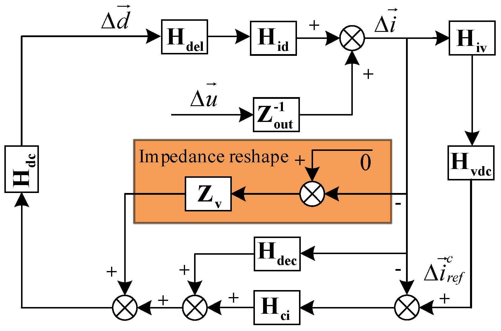
3. Control Strategy Based on Impedance Reshaping

Based on the analysis in Section 2, the key to maintain system stability is to ensure sufficient phase margin between the impedance of TFSCI and the impedance of grid. In other words, the phase of TFSCI system should be closed to 0°. Hence, an impedance reshaping strategy for TFSCI is proposed in this paper. In the proposed impedance reshaping strategy, a second-order high-pass filter and a negative second order differential block are introduced to reshape the zero-sequence impedances, positive-sequence impedances and negative-sequence impedances of TFSCI.
A high pass filter will be selected to ensure well performance of fundamental frequency control. The high pass filter is used to ensure a sufficiently large amplitude difference of TFSCI impedance between HFR frequency and fundamental frequency. It is vitally important to prevent fundamental frequency control from being influenced by the influence which is caused by the proposed HFR suppression controller. Considering the proposed control strategy is developed under the dq0 frame and the second-order filter is widely used in the industrial control, the second-order high-pass filter is selected.
In addition to the high-pass filter, a virtual impedance is needed to change the impedance of TFSCI. In order to reshape the phase of TFSCI impedance close to 0°, a virtual impedance Hv with resistive characteristic is needed. Figure 6 shows that the amplitude of TFSCI system impedance increases as the frequency increases, so it’s hard for a constant resistance to adapt the increasing impedance amplitude of the TFSCI. Based on this demand, a negative second-orders differential control (Hv) is used in this paper to adjust both the amplitude and phase of TFSCI impedance by means of its phase-frequency resistance characteristic. Therefore, the high-frequency controller can be expressed as follow,
Z v = G f i l t e r H v = s 2 / ( s 2 + 2 ζ ω c u t s + ω c u t 2 ) ( k s 2 )
where Gfilter is the second order high-pass filter, cut-off frequency fcut = 100 Hz. Hv= −ks2, in which Hv can be regarded as a resister whose resistance increases as the frequency increasing, k is the controller gain. Here ωcut = 2πfcut.
From the control block shown in Figure 1, the output reference voltage of the inverter consists of PI controller output, decoupled controller output and high frequency control output. So, the output reference voltage of the inverter can be shown in Equation (10). It should be noted that the purpose of the high frequency controller is to suppress the high frequency harmonic component in the system, so the reference currents i d , H F * , i q , H F * and i 0 , H F * of the high frequency controller are set to zero. In Equation (10), Gid, Giq and Gi0 represents d-axis, q-axis and 0-axis PI controller respectively. And Zvd, Zvq and Zv0 represents d-axis, q-axis and 0-axis high frequency controller respectively.
{ u m d = G i d ( i d * i d ) + Z v d ( i d , H F * i d ) j ω 1 L f i q + u d u m q = G i q ( i q * i q ) + Z v q ( i q , H F * i q ) + j ω 1 L f i d + u q u m 0 = G i 0 ( i 0 * i 0 ) + Z v 0 ( i 0 , H F * i 0 ) + u 0
According to Figure 6, the impedance after reshaping can be expressed as,
{ Y p = 1 K m ( 1 2 ( k d i p + k d i i / ( s j ω 1 ) + k q i p + k q i i / ( s j ω 1 ) ) j ω 1 L f k d q + G filter H v ) + s L f + R f Y n = 1 K m ( 1 2 ( k d i p + k d i i / ( s j ω 1 ) + k q i p + k q i i / ( s j ω 1 ) ) + j ω 1 L f + G filter H v ) + s L f + R f Y z = 1 K m ( k 0 i p + k 0 i i / s + 3 2 s C d c ( k 0 v p + k 0 v i / s ) + G filter H v ) + s ( 3 L n + L f ) + 3 R n + R f
It should be noted that not only three-phase four-wire inverters, but also three-phase three-wire photovoltaic inverters, wind turbines or energy storage inverters may also have the risk of high frequency resonance. Because the grid-connected devices show filter characteristic due to limited control bandwidth of the controller in high frequency range, and the parallel compensation grid respectively performs as the capacitance characteristic and inductance characteristic in different high frequency range, which will bring large phase angle difference between the impedance of the grid-connected devices and the impedance of the grid at amplitude intersection and results the high frequency resonance (HFR). The impedance reshaping method proposed in this paper can also be applied to these devices, because the essence of this method is equivalent to connecting a virtual resistor in series with the impedance of the high-frequency band of the grid-connected inverter by adding an extra current feedback branch into the control structure. Therefore, the damping of the grid-connected equipment is increased, the phase margin of the grid-connected system is improved, and the high-frequency resonance can be suppressed.

4. Analyses of Parameters Variation

In order to analyze the performance of the proposed method with different parameters, the performance of the proposed method under deviations of parameters is given in this section.

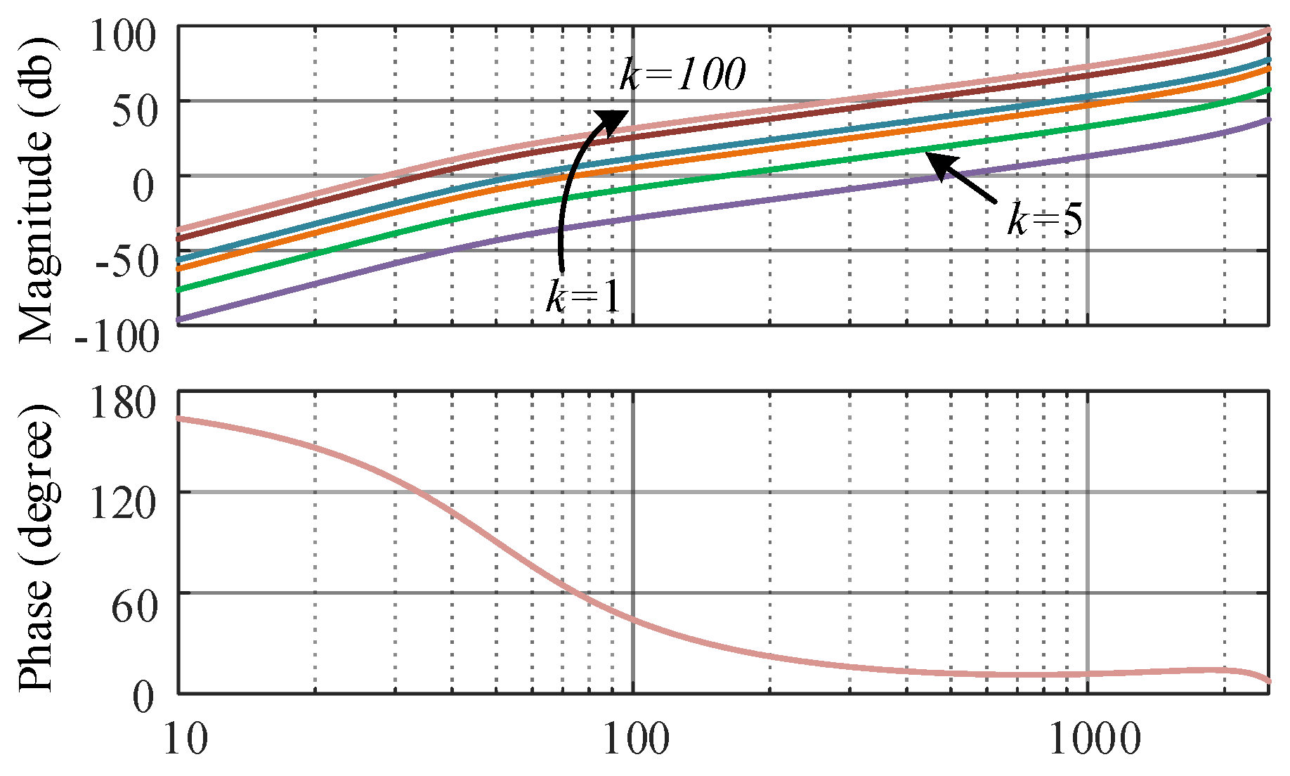
4.1. Choosing of High Frequency Controller Gain

In order to analyze the proposed control strategy and achieve well control performance, the analysis on high frequency controller k for the proposed control strategy is of vital importance, since k is decisive to high frequency suppression effect.
Figure 7 shows the Bode diagram of Hv with different controller gains. From Figure 7, it can be seen that increasing of the k can magnify the amplitude of Hv at high frequency; however, the magnitude at low frequency is also increased. At 50 Hz, GD is −43 dB and 17.7 dB when k = 1 and 100, which indicates that the overlarge k will affect the control performance at the fundamental frequency. Figure 8 shows the bode diagram of TFSCI’s reshaped impedance with different values of k, which validates the above analyses that overlarge k will affect the fundamental frequency control performance. The TFSCI system parameters used in the analyses are shown in Table A1 in Appendix C.
From Figure 7, when k = 5, the magnitude of Hv at 50 Hz is −23 dB, which means the high frequency controller can hardly affect the fundamental frequency control performance. From Figure 8, when kd = kq = k0 = 5, the high frequency controller shows well reshaping effect on the impedance of the inverter, which ensures at least 30°phase margin in the system. So, choose kd = kq = k0 = 5 as the high frequency controller gain of d-axis, q-axis and 0-axis.

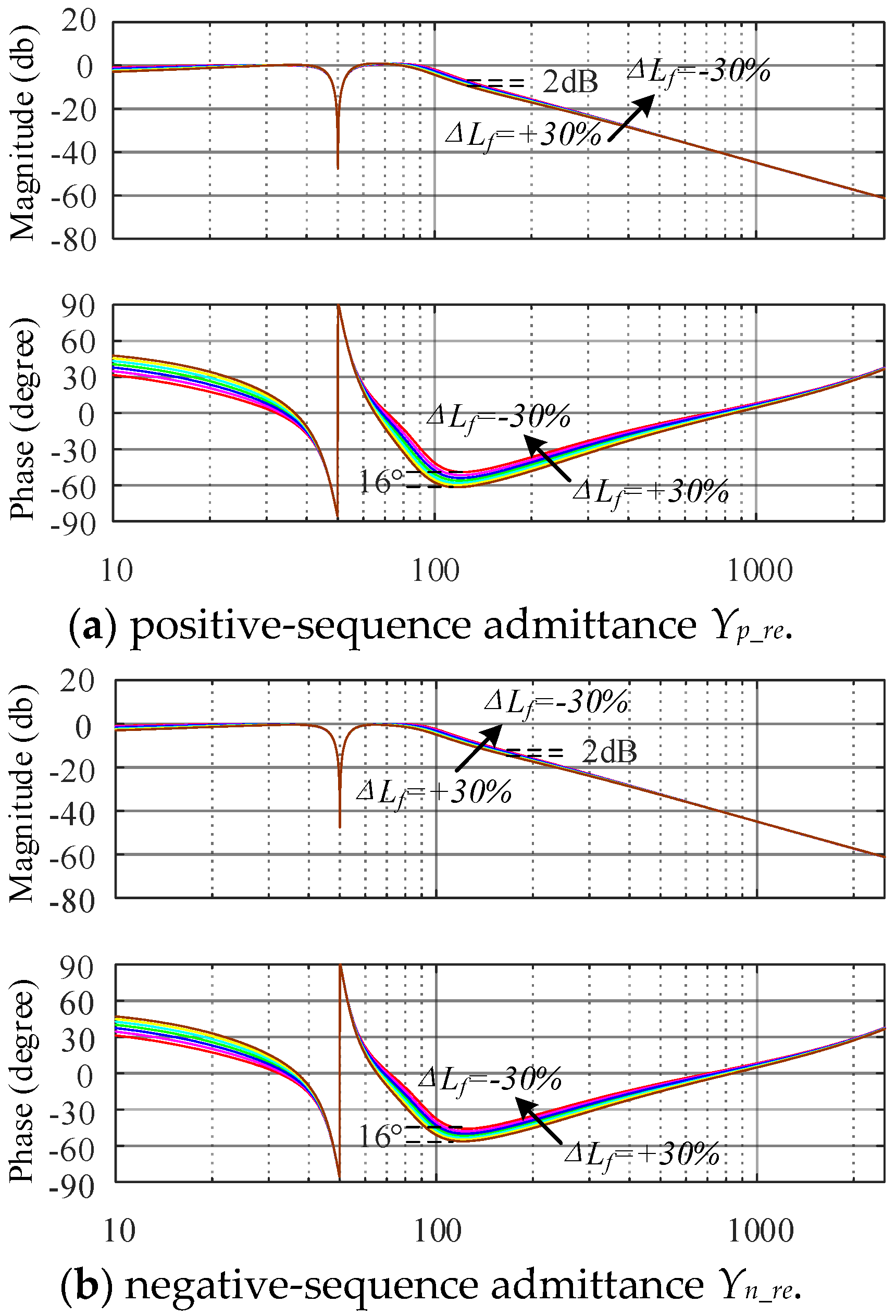
4.2. Filter Parameters Deviations

In the actual operation of the inverter, due to the deviation between the actual inductance value and the nominal inductance value, it is necessary to analyze the influence of the variation of the filter inductance value on the impedance reshaping effect. The following figure shows the impedance reshaping effect with ±30% deviation of the filter inductor Lf. It can be seen from Figure 9 that the inductance deviation basically hardly affects the impedance reshaping effect.

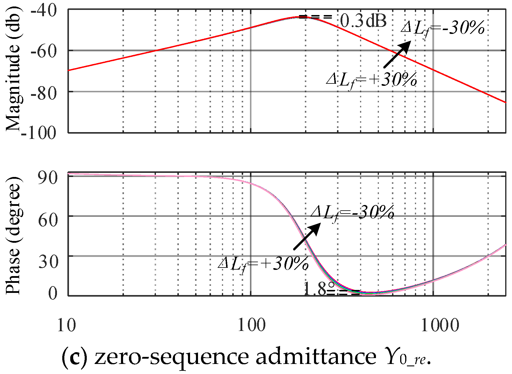
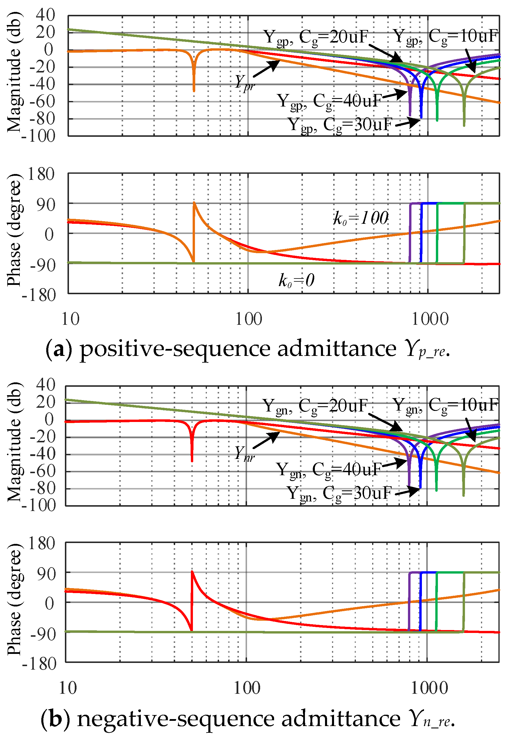
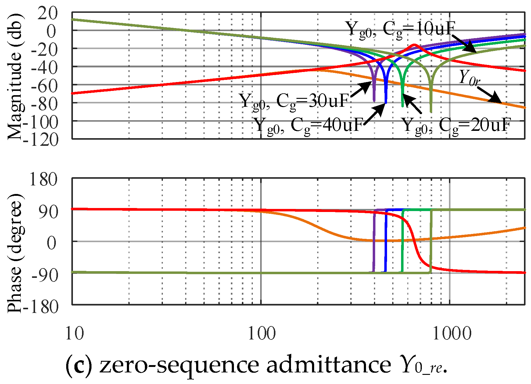
4.3. Parallel Compensation Degree Variations

In the actual grid operation, the parallel compensation degree of the grid will change with the actual demand. The following figure shows the suppression effect of the proposed impedance reshaping method on HFR when the parallel compensation of the power grid changes. It can be seen from Figure 10 that even if the degree of parallel compensation changes, the proposed impedance reshaping method can still ensure sufficient phase margin for the inverter impedance to effectively suppress HFR.

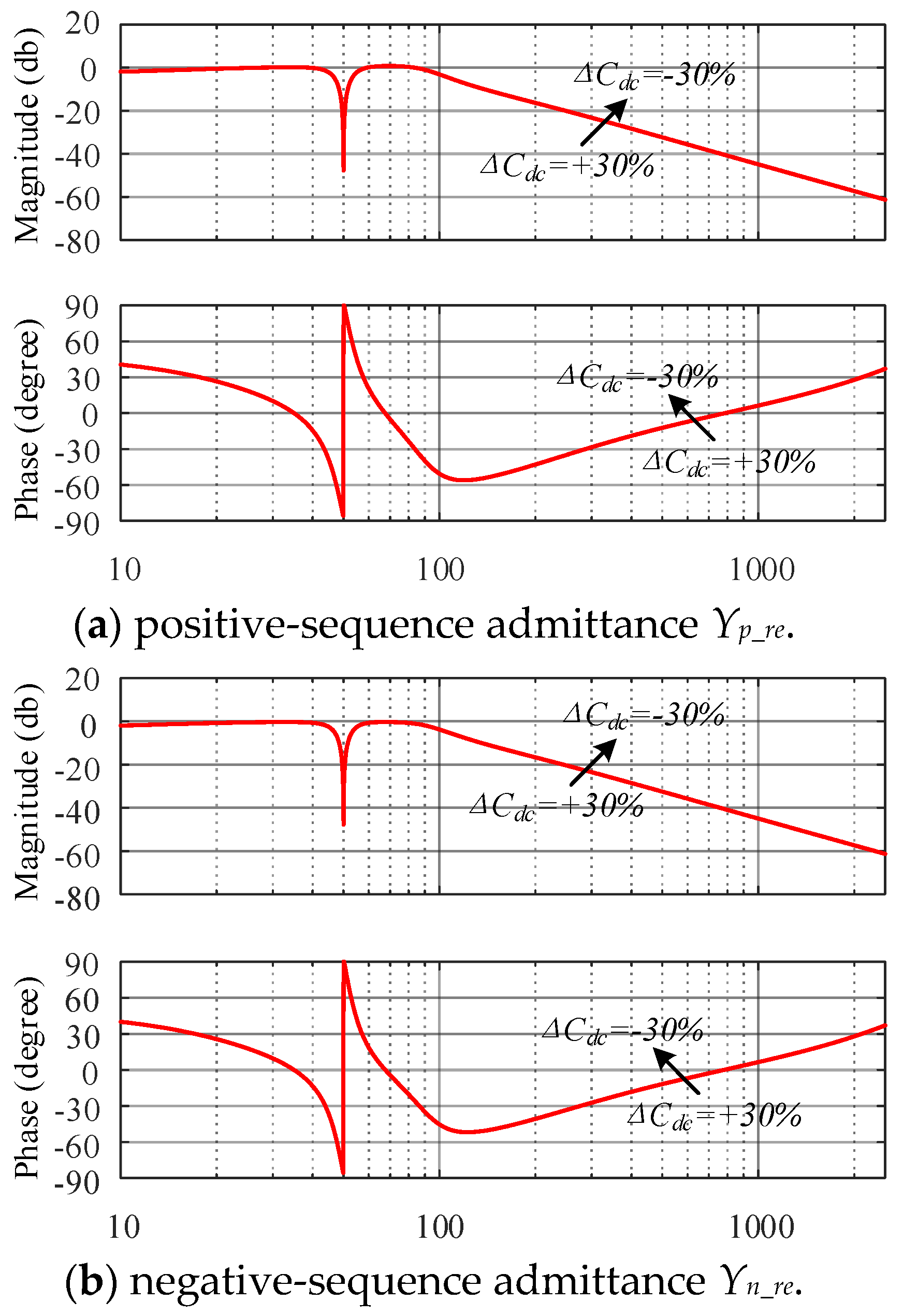
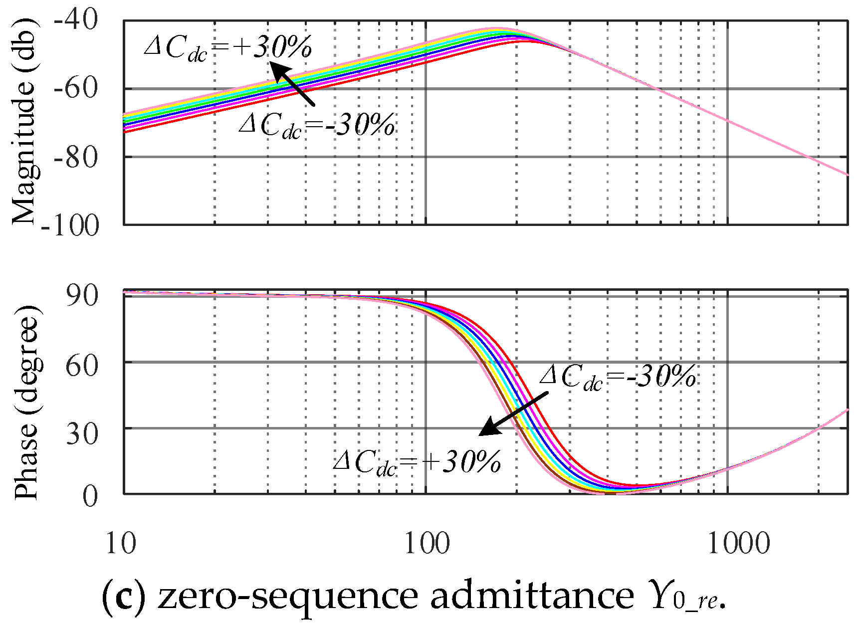
4.4. Dc Side Capacitance Variations

In the actual operation of the inverter, due to the deviation between the actual capacitance value and the nominal capacitance value, it is necessary to analyze the influence of the variation of the DC side capacitance value on the impedance reshaping effect. The following figure shows the impedance reshaping effect with ±30% deviation of the DC side capacitance Cdc. It can be seen from Figure 11 that the capacitance deviation basically hardly affects the impedance reshaping effect.

4.5. Discussion of Non-Linearities System

It should be noted that the above analyses are based on the grid impedance presented in Figure 1. It is worth discussing whether the proposed control method is still effective if there are non-linearities devices connected to the system.
The high frequency resonance studied in this paper is caused by the small signal instability when the three-phase four-wire split capacitor inverter is connected to the parallel compensation grid. The high frequency resonance suppression method proposed in this paper is also realized based on impedance reshaping under small signal. So, the whole system can be linearized is a basis of this paper.
In fact, when the system reaches stable working state, the devices can be linearized, whether it is a power electronic device, a motor or other device with nonlinear characteristics based on the stable working state. Under this premise, regardless of whether there are nonlinear devices in the grid, the grid impedance and device impedance can be aggregated into an equivalent impedance by linearizing. Then, the Bode diagram of equivalent impedance is similar to that of grid impedance shown in Figure 6 in the paper. The high-frequency resonance suppression method proposed in this paper is to change the impedance characteristics of the inverter in the high-frequency band from pure capacitive or pure inductive to pure resistive, which increases the damping of the system. So even if there are nonlinear devices in the system, it will not affect the effectiveness of the proposed method. In addition, the grid impedance model used in this paper is an extreme case, which has both purely capacitive and purely inductive characteristics in different frequency bands of grid impedance. Therefore, the proposed control method is still effective in non-linearities system

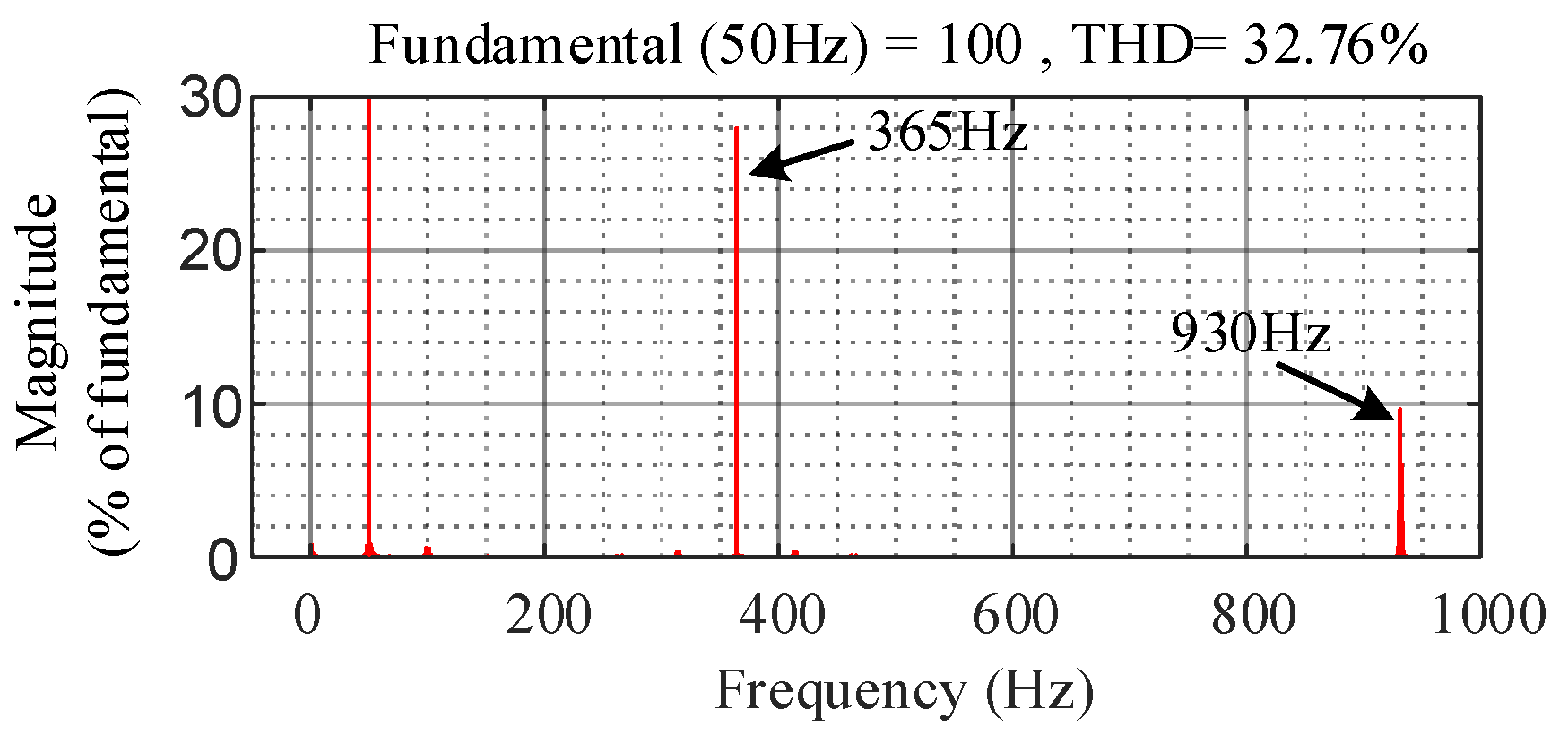
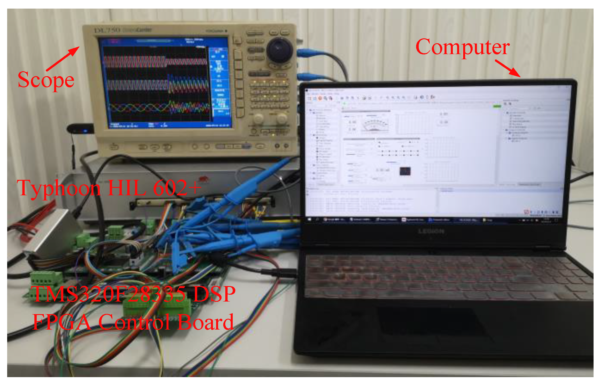
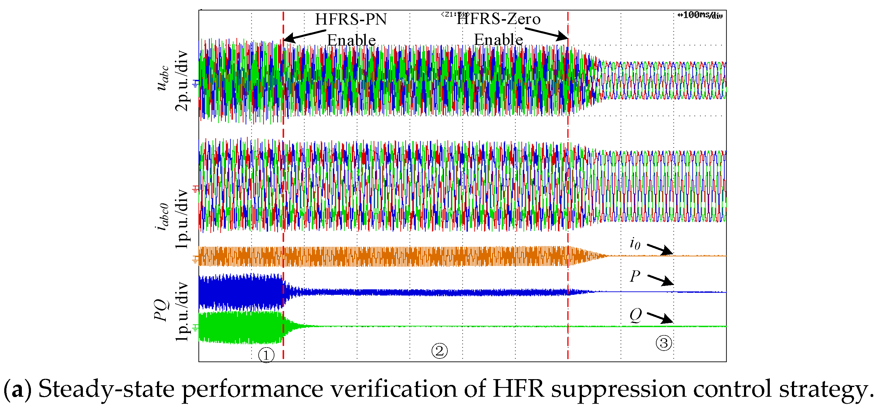
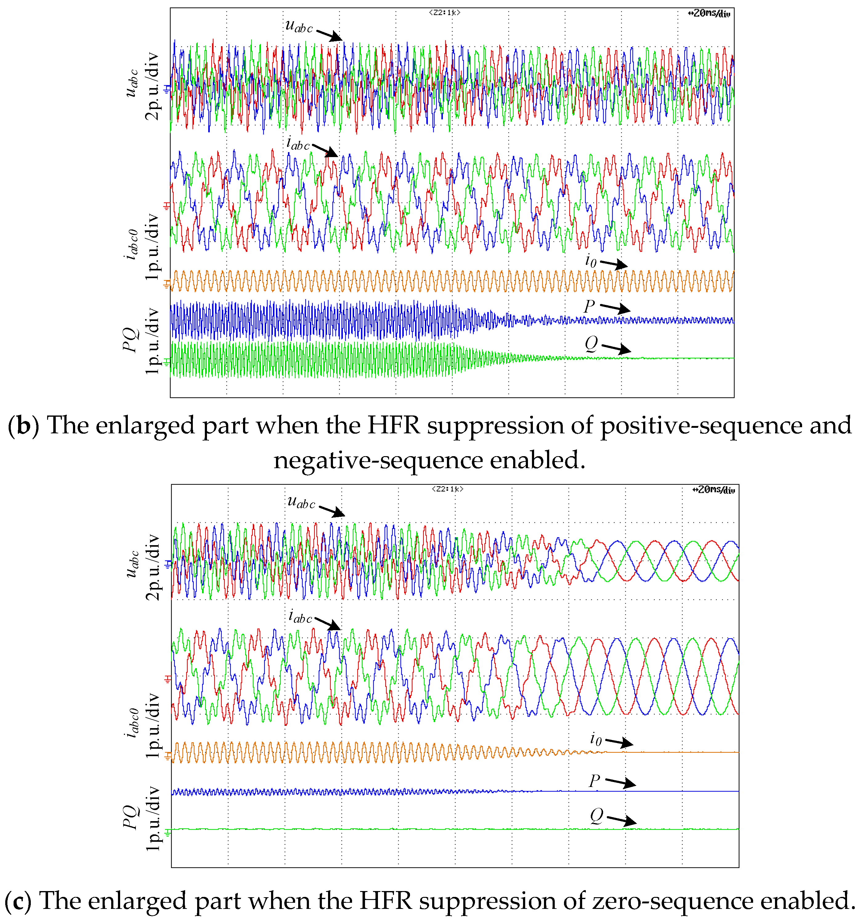
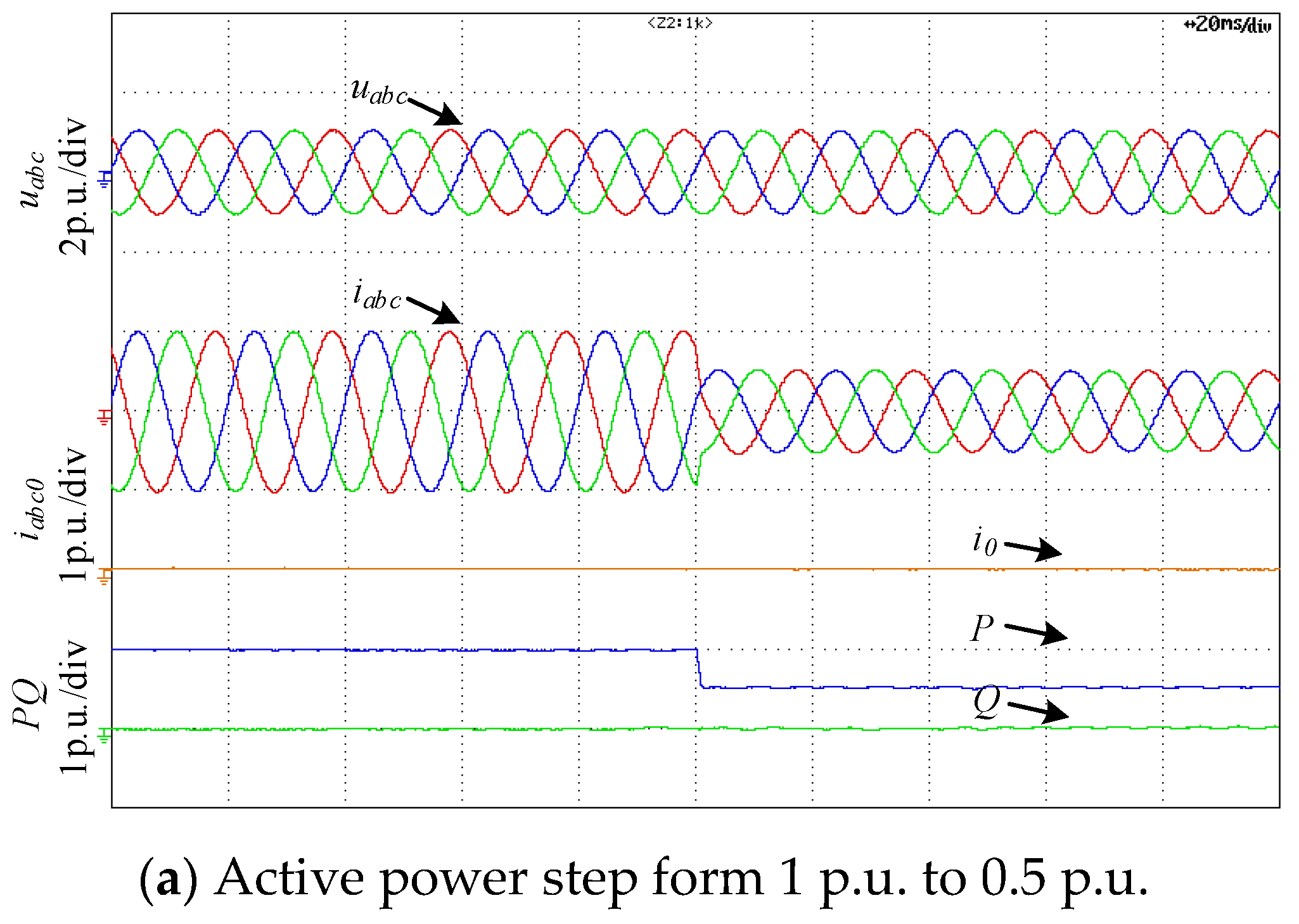
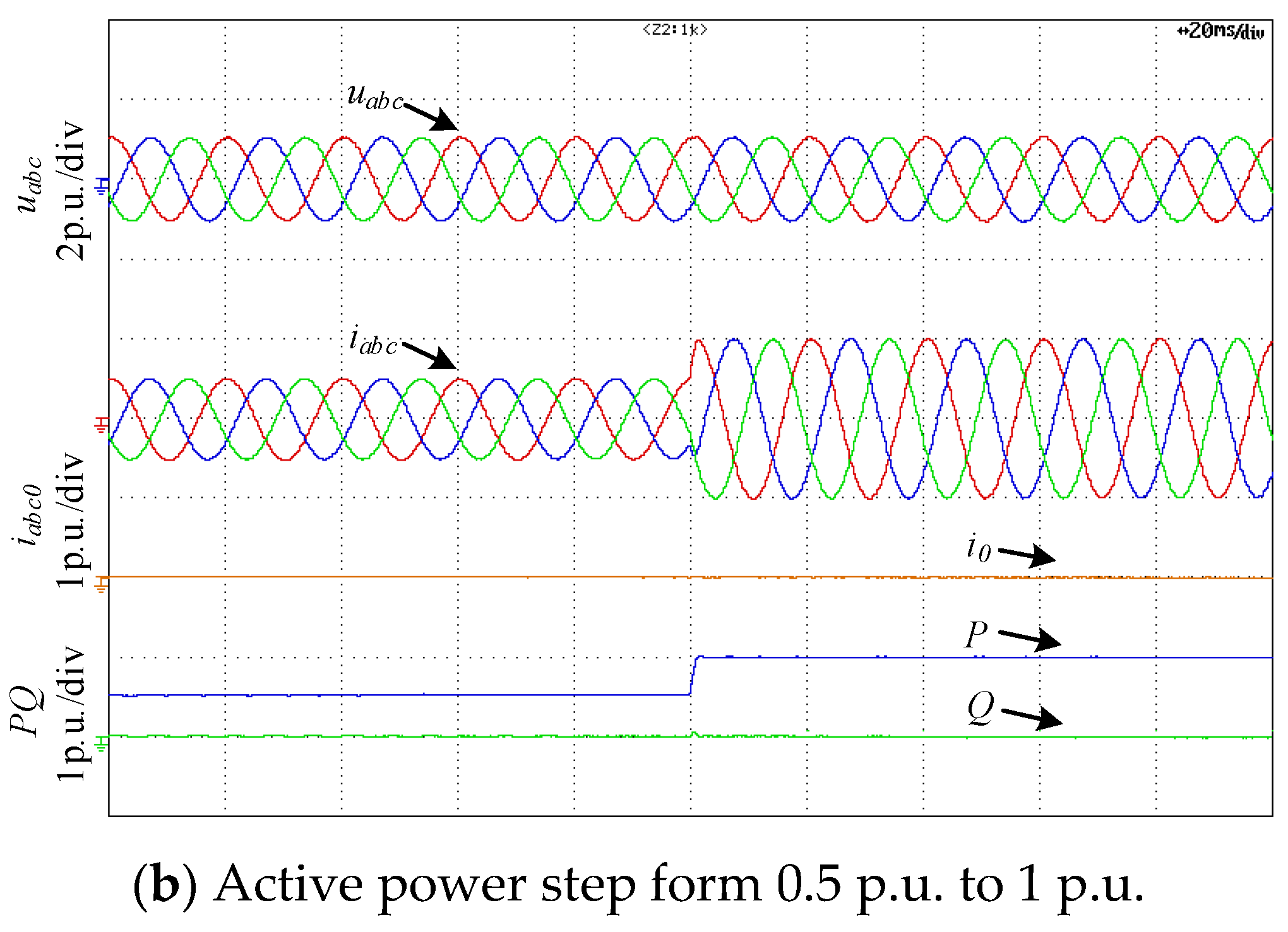
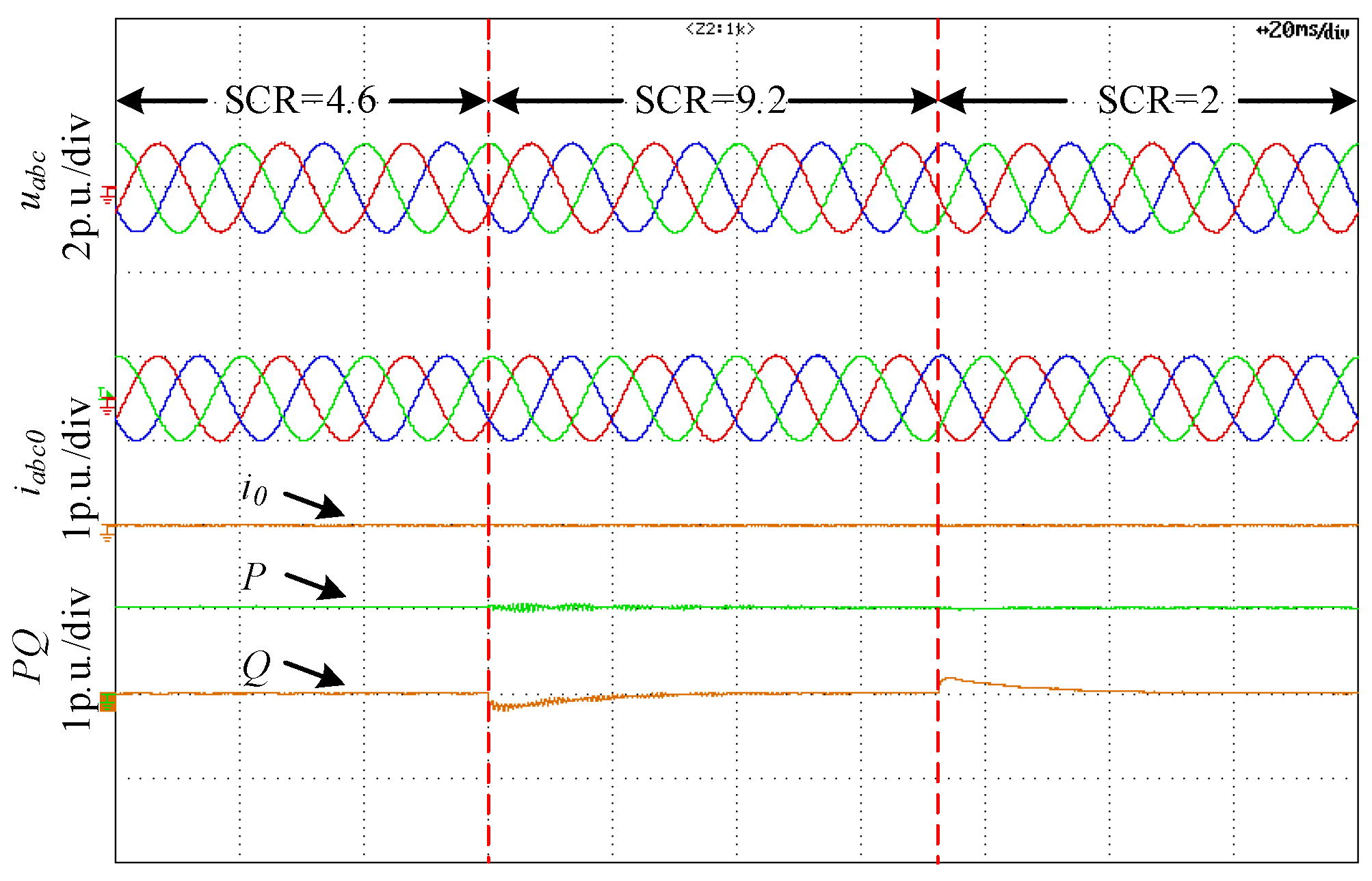
5. Experimental Verification

To better verify the achieved conclusions, the hardware platform based on Control-hardware-in-loop (CHIL) is established, which can be seen in Figure 12. The model of three-phase four-wire split capacitor Grid-connected inverter system is established in Typhoon 602+ with the time step of 1 μs. The controllers of the three-phase four-wire split capacitor inverter are carried out in a TMS320F28335/Spartan6 XC6SLX16 DSP+FPGA control board. And the CHIL has been used to analyze and verify the conclusion presented in [27,28]. The parameters of the system are listed in Table A1 in section Appendix C.
Figure 13 shows the Steady-state performance verification of HFR suppression control strategy. There are three stages in Figure 13a. State ① shows the voltages, currents, active power and reactive power of the TFSCI when HFR occurs. It can be seen that there are high frequency harmonics in the inverter’s voltages, currents, active power and reactive power. State ② shows waveforms when only HFR suppression of positive-sequence and negative-sequence is enabled. It can be seen that the resonance caused by the positive-sequence and negative-sequence components is well suppressed after enabling the HFR suppression of positive-sequence and negative-sequence. However, there are still high-frequency resonance caused by zero-sequence component in the system. State ③ shows the waveforms after further enabling HFR suppression of zero-sequence, which shows that the resonance caused by the zero-sequence component has been well suppressed.
Figure 13b shows the enlarged part when the HFR suppression of positive-sequence and negative-sequence enabled. Figure 13c shows the enlarged part when the HFR suppression of zero-sequence enabled. From Figure 13b,c, it can be seen that the HFR can be suppressed within 50 ms after the proposed HFR suppression strategy enabled, which demonstrates that the proposed HFR strategy is provided with well dynamic performance.
Figure 14 shows the effect of HFR control strategy on the dynamic performance of fundamental frequency control. Figure 14a shows the voltages, currents of and powers of the TFSCI when the active power step form 1 p.u. to 0.5 p.u., Figure 14b shows the voltages, currents of and powers of the TFSCI when the active power step form 0.5 p.u. to 1 p.u. It can be seen from Figure 14 that the proposed control strategy hardly has negative effect on the dynamic performance of fundamental frequency.
Figure 15 shows the adaptability verification of the proposed control strategy to the variation of the power grid short-circuit ratio. Figure 15 shows the voltage, current, and power waveforms of the inverter when the short-circuit ratio of the grid changes from 4.6 to 9.2 and the short-circuit ratio changes from 9.2 to 2. When the short-circuit ratio changes, the inverter can still remain stable and well HFR suppression performance, indicating that the proposed high-frequency oscillation control strategy has strong adaptability to the changes in the grid impedance.

6. Conclusions

This paper studies the HFR issue when the TFSCI connects to parallel compensation grid. The conclusions achieved by this paper can be shown as following.
(1)
From the perspective of impedance, the essence which causes the HFR is the insufficient phase margin at the intersection of positive-sequence, negative-sequence, and zero-sequence impedance amplitude between TFSCI and grid based on a simplifying impedance of the TFSCI, when the TFSCI connects to the grid.
(2)
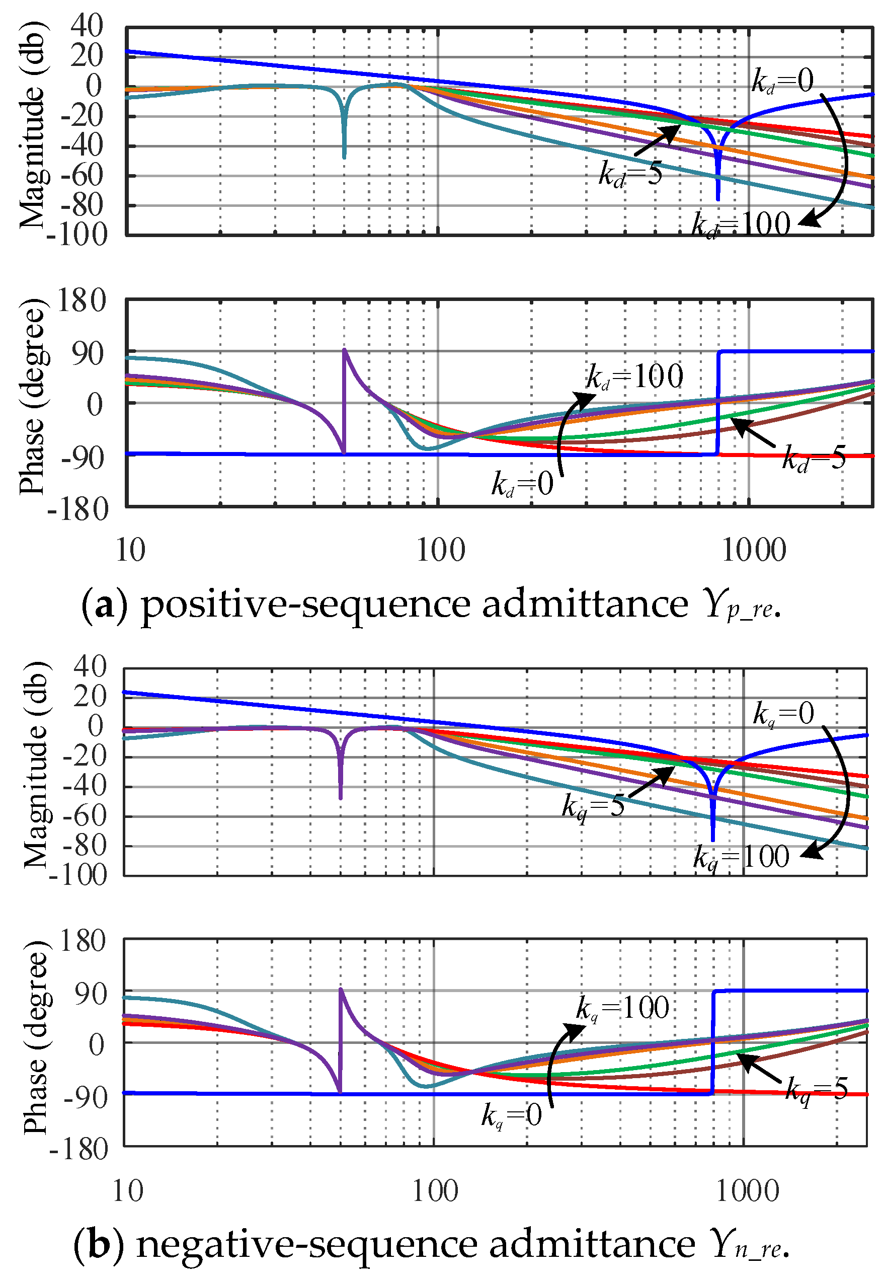
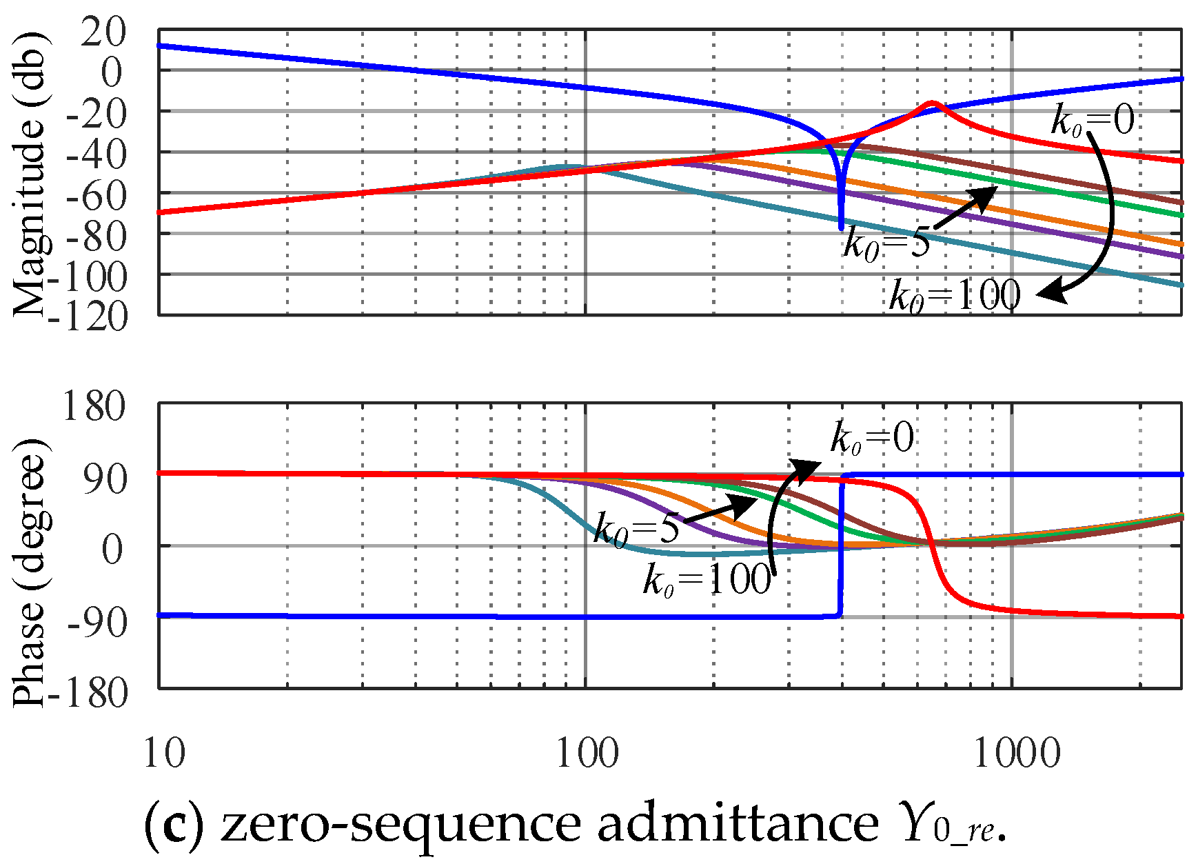
In order to suppress the HFR, an impedance reshaping method has been proposed in this paper. This method can reshape the amplitude and phase of the TFSCI impedance in high frequency band without affecting the performance of fundamental frequency control and ensure that the system has sufficient phase margin.
(3)
The impedance reshaping method can reshape the impedance of TFSCI within wide frequency range which makes it able to cope with the challenge of the parallel compensation degree change.

Author Contributions

Conceptualization, G.F.; Methodology, Z.Y.; Project administration, Y.X. and H.N.; Resources, H.N.; Software, L.H.; Validation, Z.W.; Writing—original draft, G.F. All authors have read and agreed to the published version of the manuscript.

Funding

This research was funded by [the Naitional Natural Science Fundamentation of China] grant number [51507183, 51877212].

Institutional Review Board Statement

Not applicable.

Informed Consent Statement

This research article describing a study dosen’t involving humans.

Data Availability Statement

Not applicable.

Acknowledgments

This project is supported by the Naitional Natural Science Fundamentation of China (51507183, 51877212).

Conflicts of Interest

The authors declare no conflict of interest.

Appendix A

Figure A1 shows the small-signal circuit model of inverter in dq0-domain.
Figure A1. Small-signal circuit model of inverter in dq0-domain. (a) d-axis small-signal circuit; (b) q-axis small-signal circuit; (c) 0-axis small-signal circuit. Reproduced from [26] IEEE Access 2021.
Energies 15 01486 g0a1
From Figure A1, assuming Δ d d s = Δ d q s = 0 the transfer function matrix from perturbation voltage to current response in the system frame can be expressed as,
Z o u t = [ s L f + R f ω L f 0 ω L f s L f + R f 0 0 0 s ( L f + 3 L n ) + R f + 3 R n 3 2 s C ]
Similarly, in Figure A1, assuming Δ u d s = Δ u q s = 0 the transfer function matrix from duty ratio to the corresponding current response in the system frame can be expressed as,
H i d = [ ( s L f + R f ) U d c ( s L f + R f ) 2 + ( ω L f ) 2 b = ω L f U d c ( s L f + R f ) 2 + ( ω L f ) 2 0 ω L f U d c ( s L f + R f ) 2 + ( ω L f ) 2 ( s L f + R f ) U d c ( s L f + R f ) 2 + ( ω L f ) 2 0 0 0 U d c s ( 3 L n + L f ) + 3 R n + R f 3 2 s C ]
Additionally, through Kirchhoff’s current law, the zero-sequence current can be written as,
i 0 = C f 3 d ( u c 2 u c 1 ) d t
Then, matric Hiv can be achieved as follow,
H i v = [ 0 0 0 0 0 0 0 0 3 2 s C d c ]
Matrix Hvdc represents the dc voltage balance PI controller to balance the up and down capacitor voltages, which can be expressed as follow,
H v d c = [ 0 0 0 0 0 0 0 0 k d c 0 i p + k d c 0 i i s ]
Then, ignoring the influence of the SRF-PLL and considering time delay Hdel, current controller Hci and the d-q decoupling control Hdec, the impedance model block diagram of the three-phase four-wire split capacitor inverter can be obtained as shown in Figure 6.
H d e l = [ e T d e l s 0 0 0 e T d e l s 0 0 0 e T d e l s ]
H d e c = [ 0 ω 1 L f 0 ω 1 L f 0 0 0 0 0 ]
H c i = [ k d i p + k d i i s 0 0 0 k q i p + k q i i s 0 0 0 k 0 i p + k 0 i i s ]

Appendix B

According to Figure 6, when the proposed HFR suppression strategy is not enabled which means the branch containing Zv is opened. So, the admittance from Δ i to Δ u can be obtained as,
Y i d q 0 = Z o u t - 1 I - H i d H d e l H d c ( H d e c - H c i ) H d c H c i H i v H v d c H i d H d e l
By reference [29], the admittance in the d-q-0 domain can be equivalently transformed into the admittance in sequence domain as,
Y ipn 0 = T Z Y d q 0 T Z 1 = [ Y i p n 0 0 Y i 0 ] = [ Y 11 Y 12 0 Y 21 Y 22 0 0 0 Y 33 ]
where,
T Z = 1 2 [ 1 j 0 1 j 0 0 0 2 ]
Taking the responding matrixes to above equation, then Equation (8) can be can be achieved.

Appendix C

Table A1. Three-phase Four-wire Split Capacitor Grid-connected Inverter Parameters.
SymbolParameterValue
UsRated voltage380 V
PnRated power30 kW
f1Fundamental frequency50 Hz
fsSwitching frequency5 kHz
LfFilter inductance3 mH
RLfparasitic resistance of filter inductance0.02 Ω
LgGrid inductance1 mH
RLgaparasitic resistance of Grid inductance0.02 Ω
kppProportional gain of PLL controller0.16
kpiIntegral gain of PLL controller0.25
kdipProportional gain of d-axis current controller1
kdiiIntegral gain of d-axis current controller18
kqipProportional gain of q-axis current controller1
kqiiIntegral gain of q-axis current controller18
k0ipProportional gain of zero-axis current controller3
k0iiIntegral gain of zero-axis current controller54
kdcpproportional parameter of DC voltage balance PI controller2.1
kdciintegral parameter of DC voltage balance PI controller4.2

References

  1. Primadianto, A.; Lu, C.-N. A Review on Distribution System State Estimation. IEEE Trans. Power Syst. 2016, 32, 3875–3883. [Google Scholar] [CrossRef]
  2. Ahmad, F.; Rasool, A.; Ozsoy, E.; Sekar, R.; Sabanovic, A.; Elitaş, M. Distribution system state estimation-A step towards smart grid. Renew. Sustain. Energy Rev. 2018, 81, 2659–2671. [Google Scholar] [CrossRef] [Green Version]
  3. Cavraro, G.; Arghandeh, R. Power distribution network topology detection with time-series signature verification method. IEEE Trans. Power Syst. 2018, 33, 3500–3509. [Google Scholar] [CrossRef]
  4. Bifaretti, S.; Lidozzi, A.; Solero, L.; Crescimbini, F. Modulation with Sinusoidal Third-Harmonic Injection for Active Split DC-Bus Four-Leg Inverters. IEEE Trans. Power Electron. 2015, 31, 6226–6236. [Google Scholar] [CrossRef]
  5. Hirve, S.; Chatterjee, K.; Fernandes, B.G.; Imayavaramban, M.; Dwari, S. PLL-Less Active Power Filter Based on One-Cycle Control for Compensating Unbalanced Loads in Three-Phase Four-Wire System. IEEE Trans. Power Deliv. 2007, 22, 2457–2465. [Google Scholar] [CrossRef] [Green Version]
  6. Morais, A.; Tofoli, F.L.; Barbi, I. Modeling, Digital Control, and Implementation of a Three-Phase Four-Wire Power Converter Used as A Power Redistribution Device. IEEE Trans. Ind. Inf. 2016, 12, 1035–1042. [Google Scholar] [CrossRef]
  7. Kerekes, T.; Teodorescu, R.; Liserre, M.; Klumpner, C.; Sumner, M. Evaluation of Three-Phase Transformerless Photovoltaic Inverter Topologies. IEEE Trans. Power Electron. 2009, 24, 2202–2211. [Google Scholar] [CrossRef]
  8. Lliuyacc, R.; Mauricioa, J.; Gomez-Exposito, A.; Savaghebi, M.; Guerrero, J. Grid-forming VSC control in four-wire systems with unbalanced nonlinear loads. Elect. Power Syst. Res. 2017, 152, 249–256. [Google Scholar] [CrossRef] [Green Version]
  9. Carlos, G.; Jacobina, C.B.; Santos, E. Investigation on Dynamic Voltage Restorers with Two DC Links and Series Converters for Three-Phase Four-Wire Systems. IEEE Trans. Ind. Appl. 2016, 52, 1608–1620. [Google Scholar] [CrossRef]
  10. Ahmed, E.M.; Aly, M.; Elmelegi, A.; Ali, Z.M. Multifunctional Distributed MPPT Controller for 3P4W Grid-Connected PV Systems in Distribution Network with Unbalanced Loads. Energies 2019, 12, 4799. [Google Scholar] [CrossRef] [Green Version]
  11. Zieliński, D.; Stefańczak, B.; Jędrys, K. Phase-Independent Reactive Power Compensation Based on Four-Wire Power Converter in the Presence of Angular Asymmetry between Voltage Vectors. Energies 2022, 15, 497. [Google Scholar] [CrossRef]
  12. Shukla, A.; Ghosh, A.; Joshi, A. Hysteresis current control operation of flying capacitor multilevel inverter and its application in shunt compensation of distribution systems. IEEE Trans. Power Deliv. 2007, 22, 396–405. [Google Scholar] [CrossRef] [Green Version]
  13. Ramos-Carranza, H.A.; Medina, A.; Chang, G.W. Real-Time Shunt Active Power Filter Compensation. IEEE Trans. Power Deliv. 2008, 23, 2623–2625. [Google Scholar] [CrossRef]
  14. Wandhareand, R.G.; Agarwal, V. Reactive power capacity enhancement of a PV-grid system to increase PV penetration level in smart grid scenario. IEEE Trans. Smart Grid 2014, 5, 1845–1854. [Google Scholar] [CrossRef]
  15. Ren, Y.; Wang, X.; Chen, L.; Min, Y.; Li, G.; Wang, L.; Zhang, Y. A Strictly Sufficient Stability Criterion for Grid-Connected Converters Based on Impedance Models and Gershgorin’s Theorem. IEEE Trans. Power Deliv. 2020, 35, 1606–1609. [Google Scholar] [CrossRef]
  16. Song, S.; Guan, P.; Liu, B.; Lu, Y.; Goh, H. Impedance Modeling and Stability Analysis of DFIG-Based Wind Energy Conversion System Considering Frequency Coupling. Energies 2021, 14, 3243. [Google Scholar] [CrossRef]
  17. Xu, Y.; Nian, H.; Wang, Y.; Sun, D. Impedance Modeling and Stability Analysis of VSG Controlled Grid-Connected Converters with Cascaded Inner Control Loop. Energies 2020, 13, 5114. [Google Scholar] [CrossRef]
  18. Cespedes, M.; Sun, J. Impedance Modeling and Analysis of Grid-Connected Voltage-Source Converters. IEEE Trans. Power Electron. 2013, 29, 1254–1261. [Google Scholar] [CrossRef]
  19. Sun, J. Impedance-Based Stability Criterion for Grid-Connected Inverters. IEEE Trans. Power Electron. 2011, 26, 3075–3078. [Google Scholar] [CrossRef]
  20. Wang, X.; Blaabjerg, F.; Chen, Z. Synthesis of variable harmonic impedance in inverter-interfaced distributed generation unit for harmonic damping throughout a distribution network. IEEE Trans. Ind. Appl. 2012, 48, 1407–1417. [Google Scholar] [CrossRef] [Green Version]
  21. Wang, X.; Blaabjerg, F.; Chen, Z. Autonomous control of inverter interfaced distributed generation units for harmonic current filtering and resonance damping in an islanded microgrid. IEEE Trans. Ind. Appl. 2014, 50, 452–461. [Google Scholar] [CrossRef]
  22. Wang, X.; Pang, Y.; Loh, P.C.; Blaabjerg, F. A Series-LC-Filtered Active Damper with Grid Disturbance Rejection for AC Power-Electronics-Based Power Systems. IEEE Trans. Power Electron. 2014, 30, 4037–4041. [Google Scholar] [CrossRef]
  23. Wang, X.; Blaabjerg, F.; Liserre, M. An active damper to suppress multiple resonances with unknown frequencies. In Proceedings of the 2014 IEEE Applied Power Electronics Conference and Exposition—APEC 2014, Fort Worth, TX, USA, 16–20 March 2014. [Google Scholar] [CrossRef] [Green Version]
  24. Pang, B.; Wu, C.; Nian, H.; Blaabjerg, F. Damping Method of High-Frequency Resonance for Stator Current Controlled DFIG System Under Parallel Compensation Grid. IEEE Trans. Power Electron. 2020, 35, 10260–10270. [Google Scholar] [CrossRef]
  25. Wang, X.; Li, Y.; Blaabjerg, F.; Loh, P.C. Virtual-impedance-based control for voltage-source and current-source converters. IEEE Trans. Power Electron. 2015, 30, 7019–7037. [Google Scholar] [CrossRef]
  26. Nian, H.; Liao, Y.; Li, M.; Sun, D.; Xu, Y.; Hu, B. Impedance Modeling and Stability Analysis of Three-Phase Four-Leg Grid-Connected Inverter Considering Zero-Sequence. IEEE Access 2021, 9, 83676–83687. [Google Scholar] [CrossRef]
  27. Hu, B.; Nian, H.; Yang, J.; Li, M.; Xu, Y. High-Frequency Resonance Analysis and Reshaping Control Strategy of DFIG System Based on DPC. IEEE Trans. Power Electron. 2020, 36, 7810–7819. [Google Scholar] [CrossRef]
  28. Nian, H.; Yang, J.; Hu, B.; Jiao, Y.; Xu, Y.; Li, M. Stability Analysis and Impedance Reshaping Method for DC Resonance in VSCs-based Power System. IEEE Trans. Energy Convers. 2021, 36, 3344–3354. [Google Scholar] [CrossRef]
  29. Rygg, A.; Molinas, M.; Zhang, C.; Cai, X. A Modified Sequence-Domain Impedance Definition and Its Equivalence to the dq-Domain Impedance Definition for the Stability Analysis of AC Power Electronic Systems. IEEE J. Emerg. Sel. Top. Power Electron. 2016, 4, 1383–1396. [Google Scholar] [CrossRef] [Green Version]
Figure 1. Block diagram of three-phase four-wire split capacitor inverter.
Energies 15 01486 g001
Figure 2. Equivalent impedance of TFSCI system and grid.
Energies 15 01486 g002
Figure 3. Voltage and currents of TFSCI when HFR occurs.
Energies 15 01486 g003
Figure 4. FFT result of ia when HFR occurs.
Energies 15 01486 g004
Figure 5. The block diagram of the TFSCI impedance model.
Energies 15 01486 g005
Figure 6. Admittance model of TFSCI after simplification.
Energies 15 01486 g006
Figure 7. Bode diagram of Hv with different controller gain k.
Energies 15 01486 g007
Figure 8. Bode diagram of Yp_re, Yn_re and Y0_re with different controller gain kd, kq and k0.
Energies 15 01486 g008aEnergies 15 01486 g008b
Figure 9. Verification of adaptability for deviation of filter parameter Lf.
Energies 15 01486 g009aEnergies 15 01486 g009b
Figure 10. Verification of adaptability for variations of parallel compensation degree.
Energies 15 01486 g010aEnergies 15 01486 g010b
Figure 11. Verification of adaptability for variations of dc side capacitance.
Energies 15 01486 g011aEnergies 15 01486 g011b
Figure 12. Hardware platform of CHIL experiment. Reproduced from [26] IEEE Access 2021.
Energies 15 01486 g012
Figure 13. Steady-state performance verification of HFR suppression control strategy.
Energies 15 01486 g013aEnergies 15 01486 g013b
Figure 14. Effect of HFR control strategy on the performance of fundamental frequency control.
Energies 15 01486 g014aEnergies 15 01486 g014b
Figure 15. Adaptability verification to the change of the power grid short-circuit ratio.
Energies 15 01486 g015
Publisher’s Note: MDPI stays neutral with regard to jurisdictional claims in published maps and institutional affiliations.

