
Performance Investigation on Mono-Block-Layer Build Type Solid Oxide Fuel Cells with a Vertical Rib Design

Abstract
:1. Introduction
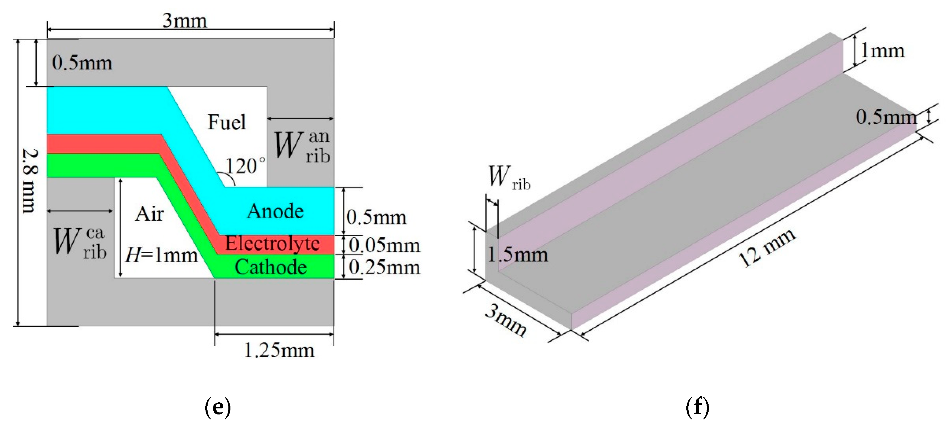
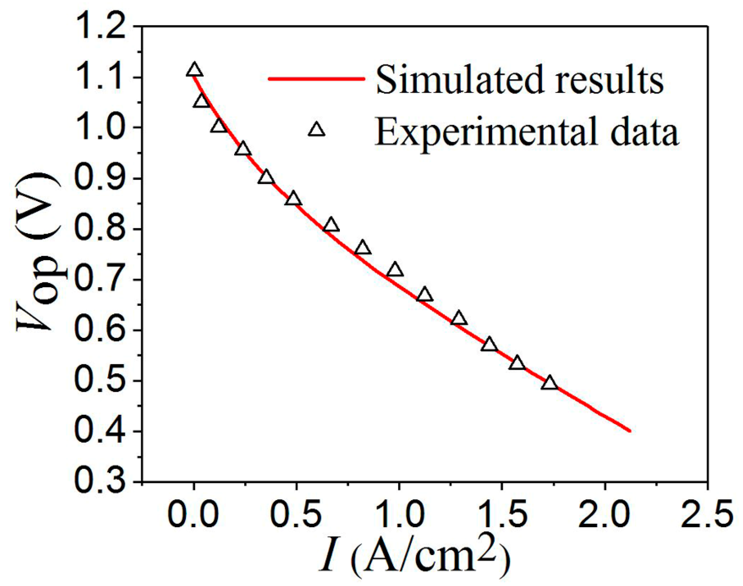
2. Model
3. Results and Discussion
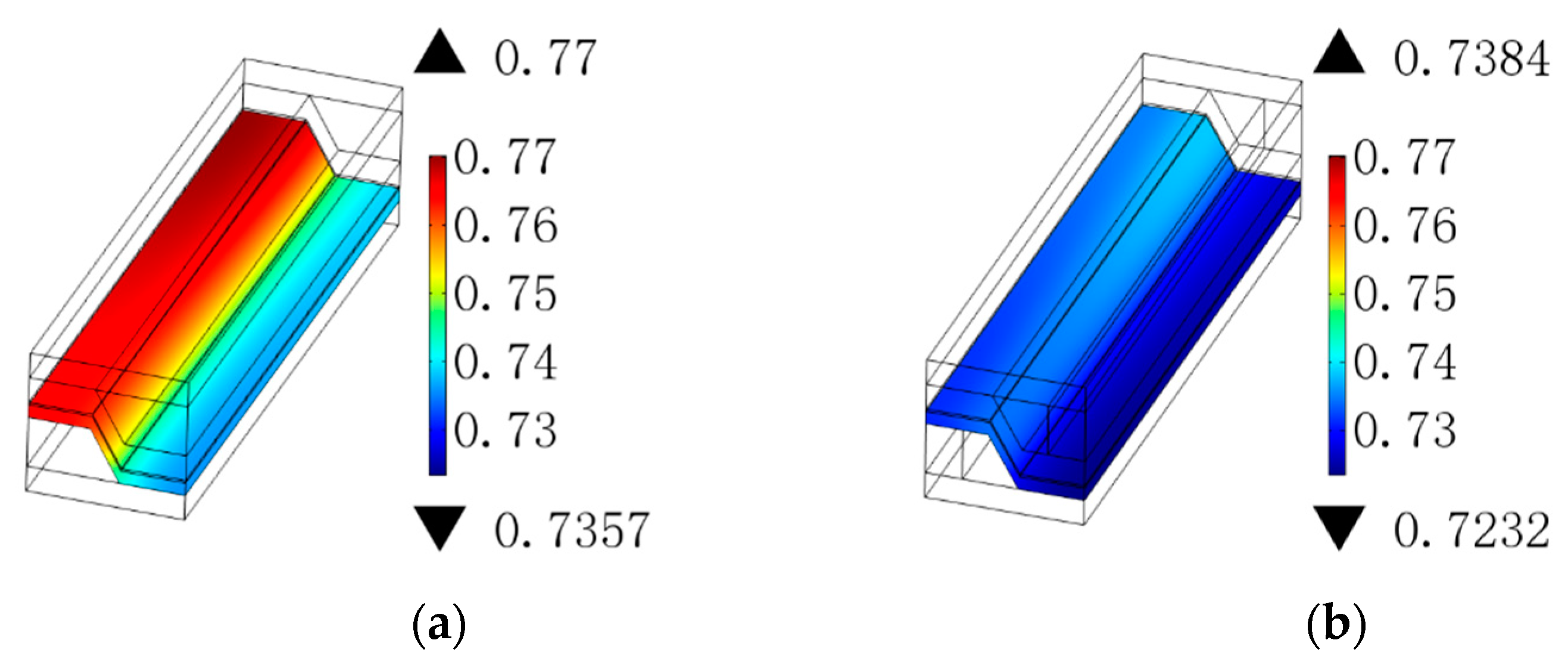
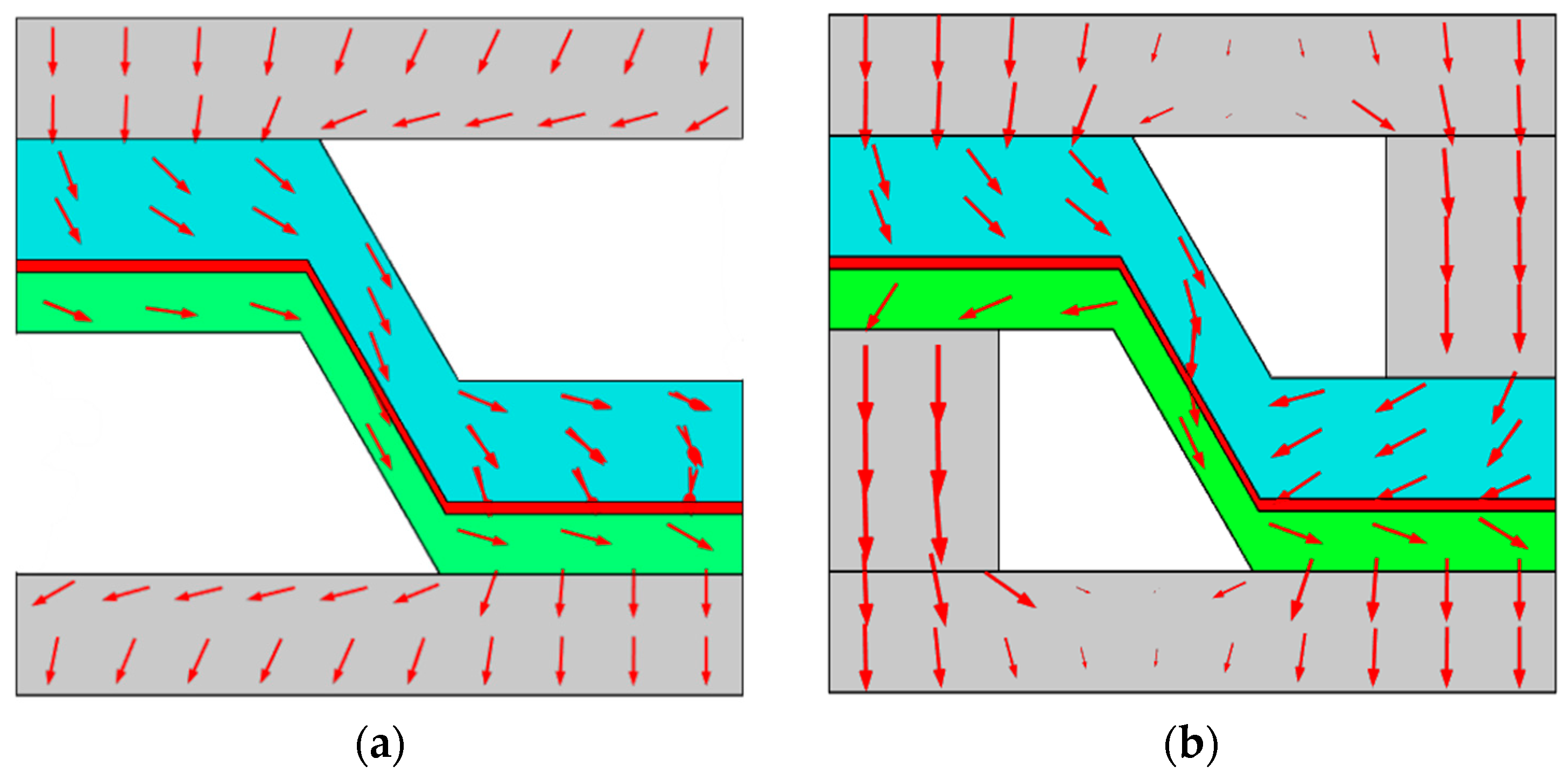
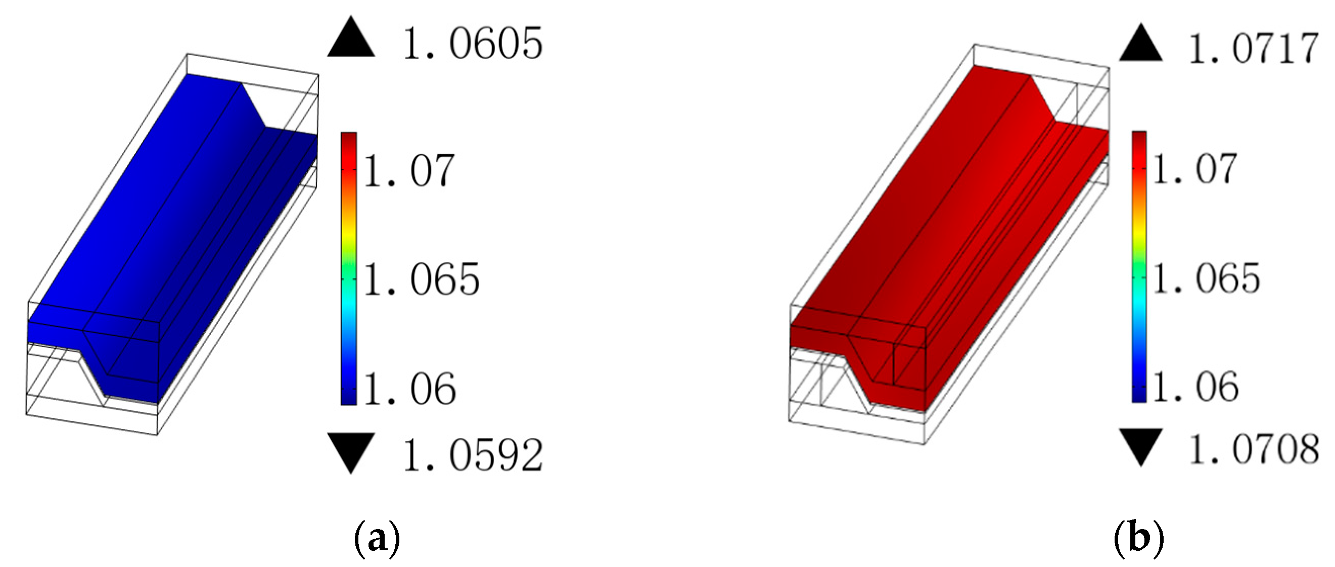
3.1. Ohmic Polarization
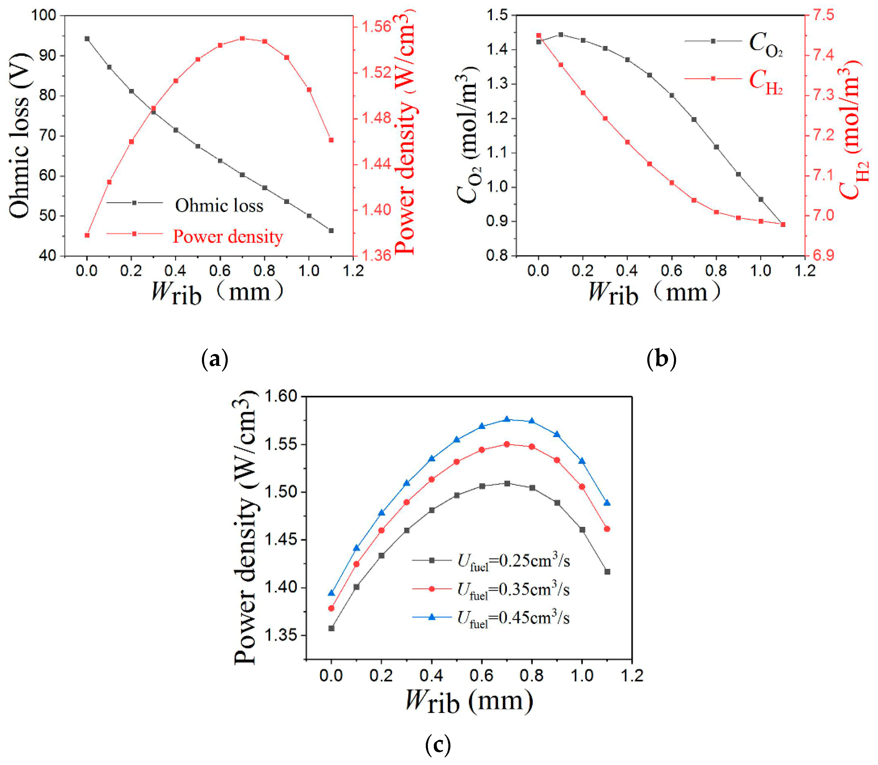
3.2. Gas Concentration Distribution
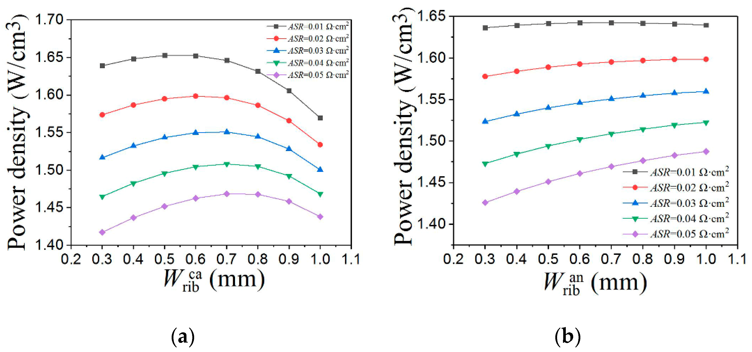
3.3. Vertical Rib Width
4. Conclusions
Author Contributions
Funding
Institutional Review Board Statement
Informed Consent Statement
Data Availability Statement
Conflicts of Interest
Nomenclature
| Contact resistance, (Ω cm2) | |
| Permeability coefficient, (m2) | |
| Molar concentration of species at channel inlet, (mol/m3) | |
| Molar concentration of species , (mol/m3) | |
| Specific heat capacity, (J/kg) | |
| Binary diffusion coefficient, (m2/s) | |
| Knudsen diffusion coefficient of species , (m2/s) | |
| Equivalent diffusion coefficient of species , (m2/s) | |
| Nernst potential, (V) | |
| Faraday constant, (96,487 C/mol) | |
| Electronic current density, (A/m2) | |
| Ionic current density, (A/m2) | |
| Local transfer current at anode, (A) | |
| Local transfer current at cathode, (A) | |
| Molecular mass, (kg/mol) | |
| Molar flux, (mol/m2/s) | |
| Universal gas constant, (J/mol/K) | |
| Total pressure, (Pa) | |
| One atmospheric pressure, (Pa) | |
| Species pressure at channel inlet, (Pa) | |
| Species pressure at TPB, (Pa) | |
| Pore radii, (m) | |
| Operating temperature, (K) | |
| Reference temperature, (K) | |
| Convection velocity, (m/s) | |
| Diffusion volume, (m3/mol) | |
| Molar fraction | |
| Local electronic potential, (V) | |
| Local ionic potential, (V) | |
| Operational potential, (V) | |
| Effective conductivity, (S/m) | |
| Anode activation polarization, (V) | |
| Cathode activation polarization, (V) | |
| The porosity | |
| Viscosity coefficient of fluid, (Pa·s) | |
| Density, (kg/m3) | |
| Tortuosity factor |
References
- Squizzato, E.; Sanna, C.; Glisenti, A.; Costamagna, P. Structural and Catalytic Characterization of La 0.6 Sr 0.4 MnO3 Nanofibers for Application in Direct Methane Intermediate Temperature Solid Oxide Fuel Cell Anodes. Energies 2021, 14, 3602. [Google Scholar] [CrossRef]
- Prokop, T.A.; Brus, G.; Szmyd, J.S. Microstructure Evolution in a Solid Oxide Fuel Cell Stack Quantified with Interfacial Free Energy. Energies 2021, 14, 3576. [Google Scholar] [CrossRef]
- Nenning, A.; Bischof, C.; Fleig, J.; Bram, M.; Opitz, A.K. The Relation of Microstructure, Materials Properties and Impedance of SOFC Electrodes: A Case Study of Ni/GDC Anodes. Energies 2020, 13, 987. [Google Scholar] [CrossRef] [Green Version]
- Fang, X.R.; Zhu, J.; Lin, Z.J. Effects of Electrode Composition and Thickness on the Mechanical Performance of a Solid Oxide Fuel Cell. Energies 2018, 11, 1735. [Google Scholar] [CrossRef] [Green Version]
- Mao, L.; Jackson, L.; Davies, B. Investigation of PEMFC fault diagnosis with consideration of sensor reliability. Int. J. Hydrog. Energy 2018, 43, 16941–16948. [Google Scholar] [CrossRef]
- He, K.; Zhang, C.; He, Q.B.; Wu, Q.; Jackson, L.; Mao, L. Effectiveness of PEMFC historical state and operating mode in PEMFC prognosis. Int. J. Hydrog. Energy 2020, 45, 32355–32366. [Google Scholar] [CrossRef]
- Chang, K.Y.; Lin, H.J.; Chen, P.C. The optimal performance estimation for an unknown PEMFC based on the Taguchi method and a generic numerical PEMFC model. Int. J. Hydrog. Energy 2009, 34, 1990–1998. [Google Scholar] [CrossRef]
- Kong, W.; Han, Z.; Lu, S.; Ni, M. A simple but effective design to enhance the performance and durability of direct carbon solid oxide fuel cells. Appl. Energy 2021, 287, 116586. [Google Scholar] [CrossRef]
- Zhu, J.; Lin, Z.J. Degradations of the electrochemical performance of solid oxide fuel cell induced by material microstructure evolutions. Appl. Energy 2018, 231, 22–28. [Google Scholar] [CrossRef]
- Kashmiri, S.A.; Tahir, M.W.; Afzal, U. Combustion Modeling and Simulation of Recycled Anode-off-Gas from Solid Oxide Fuel Cell. Energies 2020, 13, 5186. [Google Scholar] [CrossRef]
- Kong, W.; Zhang, W.; Huang, H.; Zhang, Y.; Wu, J.; Xu, Y. Analysis of micro-tubular SOFC stability under ambient and operating temperatures. J. Mater. Sci. Technol. 2018, 34, 1436–1440. [Google Scholar] [CrossRef]
- Huang, H.Y.; Han, Z.; Lu, S.Y.; Kong, W.; Wu, J.; Wang, X.R. The analysis of structure parameters of MOLB type solid oxide fuel cell. Int. J. Hydrog. Energy 2020, 45, 20351–20359. [Google Scholar] [CrossRef]
- Fu, Q.R.; Li, Z.Y.; Wei, W.; Liu, F.X.; Xu, X.F.; Liu, Z.J. Performance enhancement of a beam and slot interconnector for anode-supported SOFC stack. Energy Convers. Manag. 2021, 241, 114277. [Google Scholar] [CrossRef]
- Kong, W.; Han, Z.; Lu, S.Y.; Gao, X.; Wang, X.R. A novel interconnector design of SOFC. Int. J. Hydrog. Energy 2020, 45, 20329–20338. [Google Scholar] [CrossRef]
- Altan, T.; Celik, S. Effect of surface roughness of the metallic interconnects on the bonding strength in solid oxide fuel cells. Int. J. Hydrog. Energy 2020, 45, 35118–35129. [Google Scholar] [CrossRef]
- Hwang, J.; Chen, C.; Lai, D. Computational analysis of species transport and electrochemical characteristics of a MOLB-type SOFC. J. Power Sources 2005, 140, 235–242. [Google Scholar] [CrossRef]
- Yang, Y.; Wang, G.; Zhang, H.; Xia, W. Computational analysis of thermo-fluid and electrochemical characteristics of MOLB-type SOFC stacks. J. Power Sources 2007, 173, 233–239. [Google Scholar] [CrossRef]
- Yang, Y.; Wang, G.; Zhang, H.; Xia, W. Comparison of heat and mass transfer between planar and MOLB-type SOFCs. J. Power Sources 2008, 177, 426–433. [Google Scholar] [CrossRef]
- Sciacovelli, A.; Verda, V. Entropy Generation Minimization in a Tubular Solid Oxide Fuel Cell. J. Energy Resour. Technol. Trans. Asme 2010, 132, 012601. [Google Scholar] [CrossRef]
- Ramírez-Minguela, J.J.; Uribe-Ramírez, A.R.; Mendoza-Miranda, J.M.; Pérez-García, V.; Rodríguez-Muñoz, J.L.; Minchaca-Mojica, J.I.; Alfaro-Ayala, J.A. Study of the entropy generation in a SOFC for different operating conditions. Int. J. Hydrog. Energy 2016, 41, 8978–8991. [Google Scholar] [CrossRef]
- Ramírez-Minguela, J.J.; Mendoza-Miranda, J.M.; Muñoz-Carpio, V.D.; Rangel-Hernández, V.H.; Pérez-García, V.; Rodríguez-Muñoz, J.L. Internal reforming of methane in a mono-block-layer build solid oxide fuel cell with an embedding porous pipe: Numerical analysis. Energy Convers. Manag. 2014, 79, 461–469. [Google Scholar] [CrossRef]
- Stygar, M.; Brylewski, T.; Rękas, M. Effects of changes in MOLB-type SOFC cell geometry on temperature distribution and heat transfer rate in interconnects. Int. J. Heat Mass Transf. 2012, 55, 4421–4426. [Google Scholar] [CrossRef]
- Ramírez-Minguela, J.J.; Rodríguez-Muñoz, J.L.; Pérez-García, V.; Mendoza-Miranda, J.M.; Muñoz-Carpio, V.D.; Alfaro-Ayala, J.A. Solid oxide fuel cell numerical study: Modified MOLB-type and simple planar geometries with internal reforming. Electrochim. Acta 2015, 159, 149–157. [Google Scholar] [CrossRef]
- Barzi, Y.M.; Raoufi, A.; Lari, H. Performance analysis of a SOFC button cell using a CFD model. Int. J. Hydrog. Energy 2010, 35, 9468–9478. [Google Scholar] [CrossRef]
- Su, S.C.; Zhang, Q.; Gao, X.; Periasamy, V.; Kong, W. Effects of changes in solid oxide fuel cell electrode thickness on ohmic and concentration losss. Int. J. Hydrog. Energy 2016, 41, 16181–16190. [Google Scholar] [CrossRef] [Green Version]
- Sanyal, J.; Goldin, G.M.; Zhu, H.; Kee, R.J. A particle-based model for predicting the effective conductivities of composite electrodes. J. Power Sources 2010, 195, 6671–6679. [Google Scholar] [CrossRef]
- Liu, S.X.; Song, C.; Lin, Z.J. The effects of the interconnect rib contact resistance on the performance of planar solid oxide fuel cell stack and the rib design optimization. J. Power Sources 2008, 183, 214–225. [Google Scholar] [CrossRef]


| Equations | Regions | ||
|---|---|---|---|
| Momentum | Gas channel | (1) | |
| Electrode | (2) | ||
| Mass continuity equation | Gas channel Electrode | (3) | |
| Species | Gas channel | (4) | |
| Electrode | (5) | ||
| Charge | Electrode Interconnector | (6) | |
| Electrolyte | (7) |
| Boundary Setting | ||
|---|---|---|
| Air channel inlet | Species concentration | |
| Volume flow | ||
| Fuel channel inlet | Species concentration | |
| Volume flow | ||
| Air channel outlet | Outflow | |
| Pressure | ||
| Fuel channel outlet | Outflow | |
| Pressure | ||
| The cathode interconnector outer surface | Operational potential | |
| The anode interconnector outer surface | Nernst potential | |
| Anode/Electrolyte interface | The conversion current between the electron current and the ion current | |
| Inward flux | ; | |
| Cathode/Electrolyte interface | The conversion current between the electron current and the ion current | |
| Inward flux | ; N2: 0; | |
| Electrode/Interconnector interface | Contact resistance | |
| Parameters | Equations or Values |
|---|---|
| Binary diffusion coefficient | |
| Knudsen diffusion coefficient | |
| H2 equivalent diffusion coefficient | |
| H2O equivalent diffusion coefficient | |
| O2 equivalent diffusion coefficient | |
| N2 equivalent diffusion coefficient | |
| Anode conductivities | |
| Electrolyte conductivities | |
| Cathode conductivities | |
| Porosity | 0.3 cathode; 0.3 anode; |
| Curvature | 3.5 cathode 3.5 anode; |
| The diffusion volume (m3/mol) | 16.3 × 10⁻⁶ O2; 18.3 × 10⁻⁶ N2; 6.12 × 10⁻⁶ H2; 13.1 × 10⁻⁶ H2O; |
| Permeability (m2) | 1 × 10⁻¹³ m2 cathode; 1.7 × 10⁻¹⁰ m2 anode; |
| Viscosities (Pa s) | 4 × 10⁻⁵ air; 2.8 × 10⁻⁵ fuel; |
| T (K) | 1073.15 |
| (m) | 5 × 10⁻⁷ |
| 0.75, 0.5, 1, 0.5 | |
| (A m−2), (A m−2) | 860, 2000 |
| (J mol−1), (J mol−1) | 130 × 103, 120 × 103 |
| (V) | 0.7 |
| (Ω cm2) | 0.03 |
| Gas concentration at inlet (mol/m3) | 2.38 O2; 8.97 N2; 9.08 H2; 2.27 H2O; |
Publisher’s Note: MDPI stays neutral with regard to jurisdictional claims in published maps and institutional affiliations. |
© 2022 by the authors. Licensee MDPI, Basel, Switzerland. This article is an open access article distributed under the terms and conditions of the Creative Commons Attribution (CC BY) license (https://creativecommons.org/licenses/by/4.0/).
Share and Cite
Lu, S.; Zhang, M.; Wu, J.; Kong, W. Performance Investigation on Mono-Block-Layer Build Type Solid Oxide Fuel Cells with a Vertical Rib Design. Energies 2022, 15, 979. https://doi.org/10.3390/en15030979
Lu S, Zhang M, Wu J, Kong W. Performance Investigation on Mono-Block-Layer Build Type Solid Oxide Fuel Cells with a Vertical Rib Design. Energies. 2022; 15(3):979. https://doi.org/10.3390/en15030979
Chicago/Turabian StyleLu, Siyu, Man Zhang, Jie Wu, and Wei Kong. 2022. "Performance Investigation on Mono-Block-Layer Build Type Solid Oxide Fuel Cells with a Vertical Rib Design" Energies 15, no. 3: 979. https://doi.org/10.3390/en15030979
APA StyleLu, S., Zhang, M., Wu, J., & Kong, W. (2022). Performance Investigation on Mono-Block-Layer Build Type Solid Oxide Fuel Cells with a Vertical Rib Design. Energies, 15(3), 979. https://doi.org/10.3390/en15030979