
Hydrate-Based Separation for Industrial Gas Mixtures

Abstract
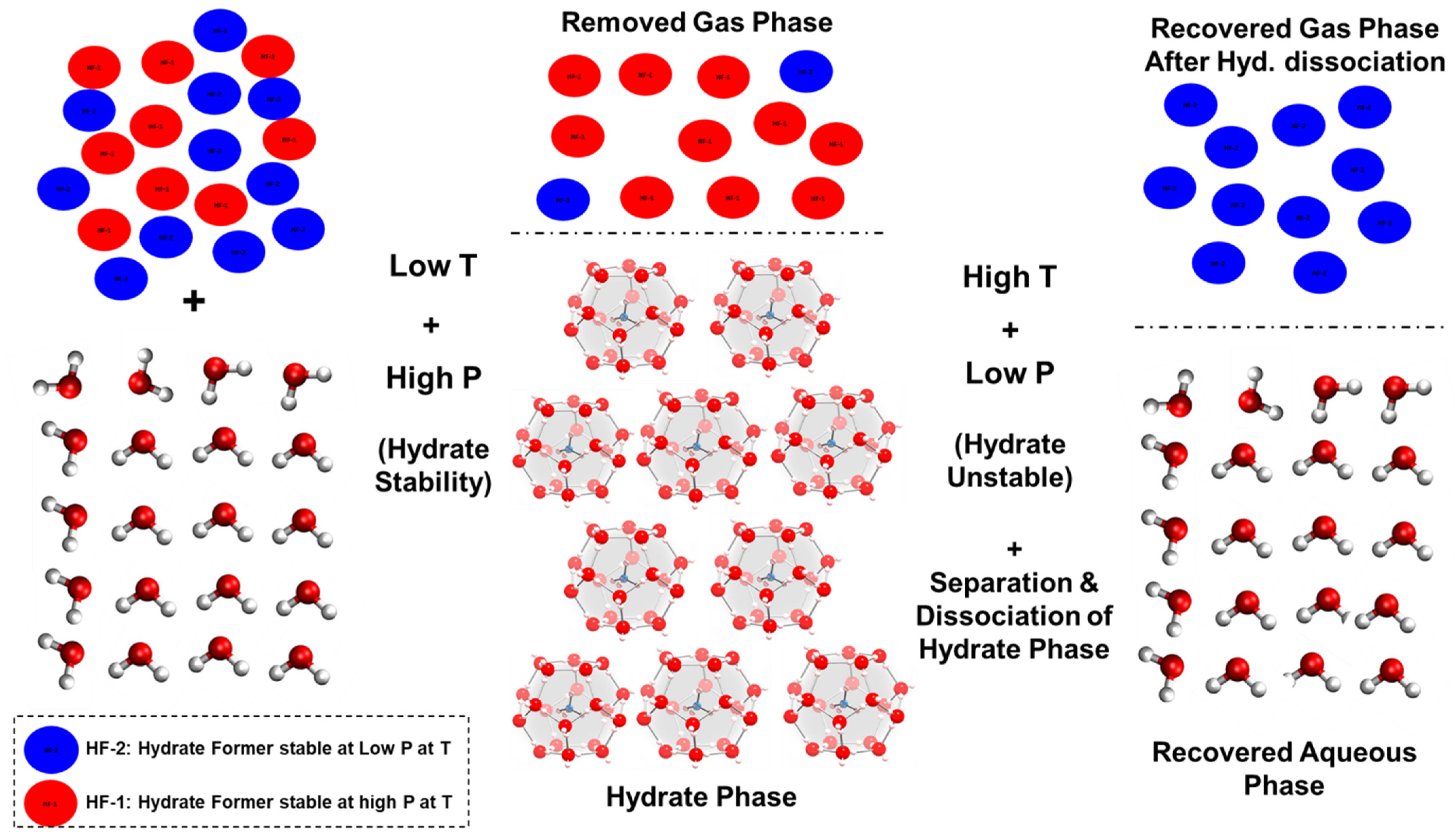
1. Introduction
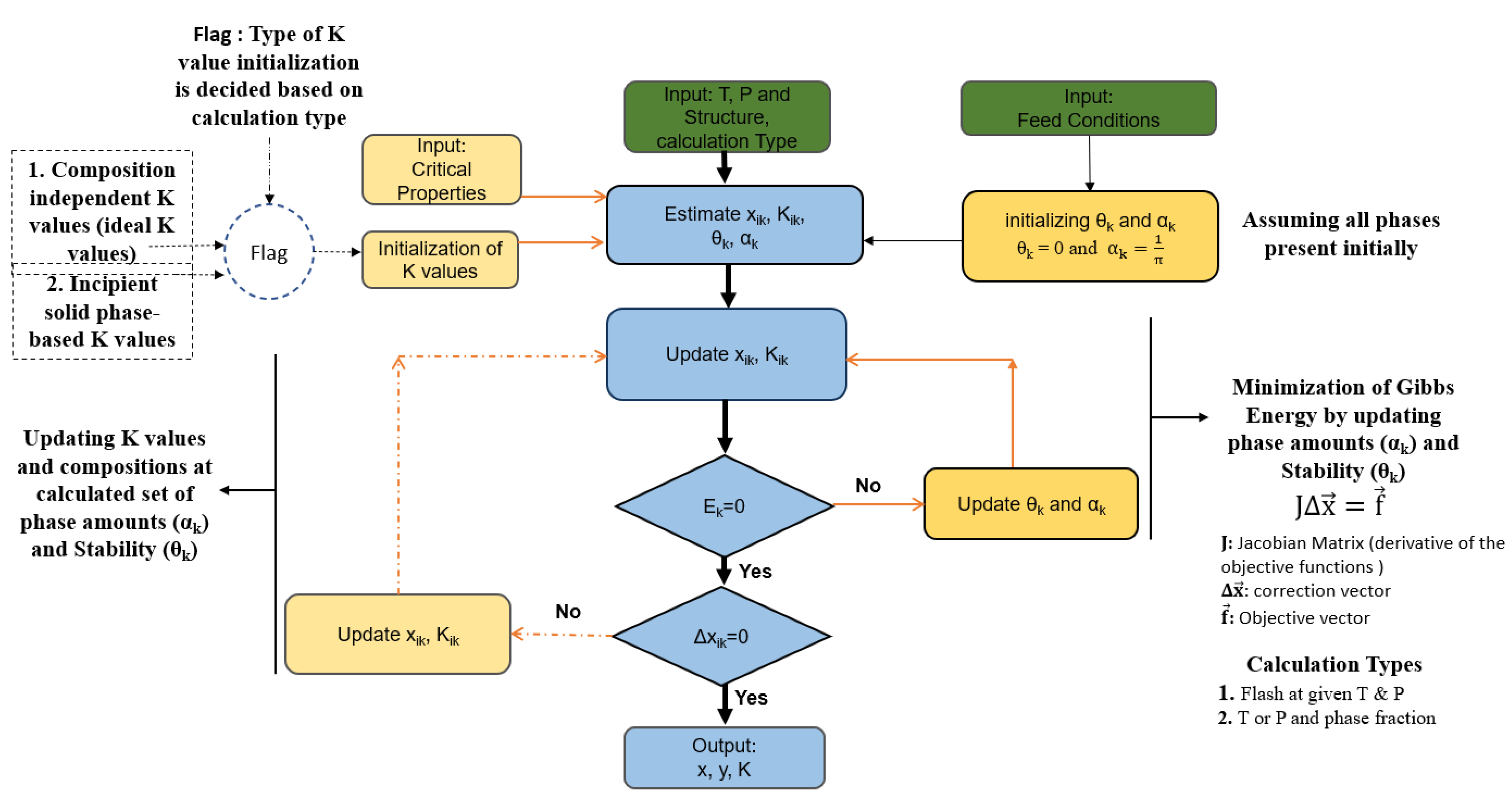
2. Theory
- fugacity of water in any phase k
- fugacity of water at standard conditions (To = 298.15 K and P = 1 bar)
- chemical potential of water in any phase k
- Gibbs free energy of water at standard conditions (To = 298.15 K and P = 1 bar)
- Gas constant.
3. Results and Discussions
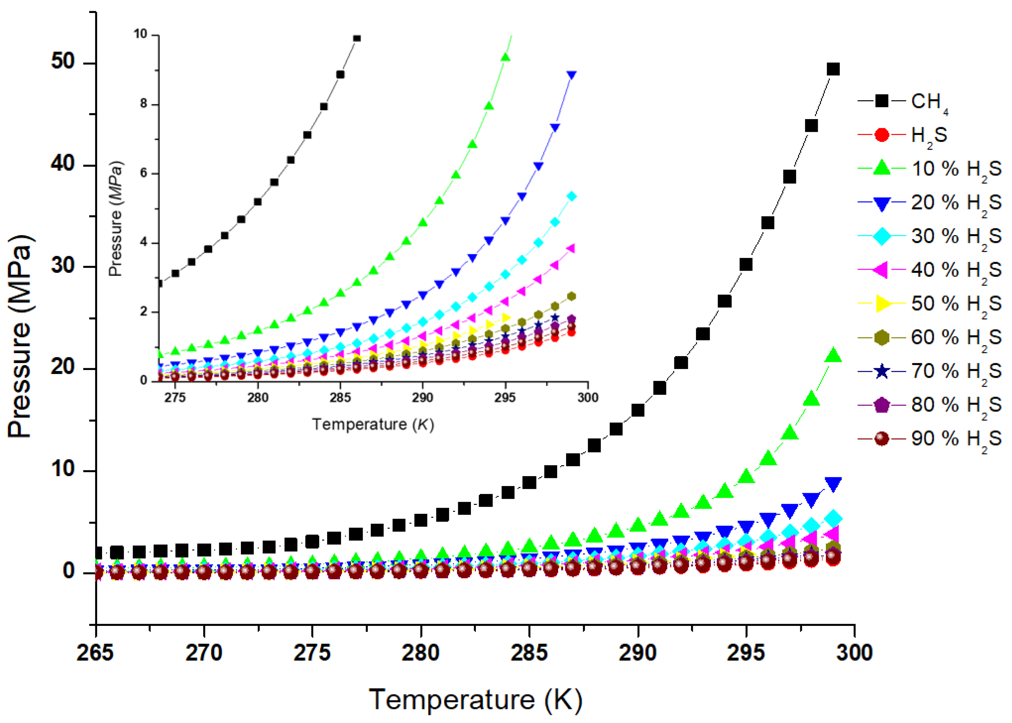
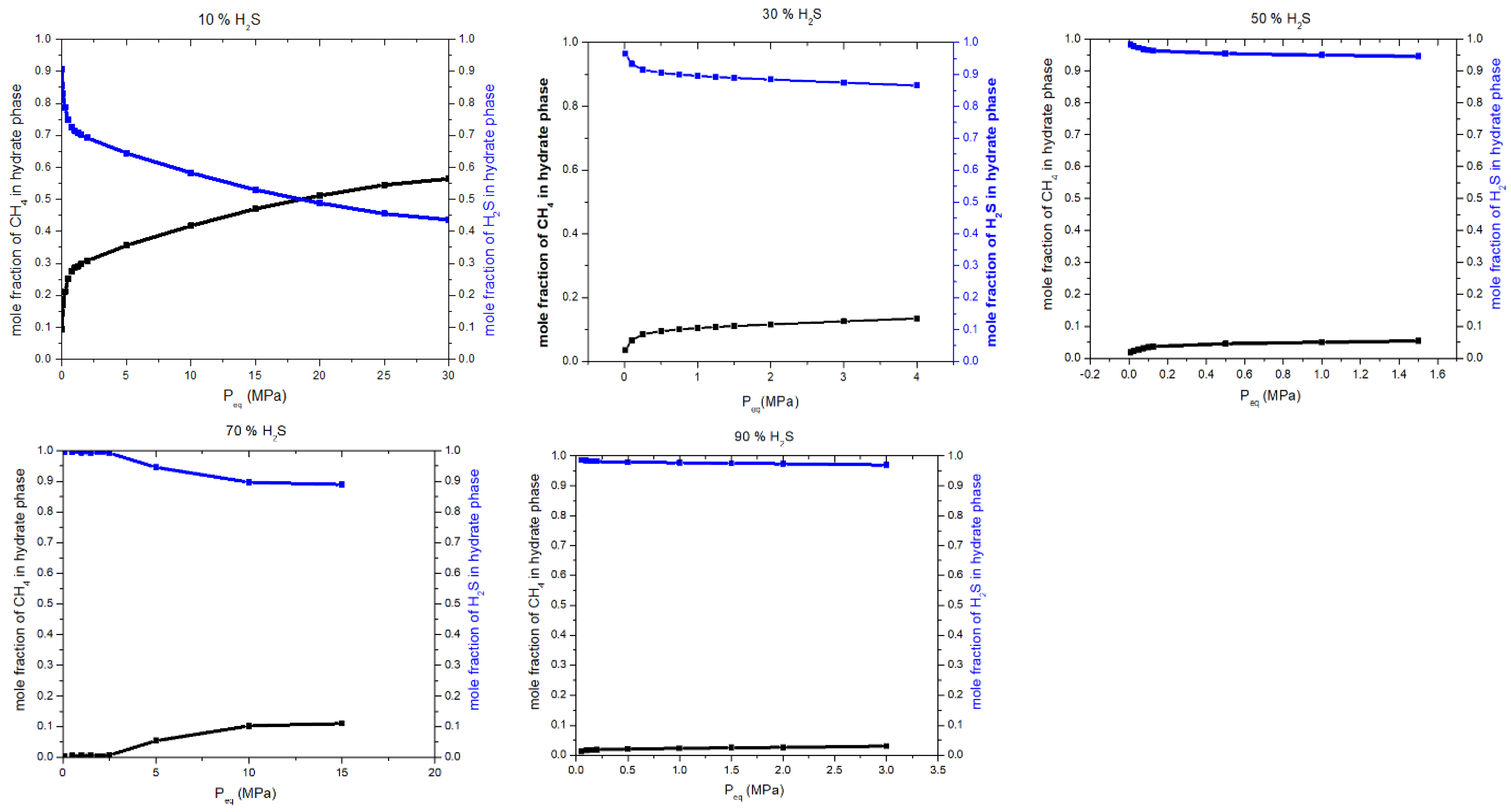
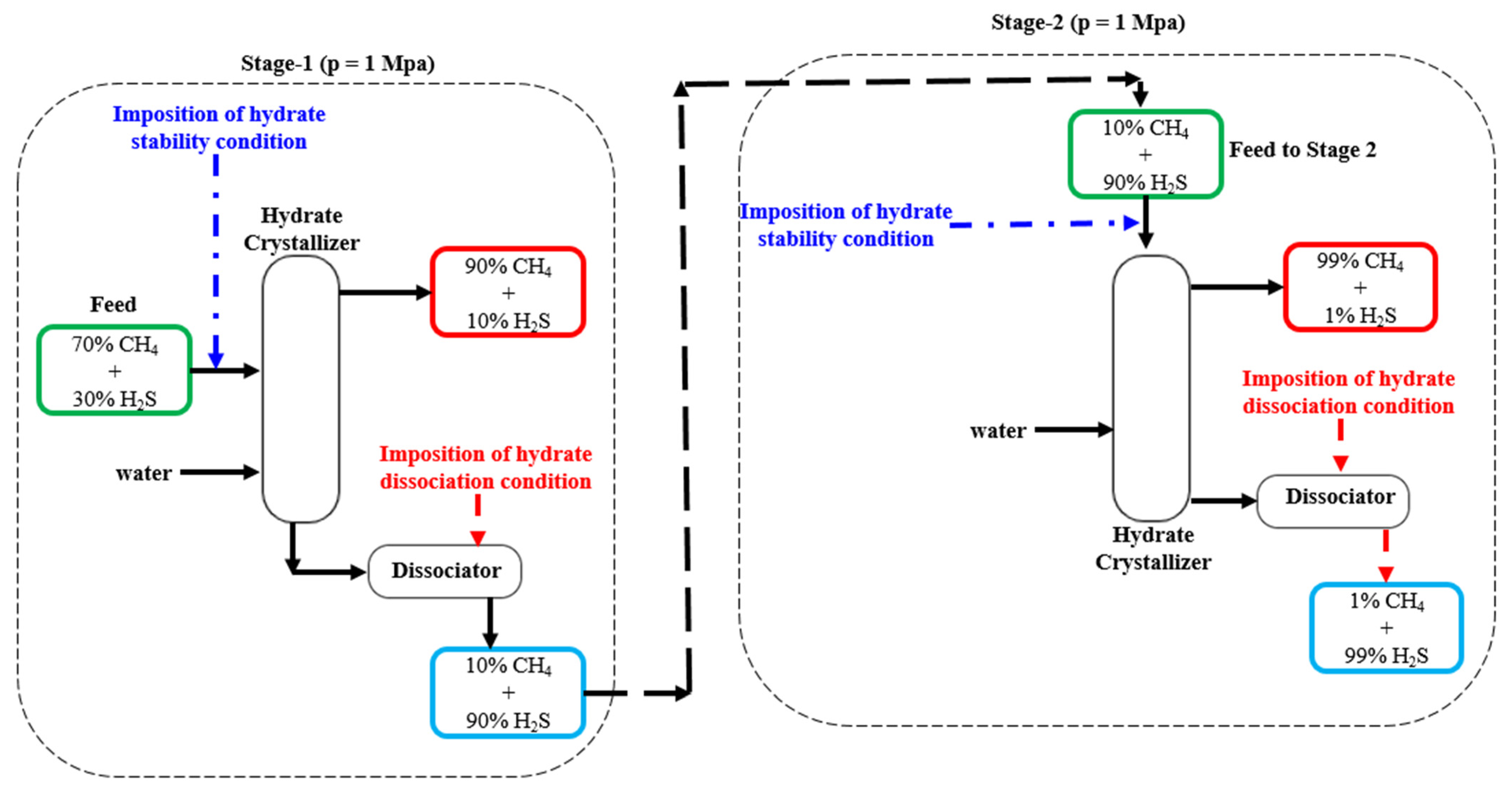
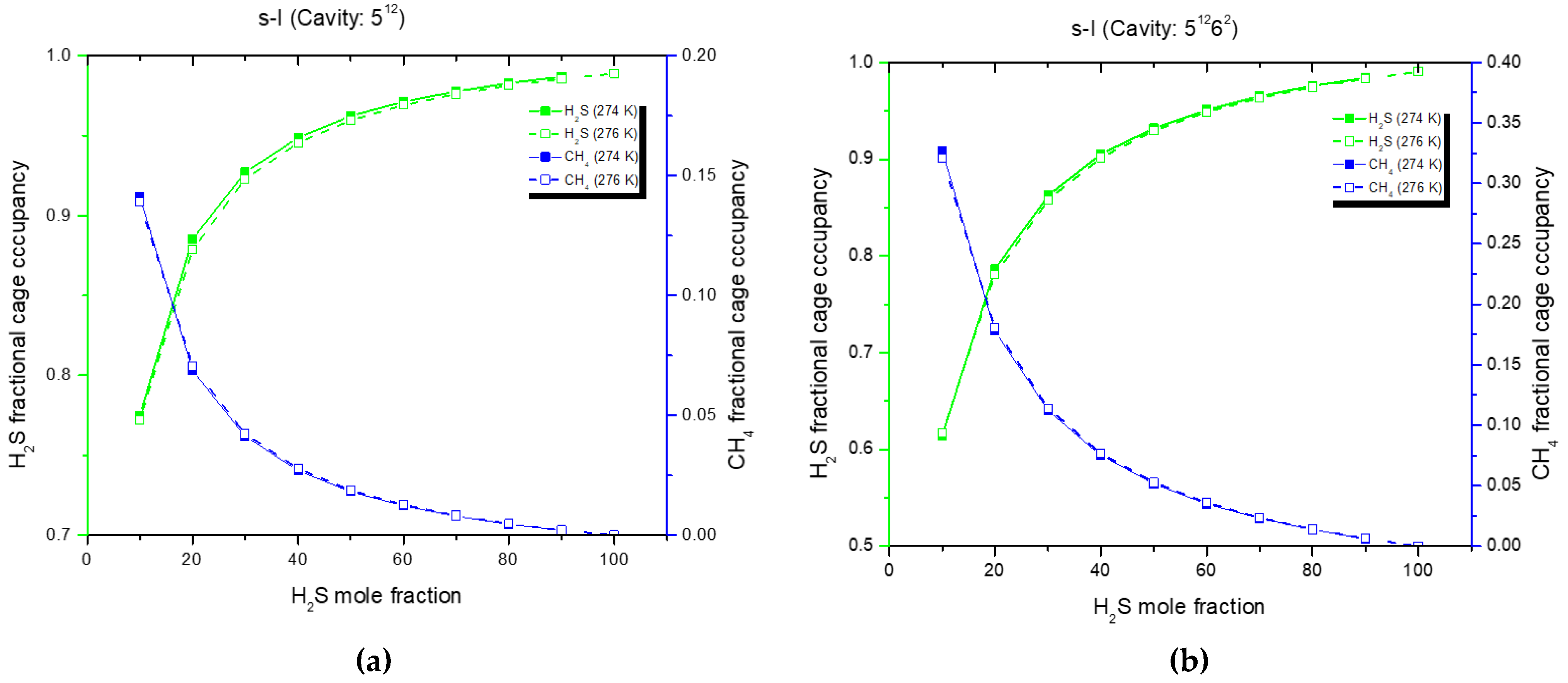
3.1. Process Design for CH4 + H2S Mixture
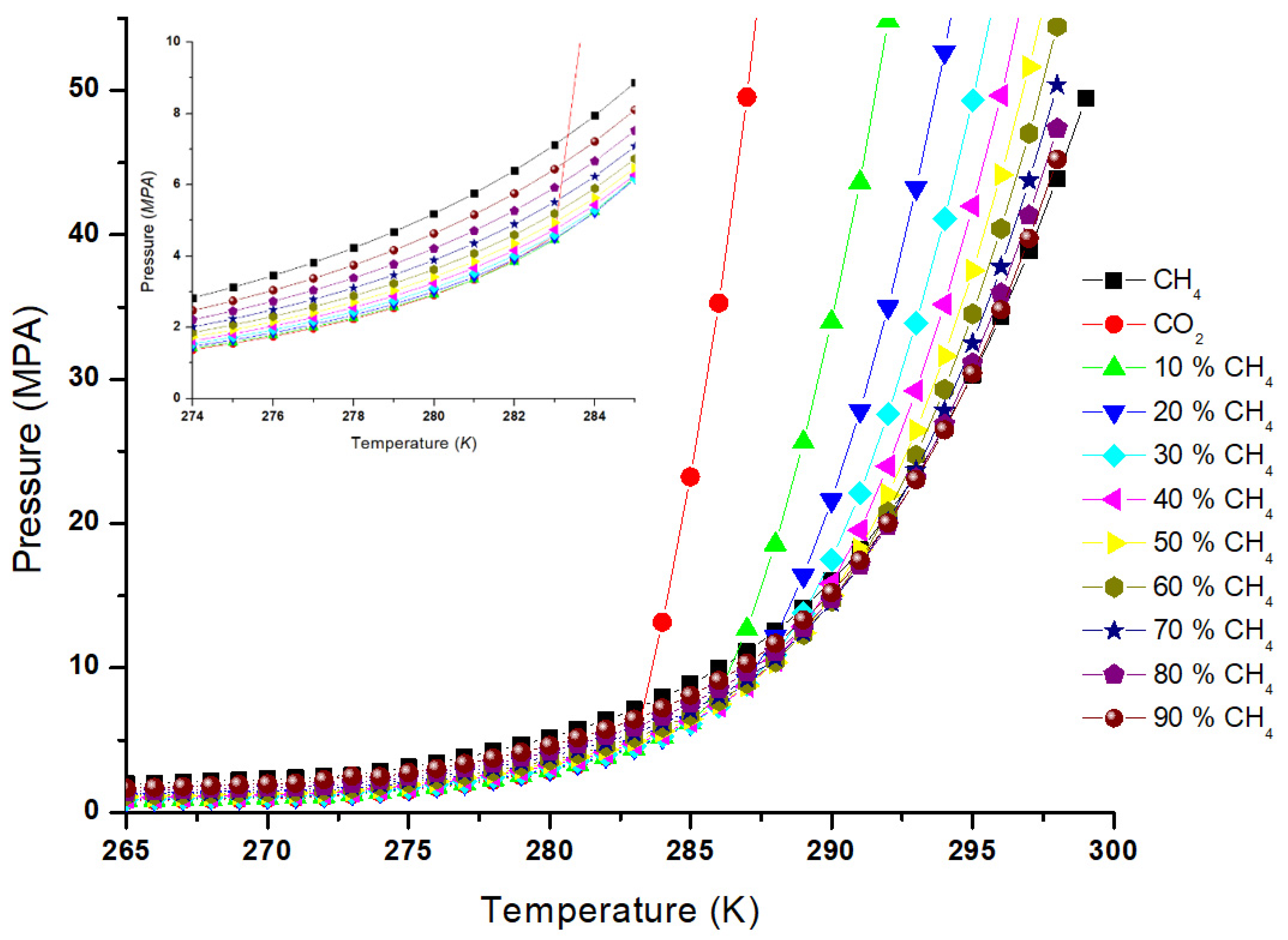
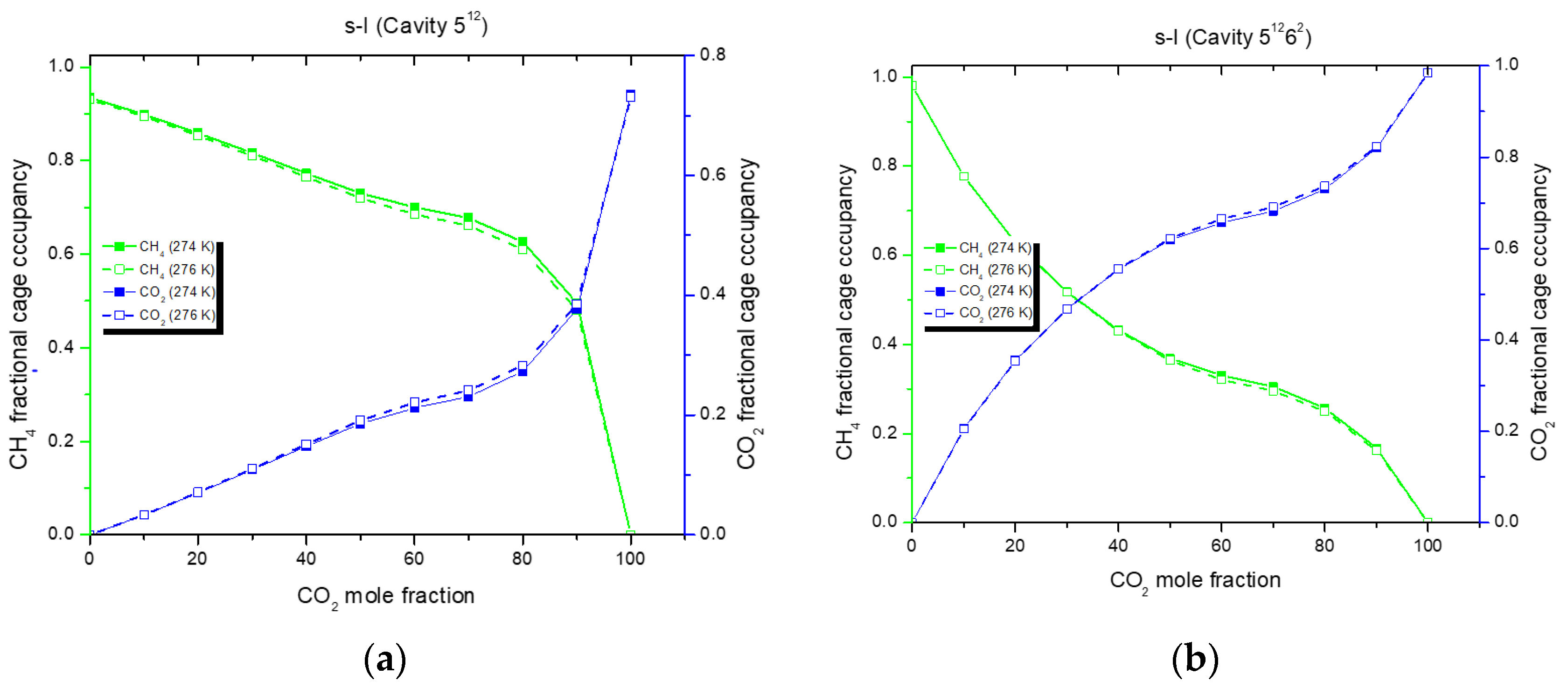
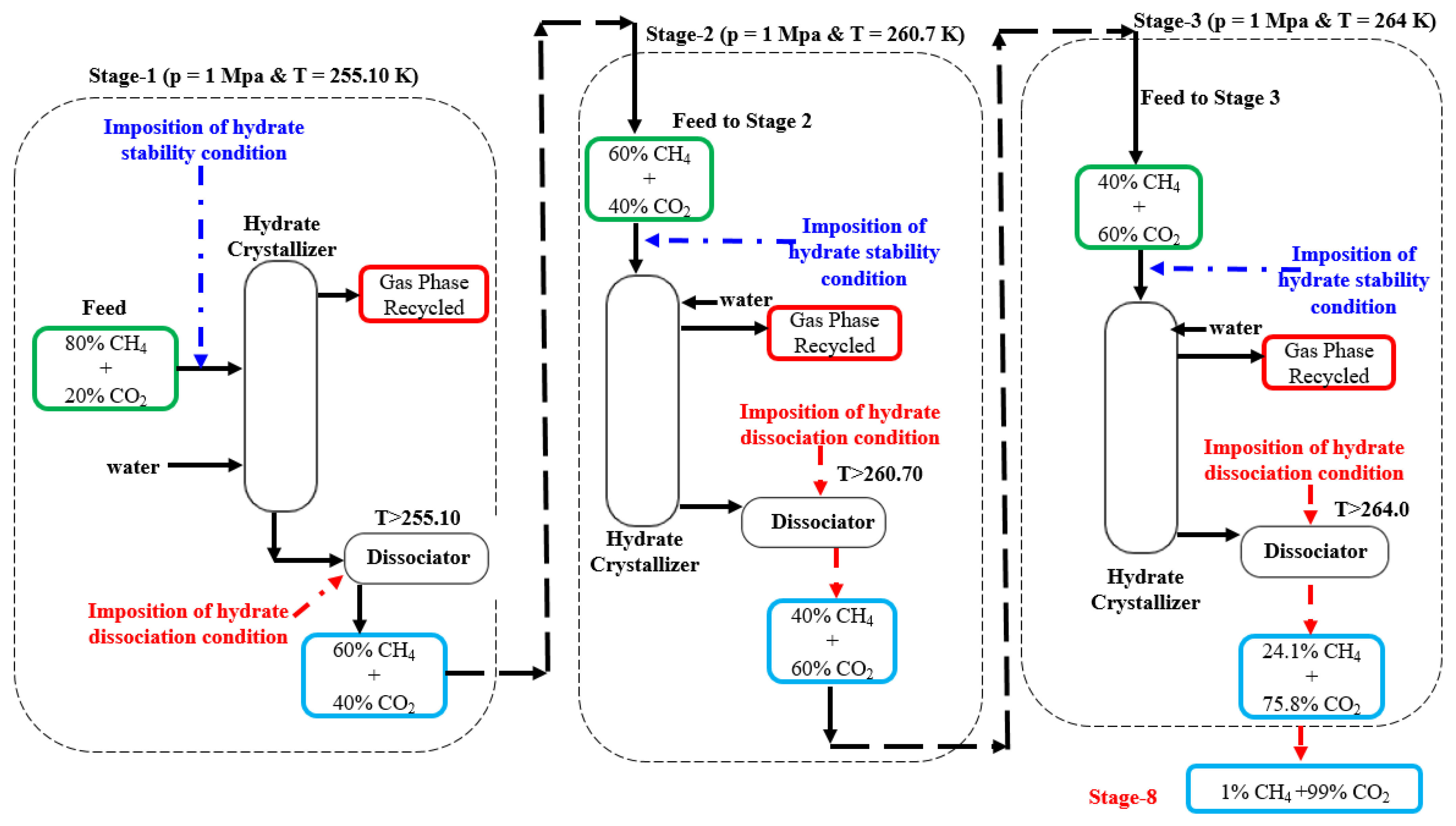
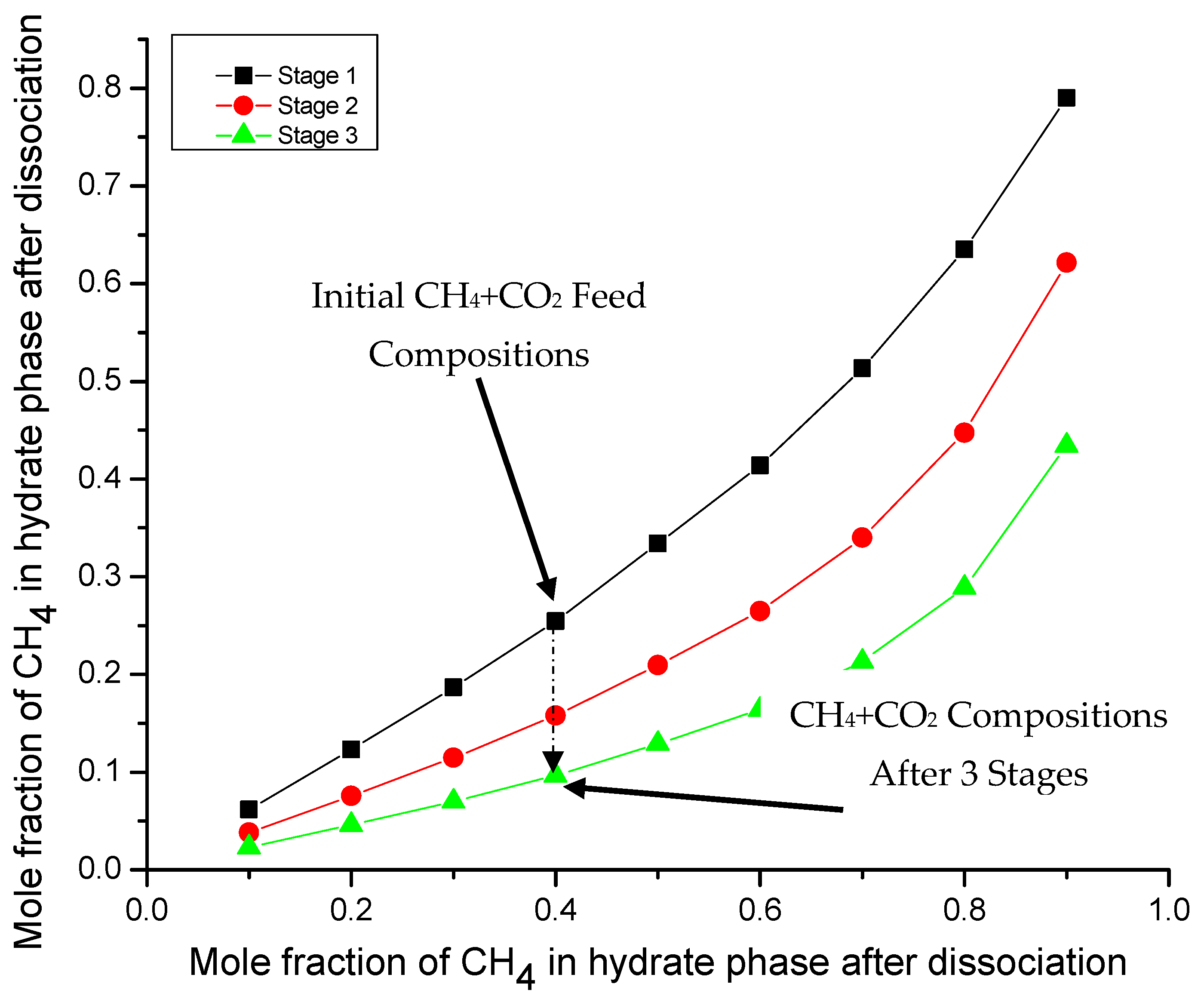
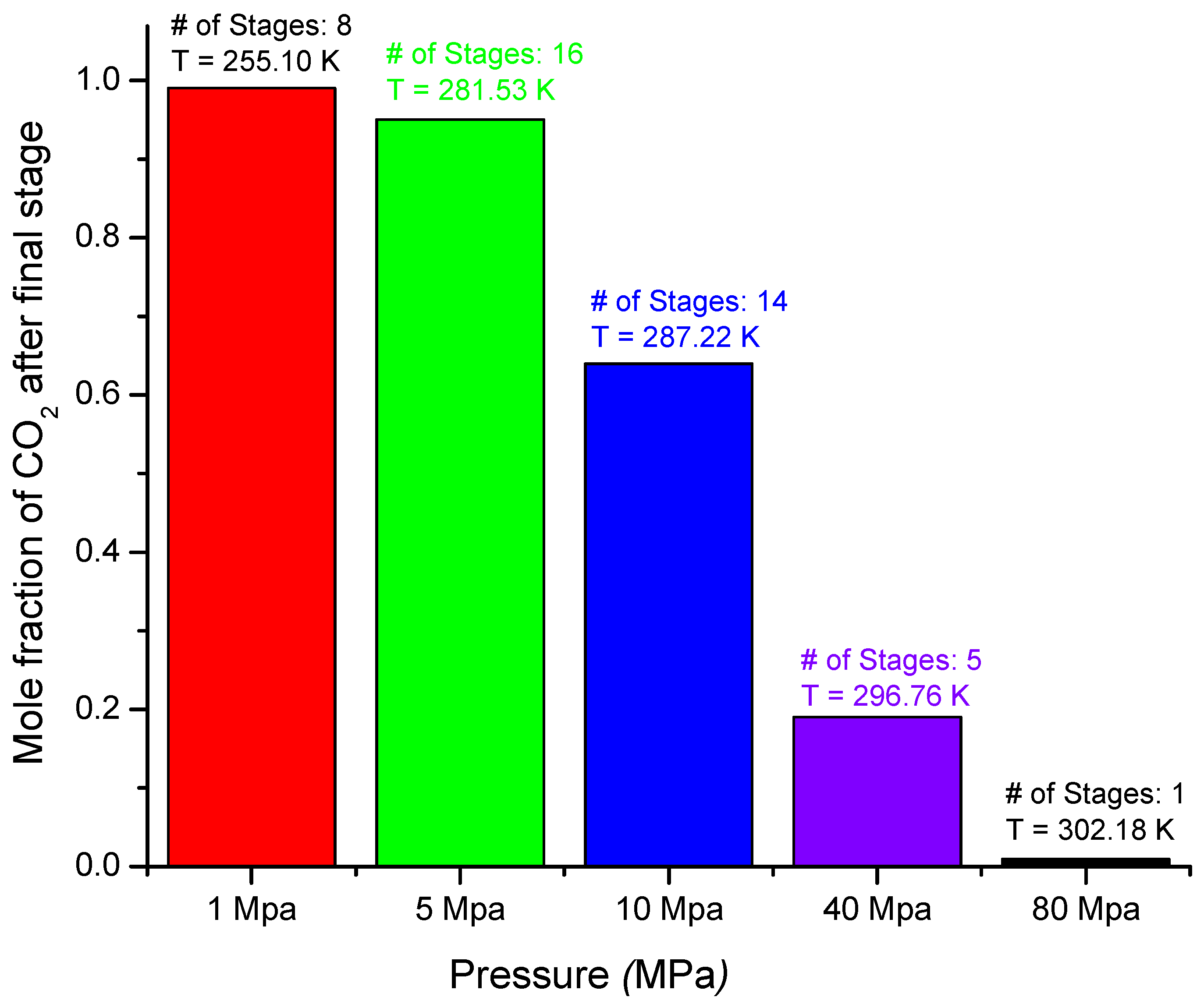
3.2. Process Design for CH4 + CO2 Mixture

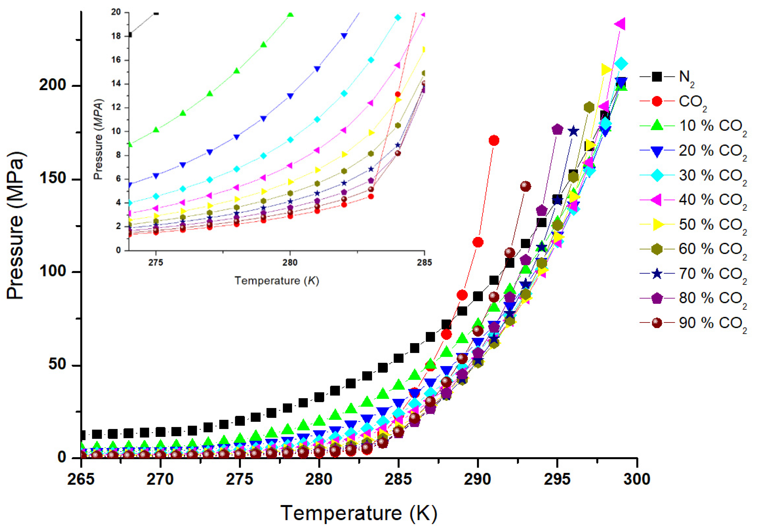
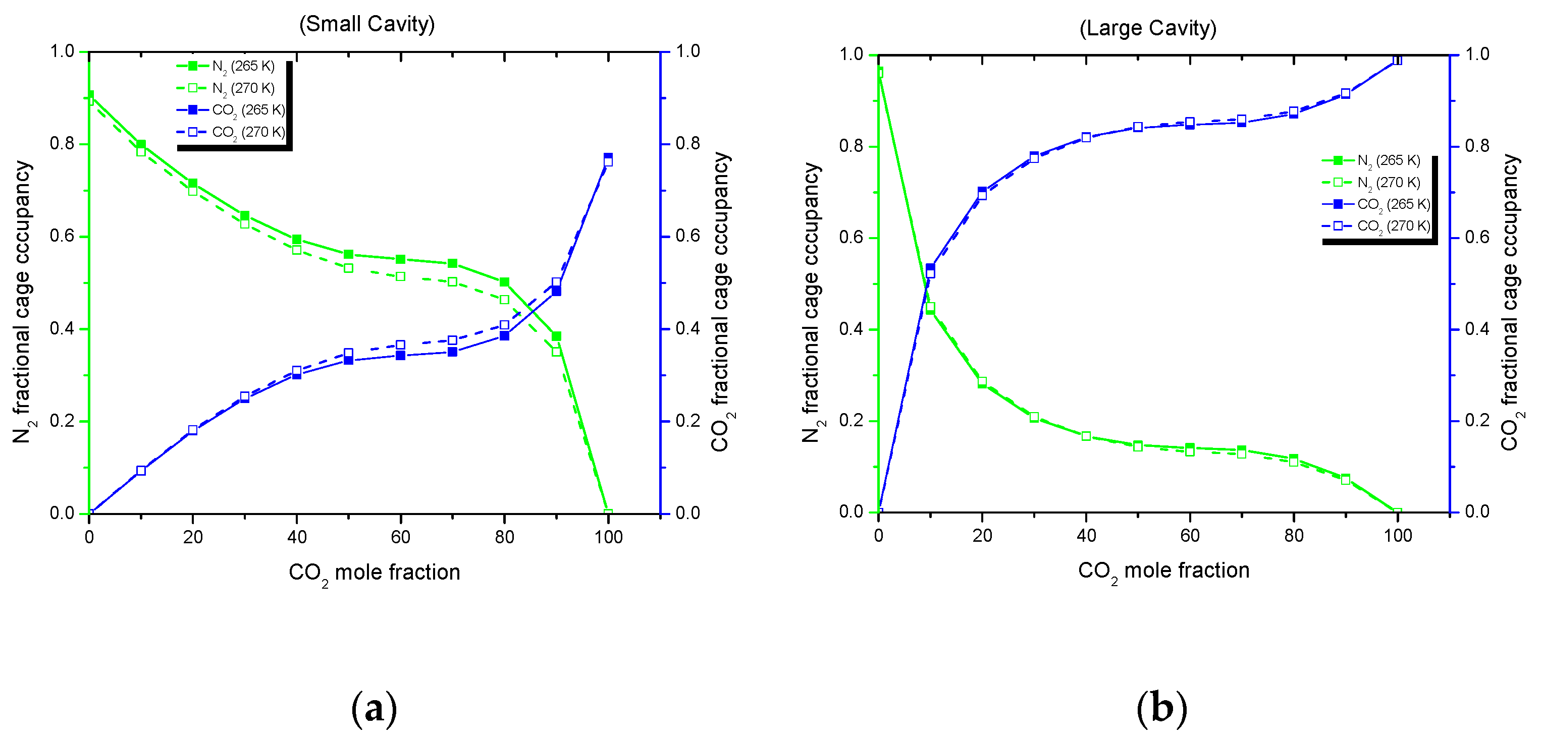
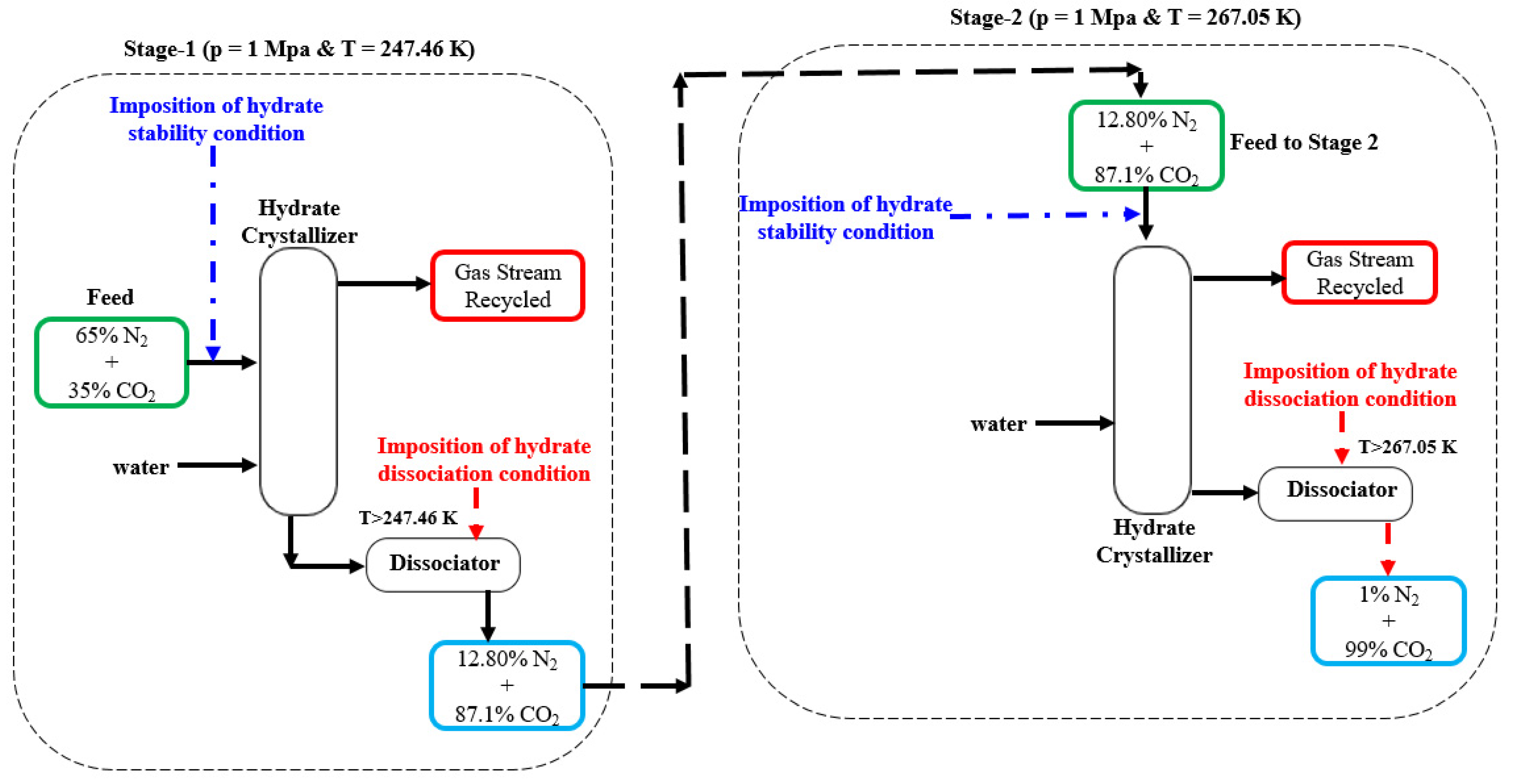
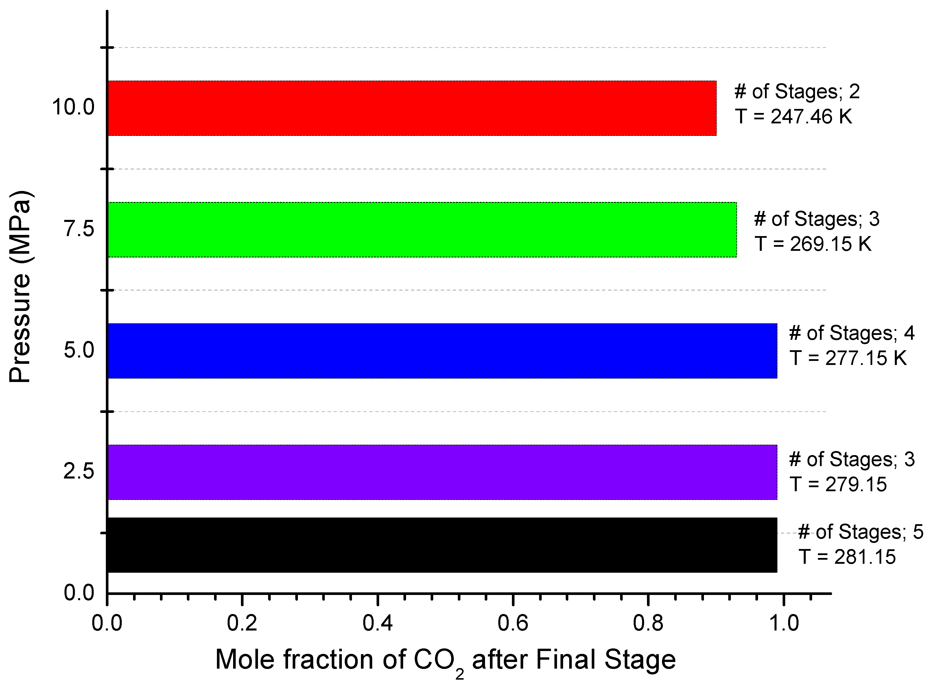
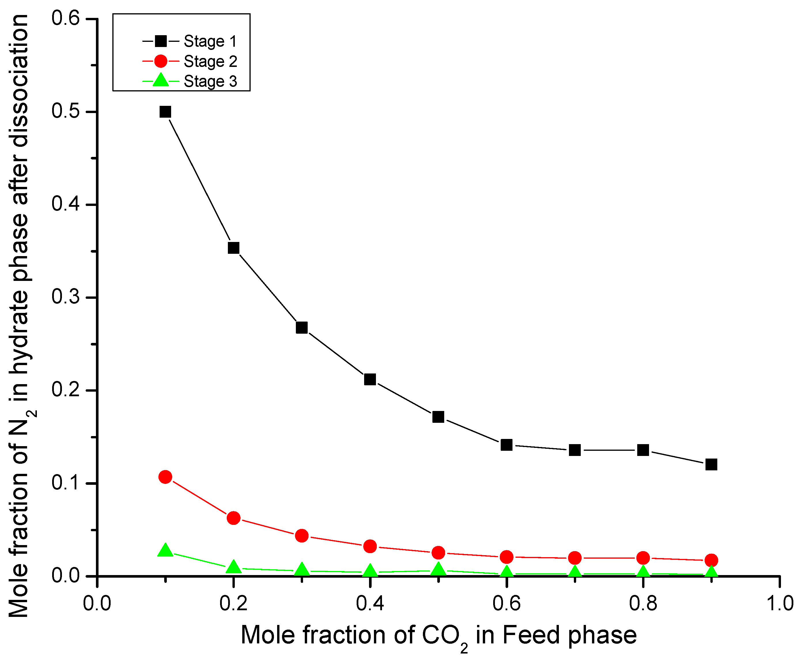
3.3. Process Design for N2 + CO2 Mixture
3.4. Ternary Gas Mixture
4. Conclusions
Supplementary Materials
Author Contributions
Funding
Institutional Review Board Statement
Informed Consent Statement
Data Availability Statement
Acknowledgments
Conflicts of Interest
References
- Linga, P.; Kumar, R.; Lee, J.D.; Ripmeester, J.; Englezos, P. A new apparatus to enhance the rate of gas hydrate formation: Application to capture of carbon dioxide. Int. J. Greenh. Gas Control 2010, 4, 630–637. [Google Scholar] [CrossRef]
- Matsuda, S.; Tsuda, H.; Mori, Y.H. Hydrate formation using water spraying onto a cooled solid surface in a guest gas. AIChE J. 2006, 52, 2978–2987. [Google Scholar] [CrossRef]
- Chatti, I.; Delahaye, A.; Fournaison, L.; Petitet, J.P. Benefits and drawbacks of clathrate hydrates: A review of their areas of interest. Energy Convers. Manag. 2005, 46, 1333–1343. [Google Scholar] [CrossRef]
- Gudmundsson, J.S.; Andersson, V.; Levik, O.I.; Mork, M. Hydrate Technology for Capturing Stranded Gas. Ann. N. Y. Acad. Sci. 2000, 912, 403–410. [Google Scholar] [CrossRef]
- Englezos, P. Clathrate hydrates. Ind. Eng. Chem. Res. 2002, 32, 1251–1274. [Google Scholar] [CrossRef]
- Makogon, I. Hydrates of Natural Gas; PennwWell Books: Tulsa, OK, USA, 1981. [Google Scholar]
- Thomas, S.; Dawe, R.A. Review of ways to transport natural gas energy from countries which do not need the gas for domestic use. Energy 2003, 28, 1461–1477. [Google Scholar] [CrossRef]
- Adeyemo, A.; Kumar, R.; Linga, P.; Ripmeester, J.; Englezos, P. Capture of carbon dioxide from flue or fuel gas mixtures by clathrate crystallization in a silica gel column. Int. J. Greenh. Gas Control 2010, 4, 478–485. [Google Scholar] [CrossRef]
- Khan, M. Phase Equilibria Modeling of Inhibited Gas Hydrate Systems Including Salts: Applications in Flow Assurance, Seawater Desalination and Gas Separation; Colorado School of Mines: Golden, CO, USA, 2016. [Google Scholar]
- Trautz, R.; Swisher, J.; Chiaramonte, L.; Hollis, R.; Perron, J.; Pronske, K.; Myhre, R.; Stone, M.; Saini, D.; Jordan, P.; et al. California CO2 Storage Assurance Facility Enterprise (C2SAFE): Final Technical Report; Pittsburgh, PA, USA; Morganrown, WV, USA, 2018. [Google Scholar] [CrossRef]
- Bergerson, J.A.; Lave, L.B. Baseload coal investment decisions under uncertain carbon legislation. Environ. Sci. Technol. 2007, 41, 3431–3436. [Google Scholar] [CrossRef] [PubMed][Green Version]
- U.S. Energy Administration, Office of Integratedand International Energy Analysis. Annual Energy Outlook 2013 with Projections to 2040; 2013. [CrossRef]
- Carbon Capture and Storage: An Effective Way to Mitigate Global Warming on JSTOR. Available online: https://www.jstor.org/stable/24098511 (accessed on 29 September 2021).
- Abbasi, T.; Tauseef, S.M.; Abbasi, S.A. Anaerobic digestion for global warming control and energy generation—An overview. Renew. Sustain. Energy Rev. 2012, 16, 3228–3242. [Google Scholar] [CrossRef]
- Yu, C.-H.; Huang, C.-H.; Tan, C.-S. A Review of CO2 Capture by Absorption and Adsorption. Aerosol Air Qual. Res. 2012, 12, 745–769. [Google Scholar] [CrossRef]
- Lott, D.E. Improvements in noble gas separation methodology: A nude cryogenic trap. Geochem. Geophys. Geosystems 2001, 2, 2001GC000202. [Google Scholar] [CrossRef]
- Bernardo, P.; Drioli, E.; Golemme, G. Membrane Gas Separation: A Review/State of the Art. Ind. Eng. Chem. Res. 2009, 48, 4638–4663. [Google Scholar] [CrossRef]
- Kang, S.-P.; Lee, H.L. Recovery of CO2 from Flue Gas Using Gas Hydrate: Thermodynamic Verification through Phase Equilibrium Measurements. Environ. Sci. Technol. 2000, 34, 4397–4400. [Google Scholar] [CrossRef]
- Aaron, D. Separation of CO2 from Flue Gas: A Review. Taylor Fr. 2005, 40, 321–348. [Google Scholar] [CrossRef]
- Klara, S.M.; Srivastava, R.D. U.S. DOE integrated collaborative technology development program for CO2 separation and capture. Environ. Prog. 2002, 21, 247–253. [Google Scholar] [CrossRef]
- Linga, P.; Kumar, R.; Englezos, P. Gas hydrate formation from hydrogen/carbon dioxide and nitrogen/carbon dioxide gas mixtures. Chem. Eng. Sci. 2007, 62, 4268–4276. [Google Scholar] [CrossRef]
- Linga, P.; Kumar, R.; Englezos, P. The clathrate hydrate process for post and pre-combustion capture of carbon dioxide. J. Hazard. Mater. 2007, 149, 625–629. [Google Scholar] [CrossRef]
- Linga, P. Separation of Carbon Dioxide from Flue Gas (Post-Combustion Capture) via Gas Hydrate Crystallization. Ph.D. Thesis, University of British Columbia, Vancouver, BC, Canada, 2009. [Google Scholar] [CrossRef]
- Azari, A.; Atashrouz, S.; Mirshekar, H.; González, A.; Okumura, K.; Ten Elshof, J.E. Prediction the Vapor-Liquid Equilibria of CO2-Containing Binary Refrigerant Mixtures Using Artificial Neural Networks. ISRN Chem. Eng. 2013, 2013, 930484. [Google Scholar] [CrossRef]
- Platteeuw, J.C.; van der Waals, J.H. Thermodynamic properties of gas hydrates. Mol. Phys. 1958, 1, 91–96. [Google Scholar] [CrossRef]
- Ward, Z.T. Phase Equilibria of Gas Hydrates Containing Hydrogen Sulfide and Carbon Dioxide; Colorado School of Mines: Golden, CO, USA, 2015. [Google Scholar]
- Khan, M.N.; Warrier, P.; Peters, C.J.; Koh, C.A. Advancements in hydrate phase equilibria and modeling of gas hydrates systems. Fluid Phase Equilib. 2018, 463, 48–61. [Google Scholar] [CrossRef]
- Khan, M.N.; Warrier, P.; Creek, J.L.; Peters, C.J.; Koh, C.A. Vapour-liquid equilibria (VLE) and gas hydrate phase equilibria predictions using the cubic-plus association equation of state: CSMGem extension to association EoS model. J. Nat. Gas Sci. Eng. 2021, 94, 104083. [Google Scholar] [CrossRef]
- Shock, E.L.; Helgeson, H.C. Calculation of the thermodynamic and transport properties of aqueous species at high pressures and temperatures: Standard partial molal properties of organic species. Geochim. Cosmochim. Acta 1990, 54, 915–945. [Google Scholar] [CrossRef]
- Ballard, A.L. Non-Ideal Hydrate Solid Solution Model for a Multi-Phase Equilibria Program, A. Doctoral Dissertation, Colorado School of Mines, Golden, CO, USA, 2002. [Google Scholar]
- Sloan, E.D., Jr.; Koh, C.A. Clathrate Hydrates of Natural Gases; CRC Press: Golden, CO, USA, 2007. [Google Scholar]
- Ballard, A.L.; Sloan, E.D. The next generation of hydrate prediction: Part III. Gibbs energy minimization formalism. Fluid Phase Equilib. 2004, 218, 15–31. [Google Scholar] [CrossRef]
- Jager, M.D.; Ballard, A.L.; Sloan, E.D. The next generation of hydrate prediction: II. Dedicated aqueous phase fugacity model for hydrate prediction. Fluid Phase Equilib. 2003, 211, 85–107. [Google Scholar] [CrossRef]
- Ballard, A.L.; Sloan, J.D. The Next Generation of Hydrate Prediction: An Overview. J. Supramol. Chem. 2002, 2, 385–392. [Google Scholar] [CrossRef]
- Partoon, B.; Sabil, K.M.; Lau, K.K.; Nasrifar, K.; Shariff, A.M. Selective Separation of Methane from Carbon Dioxide through sII Hydrates Formation in a Semibatch Process. Ind. Eng. Chem. Res. 2019, 58, 16834–16842. [Google Scholar] [CrossRef]
- Partoon, B.; Sabil, K.M.; Lau, K.K.; Lal, B.; Nasrifar, K. Production of gas hydrate in a semi-batch spray reactor process as a means for separation of carbon dioxide from methane. Chem. Eng. Res. Des. 2018, 138, 168–175. [Google Scholar] [CrossRef]
- Sergeeva, M.; Petukhov, A.; Shablykin, D.; Trubyanov, M.; Atlaskin, A.; Malyshev, V.; Vorotyntsev, V. Xenon recovery from natural gas by multiple gas hydrate crystallization: A theory and simulation. Sep. Sci. Technol. 2020, 55, 144–154. [Google Scholar] [CrossRef]


Publisher’s Note: MDPI stays neutral with regard to jurisdictional claims in published maps and institutional affiliations. |
© 2022 by the authors. Licensee MDPI, Basel, Switzerland. This article is an open access article distributed under the terms and conditions of the Creative Commons Attribution (CC BY) license (https://creativecommons.org/licenses/by/4.0/).
Share and Cite
Khan, M.; Warrier, P.; Peters, C.; Koh, C. Hydrate-Based Separation for Industrial Gas Mixtures. Energies 2022, 15, 966. https://doi.org/10.3390/en15030966
Khan M, Warrier P, Peters C, Koh C. Hydrate-Based Separation for Industrial Gas Mixtures. Energies. 2022; 15(3):966. https://doi.org/10.3390/en15030966
Chicago/Turabian StyleKhan, Muhammad, Pramod Warrier, Cornelis Peters, and Carolyn Koh. 2022. "Hydrate-Based Separation for Industrial Gas Mixtures" Energies 15, no. 3: 966. https://doi.org/10.3390/en15030966
APA StyleKhan, M., Warrier, P., Peters, C., & Koh, C. (2022). Hydrate-Based Separation for Industrial Gas Mixtures. Energies, 15(3), 966. https://doi.org/10.3390/en15030966