Article

Study on the Growth Kinetics and Morphology of Methane Hydrate Film in a Porous Glass Microfluidic Device

1
State Key Laboratory of Heavy Oil Processing, China University of Petroleum-Beijing, Beijing 102249, China
2
State Key Laboratory of Natural Gas Hydrate, CNOOC Research Institute Co., Ltd., Beijing 100027, China
*
Author to whom correspondence should be addressed.
Energies 2021, 14(20), 6814; https://doi.org/10.3390/en14206814
Submission received: 30 August 2021 / Revised: 8 October 2021 / Accepted: 14 October 2021 / Published: 18 October 2021
(This article belongs to the Special Issue Advances in Gas Hydrate Technology)

Abstract

:
Natural gas hydrates are widely considered one of the most promising green resources with large reserves. Most natural gas hydrates exist in deep-sea porous sediments. In order to achieve highly efficient exploration of natural gas hydrates, a fundamental understanding of hydrate growth becomes highly significant. Most hydrate film growth studies have been carried out on the surface of fluid droplets in in an open space, but some experimental visual works have been performed in a confined porous space. In this work, the growth behavior of methane hydrate film on pore interior surfaces was directly visualized and studied by using a transparent high-pressure glass microfluidic chip with a porous structure. The lateral growth kinetics of methane hydrate film was directly measured on the glass pore interior surface. The dimensionless parameter (−∆G/(RT)) presented by the Gibbs free energy change was used for the expression of driving force to explain the dependence of methane hydrate film growth kinetics and morphology on the driving force in confined pores. The thickening growth phenomenon of the methane hydrate film in micropores was also visualized. The results confirm that the film thickening growth process is mainly determined by water molecule diffusion in the methane hydrate film in glass-confined pores. The findings obtained in this work could help to develop a solid understanding on the formation and growth mechanisms of methane hydrate film in a confined porous space.

1. Introduction

A solid understanding of natural gas hydrate formation is significant in the exploration of natural gas hydrates. Hydrate growth kinetics could determine the exact mechanism of hydrate formation. Since most hydrate guest fluids are insoluble at the water phase, a hydrate film with a porous structure first forms on the guest–water phase interface after hydrate nucleation. Initially, the hydrate film laterally grows on the guest–water fluid interface, separating the guest and water fluids. This process is defined as hydrate film lateral growth. The hydrate film then progressively starts thickening at the normal direction of the interface. The lateral and normal hydrate film growth kinetics could directly control the macroscopic hydrate formation behaviors. In addition, the hydrate film morphology could reflect hydrate crystal formation characteristics. Therefore, investigations on the growth processes of hydrate film, including hydrate film growth kinetics and morphology, are crucial for applications of hydrate-related technologies.
To date, studies on the growth kinetics of hydrate film have been reported in terms of experiments [1,2,3,4,5] and modellings [6,7,8,9]. For gas hydrate studies, the method of generating a single gas bubble phase in the water phase has been widely employed for studying the process of hydrate film growth. Sun et al. measured hydrate film growth rates on methane–hydrogen gas bubble surfaces in pure, natural water and SDS aqueous solutions with various surfactant concentration to reveal the influences of surfactant concentration and ions on the hydrate formation [1]. Lee et al. monitored hydrate growth behaviors on methane–propane gas bubble surfaces in the water phase and compared the hydrate film morphology with those in the system, including PVCap and SDS [10]. Li et al. experimentally investigated hydrate film growth kinetics and morphologies on the surfaces of bubbles of CH4, C2H6 and CH4–C2H6 mixtures by considering the effects of the gas composition and subcooling degree [3]. Zeng et al. carried out a three-dimensional visual study using confocal, optical microscopes and Raman spectroscopy techniques to investigate hydrate film thickening growth on the surfaces of CH4 and CH4–C2H6 mixture bubbles. The microscopic results showed the morphologies of the hydrate film thickening growth process [11]. The Raman spectra can be used to indicate the evolution of channels for mass transfer during hydrate growth [11]. Li et al. directly investigated initial hydrate film thickness on a suspended methane bubble at various temperatures and subcoolings [12]. In addition to studies of hydrate film growth kinetics on a gas bubble surface, hydrate growth kinetics on water droplets has been also investigated. Uchida et al. visualized a hydrate film growth process on a CO2–water interface formed by generating a water droplet in CO2-filled high pressure vessels [13]. They explained the temperature-dependent propagation rate and quantified hydrate film thickness [13]. Li et al. studied the lateral growth kinetics of methane hydrate film at the n-octane–water interface [14]. They highlighted the significance of a mass transfer effect on controlling the film growth of methane hydrate [14].
Hydrate film formation and growth behaviors have also been studied in other experimental methods. For instance, Beltrán and Servio investigated methane hydrate formation and observed the morphologies of methane hydrate films on a flat glass slide, revealing the driving force effect on hydrate film smoothness and bridge effect, and they also found different hydrate growth phenomena for the hydrate reformation process [15]. Nagashima et al. investigated the growth kinetics of methane hydrate film on an ice sample surface within a pressure vessel and highlighted the effects of the equilibrium temperature and super pressure [16]. Kishimoto et al. studied hydrate film propagation by measuring the growth rate of hydrate film in the lateral direction for a cyclopentane–salt solution system in a glass test tube and revealed the influences of salt concentration and subcooling [17]. Adamova et al. investigated the film growth rate of methane hydrate on methane–water and methane-saturated oil–water interfaces in a glass cuvette located in a high-pressure apparatus and reported that the growth rate of hydrate film on the water–oil interface was lower than those in the water–methane, water–decane and water–toluene systems [18].
The growth kinetics and morphology of hydrate film have been widely investigated. However, most of these studies were carried out on the surface of droplets in a high-pressure chamber or in an open space. Few experimental visual works have been reported for hydrate film studies in a confined porous space. Since the formation of natural gas hydrates in the sediments of the deep sea occurs in porous media, in order to mimic the actual geological formation environment, it is necessary to directly study the growth behavior of natural gas hydrates in a confined pore. The porous surface has a pronounced impact on the nucleation, formation and growth behaviors of gas hydrates [19]. Therefore, a high-pressure, highly transparent glass microfluidic chip with porous structure in this work was applied to directly observe the growth process of methane hydrate on the pore interior surfaces and investigate the hydrate film growth kinetics and morphology in confined hydrophilic pores.

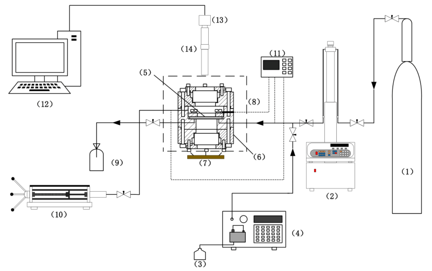
2. Experimental Section
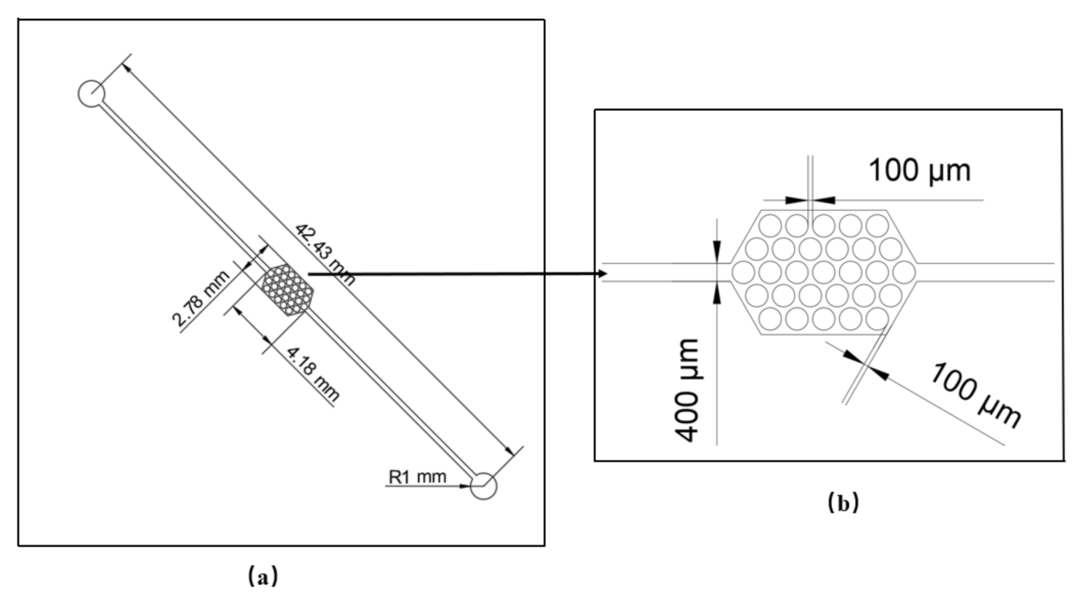
2.1. Materials

Methane and deionized water were used in this study to generate methane hydrate in a microfluidic chip. The microfluidic chip was made of glass (Suzhou Wenhao Microfluidic Technology Co., LTD, China.). The dimensions and structure are shown in Figure 1a,b. Figure 1b is the enlarged image of the section of microfluidic chip with the porous structure. The width of the flow inlet channel is 400 μm. The minimum width of the pore is 100 μm. The depth of the pore channel is 20 μm.

2.2. Methods

Figure 2 presents the experimental setup. A two-dimensional glass microfluidic chip was located in a high-pressure jacket. The high-pressure jacket was filled with water from a high-pressure pump to provide surrounding pressure for the glass microfluidic chip. The methane and water were co-injected into the glass microfluidic chip by gas and liquid high-pressure syringe pumps. The high-pressure microfluidic syringe pump was employed to control the system pressure. The pressure range in this study was from 4.05 MPa to 5.91 MPa. Due to the porous structure of the microfluidic chip shown in Figure 1, methane bubbles could be dispersed and trapped in the pore throats. The formation and growth processes of methane hydrate were investigated under quiescent conditions in this work, so a hydrate seed was employed to induce quick hydrate formation. This could therefore shorten the induction period of hydrate formation. A cooling bath can be used to provide low-temperature conditions. The system temperature was first set to be below zero for the ice forming. The temperature was then elevated to above zero to melt the ice, and the hydrate formed simultaneously. The temperature was continuously elevated to the temperature of hydrate dissociation. Some methane hydrates started to dissociate, but some methane hydrates were not dissociated since they might be under a metastable state during the phase change. The temperature was then cooled down for the hydrate formation. The undissociated hydrate could induce hydrate formation. The microscopic images of the processes and morphologies of the methane hydrate film were captured by a microscope (Changrong S-T, China) with a high-resolution digital camera (Aptina-LV500, China). The lateral film growth rates of methane hydrate (v) on pore interior surfaces can be determined by measuring the areas of the hydrate film (A) at different growth times (t). The hydrate film area was analyzed by image processing software (Image-Pro Plus, 6.0).
Driving force can be regarded as one of the crucial factors controlling the nucleation and film growth of a hydrate. With respect to the driving force of hydrate growth kinetics, several forms of driving forces were defined. For instance, T eq T exp [20], μ wH exp μ wL exp [21] and f i exp / f i eq 1 [22] were selected to indicate the driving force for hydrate nucleation, growth and formation. A more general molar dimensionless parameter ( Δ G / RT ) in terms of Gibbs free energy difference was used in this study to describe the driving force on methane hydrate film formation. The Gibbs free energy difference was obtained according to the Chen–Guo model [23]. The process of basic hydrate formation could be presented by the following reaction:
H 2 O + λ 2 G G λ 2 · H 2 O
where λ 2 is the gas molecule number per water molecule, and G stands for the gas species. The Gibbs free energy difference ( Δ G ) can be calculated by
Δ G = μ B μ w λ 2 μ g
μ B = μ B 0 + λ 1 RT 1 θ
μ g = μ g 0 T + RT ln f
where μ g , μ w and μ B are chemical potentials of gas, water and basic hydrate, respectively; θ is the fraction of the linked cavities occupied by gas molecules; λ 1 represents the number of linked cavities per water molecule in the basic hydrate; μ g 0 T and μ B 0 stand for the chemical potentials of the ideal gas state and unfilled basic hydrate ( θ = 0 ), respectively; and f is the fugacity of gas species [23]. Combing Equations (2)–(4), the Gibbs free energy difference ( Δ G ) can be expressed as
Δ G = μ B 0 μ w λ 2 μ g 0 + λ 1 RT ln 1 θ λ 2 RT ln f
According to the definition of f 0 in the Chen–Guo model [23], the following expression can be obtained:
μ B 0 μ w λ 2 μ g 0 = λ 2 RT ln f 0
Combining the Equations (5) and (6), the Gibbs free energy difference ( Δ G ) can be obtained:
Δ G = λ 2 ln f 0 f + λ 1 ln 1 θ
where f 0 represents the fugacity of the gas phase in equilibrium with the unfilled basic hydrate, which is a function of temperature and can be calculated by an Antoine-type equation [23].

3. Results and Discussion

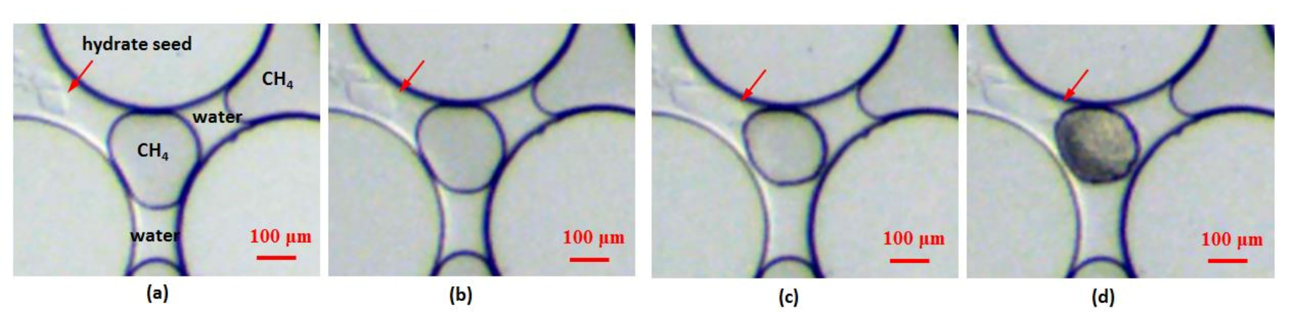
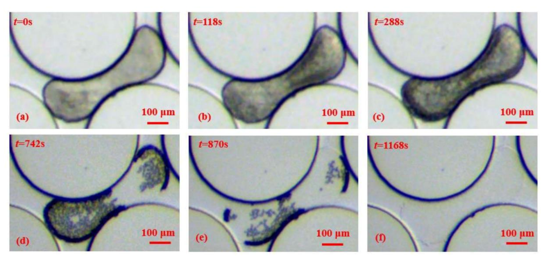
3.1. The Formation Process of Methane Hydrate Induced by Hydrate Seed in Pores

To shorten the induction period of hydrate formation, a hydrate crystal seed was introduced into the micromodel to induce methane hydrate formation. Figure 3a–d presents the process of a hydrate crystal seed inducing the formation of methane hydrate. It could be seen that some undissociated hydrates still existed, since they might be under a metastable state during the phase change when the hydrate dissociation temperature is reached, as shown in the red arrow in Figure 3a. As the temperature decreased to below the hydrate equilibrium temperature, the undissociated hydrate seed continuously grew in the pore space, as indicated in Figure 3b–d. Meanwhile, it was observed that the size of the methane bubble surrounding the hydrate shrunk. The methane hydrate crystal grew with the existing surrounding methane that had dissolved in the water. The dissolved methane consumption for hydrate crystal growth could result in a methane concentration gradient between the water close to the hydrate and the methane phase. The concentration of dissolved methane surrounding the hydrate could be lower than that near the bulk methane bubble. This could cause the migration of dissolved methane near the methane bubble to the methane hydrate crystal. The methane in the bulk methane bubble was continuously dissolved, and the methane bubble became smaller. The methane hydrate crystal simultaneously grew and finally reached the water–methane interface to induce the lateral growth of a methane hydrate film in the glass pores. The hydrate shell formed on the methane bubble could be visualized at the pore scale (Figure 3d).

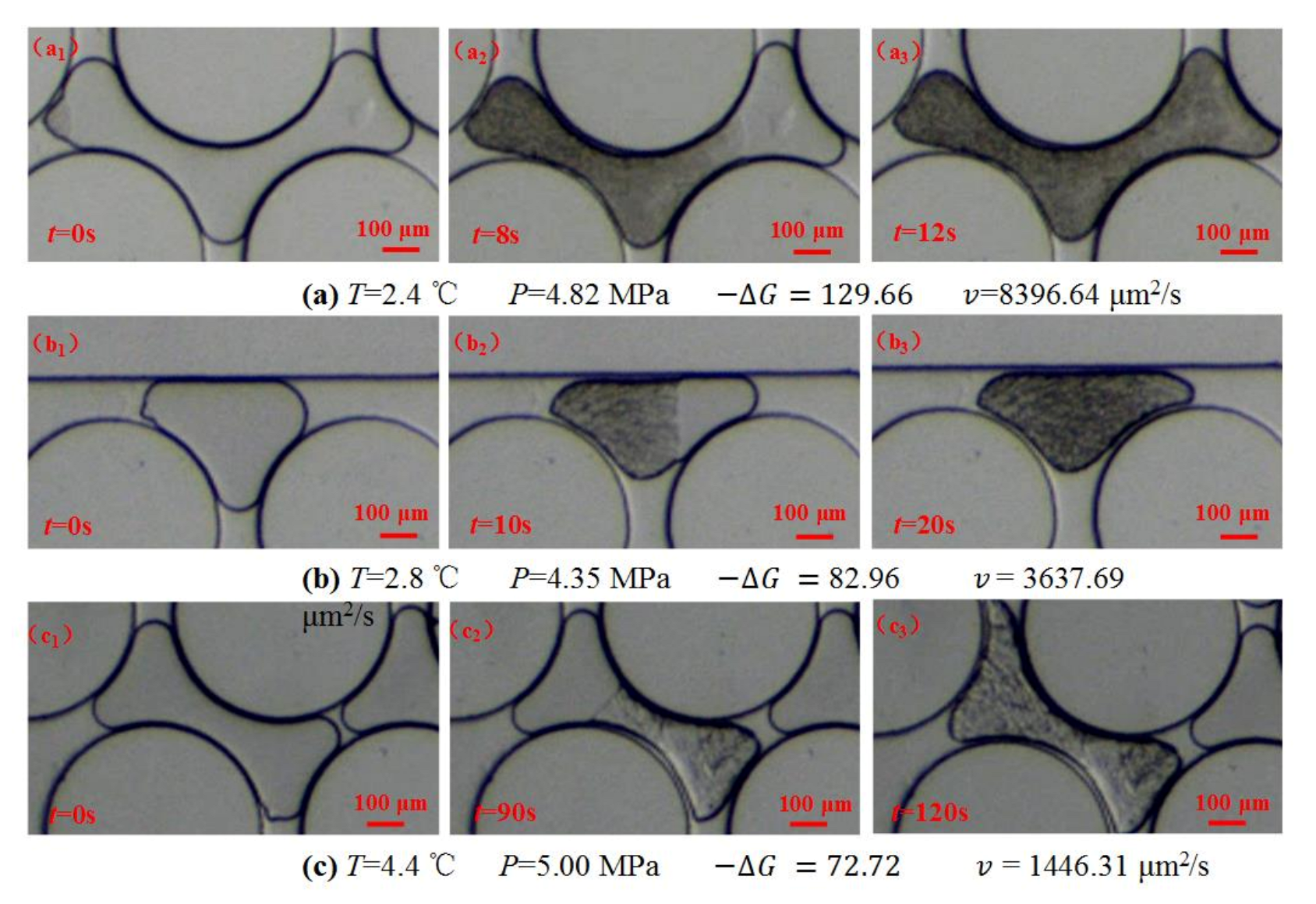
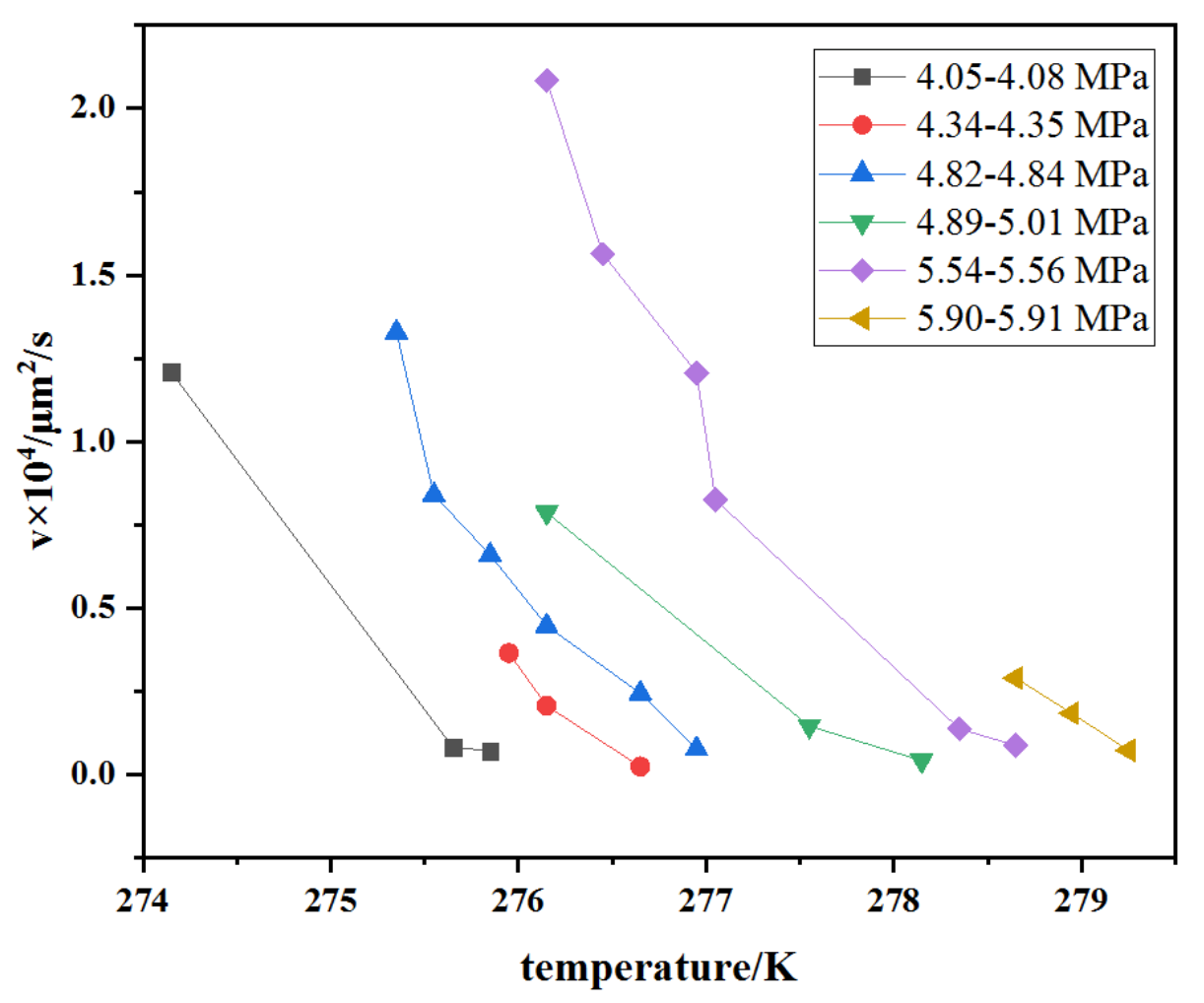
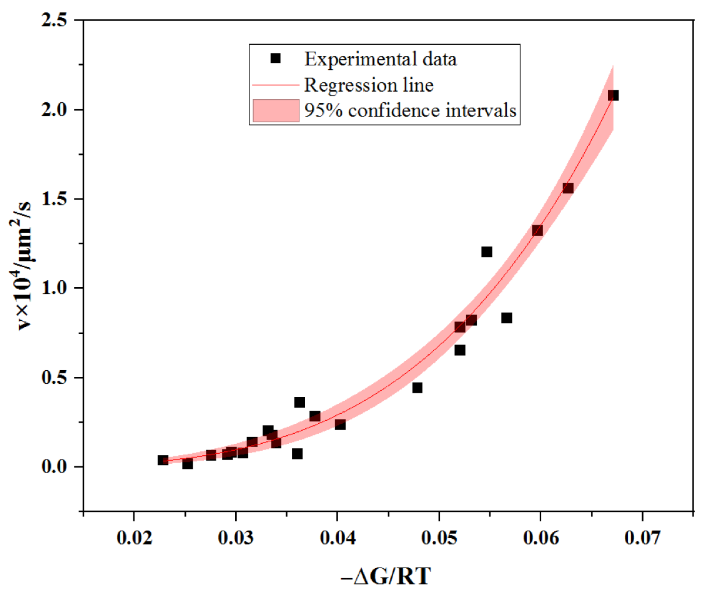
3.2. The Kinetics of the Lateral Growth of Methane Hydrate Film in Pores

In this study, the kinetics of the lateral growth process of methane hydrate film in pores was investigated by measuring the lateral film growth rate on the glass pore interior surface. The lateral film growth rate was calculated by the surface area variation in the formed film on the methane bubble at various times during the lateral growth of the hydrate film. The kinetics of the lateral film growth of methane hydrate was measured at various pressures and temperatures under different driving forces. Figure 4 indicates the typical evolutional morphologies of the lateral film growth at different driving forces. The methane hydrate film laterally grew between the methane bubble surface and glass pore interior surface (Figure 4). As the growth time elapsed, the hydrate film gradually spread and encapsulated the whole methane bubble, finally forming a hydrate shell. The morphological images also indicate a higher driving force leading to faster lateral film growth. The film morphological characteristics of the hydrate were also visually reflected at different driving forces in the pore interiors (Figure 4). Figure 4a indicates that the surface of methane hydrate film was smooth at high driving force in terms of low temperature and high pressure. As the driving force decreased, different hydrate film morphologies could be observed. Rough and coarse hydrate films could be obtained at low driving forces (Figure 4b,c).
Figure 5 shows the relationship between the lateral film growth rate and temperature/pressure. The results indicate that the lateral film growth rate decreases with an increase in temperature for similar system pressures. It can be also seen from the data trends that high pressure contributes to the high lateral film growth rate at the same temperature.
In this study, the dimensionless parameter Δ G / RT was applied, which is a more generic form to express and quantify the driving force of hydrate formation. The reaction rate was exponentially correlated with the Gibbs free energy change ( Δ G / RT ) [1]. Herein, the lateral film growth rate in pore interiors was correlated with the driving force ( Δ G / RT ). As shown in Figure 6, a great exponential fitting (v = k Δ G / RT n ) was obtained between the lateral film growth rate (v) and driving force ( Δ G / RT ) on the pore inner surface. This finding is in agreement with the previous study [1]. The exponential fitting parameters of k and n were 5.56 × 104 μm2/s and 3.77, respectively. Moreover, this could contribute to the development of the modelling of methane hydrate film growth kinetics in a pore.

3.3. The Morphological Characteristics of Film Thickening Growth in Pores

The thickening growth process of methane hydrate film was also visualized at the pore scale. The hydrate film thickening growth was accomplished along with lateral film growth. Figure 7a–f shows the morphological evolution of the hydrate film thickening growth at a temperature of 1 °C and pressure of 4.59 MPa. Figure 7a indicates the completion of the lateral film growth in pores. With the increasing thickness of hydrate film, the color of hydrate film became optically darker because of the lower transmittance, as shown in Figure 7a–c. In most previous studies, the macroscopic experiments generated a gas bubble suspended in the water phase [1,3]. The guest gas phase could not be completely consumed by the hydrate film growth at the end of experiments due to the large size of the gas phase. In this study, a glass micromodel with a porous structure was employed to mimic the hydrate sediments. The gas bubbles trapped in the pore throat are with small sizes at a pore scale. This could lead to the completion of methane consumption for the thickening growth of methane hydrate film in pores. Figure 7d–f show the process of the consumption of gas bubbles encapsulated in the hydrate shell. When the guest gas was entirely consumed, transparent hydrate crystals were formed and trapped in the pore, plugging the pore throat.
At the completion of the lateral growth of the hydrate film, the formed hydrate film barrier started to isolate the guest phase, making contact with the water phase. Meanwhile, the thickening growth of the hydrate film was initiated. The diffusion process of guest [24] or water [25,26] molecules across the formed hydrate film could be the key controlling step on the mass transfer mechanism of hydrate film formation. Even through the phenomenon of film thickening growth has been widely confirmed, it is still controversial whether gas or water diffuses across the hydrate film for film thickening growth [25]. This is highly important since it determines the driving force and controls the mass transfer mechanism of the methane hydrate growth process [25]. Thus, in this study, the microfluidic device was used to directly observe fluid transport behavior through the formed hydrate crystal film during the film thickening growth of methane hydrate in confined pores. Figure 7d–f show that the outer edge of the hydrate shell did not extend and grow outwards during the film thickening growth process. The final outline of the hydrate crystal (Figure 7f) almost stays the same as that prior to the occurrence of film thickening growth (Figure 7c). This could indicate that methane gas does not transport across the hydrate film to make contact with the water for hydrate growth. Instead, the microscopic visual results could support the higher mobility of water molecules diffusing through the porous hydrate phase. These results confirm that the film thickening growth of methane hydrate is mainly dominated by the diffusion of water molecules through the hydrate crystal film in confined pores (Figure 7d,e).

4. Conclusions

A solid understanding of the methane hydrate formation mechanism is highly important for natural gas hydrate exploration and hydrate-related utilization. In this study, a glass microfluidic chip with a porous structure was employed to carry out a direct visual study on the film growth process of methane hydrate and to measure the film growth kinetics on the glass pore inner surfaces in a small, confined porous space. The lateral film growth kinetics and morphology on the glass pore interior surface were directly investigated and visualized. The driving force of a dimensionless parameter (−ΔG/(RT)) was correlated to the lateral film growth rate to describe the film growth kinetics of methane hydrate in confined pores. The thickening film growth process was also directly visualized in micropores. The microscopic images and results indicate that the film thickening growth of methane hydrate is mainly dominated by the diffusion of water molecules through hydrate film in glass-confined pores.

Author Contributions

Conceptualization, X.L.; methodology, X.L. and C.W.; software, C.W.; validation, C.W.; formal analysis, X.L.; investigation, X.L. and C.W.; resources, Q.L., Q.F., G.C. and C.S.; data curation, X.L. and C.W.; writing—original draft, X.L.; writing—review & editing, X.L.; visualization, X.L.; supervision, X.L.; project administration, X.L., Q.L. and Q.F.; funding acquisition, X.L., Q.L., G.C. and C.S. All authors have read and agreed to the published version of the manuscript.

Funding

This work was supported by the National Natural Science Foundation of China (21808238, U19B2005, 21636009) and the National Key Research and Development Program of China (2017YFC0307302).

Institutional Review Board Statement

Not applicable.

Informed Consent Statement

Not applicable.

Data Availability Statement

Not applicable.

Acknowledgments

The author would like to thank the National Natural Science Foundation of China (21808238, U19B2005, 21636009) and the National Key Research and Development Program of China (2017YFC0307302).

Conflicts of Interest

The authors declare no conflict of interest.

References

  1. Sun, C.-Y.; Chen, G.-J.; Ma, C.-F.; Huang, Q.; Luo, H.; Li, Q.-P. The growth kinetics of hydrate film on the surface of gas bubble suspended in water or aqueous surfactant solution. J. Cryst. Growth 2007, 306, 491–499. [Google Scholar] [CrossRef]
  2. Leopércio, B.C.; de Souza Mendes, P.R.; Fuller, G.G. Growth Kinetics and Mechanics of Hydrate Films by Interfacial Rheology. Langmuir 2016, 32, 4203–4209. [Google Scholar] [CrossRef] [PubMed]
  3. Li, S.-L.; Sun, C.-Y.; Liu, B.; Li, Z.-Y.; Chen, G.-J.; Sum, A.K. New Observations and Insights into the Morphology and Growth Kinetics of Hydrate Films. Sci. Rep. 2014, 4, 4129. [Google Scholar] [CrossRef] [PubMed] [Green Version]
  4. Vlasov, V.A.; Nesterov, A.N.; Reshetnikov, A.M. Kinetics of Gas Hydrate Film Growth along the Water–Gas Interface. Russ. J. Phys. Chem. A 2020, 94, 1949–1951. [Google Scholar] [CrossRef]
  5. Zeng, X.; Wu, G.; Wang, J.; Yang, C.; Meng, Q.; Chen, G.; Chen, D. Effects of inhibitors on the morphology and kinetics of hydrate growth on surface of bubble. J. Nat. Gas Sci. Eng. 2020, 74, 103096. [Google Scholar] [CrossRef]
  6. Mori, Y.H. Estimating the thickness of hydrate films from their lateral growth rates: Application of a simplified heat transfer model. J. Cryst. Growth 2001, 223, 206–212. [Google Scholar] [CrossRef]
  7. Mochizuki, T.; Mori, Y.H. Clathrate-hydrate film growth along water/hydrate-former phase boundaries—Numerical heat-transfer study. J. Cryst. Growth 2006, 290, 642–652. [Google Scholar] [CrossRef]
  8. Liu, Z.; Li, H.; Chen, L.; Sun, B. A New Model of and Insight into Hydrate Film Lateral Growth along the Gas–Liquid Interface Considering Natural Convection Heat Transfer. Energy Fuels 2018, 32, 2053–2063. [Google Scholar] [CrossRef]
  9. Kar, A.; Bhati, A.; Acharya, P.V.; Mhadeshwar, A.; Venkataraman, P.; Barckholtz, T.A.; Bahadur, V. Diffusion-based modeling of film growth of hydrates on gas-liquid interfaces. Chem. Eng. Sci. 2021, 234, 116456. [Google Scholar] [CrossRef]
  10. Lee, S.Y.; Kim, H.C.; Lee, J.D. Morphology study of methane–propane clathrate hydrates on the bubble surface in the presence of SDS or PVCap. J. Cryst. Growth 2014, 402, 249–259. [Google Scholar] [CrossRef]
  11. Zeng, X.-Y.; Wu, G.; Zhong, J.-R.; Chen, D.-Y.; Sun, C.-Y.; Chen, G.-J. Three-Scale in Situ Investigation on the Film Morphology and Mass Transfer Channels during the Thickening Growth of Hydrates on Gas Bubble. Cryst. Growth Des. 2019, 19, 3158–3165. [Google Scholar] [CrossRef]
  12. Li, S.-L.; Sun, C.-Y.; Liu, B.; Feng, X.-J.; Li, F.-G.; Chen, L.-T.; Chen, G.-J. Initial thickness measurements and insights into crystal growth of methane hydrate film. AIChE J. 2013, 59, 2145–2154. [Google Scholar] [CrossRef]
  13. Uchida, T.; Ebinuma, T.; Kawabata, J.; Narita, H. Microscopic observations of formation processes of clathrate-hydrate films at an interface between water and carbon dioxide. J. Cryst. Growth 1999, 204, 348–356. [Google Scholar] [CrossRef]
  14. Li, S.-L.; Wang, Y.-F.; Sun, C.-Y.; Chen, G.-J.; Liu, B.; Li, Z.-Y.; Ma, Q.-L. Factors controlling hydrate film growth at water/oil interfaces. Chem. Eng. Sci. 2015, 135, 412–420. [Google Scholar] [CrossRef]
  15. Beltrán, J.G.; Servio, P. Morphological Investigations of Methane−Hydrate Films Formed on a Glass Surface. Cryst. Growth Des. 2010, 10, 4339–4347. [Google Scholar] [CrossRef]
  16. Nagashima, H.D.; Oshima, M.; Jin, Y. Film-growth rates of methane hydrate on ice surfaces. J. Cryst. Growth 2020, 537, 125595. [Google Scholar] [CrossRef]
  17. Kishimoto, M.; Iijima, S.; Ohmura, R. Crystal Growth of Clathrate Hydrate at the Interface between Seawater and Hydrophobic-Guest Liquid: Effect of Elevated Salt Concentration. Ind. Eng. Chem. Res. 2012, 51, 5224–5229. [Google Scholar] [CrossRef]
  18. Adamova, T.P.; Stoporev, A.S.; Manakov, A.Y. Visual Studies of Methane Hydrate Formation on the Water–Oil Boundaries. Cryst. Growth Des. 2018, 18, 6713–6722. [Google Scholar] [CrossRef]
  19. Zhang, G.; Liu, B.; Xu, L.; Zhang, R.; He, Y.; Wang, F. How porous surfaces influence the nucleation and growth of methane hydrates. Fuel 2021, 291, 120142. [Google Scholar] [CrossRef]
  20. Vysniauskas, A.; Bishnoi, P.R. A kinetic study of methane hydrate formation. Chem. Eng. Sci. 1983, 38, 1061–1072. [Google Scholar] [CrossRef]
  21. Skovborg, P.; Ng, H.J.; Rasmussen, P.; Mohn, U. Measurement of induction times for the formation of methane and ethane gas hydrates. Chem. Eng. Sci. 1993, 48, 445–453. [Google Scholar] [CrossRef]
  22. Natarajan, V.; Bishnoi, P.R.; Kalogerakis, N. Induction phenomena in gas hydrate nucleation. Chem. Eng. Sci. 1994, 49, 2075–2087. [Google Scholar] [CrossRef]
  23. Chen, G.-J.; Guo, T.-M. A new approach to gas hydrate modelling. Chem. Eng. J. 1998, 71, 145–151. [Google Scholar] [CrossRef]
  24. Henning, R.W.; Schultz, A.J.; Thieu, V.; Halpern, Y. Neutron Diffraction Studies of CO2 Clathrate Hydrate: Formation from Deuterated Ice. J. Phys. Chem. A 2000, 104, 5066–5071. [Google Scholar] [CrossRef]
  25. Davies, S.R.; Sloan, E.D.; Sum, A.K.; Koh, C.A. In Situ Studies of the Mass Transfer Mechanism across a Methane Hydrate Film Using High-Resolution Confocal Raman Spectroscopy. J. Phys. Chem. C 2010, 114, 1173–1180. [Google Scholar] [CrossRef]
  26. Liang, S.; Kusalik, P.G. The Mobility of Water Molecules through Gas Hydrates. J. Am. Chem. Soc. 2011, 133, 1870–1876. [Google Scholar] [CrossRef]
Figure 1. Dimension and structure of the glass microfluidic chip.
Energies 14 06814 g001
Figure 2. Experimental setup: (1) methane, (2) high-pressure microfluidic gas pump, (3) water tank, (4) high-pressure microfluidic water pump, (5) porous glass microfluidic chip, (6) high-pressure jacket (microfluidic chip holder), (7) light source, (8) cooling water bath, (9) gas/liquid recovery tank, (10) high-pressure pump, (11) temperature and pressure acquisition system, (12) data and image acquisition system, (13) CCD, (14) microscope.
Energies 14 06814 g002
Figure 3. Microscopic images of methane hydrate formation process induced by hydrate seed in pores.
Energies 14 06814 g003
Figure 4. The typical evolutional morphological microscopic images of the lateral film growth at different driving forces (a) T = 2.4 °C, P = 4.82 MPa; (b) T = 2.8 °C, P = 4.35 MPa; (c) T = 4.4 °C, P = 5.00 MPa.
Energies 14 06814 g004
Figure 5. Lateral film growth rates at different temperatures and pressures.
Energies 14 06814 g005
Figure 6. Lateral film growth rates for various Gibbs free energy difference (−∆G/RT).
Energies 14 06814 g006
Figure 7. The morphological evolution of film thickening growth in pores at different times (af).
Energies 14 06814 g007
Publisher’s Note: MDPI stays neutral with regard to jurisdictional claims in published maps and institutional affiliations.

