Article

An Analytical Method for Calculating the Cogging Torque of a Consequent Pole Hybrid Excitation Synchronous Machine Based on Spatial 3D Field Simplification

1
School of Electrical and Information Engineering, Zhengzhou University of Light Industry, Zhengzhou 450002, China
2
School of Building Environment Engineering, Zhengzhou University of Light Industry, Zhengzhou 450002, China
*
Author to whom correspondence should be addressed.
Energies 2022, 15(3), 878; https://doi.org/10.3390/en15030878
Submission received: 18 December 2021 / Revised: 22 January 2022 / Accepted: 23 January 2022 / Published: 25 January 2022

Abstract

:
Consequent pole hybrid excitation synchronous (CPHES) machines have the advantage of symmetrical bidirectional magnetomotive force increments. Compared with a traditional hybrid excitation motor (HEM), a CPHES machine improves the disadvantage of asymmetry in the adjustment range when magnetization and demagnetization occur. The calculation and analysis of the cogging torque of the CPHES machine are complex due to the complicated structure. This paper proposes an analytical method for calculating the cogging torque of a CPHES machine. This analytical method converts the complex three-dimensional magnetic field problem into a two-dimensional magnetic circuit problem and, through the accumulation method, can quickly and accurately calculate the cogging torque of the CPHES machine. In contrast with the finite element method, the calculation results basically follow each other, but the analytical method is more efficient and omits complicated meshing. This is of great significance to the preliminary electromagnetic design and performance optimization of a CPHES machine.

1. Introduction

The main magnetic field of a hybrid excitation motor (HEM) is jointly generated by the permanent magnet (PM) and the electric excitation winding, which can ensure high efficiency and realize the adjustment and control of the main magnetic field, thereby improving the speed range and driving performance of the motor, which is widely used in electric vehicles and other applications [1]. However, the traditional HEM has the defect of asymmetry of the bidirectional magnetomotive force (MMF) increment, limiting the motor’s speed adjustment range. A consequent pole hybrid excitation synchronous (CPHES) machine solves this problem and further improves the speed adjustment performance of the HEM [2]. This means that electric vehicles or aeronautic facilities equipped with CPHES machines have more flexible speed control. Moreover, the consequent pole structure reduces the requirement of rare earth material; it also avoids the PM demagnetization caused by the magnetization process and increases the service life of the motor. However, a motor with a consequent pole structure has an asymmetric air gap field, and the positive and negative asymmetry of the air gap flux density leads to a large number of even harmonics [3,4]. The cogging torque of a motor is defined as the change of the air gap field energy with respect to the position angle of the rotor, which causes the fluctuation of the motor output torque, especially when the motor is running at a low speed [5]. Compared with the traditional PM motor with only odd harmonics in the air gap field, the consequent pole structure motor with even harmonic air gap magnetic field has an exceptionally complex cogging torque generation [6]. Considering the many application domains of CPHES machines, especially in high-performance drive applications, reducing cogging torque is very important for motor design [7]. At present, the approach for reducing cogging torque mainly includes modifying the motor’s structural parameters and designing a control algorithm to absorb the effects of the magnetic interaction between rotor and stator [8,9].
However, it has always been difficult to calculate the cogging torque with a complex three-dimensional structure such as a CPHES machine. The field analysis is an important method for calculating the cogging torque. Its essence is to calculate the energy change in the air gap concerning the rotation angle. Cogging torque is determined by many factors, such as pole slot structure, PM remanence, PM dimensions, assembling position, and stator slot width [10]. Therefore, the application of the field analysis method must be based on the structure and characteristics of the machine to obtain more accurate analysis results. Yang [11] established the rotor reference system and the stator reference system when analyzing the cogging torque. Considering the influence of the stator slot effects and the rotor saliency effects, the air gap permeance model is divided into stator/rotor air gap permeance models. More accurate calculation results are obtained. Vicente [12] sliced the rotor sector of the axial-flux permanent-magnet motors and got the analytical model of the air gap field with different thicknesses of PMs at different rotation angles, achieving weakening of the cogging torque of the motor by changing the shape of the PMs. Li [13] established tangential and radial field analysis models for PMs to synthesize the electromagnetic energy of the air gap. In short, the field analysis method will become particularly complicated when dealing with complex motor structures. Therefore, it is necessary to simplify the complex three-dimensional magnetic field.
The finite element method (FEM) is mainly used to analyze the cogging torque of the motor. The FEM is a crucial numerical calculation method in computational electromagnetics. Its basic concept is to divide the solution domain into a finite number of subdomains. These subdomains are set as computing units and then established as functions on each unit to transform the original solution domain function into a combination of functions defined on each unit. These functions are further transformed into a matrix equation [14]. Theoretically, the smaller the size of the division unit is, the closer the finite element numerical solution is to the real solution of the physical problem [15]. However, in practical applications, the time required to solve the finite element equation increases sharply with increasing matrix order n [16]. Moreover, the meshing problem and the model singularity problem show that using the FEM to analyze the cogging torque of a complex three-dimensional (3D) structure motor has certain limitations.
Meshing has been a problem facing the development of high-precision FEMs. The traditional FEM has higher quality requirements for traditional four-node quadrilateral elements and eight-node quadrilateral elements. “Deformed” meshes can produce incorrect Jacobian matrices [17], which reduce the accuracy of the solution. Demenko et al. [18] used the FEM to calculate the force of a PM in a system and found that when the grid is unevenly distributed, the calculation relative error increases. This problem is because traditional FEM meshing technology is based on the isoparametric coordinate method. This type of linear displacement interpolation element technology cannot accurately describe the bending deformation that occurs on the element boundary. Therefore, in the structure of complex geometric shapes, the problem of mesh distortion is inevitable. For this type of meshing technology, element deformity will make the Jacobian matrix determinant abnormal, significantly reducing the element’s calculation performance in the deformed grid [19]. Jin et al. [20] showed that when dealing with the vector electromagnetic field problem of a complex three-dimensional structure, a solution with no physical meaning will be produced when the traditional FEM solution is used, which will seriously affect the calculation accuracy. To address the problem of grid distortion, some optimization schemes were proposed in [21,22,23], but the computational efficiency of these methods or their application in low-order elements are limited.
In addition, the traditional FEM cannot handle the singularity of the field at the corner edges and sharp points of conductors and materials [24]. Marechal et al. [25] dealt with an electrostatic field problem using the FEM; the calculation error of the FEM was significantly increased due to the singularity at the corner, and the efficiency was appreciably reduced. This defect is pronounced when the FEM processes complex three-dimensional structures, and any increase in singularity will introduce or amplify FEM calculation errors. To ensure the accuracy of the solution, extremely meticulous meshes have to be divided at the singular points, which presents a huge challenge to the meshing and consumes considerable time. Wen et al. [26] illustrated the construction principles of traditional tetrahedral elements in a 3D FEM. When dealing with singularities in 3D structures, these principles place more stringent requirements on the meshing of the elements. Xu and Wang et al. [27,28] used the traditional FEM to solve the singularity problem of an electromagnetic field model. Compared with the extended FEM, the traditional FEM needs to divide more grids to achieve a certain accuracy, which undoubtedly reduces the efficiency.
The FEM, as the mainstream method for calculating the cogging torque of a motor, has a reliable calculation accuracy guarantee. However, the accuracy and efficiency of the calculation are limited by the meshing and model structure when dealing with a complex 3D structure. Because the FEM has difficulty handling complex 3D models, this paper proposes a mathematical model that decomposes and converts an elaborate 3D model into a 2D model and then uses the superposition principle to quickly and accurately calculate the cogging torque of a CPHES machine.

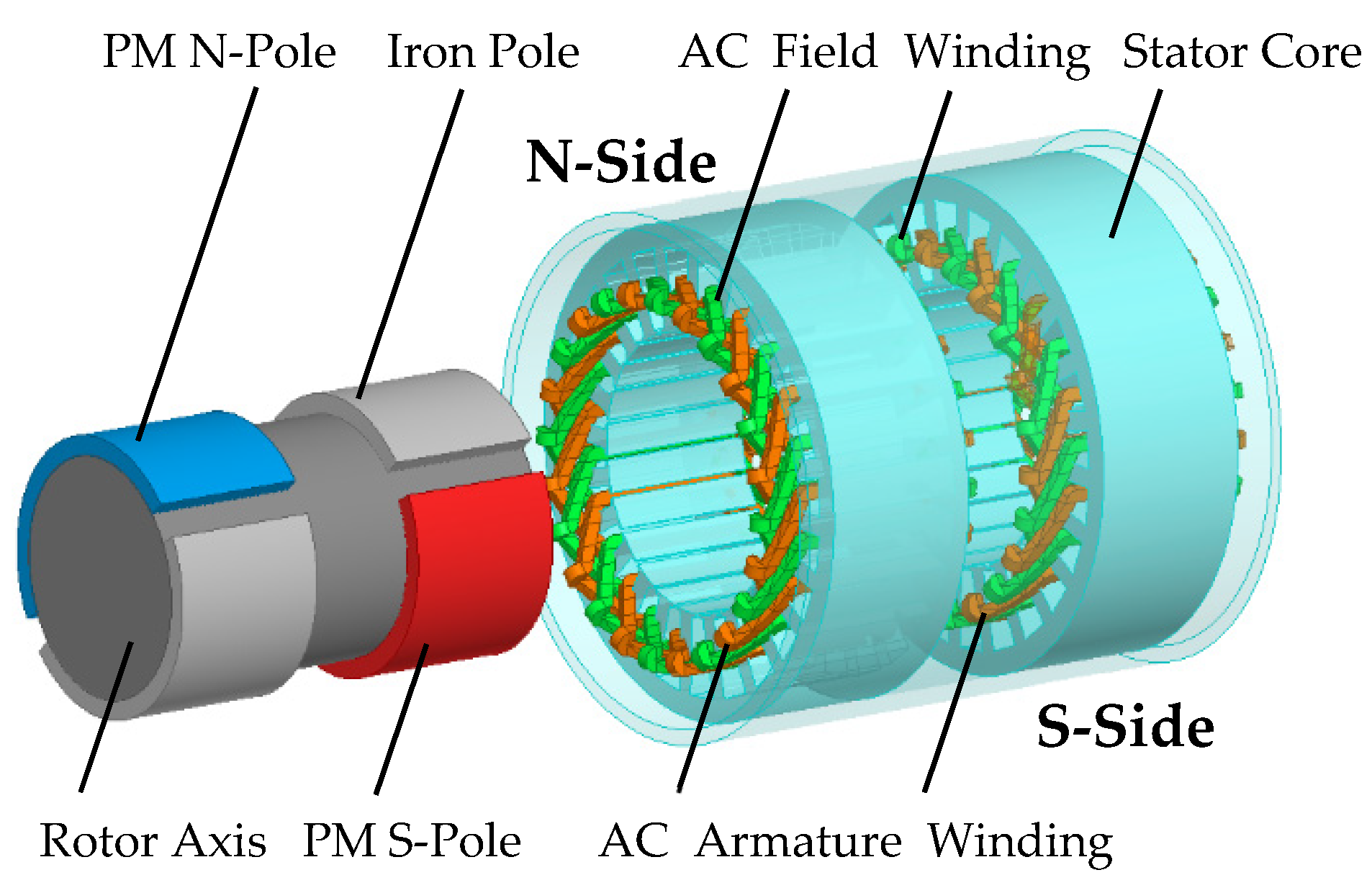
2. The Structure and Principle of a CPHES Machine

A CPHES machine realizes bidirectional MMF incremental symmetry relying on unique motor construction and taking a 24-slot/2-pole CPHES machine as an example, as shown in Figure 1, the motor rotor is divided into two parts, the N-side and S-side, along the axial direction. The PM poles and iron poles of each part are alternately installed on the surface of the rotor. Corresponding to the rotor structure, the stator is also divided into an N-side and S-side in the axial direction. The stator winding contains a field winding and an armature winding. Both of these windings are AC windings. There is no DC field winding in the CPHES structure. Compared with a traditional HEM, the AC field winding of the CPHES machine replaces the conventional DC winding.
In the HEMs, including traditional HEMs and CPHES machines, there are three MMFs noted as F p m , F a and F f , generated by PM poles, armature windings, and field windings, respectively. In the traditional HEMs, when the field winding is supplied with forward or reverse direct current, the field MMF F f is fixed on the d-axis, as shown in Figure 2a,b. Based on the geometric relationship, it is easy to derive the following expression,
F 0 F F + F 0
which indicates the demagnetization is inferior to the magnetization in traditional HEMs. The fundamental reason for this phenomenon is that the MMF produced by the DC field windings acts only on the d-axis. Consequently, the CPHES machine employs alternating current to control the spatial phasor of F f , so that F f and F 0 are in the same phase, therefore the following expression holds,
F 0 F = F + F 0
Then the CPHES machines are equipped with the symmetrical capability of bidirectional field control, as shown in Figure 2c,d. Compared to traditional HEMs, the CPHES machines expand the range of field control and controllable speed.

3. Analytical Model of Cogging Torque in CPHES Machine

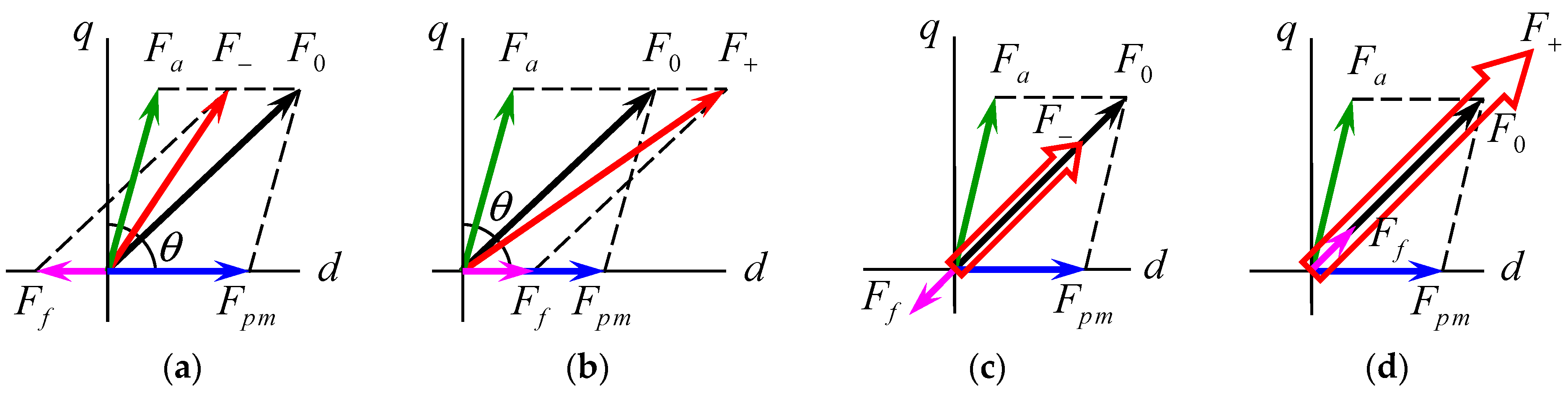
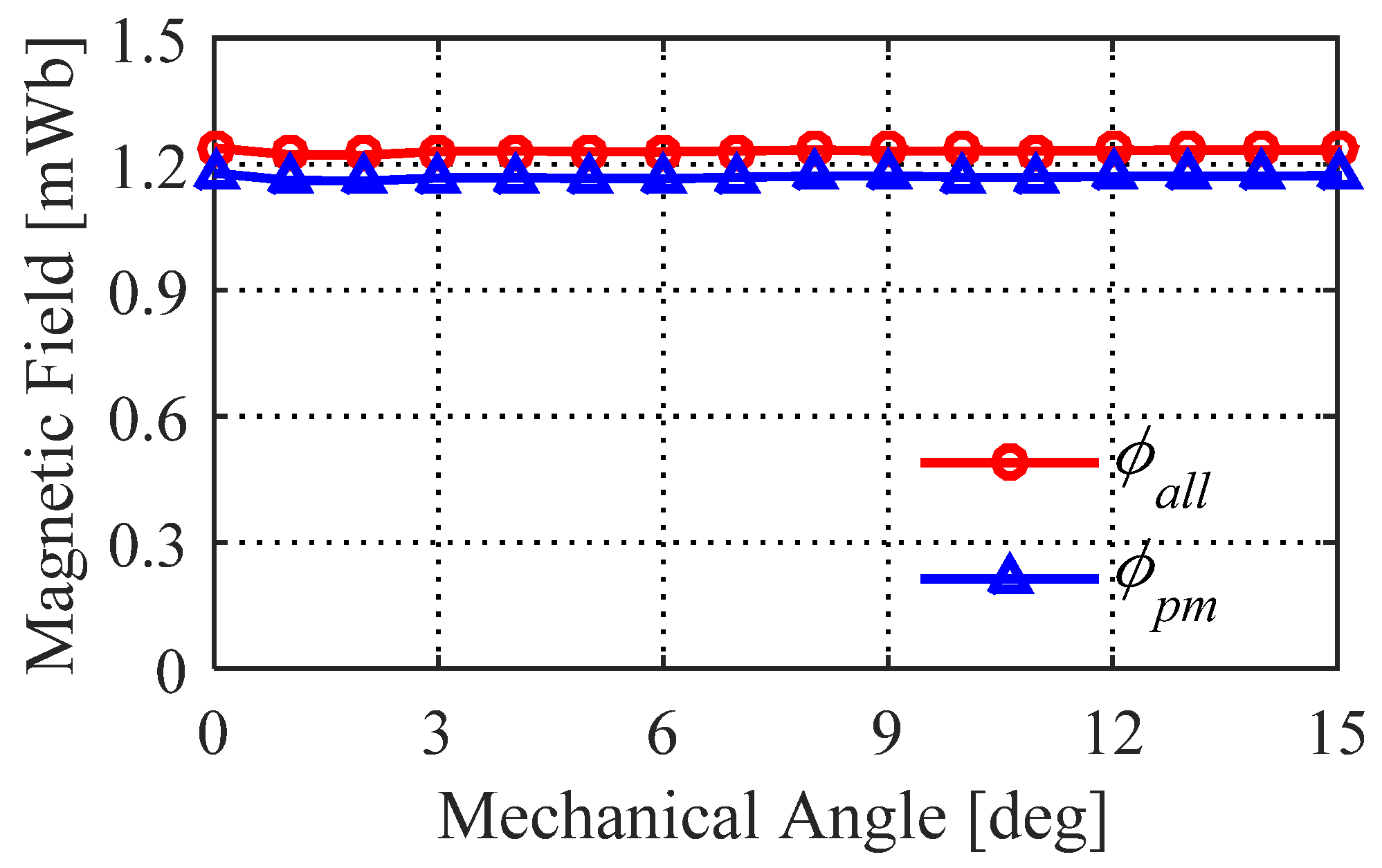
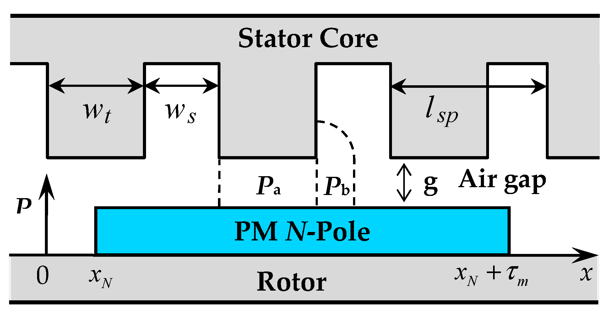
3.1. Simplification of 3D Field

Cogging torque is the interaction force generated by PMs and slot-tooth structure in relative motion. The CPHES machine has special interleaved PMs and iron poles on the rotor. Taking a 6-slot/2-pole CPHES machine as an example, as shown in Figure 3, when the winding is not energized, most of the magnetic flux flows from the PM N-poles to the PM S-poles, and only a few passes occur through the iron pole.
Subsequently, an FEA model of 24-slot/8-pole CPHES machine was built to calculate the magnetic flux distribution over two pole pitches, including a pair of PM poles and iron poles. Its magnetic flux pathway is similar to the above 6-slot/2-pole CPHES machine.
The calculation result is shown in Figure 4. Φall is the magnetic flux passing through a pole-pair pitch, and Φpm is the magnetic flux passing through a PM pole. Φall and Φpm almost maintain constant values. The difference between Φall and Φpm can be approximately regarded as the magnetic flux passing through the iron pole, which can be ignored.
Therefore, when calculating the cogging torque in a period, Φpm can be regarded as a fixed value, and the influence of the ferromagnetic flux on the calculation of the cogging torque can be ignored.

3.2. Two-Dimensional Analysis Model

First, the CPHES machine can be divided into two parts: one part of the rotor has only PM N-poles and iron poles, and the other division of the rotor has only PM S-poles and iron poles. As shown in Figure 5, i is the PM number, the range is (1–Np), where l p is the pole pitch, and Np is the pole-pairs number of the CPHES machine. The stator side is still divided into the N-side and S-side. Due to the characteristics of the cogging torque, when calculating the cogging torque, the armature winding and the field winding of the CPHES machine do not need to be energized, so the double-sided windings in the stator can be ignored.
In this paper, the air gap permeance of all PMs is calculated based on the displacement of each PM on the N-side and S-side relative to the cogging structure, thus obtaining the cogging torque according to the permeability. In accordance with the superposition principle, the total cogging torque of the entire CPHES machine can be obtained. The specific calculation process is shown in Figure 6.

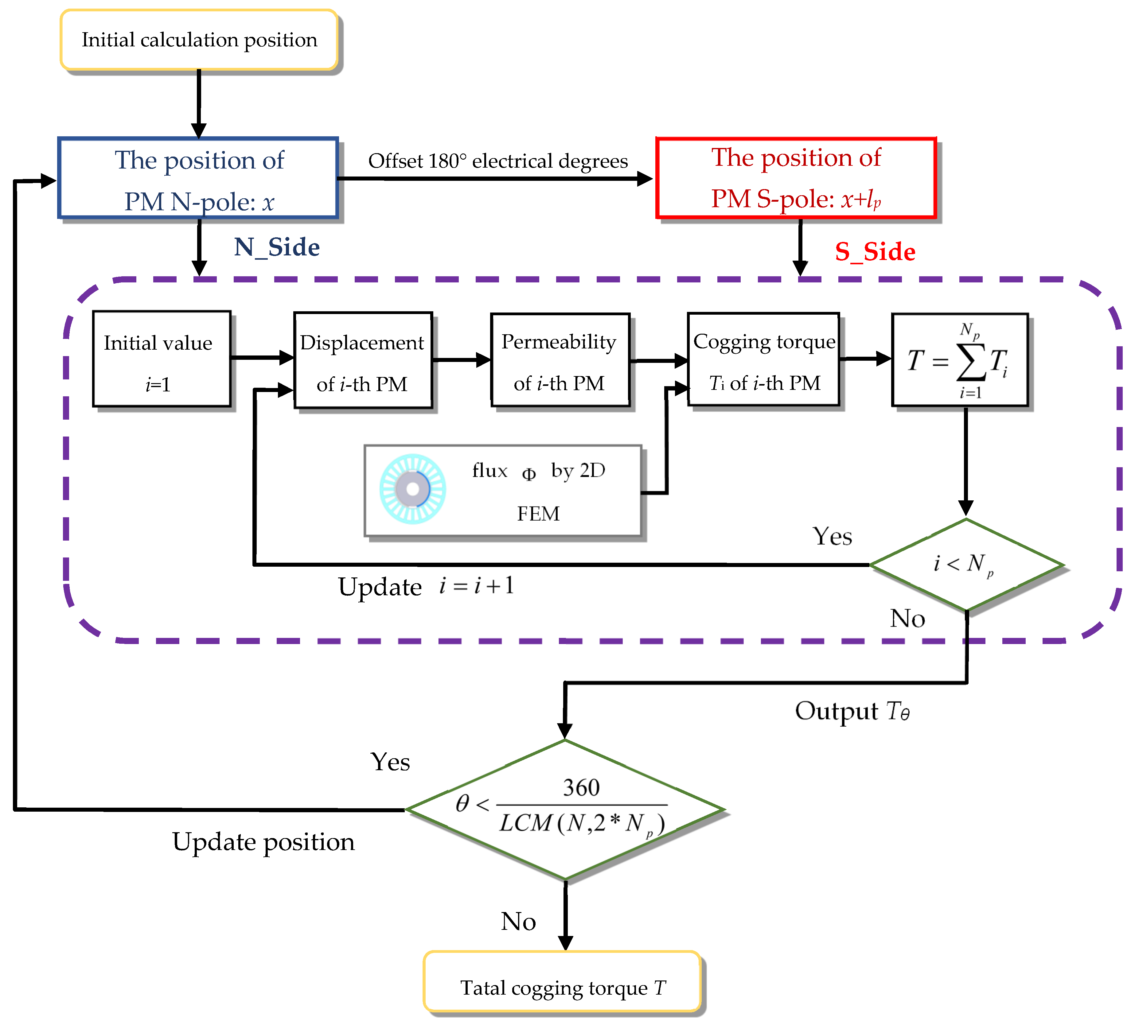
3.3. Calculation Process

Taking into account the magnetic field distribution characteristics at zero current, the simplification is to transfer the complex 3D magnetic field problem of a CPHES machine into two models of the 2D magnetic circuit on the N-side and S-side for analysis. Taking the left arc of a PM-pole on the N-side as the starting point, the cogging torque corresponding to each PM N-pole is derived, and then to all PMs on the S-side is derived based on the spatial relationship between the N- and S-sides. The specific calculation steps are as follows.
The calculation formula of cogging torque is:
T c o g = 1 2 Φ 2 d R d θ
where T c o g is the cogging torque, Φ is the magnetic flux across the air gap, and R is the magnetic resistance through which the magnetic flux passes. According to the relationship between magnetoresistance and permeability: R = 1 P , d R d θ can be further transformed into:
d R d θ = 1 P 2 · d P d x · d x d θ
where P is the permeance, x is the relative displacement, and θ is the mechanical angle, which is defined as the rotation angle corresponding to x.
Assuming that the magnetic circuit is not saturated, the permeance can be obtained by analyzing the air gap permeance model corresponding to the PMs on the N-side. Taking a segment of PM as an example, as shown in Figure 7, let the slot pitch be l s p . The width of the stator teeth is w t , and the slot width of the stator is w t , w t + w s = l s p . The formula for calculating the permeance within a tooth pitch is,
P l s p ( x ) = { μ 0 L x g ( 0 x w t ) μ 0 L w t g + 2 μ 0 L π ln [ 1 + π ( x w t ) 2 g ] ( ( w t x w t + w s 2 ) ) μ 0 L w t g + 2 μ 0 L π ln [ ( 1 + π w s 4 g ) · 4 g + π w s 4 g + 2 π ( 2 l x ) ] ( w t + w s 2 x l s p )
where P l s p is the function of permeance within a tooth pitch. L is the axial length of the N-side. therefore, the analytic formula for the permeance of any segment of PM on the N-side in the CPHES machine at any position is
P i ( x N ) = P m ( x r i g h t ) P m ( x l e f t )
where P i is the permeance of the i-th PM pole. x N is defined as the relative displacement of the PM on the N-side of the CPHES machine. x l e f t / x r i g h t is the relative displacement of the PM pole’s current left arc/right arc in a tooth pitch l s p . P m ( x l e f t ) / P m ( x r i g h t ) is the permeance corresponding to the left arc/right arc of a PM pole.
In Formula (6),
x l e f t = mod [ x L , l s p ]
x r i g h t = mod [ x L + τ m , l s p ]
P m ( x l e f t ) = P l s p ( x l e f t ) + N T S l e f t ( P a + 2 P b )
P m ( x r i g h t ) = P l s p ( x r i g h t ) + N T S r i g h t ( P a + 2 P b )
where x L is the displacement of the i-th PM pole’s left arc in the rotor coordinate system, τ m is the length of the PM pole along the tangential direction, Pa and 2Pb corresponds to the permeance of a stator tooth/slot. NTS indicates the integer number of slot or tooth pitches corresponding to the current position of the left arc/right arc of the PM. Accordingly,
x L = x N + ( i 1 ) × l p
N T S l e f t = f l o o r ( x L l s p )
N T S r i g h t = f l o o r ( x L + τ m l s p )
P a = μ 0 L w t g
P b = 2 μ 0 L π ln ( 1 + π w s 4 g )
Combining the above equations, the air gap permeance P N ( x N ) corresponding to the PM of the N-side rotor in the CPHES machine at any position is obtained as
P N ( x N ) = i = 1 N p P i ( x N )
Thus, the cogging torque T c o g N generated by the N-side is
T c o g N = 1 2 Φ 2 P N ( x N ) d P N ( x N ) d x N d x N d θ
The method of analyzing the cogging torque corresponding to the S-side of the CPHES machine is roughly the same as that of the N-side. Because the S-side PM corresponds to the position of the N-side iron pole in space, as shown in Figure 5, when analyzing the S-side cogging torque, the left arc of the first PM S-pole can be defined as xs in the rotor reference system, which can be expressed in the plane position as
x s = x N + l p
According to the above analysis method of the N-side, the air gap permeance P s ( x s ) corresponding to the PMs on the S-side can be obtained as
P S ( x S ) = i = 1 N p P i ( x S )
Then, the cogging torque T c o g S generated by the S-side is
T c o g S = 1 2 Φ 2 P S ( x S ) d P S ( x S ) d x S d x S d θ
The total cogging torque T c o g of the CPHES machine can be obtained by adding the cogging torque corresponding to the N-side and the S-side.
T c o g = T c o g N + T c o g S

4. Verification

4.1. Dimensional Parameters

To verify the accuracy of the proposed analytical method for calculating the CPHES machine cogging torque, four CPHES machines with different slot/pole combinations were selected as examples for verification. Those combinations include 24-slot/2-pole, 24-slot/4-pole, 24-slot/8-pole and 24-slot/16-pole. Four machine models with different slot/pole combinations were established by analytical methods and 3D FEM. The main parameters of the four models are listed in Table 1.

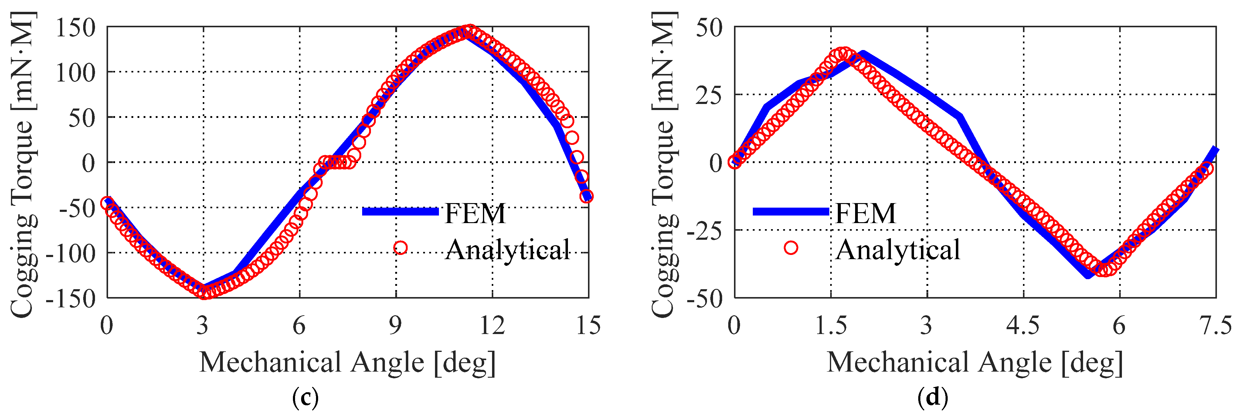
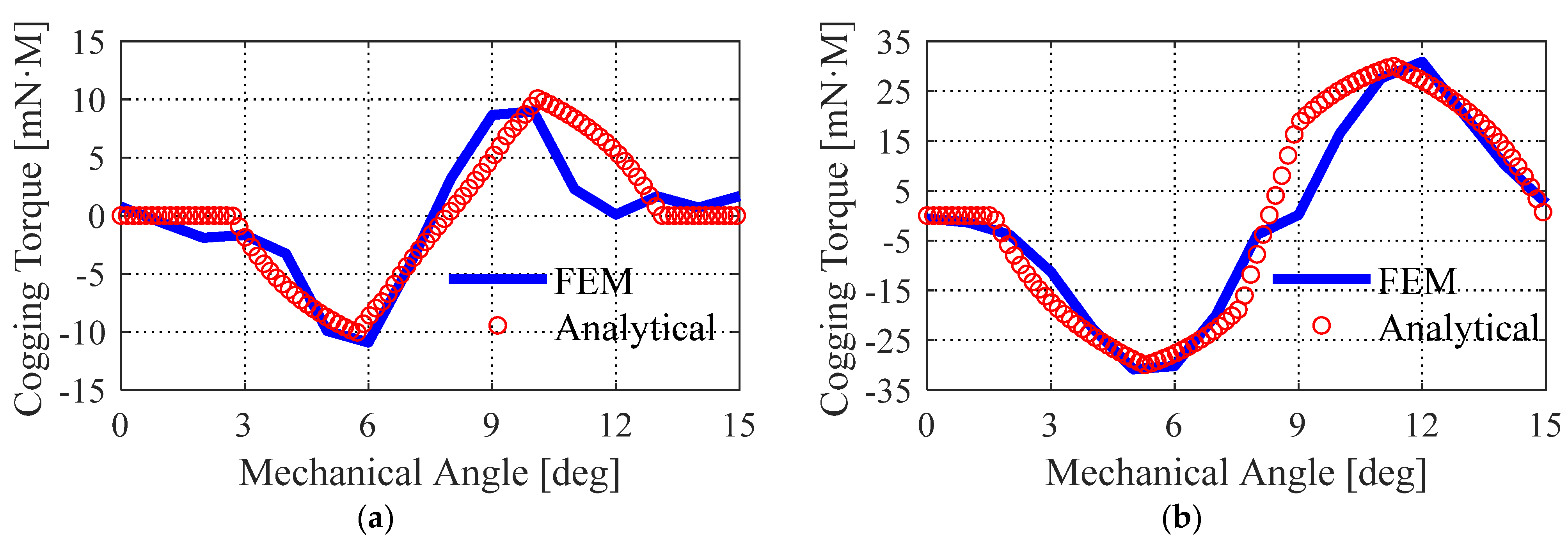
4.2. Comparison of Calculation Results

The cogging torque of the CPHES machine calculated by the FEM and analytical method is consistent under different pole/slot combinations, as shown in Figure 8.
The comparison chart of the CPHES machine cogging torque is calculated by the analysis method and FEM. The analytical method can correctly and rapidly calculate the amplitude and period of the cogging torque of each pole/slot combination, and its analytical accuracy is immensely consistent with the finite element numerical solution. Compared with the traditional FEM, the analytical method does not need to consider the calculation errors caused by the grid division of the motor model, the complicated magnetic poles, and the motor structure. It also economizes considerable time and energy investment to improve the calculation efficiency.
In short, the analytical method proposed in this paper has exceptionally high accuracy and is an efficient method for calculating the cogging torque of a motor.

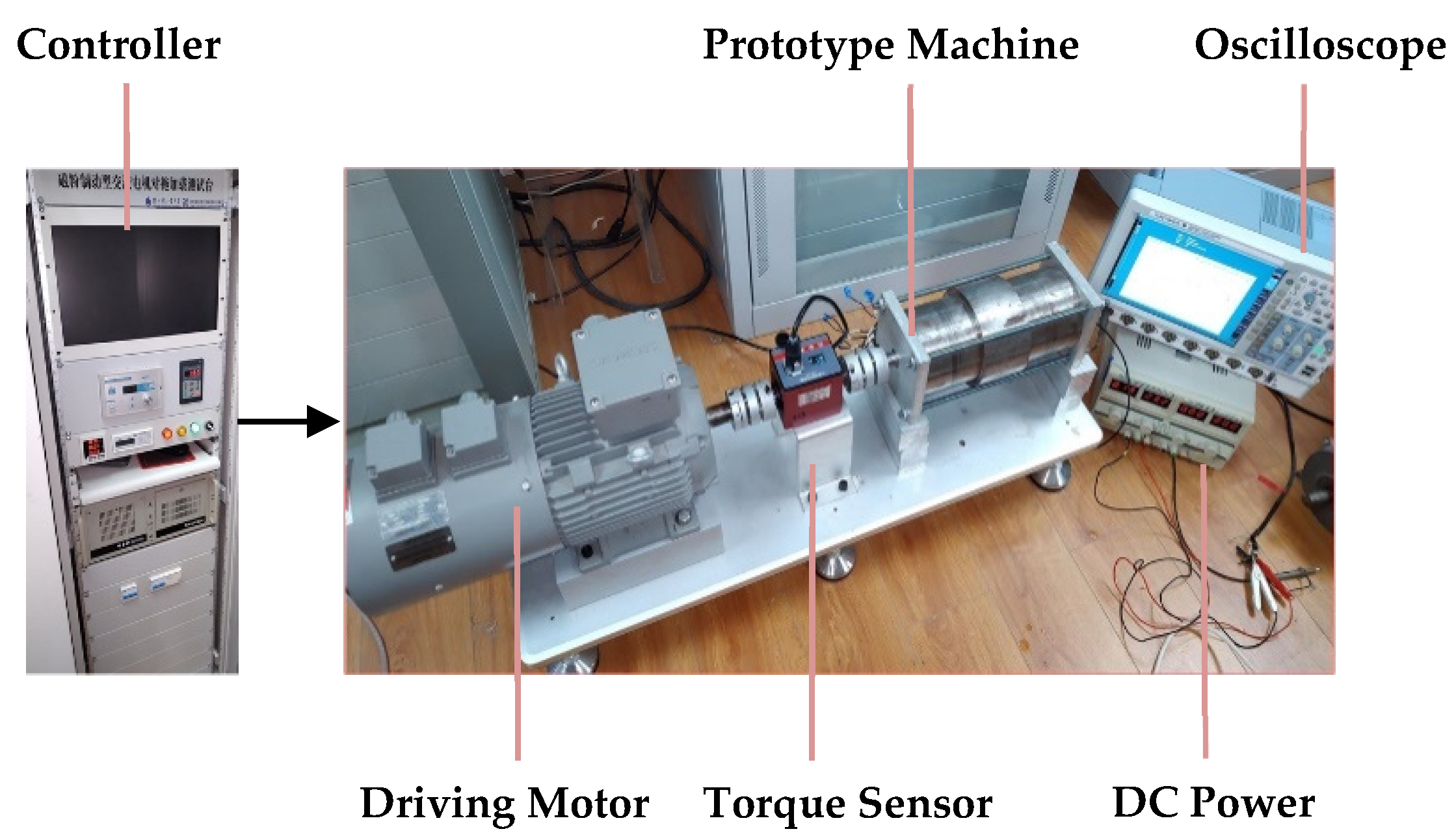
4.3. Experimental Verification

In this paper, the proposed analytical method for calculating cogging torque was verified by experiments, and a cogging torque measurement platform was built, as shown in Figure 9. In this platform, the prototype is a 24-slot/8-pole CPHES machine, and the specific parameters of the motor are shown in Table 1. The measuring range of the torque sensor is 300 mNm.
The measured cogging torque of the CPHES machine is compared with the FEM and analytical methods. The comparison outcomes are shown in Figure 10.
The experimental results and the cogging torque results obtained by the FEM and analytical methods are consistent in amplitude and frequency, which further verifies the effectiveness of the analytical method proposed in this paper.

5. Discussion

The cogging torque of the CPHES machine under different pole/slot combinations and structural parameters can be rapidly determined by the analytical method. For example, in Figure 11, when the rotor and magnetic pole structure remain unchanged, the effect of different slot numbers on the CPHES machine cogging torque can be quickly judged.
As shown in Figure 11a, the cogging torque of the 6-slot/2-pole motor is notably more significant than that of other motors with pole/slot combinations. Similarly, in Figure 11b,c, the cogging torque of the 36-solt/4-pole and 48-solt/8-pole motors is significantly lower than that of other motors with the same number of poles.

6. Conclusions and Further Research

Considering the limitations of the FEM in analyzing the cogging torque generated by the complex rotor poles and stator cogging structure of a CPHES machine, this paper proposes an accurate cogging torque calculation model for the CPHES machine. In this paper, four CPHES machines with different pole/slot combinations are used as examples, and the FEM and analytical method are used to calculate the cogging torque of the motor. The two calculation results are highly consistent, indicating that the cogging torque of the CPHES machine can be precisely obtained by using this calculation model. Because the calculation correctness of the FEM is very dependent on the model meshing, compared with the FEM, this method is far superior to FEM in terms of efficiency when the calculation accuracy is similar. Taking the 24-slot/8-pole CPHES machine as an example, about the time to calculate the cogging torque of one period, the proposed analytical method takes 0.45 s, and the 3D FEM takes 18 h. To further verify the practicability of the analytical method, this paper also built a cogging torque measurement platform for the CPHES machine. The measurement results are highly consistent with the calculation results of the analytical method.
In addition, this paper uses the analytical method to calculate the cogging torque of several common pole/slot combination CPHES machines. The analysis results show that under certain structural parameters, the cogging torque of a particular pole/slot combination motor is significantly lower than that of other pole/slot combinations, which provides an important theoretical basis for the cogging torque optimization and structural design of CPHES machines in the future. As a future extension of our work, this method will be applied to analyze cogging torque of CPHES machines with different PM shapes.

Author Contributions

Conceptualization, J.W.; methodology, J.W. and J.Y.; software, J.W. and M.Z.; validation, Z.Z. and C.Y.; formal analysis, J.W. and M.Z.; resources, Z.Z., M.Z. and J.W.; data curation, M.Z. and J.Y.; writing—original draft preparation, M.Z.; writing—review and editing, Z.Z. All authors have read and agreed to the published version of the manuscript.

Funding

This work was supported in part by the National Natural Science Foundation of China under Grant 52177063, and the Science and Technology key project in Henan Province under Grant 202102210019.

Institutional Review Board Statement

Not applicable.

Informed Consent Statement

Not applicable.

Data Availability Statement

Not applicable.

Conflicts of Interest

The authors declare no conflict of interest.

References

  1. Wu, J.; Yin, J. An Analytical Method of Calculating Back-EMF in Dual Consequent Hybrid Excitation Synchronous Machine. Chin. J. Electr. Eng. 2018, 4, 52–59. [Google Scholar]
  2. Wu, J.; Yin, J.; Zhuang, B.; Wang, M.; Zhang, J. Equivalent Magnetic Circuit Model for Consequent Pole Hybrid Excitation Synchronous Machine with AC Field Control. J. Magn. 2019, 24, 791–798. [Google Scholar] [CrossRef]
  3. Zhao, H.; Liu, C.; Song, Z.; Yu, J. Analytical Modeling and Comparison of Two Consequent-Pole Magnetic-Geared Machines for Hybrid Electric Vehicles. Energies 2019, 12, 1888. [Google Scholar] [CrossRef] [Green Version]
  4. Palomo, R.E.Q.; Gwozdziewicz, M. Effect of Demagnetization on a Consequent Pole IPM Synchronous Generator. Energies 2020, 13, 6371. [Google Scholar] [CrossRef]
  5. Zhou, M.; Zhang, X.X.; Zhao, W.X.; Ji, J.H.; Hu, J.N. Influence of Magnet Shape on the Cogging Torque of a Surface-mounted Permanent Magnet Motor. Chin. J. Electr. Eng. 2019, 5, 40–50. [Google Scholar] [CrossRef]
  6. Wang, K.; Gao, P.W.; Zhu, S.S.; Liu, C.; Jiang, R. Investigation of Cogging Torque and Torque Ripple in Consequent Pole Permanent Magnet. Proc. CSEE 2021. (In Chinese) [Google Scholar] [CrossRef]
  7. Fan, S. Research on Hybrid Permanent Magnet Field Modulation Motor. Ph.D. Thesis, Southeast University, Nanjing, China, 2019. [Google Scholar]
  8. Bernardeschi, C.; Dini, P.; Domenici, A.; Saponara, S. Co-simulation and Verification of a Non-linear Control System for Cogging Torque Reduction in Brushless Motors. In Proceedings of the International Conference on Software Engineering and Formal Methods, Oslo, Norway, 16–20 September 2019; Springer: Cham, Switzerland, 2019; Volume 12226, pp. 3–19. [Google Scholar]
  9. Dini, P.; Saponara, S. Design of an Observer-Based Architecture and Non-Linear Control Algorithm for Cogging Torque Reduction in Synchronous Motors. Energies 2020, 13, 2077. [Google Scholar] [CrossRef]
  10. Bu, F.; Yang, Z.; Gao, Y.; Pan, Z.; Pu, T.; Degano, M.; Gerada, C. Speed Ripple Reduction of Direct-Drive PMSM Servo System at Low-Speed Operation Using Virtual Cogging Torque Control Method. IEEE Trans. Ind. Electron. 2021, 68, 160–174. [Google Scholar] [CrossRef]
  11. Yang, Y.; Bianchi, N.; Bramerdorfer, G.; Zhang, C.; Zhang, S. Methods to Improve the Cogging Torque Robustness Under Manufacturing Tolerances for the Permanent Magnet Synchronous Machine. IEEE Trans. Energy Convers. 2021, 36, 2152–2162. [Google Scholar] [CrossRef]
  12. Simón-Sempere, V.; Simón-Gómez, A.; Burgos-Payán, M.; Cerquides-Bueno, J.-R. Optimisation of Magnet Shape for Cogging Torque Reduction in Axial-Flux Permanent-Magnet Motors. IEEE Trans. Energy Convers. 2021, 36, 2825–2838. [Google Scholar] [CrossRef]
  13. Li, Z.; Yu, X.; Wang, X.; Xing, X. Optimization and Analysis of Cogging Torque of Permanent Magnet Spherical Motor. IEEE Trans. Appl. Supercond. 2021, 31, 1–5. [Google Scholar] [CrossRef]
  14. Zienkiewicz, O.C.; Taylor, R.L.; Nithiarasu, P.; Zhu, J.Z. The Finite Element Method; Bathe and McGraw-Hill: London, UK, 2008. [Google Scholar]
  15. Tsukerman, I. Computational Electromagnetics: A Miscellany. J 2021, 4, 881–896. [Google Scholar] [CrossRef]
  16. Gajewski, M.D.; Miecznikowski, M. Assessment of the Suitability of Elastomeric Bearings Modeling Using the Hyperelasticity and the Finite Element Method. Materials 2021, 14, 7665. [Google Scholar] [CrossRef] [PubMed]
  17. Belytschko, T.; Liu, W.K.; Moran, B.; Elkhodary, K.B. Nonlinear Finite Elements for Continua and Structures, 2nd ed.; Wiley: Newark, NJ, USA, 2013; pp. 21–63. [Google Scholar]
  18. Demenko, A.; Sykulski, J.K. Analogies between Finite-Difference and Finite-Element Methods for Scalar and Vector Potential Formulations in Magnetic Field Calculations. IEEE Trans. Magn. 2016, 52, 1–6. [Google Scholar] [CrossRef]
  19. Nguyen-Thoi, T.; Liu, G.R.; Lam, K.Y.; Zhang, G.Y. A face-based smoothed finite element method (FS-FEM) for 3D linear and geometrically non-linear solid mechanics problems using 4-node tetrahedral elements. Int. J. Numer. Methods Eng. 2009, 78, 324–353. [Google Scholar] [CrossRef]
  20. Jin, J.M. Theory and Computation of Electromagnetic Fields, 1st ed.; Wiley-IEEE Press: Newark, NJ, USA, 2011; pp. 297–330. [Google Scholar]
  21. Atia, K.S.R.; Heikal, A.M.; Obayya, S.S.A. Matrix-Free Time Domain Gradient Smoothing Method with Stretched-Coordinates Perfectly Matched Layer for Analysis of Photonic Devices. J. Lightw. Technol. 2020, 38, 5791–5800. [Google Scholar] [CrossRef]
  22. Zeng, W.; Liu, G.R. Smoothed Finite Element Methods (S-FEM): An Overview and Recent Developments. Arch. Comput. Methods Eng. 2016, 25, 397–435. [Google Scholar] [CrossRef]
  23. Wan, D.; Hu, D.; Yang, G.; Long, T. A fully smoothed finite element method for analysis of axisymmetric problems. Eng. Anal. Bound. Elem. 2016, 72, 78–88. [Google Scholar] [CrossRef]
  24. Jin, J.M. The Finite Element Method in Electromagnetics, 3rd ed.; Wiley: Newark, NJ, USA, 2015; pp. 19–40. [Google Scholar]
  25. Marechal, Y.; Ramdane, B.; Botelho, D.P. Computational Performances of Natural Element and Finite Element Methods. IEEE Trans. Magn. 2014, 50, 405–408. [Google Scholar] [CrossRef]
  26. Ming, T.W.Z.; Zhou, M. Adaptive Finite Element Analysis in the Application of Electromagnetic Mechanics. In Proceedings of the Eighth International Conference on Computational Intelligence and Security, Guangzhou, China, 17–18 November 2012; pp. 687–689. [Google Scholar]
  27. Xu, W.; Wang, G.; Duan, N.; Wang, S.; Guo, Y.; Zhu, J. Extended Finite-Element Method for Weak Discontinuities in Electric Fields. IEEE Trans. Appl. Supercond. 2016, 26, 1–5. [Google Scholar] [CrossRef]
  28. Wang, G.; Wang, S.; Duan, N.; Huangfu, Y.; Zhang, H.; Xu, W.; Qiu, J. Extended Finite-Element Method for Electric Field Analysis of Insulating Plate with Crack. IEEE Trans. Magn. 2015, 51, 1–4. [Google Scholar]
Figure 1. Structure of CPHES machine.
Energies 15 00878 g001
Figure 2. Spatial phasor diagrams of MMFs in HEMs. (a) Demagnetization in traditional HEMs; (b) Magnetization in traditional HEMs; (c) Demagnetization in CPHES machine; (d) magnetization in CPHES machine.
Energies 15 00878 g002
Figure 3. The air-gap flux distribution in a 6-slot/2-pole CPHES machine.
Energies 15 00878 g003
Figure 4. The flux Φall and Φpm in a period of cogging torque.
Energies 15 00878 g004
Figure 5. Rotor space position.
Energies 15 00878 g005
Figure 6. Calculation process.
Energies 15 00878 g006
Figure 7. Air gap permeance model.
Energies 15 00878 g007
Figure 8. Cogging torque calculation results of CPHES machine: (a) 24-slo t/2-pole; (b) 24-slot/4-pole; (c) 24-slot/8-pole; (d) 24-slot/16-pole.
Energies 15 00878 g008aEnergies 15 00878 g008b
Figure 9. Cogging torque measurement platform.
Energies 15 00878 g009
Figure 10. Comparison of experimental results.
Energies 15 00878 g010
Figure 11. Cogging torque calculation results for the different number of slots. (a) 2-pole; (b) 4-pole; (c) 8-pole motors.
Energies 15 00878 g011
Table 1. The main parameters of the four models.
ParameterValueParameterValue
Outer diameter of stator core [mm]61Stator core length [mm]85
Stator core inner diameter [mm]34.5Rotor core outer diameter [mm]30
Stator yoke thickness [mm]4Rotor core inner diameter [mm]12
Stator tooth width [mm]4.606Rotor yoke thickness [mm]18
Air gap length [mm]2Axial length of yoke [mm]290
PM thickness [mm]2.5Axial length of rotor shaft [mm]60
Pole-arc coefficient0.85Axial length of rotor [mm]85
Axial length of PM [mm]85Axial length of iron pole [mm]85
Publisher’s Note: MDPI stays neutral with regard to jurisdictional claims in published maps and institutional affiliations.

