1. Introduction
Issues of high-temperature recuperation have an attitude to the processes of transferring of substance and energy, which are complicated by the simultaneous action of various factors. These are and different kinds and regimes of substance motion, and different mechanisms of transferring heat in the objects that are investigated. Many works are devoted to studying complicated heat transfers in compact high-temperature heat exchangers of various types [
1,
2,
3,
4]. The dominant mechanisms of transferring in them are convective and radiative heat transfer [
5,
6,
7,
8,
9,
10]. The feature of the work consists of the applied nature of the research aimed at studying the conditions of flow and heat transfer in an air-cooled duct, which is the basis of heat recuperation devices for high-temperature industrial plants. The formulation of the research tasks most fully describes the conditions-temperature, magnitude and direction of the heat flow density, the type of coolant and its mass flow, the geometry of the duct and the main physical and mechanical characteristics of its surfaces observed in modern high-temperature processes for the production of glass and stone fibers. The research and processing of the results were carried out using classical methods [
11,
12]. At the same time, for each of the duct surfaces involved in heat transfer and differing in the magnitude and direction of the supplied heat flow, Nusselt numbers and temperature pressures are determined. The results of the research were compared with the case of convective heat transfer in pipes and ducts with symmetrical heat supply to the duct surfaces, which allowed us to establish the nature and magnitude of the influence of complicated heat transfer on the characteristics of the process, in order to obtain their qualitative and quantitative indicators. The generalized dependences obtained make it possible to calculate the aerodynamic drag, temperature and energy parameters of the process, with complicated heat transfer and mixed motion necessary for the design of high-temperature heat recuperation systems in order to increase the energy efficiency of production processes. Utilization and reduction of heat losses in high-temperature industrial plants in order to increase their energy efficiency is implemented on the basis of the use of innovative heat exchange devices or heat recuperation systems. Heat transfer processes in them are carried out at high temperature heads, one-sided heat input, complicated radiation-conductive-convective heat transfer and mixed motion of air as a heat carrier.
Problem definition.
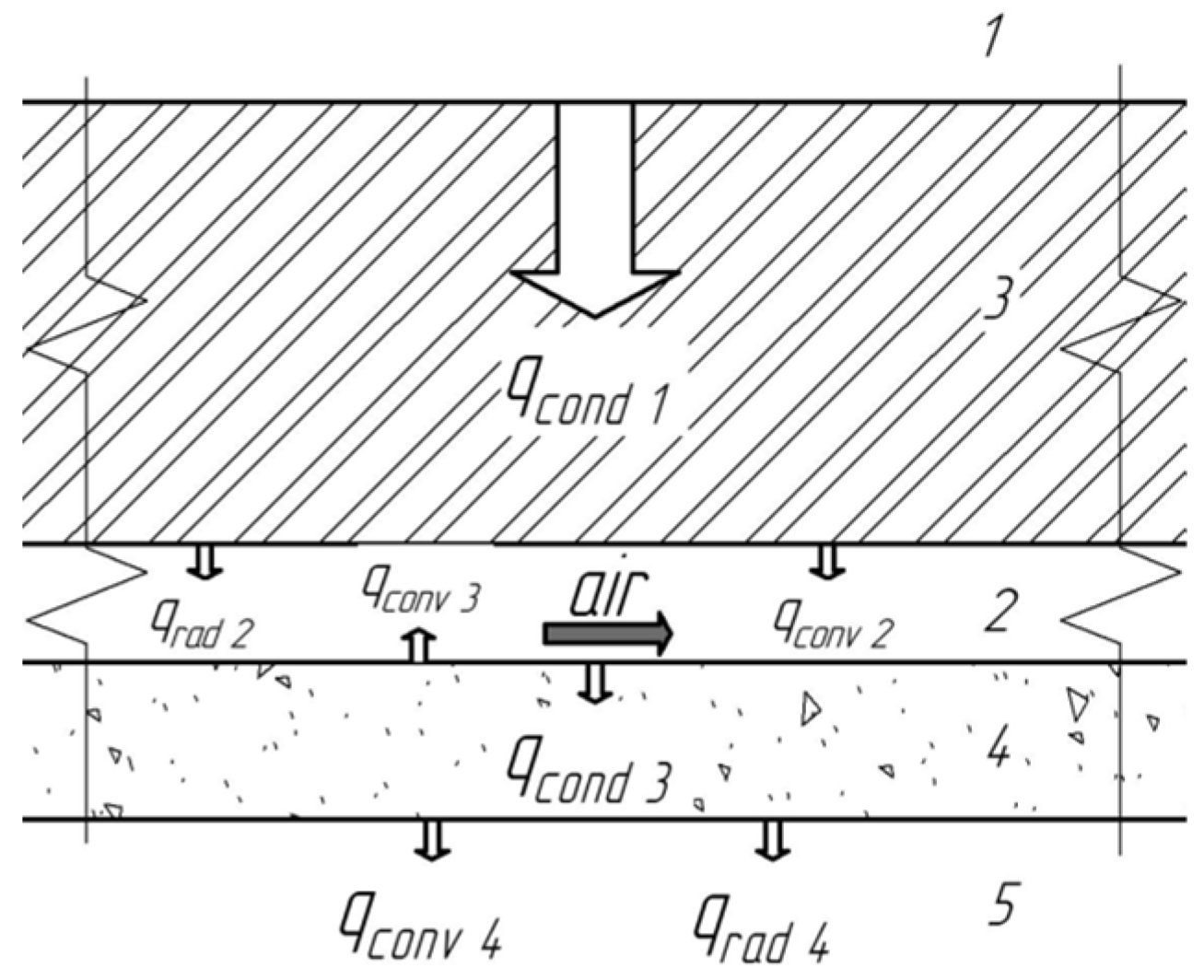
The simplified scheme of heat flow densities for a fragment of the lining is shown, which is typical for high-temperature heat recuperation systems with an air heat curtain,
Figure 1.
In the summary conductive heat flow through the lining
, one consists of losses with convective
and radiation
heat flows from the internal surface of the air duct
; the radiation heat flow
makes up for convective heat transfer from the surface of the duct
and heat loss by conductive
through thermal insulation
. The heat losses through thermal insulation
consists from convective
and radiation
heat flows from external surface of the equipment to environment. As can be seen, the heat losses to the environment comprise complicated radiation-convective heat transfer. For an integral description of all heat flows, the classical expressions presented in [
13,
14,
15,
16] are used to calculate the value of the convective and radiation heat exchange coefficients. It is assumed that each of the heat transfer mechanisms is independent, and there is no interaction between them.
3. Physical Model of Complicated Heat Transfer and Mixed Air Motion in the Flat Duct
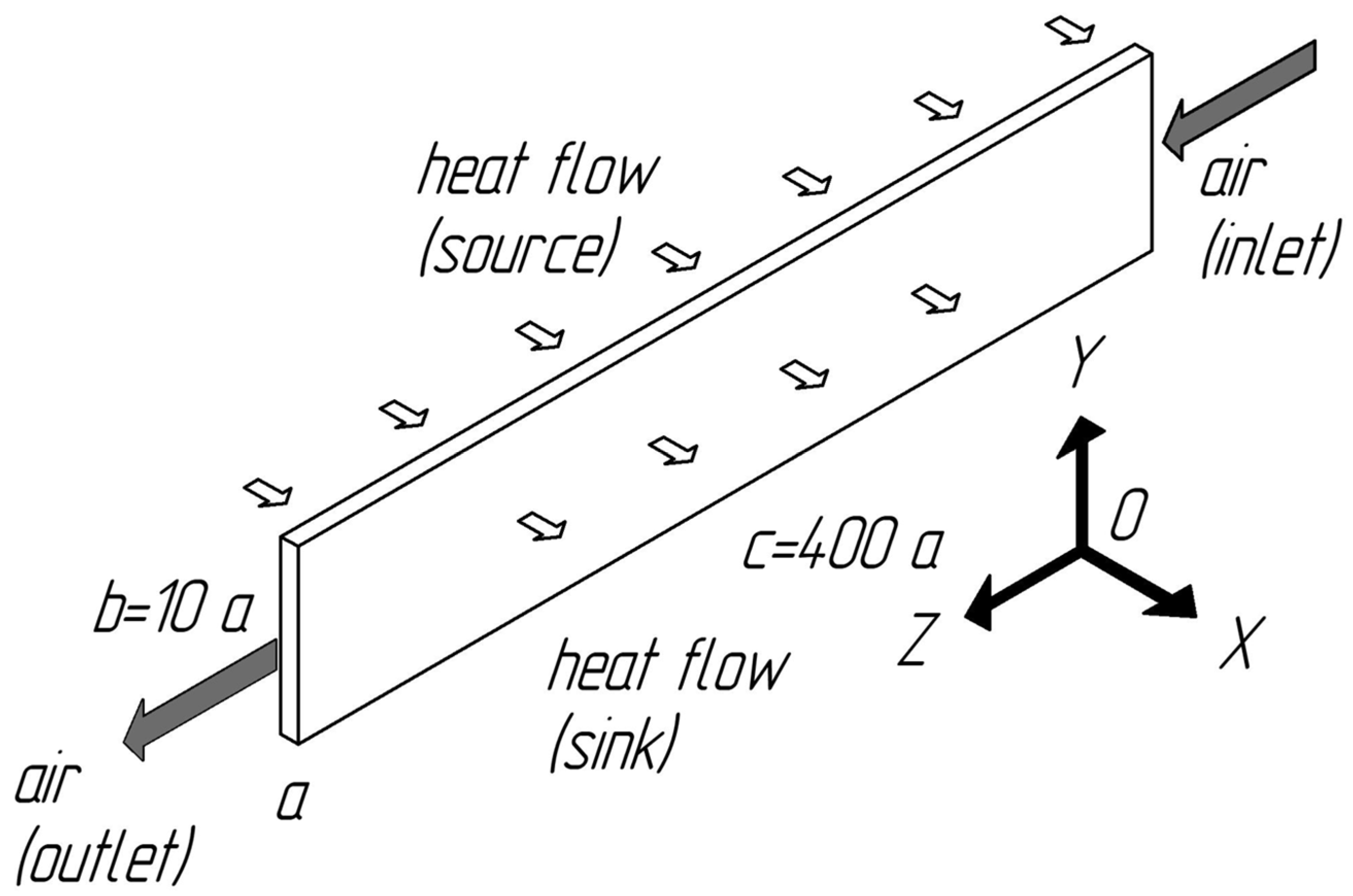
Features of the problem are: (a) one-sided heat input, as a result of which traditional convective heat transfer in the duct is complicated by radiation heat transfer between the hot surface (source) and other surfaces of the duct that are not heated; (b) air is considered as a diathermal medium; and (c) multidirectional action of vectors of volume forces and pressure forces. The research is conducted using a CFD package for turbulent flow. In particular, to describe radiation heat transfer in the duct, the surface-to-surface (S2S) model of radiation heat transfer in space bounded by gray diffuse surfaces is used. The main assumption in the S2S model-absorption, radiation or scattering by a gas medium-is ignored, and only surface radiation is considered in the analysis. A non-isothermal flow is modeled, turbulent flow regime is considered, the air flow is taken as a Newtonian liquid and the dependence of the thermophysical properties of air on temperature is considered.
Mathematical model of flow and complicated heat transfer in the duct with mixed motion of air. In a general view, the expressions for the S2S model are written as follows [
15,
16]
energy flow transmitted by other surfaces—;
mathematical formulation of the principle of reciprocity—;
heat flow that is gotten on the surface from surfaces ;
factor of mutual influence
between the two surfaces with final sizes
and
—
radiation energy flow that transfers from surface
where
—area of the surface
;
—factor which consider geometrical features position of the surfaces
and
and influence on the part of the energy that transmitted from surface
to surface
;
—heat flow that get in the surface
from environmental;
—defines the visibility
to
(
if
is visible from
or 0 otherwise);
—radiant emittance of the surface
;
—radiant reflectance of the surface
;
—Stefan-Boltzmann constant. Indexes:
—indexes refer to data that get in or get out, correspondingly;
to refer to the surfaces
, correspondingly.
In convective heat transfer, the equations of continuity, momentum transfer, energy, kinetic energy dissipation and kinetic energy dissipation rate were used.
The following boundary conditions were set
where
W/m
2,
kg/h,
°C, c = 13.0 m—the parameters of the pilot plant; radiant emittance of duct surfaces
.
4. Data Processing and Displaying Technique
Results of the research are viewed as integral characteristics, namely: average heat exchange coefficient from the duct surface in the i section ; average heat flow density at the wall of the duct ; average temperature of the wall of the duct ; average mass air temperature ; average mass air flow rate ; average integral heat exchange coefficient over the length of the duct ; average integral temperature head ; average integral temperature of air dimensionless average integral temperature head ; Nusselt average number ; pressure losses in the duct caused by friction, Darcy-Weisbach formula, ; average coefficient of friction resistance and Nusselt local number , where —linear dimensions of the duct, respectively: width, height and length; —local heat flow density on the wall in the i section, is determined by the numerical experiment; —temperature of air, is determined by the numerical experiment; —local temperature of the wall in the i section, is determined by the numerical experiment; —air velocity, is determined by the numerical experiment; —coordinates along the axes, respectively, OX, OY, OZ; —characteristic linear duct size; —average heat exchange coefficient from the duct surface; —the coefficient of thermal conductivity and density, respectively, depend on the air temperature; —average tangential stress on the duct wall is determined by the experiment for the hot surface and the unheated surface. Indexes: —value is determined for the air flow; and —value is determined for the duct wall.
For the analysis of the obtained results of a numerical experiment and the convenience of comparing them with the known results of convective heat exchange in pipes under turbulent flow [
19,
20,
21,
22], the data are presented in a criterion form. The thermophysical properties that are part of dimensionless complexes are determined for the average mass temperature of the flow in this section. The hydraulic diameter is used as the characteristic linear size of the duct cross-section. The effect of free and forced convection on the heat transfer intensity is determined from the Rayleigh (
) and Peckle (
) complexes, respectively. The intensity of heat transfer in the dimensionless view is presented by Nusselt number.
Generalization of the results of the numerical research was carried out by: dimensionless local coordinate—; average dimensionless coordinate ; average Reynolds integral number along the length of the calculated region ; reduced heat transfer intensity from the hot surface ; dimensionless temperature head from the hot surface ; dimensionless temperature head from the unheated surface ; average coefficient of friction resistance, where is: —local Reynolds number based on the results of a numerical experiment; —the average Prandtl integral number along the length of the calculated region, determined by analogy with the number . Indexes: 1, 2—the value refers to the hot surface and the non-heated surface, respectively.
Verification of the adequacy of the mathematical model is carried out according to the test research, in which the intensity of convective heat transfer is determined for the described duct geometry under turbulent flow, double-sided heat input and boundary conditions of the 2nd kind. Radiation heat transfer in the duct is not considered. Other characteristics of the test research model correspond to the values taken for the main research. The heat flux density for double-sided heat input is chosen by the condition—, where is the heat flux density for double-sided heat input (main research).
The results of the test research are presented in a generalized form in the
coordinate system and compared with the existing results of the research of convective heat transfer in pipes with turbulent flow at small heat flow densities, when there is still no effect on heat transfer of non-isothermicity through natural convection and there is no change in the thermophysical properties of the heat carrying agent [
22]
where is
,
.
The coefficient of hydraulic friction resistance is calculated as follows:
Limits of application of expression (1):
;
[
22]. The discrepancy between the experimental data and the results of calculations using expression (1) does not exceed 8%.
5. Results of Research Aerodynamics and Heat Transfer for One-Sided Heat Input
The initial data and algorithm for performing a numerical experiment are selected from real experiments of testing a pilot plant, and are shown in
Table 1.
The designations of experiments are given in
Table 1, and are used as captions in the figures (
Figure 3,
Figure 4,
Figure 5,
Figure 6,
Figure 7,
Figure 8,
Figure 9,
Figure 10,
Figure 11,
Figure 12,
Figure 13,
Figure 14,
Figure 15,
Figure 16,
Figure 17 and
Figure 18).
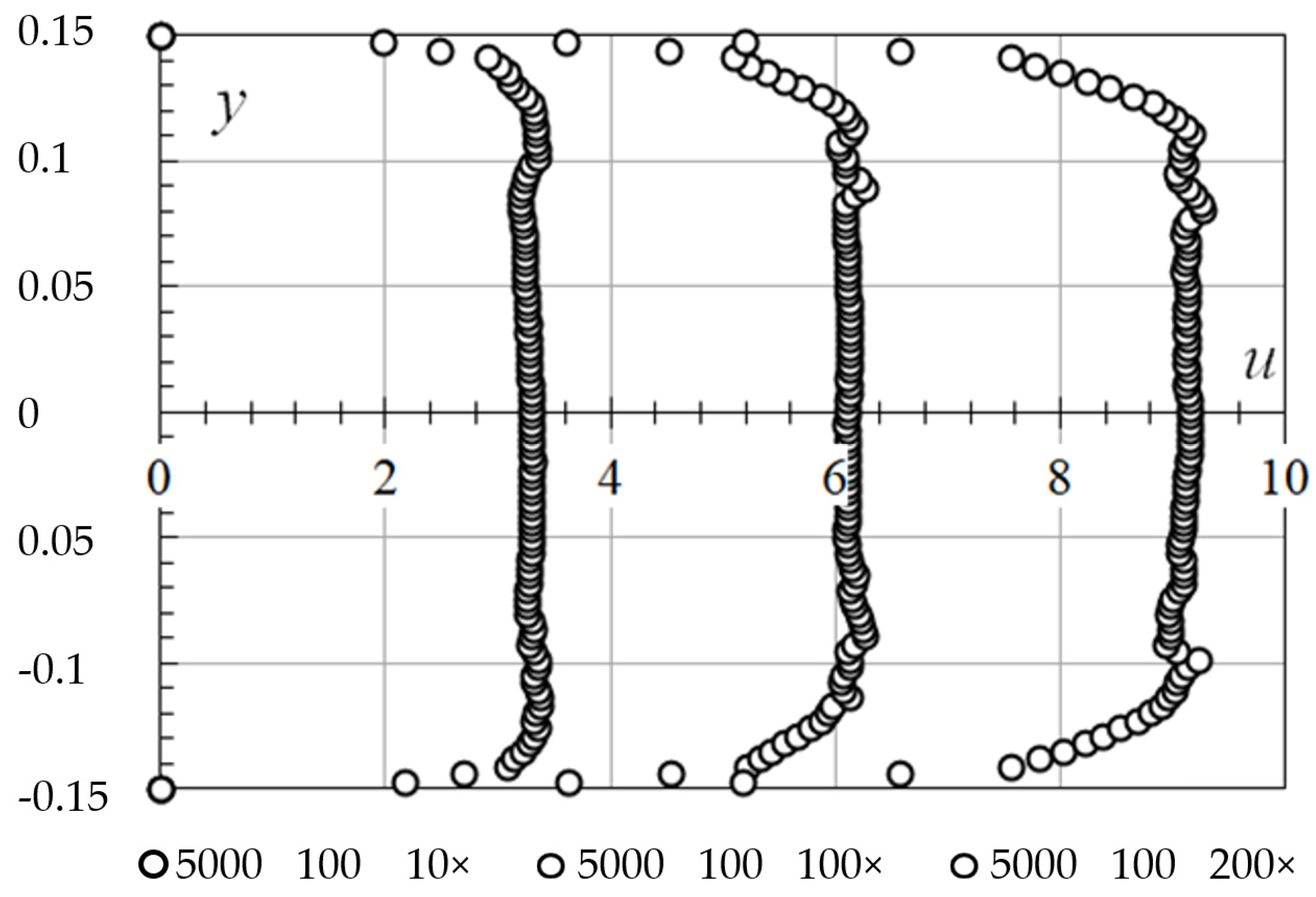
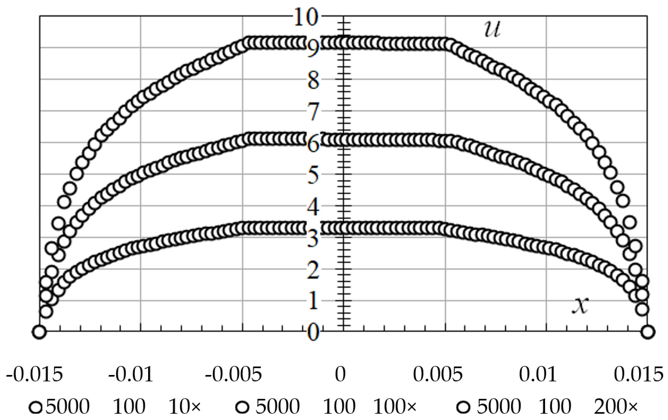
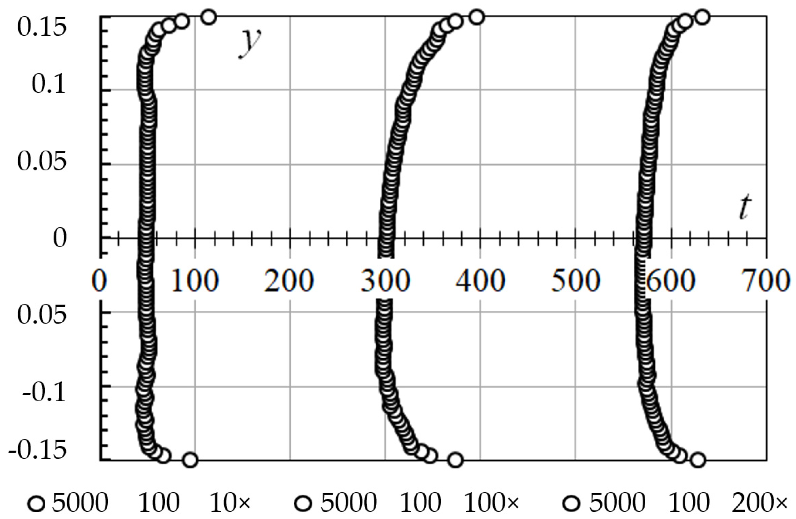
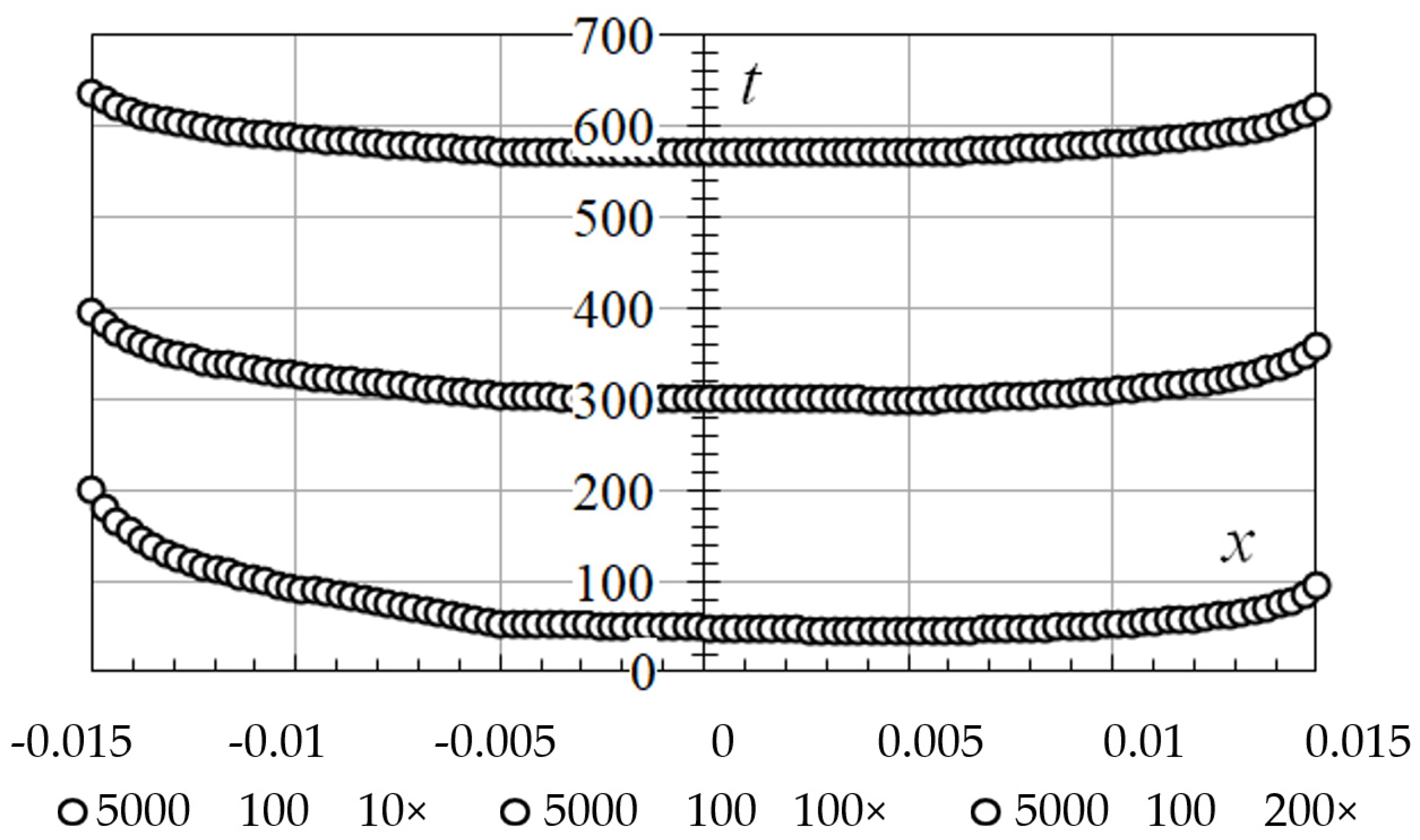
Figure 3,
Figure 4,
Figure 5 and
Figure 6 show the velocity and temperature distributions in the air flow, in the vertical ZOY and horizontal ZOX central-section of the duct. The profiles are constructed for cross-sections located at a distance of 10, 100 and 200 calibers from the entry plane. As the caliber, the value of the hydraulic diameter of the duct
X is taken.
For the results obtained for the mass flow rates of air of 100, 150 and 200 kg/h, an asymmetry of the temperature profiles relative to the central axes (cross-sections) of the duct symmetry is observed. The influence of free convection in the central part of the duct on vertical temperature profiles (
Figure 5) is observed—the profiles are more filled than in the lower part, below the plane of symmetry. It is observed a higher temperature at the end of duct with a lower air flow rate, than with a higher air flow rate. It is observed decreasing the temperature difference between the duct surfaces as the air temperature increases. The surface temperature of the source (with one-sided heat input) is higher than the temperature of the non-heated surface along the entire length of the duct (
Figure 6). Along the perimeter of the duct cross-section, its surface temperature does not have the same value, just as local heat exchange coefficients differ along the duct perimeter. Processing of the results of the research consisted in determining local, average heat exchange coefficients over the duct cross-section. At the same time, considered that the average duct surface temperatures have different values, the heat exchange coefficients are determined separately for the hot surface and the non-heated surface. In
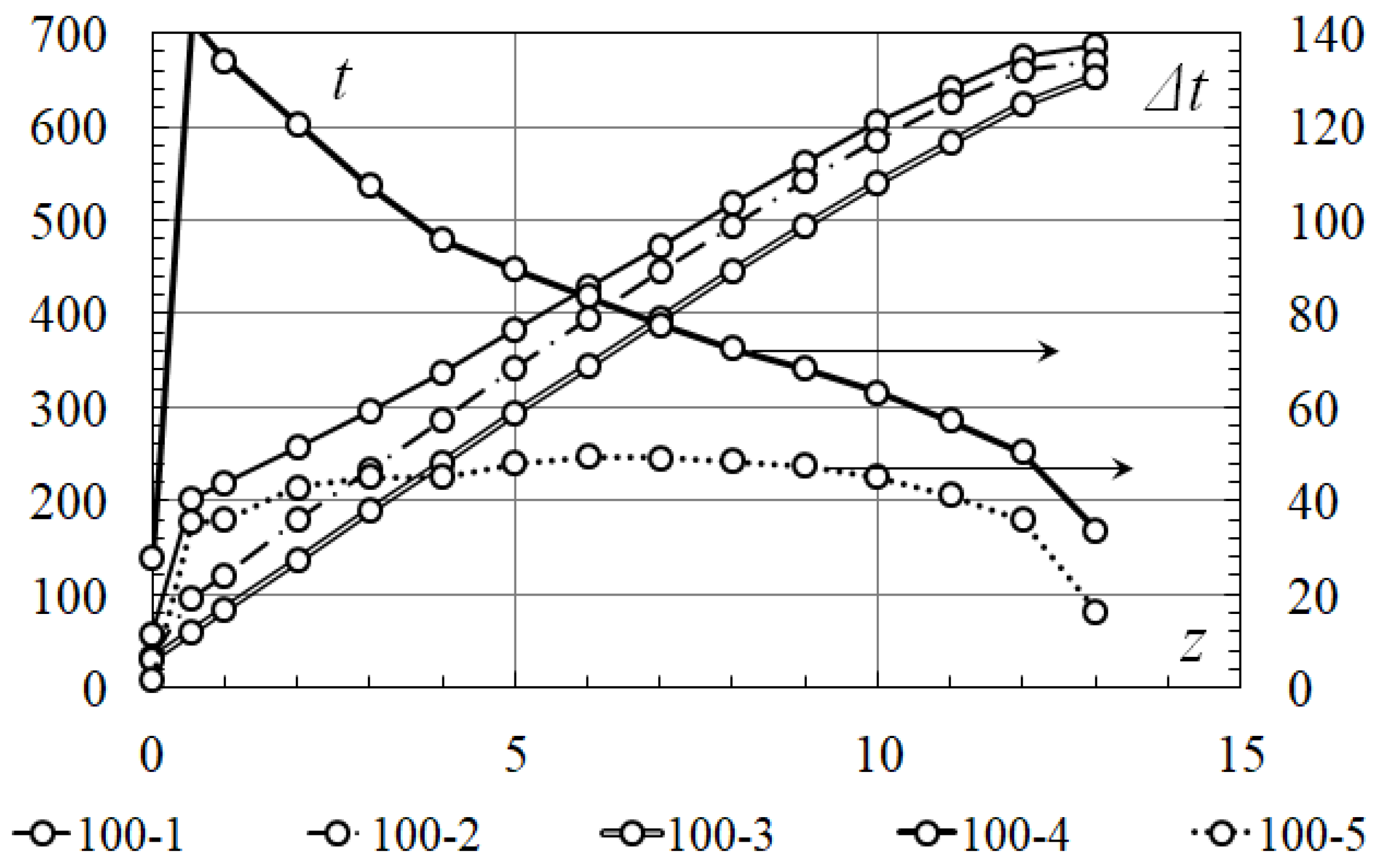
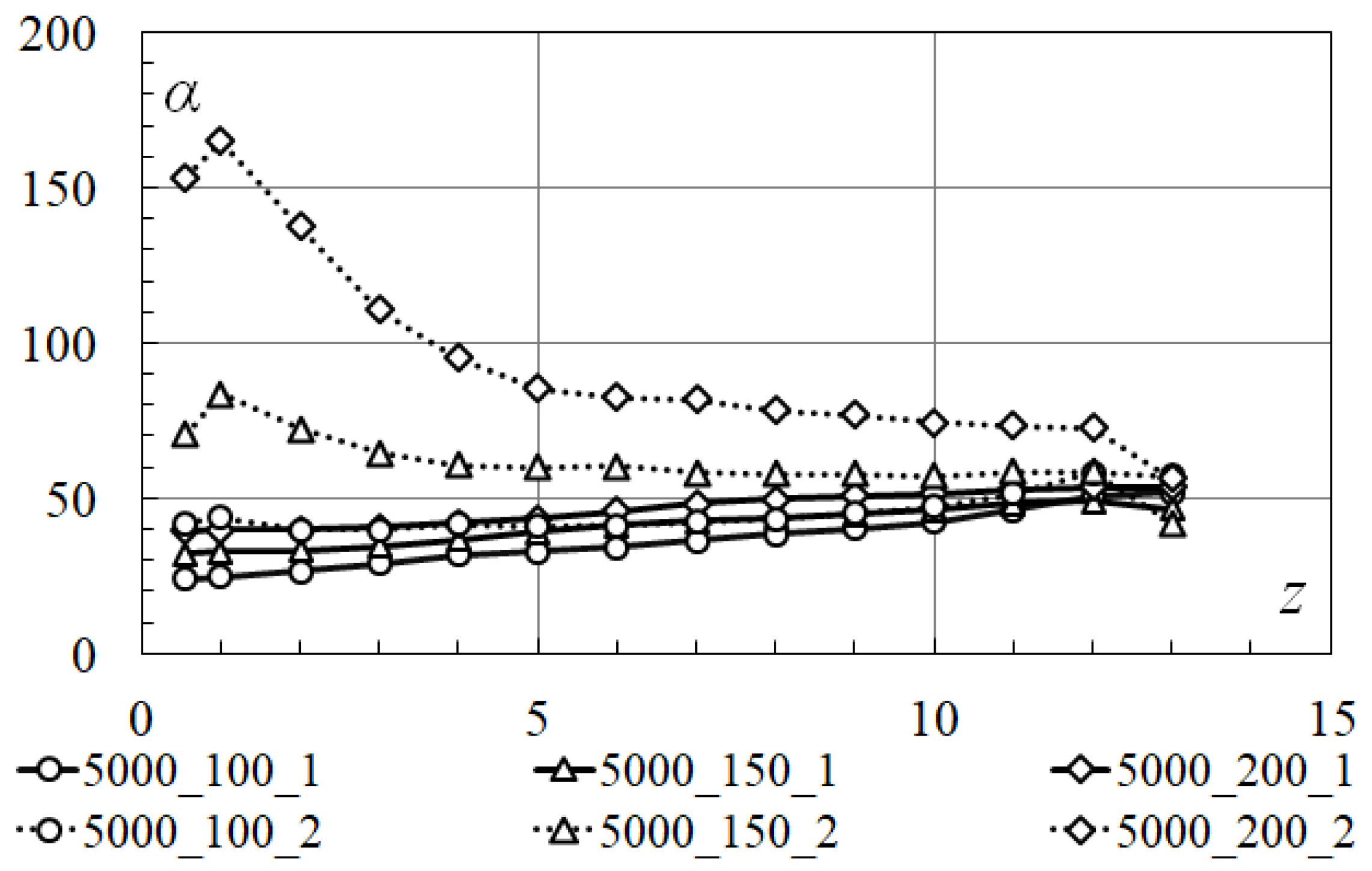
Figure 7 shows graphs of changes in the average temperatures (main axis on the left) of the hot surface and the non-heated surface and air along the length of the duct. In addition, this figure shows the temperature heads (auxiliary axis on the right) to the hot surface and the non-heated surface along the length of the duct.
The qualitative valuation, which is obtained for one-sided heat input at W/m2, is also observed for cases of heat transfer at and 6000 W/m2.
It is the lower the mass flow rate of air, than is the higher the overall temperature level of the process: (a) higher temperatures of the surfaces of the duct; (b) higher air temperature at the outlet of the duct; (c) smaller temperature difference between the hot surface and the non-heated surface at the outlet of the duct; and (d) smaller difference in temperature heads on the hot surface and on the non-heated surface. It should be expected that at the lower mass flow rate of air, at the end of the duct, the heat transfer rate on the hot surface of the duct and on the non-heated surface will approach a certain equal value. The different pattern of change in the value of the temperature head along the length of the duct on its hot surface and the non-heated surface indicates a qualitative difference in the heat transfer processes on these surfaces. It should also expect different patterns of changes in local heat exchange coefficients on these surfaces along the length of the duct. The distribution of the heat flow density along the length of the duct on the hot surface and the non-heated surface for different conditions of the experiment is shown in
Figure 8. The results obtained have well-defined sections with a non-monotonous change in the value of the heat flow density—sections at the inlet/outlet of the duct. The non-monotonicity of the
value at the beginning of the duct-
-is due to the influence of the initial hydrodynamic and thermal regions, as well as the conditions for formulating a numerical experiment. The non-monotonicity of
at the end of the duct-
-is due only to the conditions of the numerical experiment. When processing the results of the research, empirical correlations are approximated by power dependences of the species-
(approximation reliability
). When constructing approximation dependencies, the plots
and
are excluded from consideration. Further processing of the research results is carried out using approximation dependencies.
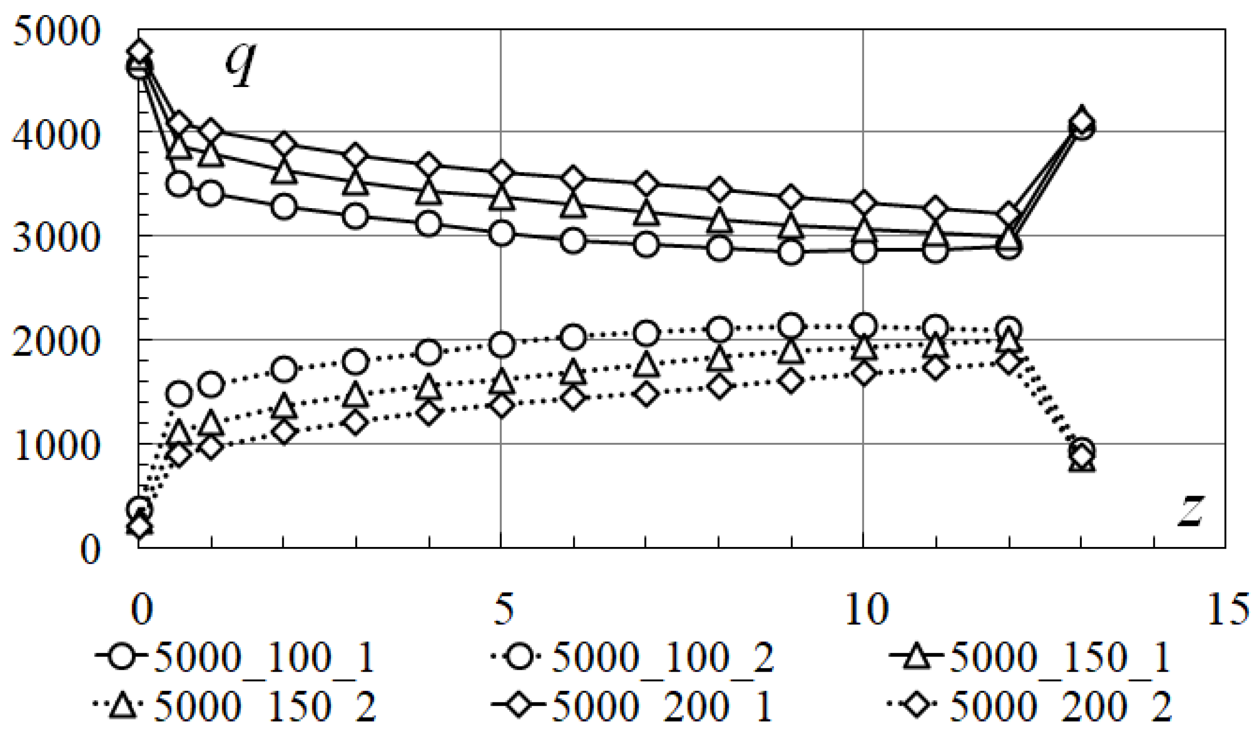
In
Figure 9 shows the results of calculating local heat exchange coefficients (
) along the duct length (
), on the hot surface of the duct and on the non-heated surface of the duct. The present results demonstrate that: (a) the behavior of changes in heat exchange coefficients is different, if for the hot surface it qualitatively approaches the process of forced convection, then for the non-heated surface, such an analogy is not observed; (b) the heat exchange coefficients on the non-heated surface are greater than the heat exchange coefficients on the hot surface; and (c) as the air heats up, the difference between the heat exchange coefficients on opposite duct surfaces decreases.
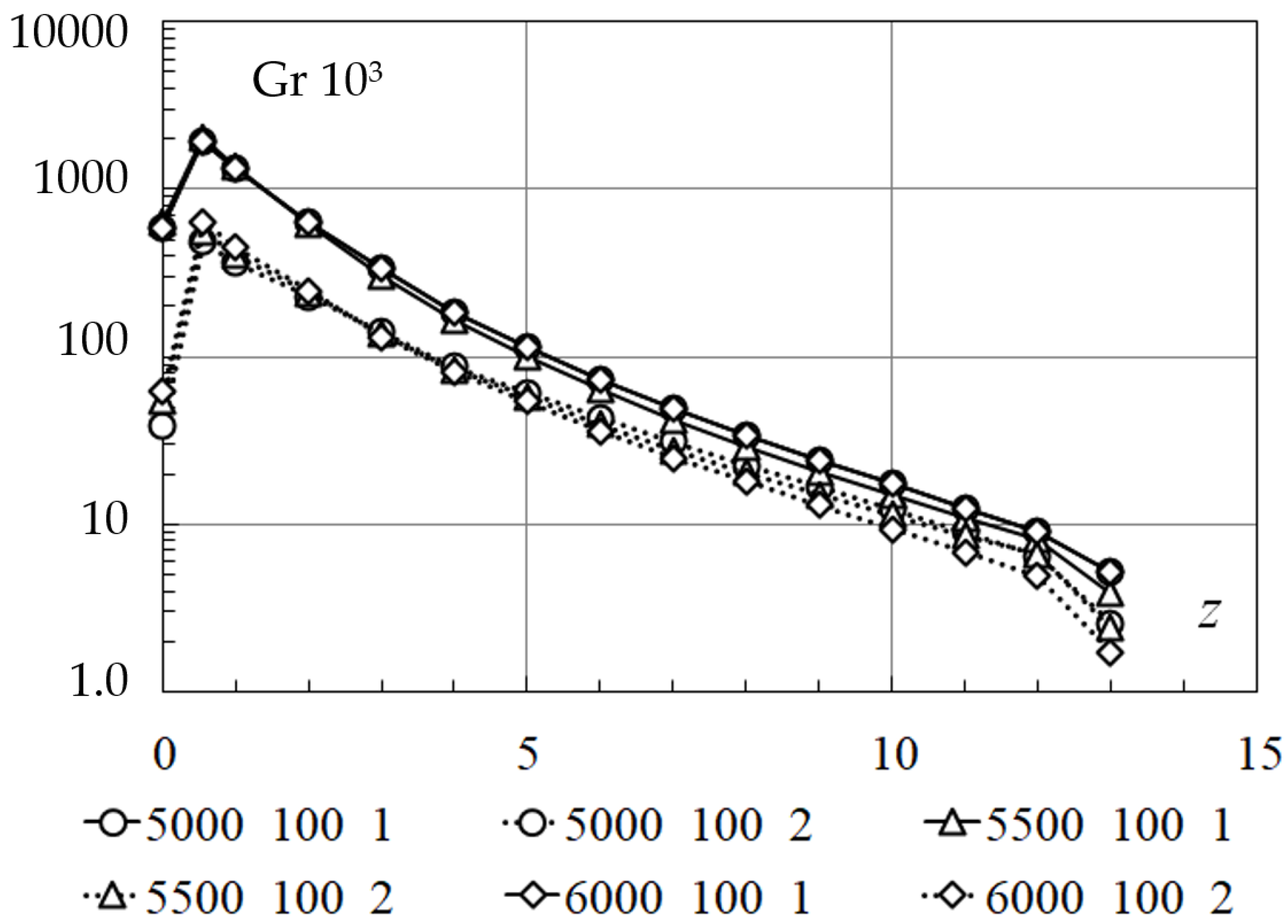
Further generalization of the research results is carried out in the form of dimensionless complexes. Evaluation of the influence of gravitational and inertial forces on the intensity of heat transfer in the duct begins with determining the value of the Grashof
and Reynolds
numbers along the length of the duct. As noted above, the thermophysical properties that make up dimensionless complexes are determined for the average mass temperature of the flow. The behavior of the Grashof numbers along the length of the duct, on the hot surface of the duct and on the non-heated surface for different regimes of the experiment is shown in
Figure 10. The behavior of the Grashof numbers remains the same for all cases provided for in the experiment plan (
Table 1). By analogy with the Grashof number, dependencies are also obtained for Reynolds number. The Reynolds numbers dynamics is shown in
Figure 11, and is similar for all experiments performed.
The greatest influence of gravitational forces on the heat transfer intensity is observed in one-third of the duct (). At the hot surface, the effect of gravitational forces is 1.5–4.0 times higher than at the non-heated surface. The absolute values of the Grashof numbers allow us to assume about the undisputed effect of free convection on the intensity of convective heat transfer in the duct and about the expected differences in the values of heat exchange coefficients for mixed convection from their values for purely forced convection. Absolute values and the behavior of changes in Reynolds numbers indicate a developed turbulent flow regime along the entire length of the duct. The Reynolds number weakly depends on the value of the heat flux density on the hot surface. The difference in local values of the Reynolds numbers increases along the length of the duct, but does not exceed 8% of the initial value.
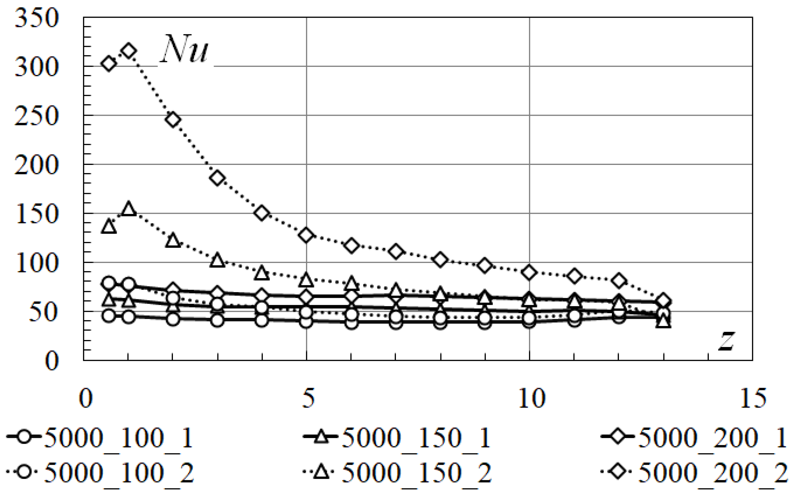
The dependence of the local Nusselt numbers along the length of the duct on the hot surface and on the non-heated surface is shown in
Figure 12. The summary graph of the results of the research of complicated heat transfer in one-sided heat input and mixed motion of air is presented in
Figure 13. The results are presented as the dependence of the local Nusselt numbers on the value of the dimensionless coordinate
Z, which is determined by the expression
.
The intensity of convective heat transfer on the hot surface is less than the intensity of ones on the non-heated surface. The intensity of convective heat transfer on the hot surface is more affected by the mass flow rate of air in the duct than by the value of the heat flow density on the surface. On the summary graph
Figure 13, it can be seen that the local Nusselt numbers on the hot surface for different values of the
value almost coincide. With sufficient accuracy for technical calculations, it can be argued that in the range of values
W/m
2, the intensities of convective heat transfer are the same. For the non-heated surface, the local Nusselt numbers depend on both the mass flow rate of air in the duct and the value of the heat flow density. In this case, the dependence from the heat flow density
is more significant than for the hot surface. As the
value increases, the local Nusselt number curves on the non-heated surface approach similar curves on a hot surface. As the
coordinate decreases, the difference in the values of local Nusselt numbers decreases for different heat flow densities
and different air mass flows in duct
.
Before plotting generalizing dependences of the average Nusselt numbers () as functions on the dimensionless coordinate (), it is verificated the mathematical model and calculation methods used on the traditional problem of convective heat transfer in the duct with symmetric two-sided heat input.
The research of aerodynamics and heat transfer in symmetric two-sided heat input and turbulent flow regime in the duct (
Table 2) has the following goals:
- -
verification of the mathematical model and computational methods;
- -
comparison of the results of the research with existing solutions for convective heat transfer in pipes and ducts;
- -
comparison and generalization of the results of the research of flow and heat transfer in the duct under turbulent flow regime and symmetric two-sided heat input with the results of the research of one-sided heat input, complicated heat transfer and mixed motion.
The following boundary conditions were set
where is
W/m
2;
kg/h;
°C; c = 13.0 m.
The results of the test computational experiment are presented in a dimensionless form. They are compared with the results of the computational experiment on the complicated heat transfer and mixed motion of air (
Figure 14,
Figure 15 and
Figure 16).
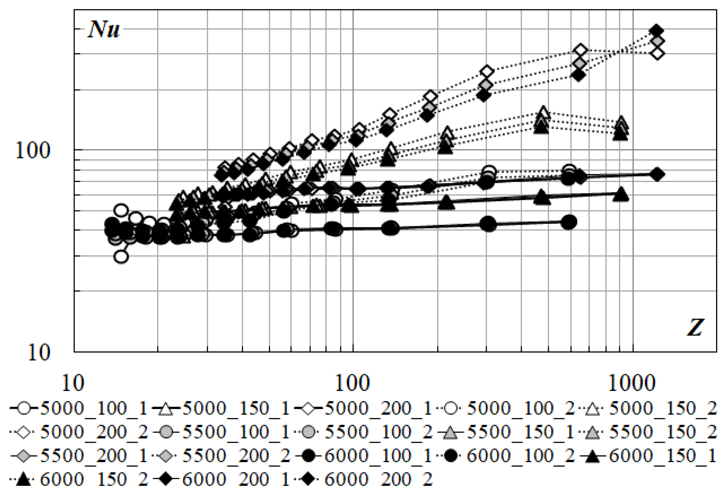
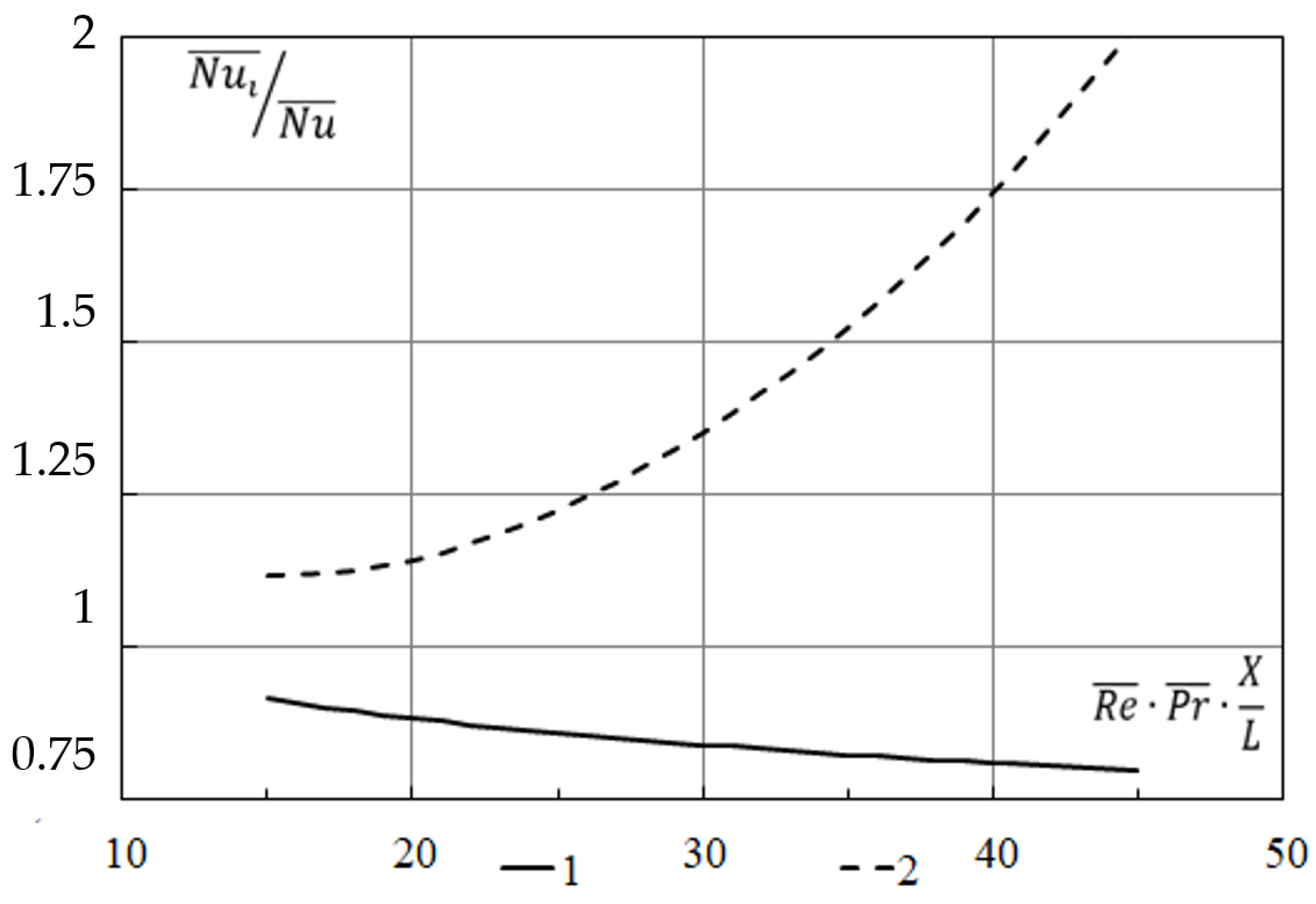
Figure 14 shows local Nusselt numbers on the hot surface, the non-heated surface and surfaces with symmetric two-sided heat input, respectively.
Figure 15 shows the reduced Nusselt numbers on the hot surface and the non-heated surface, respectively.
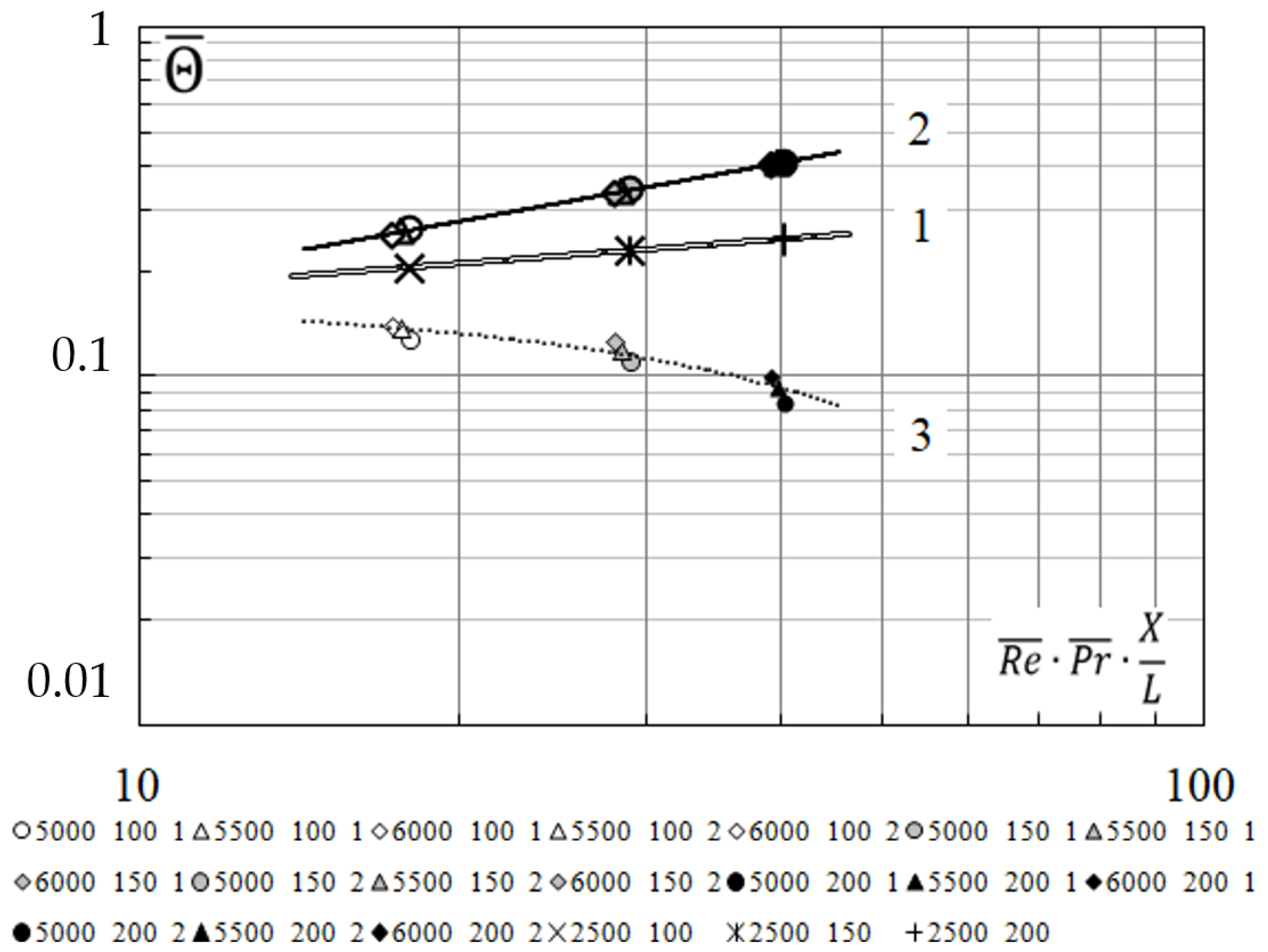
Figure 16 shows dimensionless average integral temperature heads for the three cases described above.
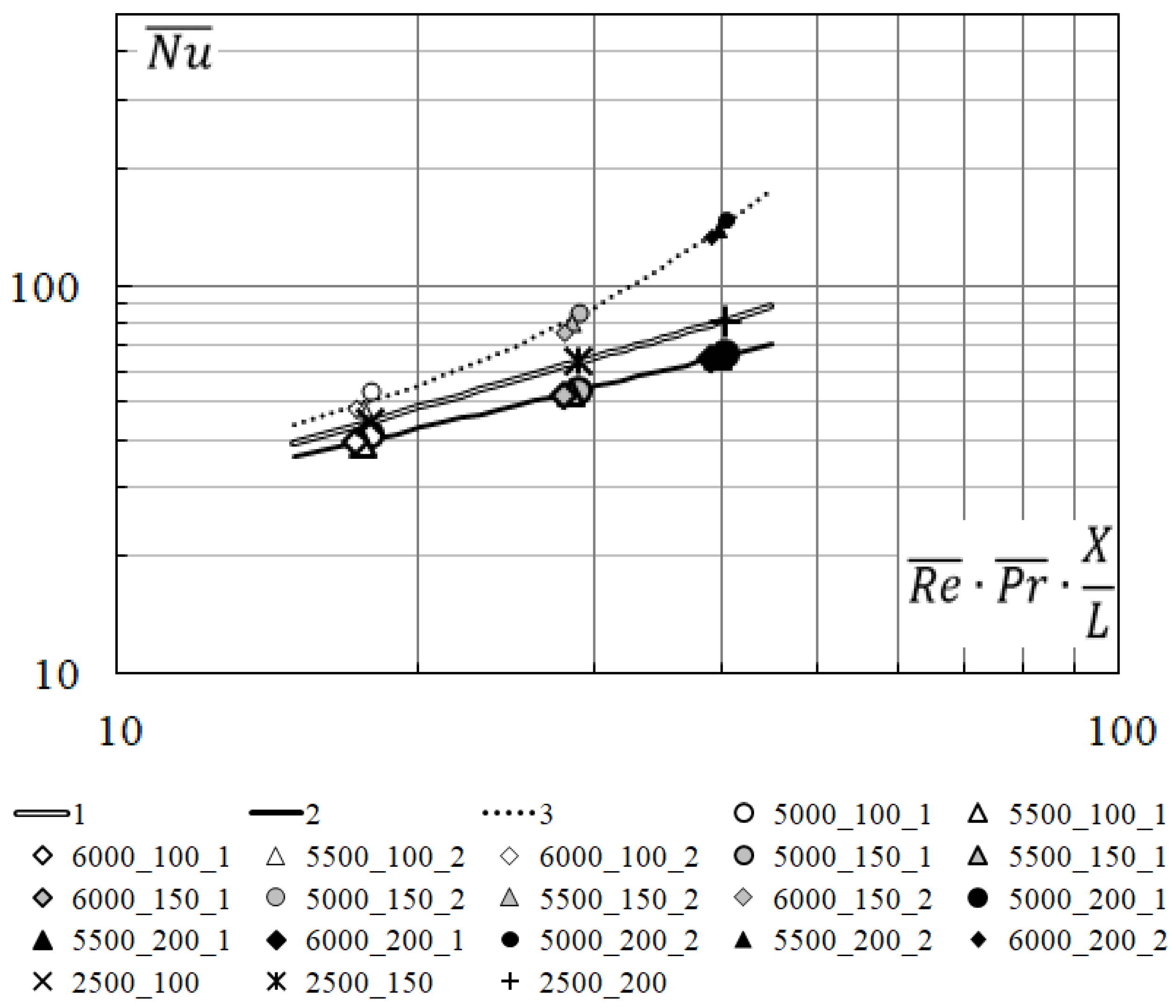
Figure 14 and
Figure 16 obtained the qualitatively identical situation—the objective function under symmetric two-sided heat input occupies the intermediate position between the values of the corresponding objective functions on the hot surface and the surface that is non-heated.
Further final processing of the research results consisted in plotting the generalizing dependence of the average Nusselt numbers (
) on the value of the dimensionless coordinate (
). On the graph,
Figure 14 presents the results of researches of complicated heat transfer with the mixed motion of air on the hot surface (curve 2) and the non-heated surface (curve 3); the results of the test research and the results of convective heat transfer in pipes and ducts under turbulent flow regime, published in [
22] (curve 1).
The average Nusselt numbers (
) and (
) are calculated using the known dependence for the average Nusselt number (
), which describes convective heat transfer in pipes and ducts under turbulent flow regime, but using correction factors
where is
—average Nusselt number on the hot surface, curve 2;
—average Nusselt number on the non-heated surface, curve 3;
—average Nusselt number on the symmetrical two-sided heat input, curve 1, Formula (1). The accuracy approximation is (
R2 ≥ 0.98).
The change in the dimensionless average integral temperature head along the length of the dimensionless coordinate for the hot surface (curve 2) and the non-heated surface (curve 3) is shown in
Figure 16. For comparison, the same graph shows the dependence of the average integral temperature head for the case of symmetric two-sided heated input (curve 1).
the accuracy approximation is (
R2 > 0.99).
the accuracy approximation is (
R2 = 0.90).
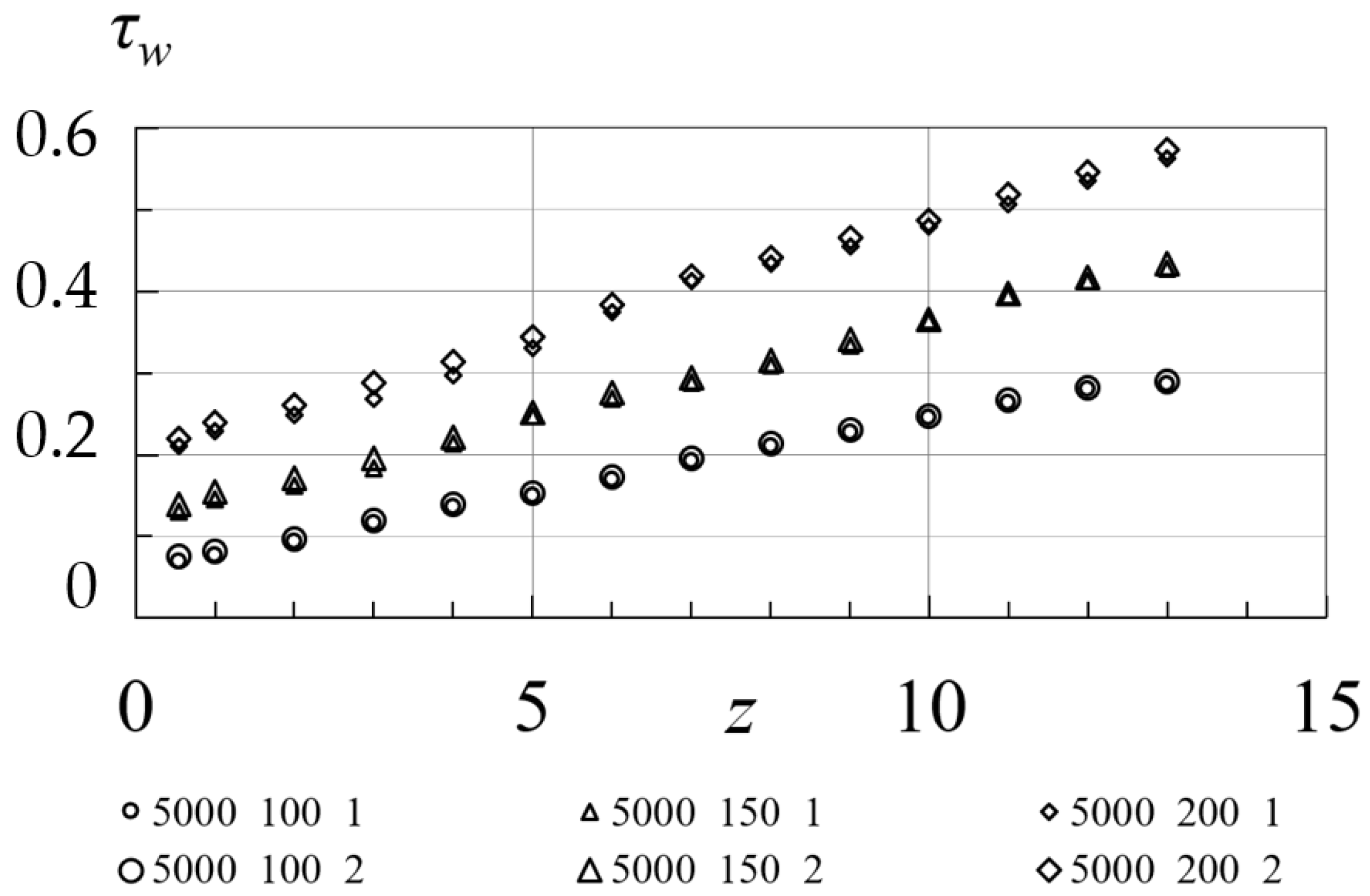
The distribution of tangential stresses on the walls along length of the duct, for different experimental conditions (
W/m
2,
kg/h), is shown in
Figure 17.
The distribution plotting of the value obtained for the value of the heat flux density W/m2 remains relevant for another values . It can be seen that there is the minimal difference in the values of obtained for different duct surfaces. The observed difference may not be considered, and the values of tangential stresses on the walls may be considered the same.
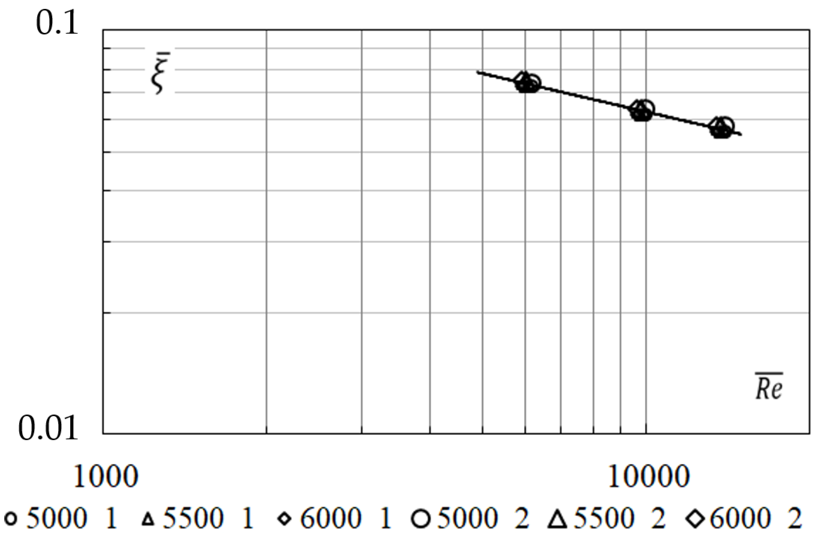
The results of the research are presented in the form of the generalizing dependence of the average coefficient of friction resistance on the value of the dimensionless coordinate (
Figure 18). The generalizing graphical dependence is satisfactorily approximated by the power dependence (6), the accuracy approximation is (
).
6. Conclusions
It is established that in the considered range of values of heat flow density and mass flow rate of air, the dominant heat transfer between the walls and air is complicated convective heat transfer, in which forced convection () is affected by free convection ().
There is the difference in the intensity of convective heat transfer on the hot surface and on the non-heated surface. The difference in the density of heat flux transmitted by convection to air on the hot surface, and the non-heated surface is proportional to the expression () and is 1.5–2.0.
Generalizing dependences are obtained that allow calculating the average Nusselt numbers and average temperature heads on the duct surfaces. Limits for applying dependencies (2)–(5): ; ; .
The generalizing dependence of the value of the coefficient of friction resistance as a function of the value of the dimensionless coordinate (6) is obtained. The obtained values of the resistance value allow us to assume that in the hardware design of high-temperature heat exchangers and heat recuperation systems, the value of pressure losses to overcome the resistance of the boundary layer will not exceed 10% of the total pressure losses in the system.
The research results became the basis for the creation of the engineering methodology for calculating the heat engineering indicators of high-temperature heat exchangers and heat recuperation systems, which are widely used in the production of basalt and glass fibers at the enterprises “Chernivtsi plant of thermal insulation materials” (Chernivtsi, Ukraine) and “Innovation Basalt Technology Sp. z.o.o.”(Gdansk, Poland). Their use in heat technologies allows you to return part of the heat with heated air to the technological cycle, provide controlled cooling of the equipment lining and obtain secondary energy resources in a form that is convenient for further use for one’s own technological needs or sanitary needs of production.


