Abstract
Analyzing the impact of electrical aging on the lithium-ion cell’s mechanical behavior and safety is an important factor to assess the crash safety of electric vehicles during their lifetime. In this study, fresh and electrical aged state-of-the-art NCM pouch cells were investigated. Aged cells, which were cycled electrically to 90% state of health, under laboratory conditions in electric vehicle battery modules were used. The used charging/discharging strategy represents real customer behavior based on accelerated driving profiles. First, it is shown that electrical aging has a significant influence on the anodes’ and separators’ mechanical properties, which had a lower mechanical strength and stiffness under tension. Additionally, quasi-static cylindrical indentation and three-point bending tests were performed to investigate aging effects on cell level at varying state of charge (SOC). Aged cells with 0% SOC showed a right-shifted force–displacement curve and a 29% lower maximum force compared to fresh cells. Fully charged, aged cells reached a similar maximum force to fresh cells, but faster temperature increase and higher temperature peaks after internal short circuit. Inductively coupled plasma optical emission spectrometry analyses confirmed an increased lithium content on the anode surface, which is indicated in literature as a reason for the increased exothermic reaction of the aged cells. The results indicate a higher safety risk for the aged investigated pouch cells under mechanical loads based on their changed mechanical properties and thermal runaway behavior.
1. Introduction
The usage of lithium-ion batteries (LIBs) is of high importance in current, as well as future, electric vehicles (EV) due to a fast increasing market, which is accelerated by ambitious goals against climate change [1]. Besides the continuous improvement of LIBs’ performance in terms of rising energy densities [2], the improvement of their safety performance is also of great importance. Damage and deformations of EV battery systems in a crash situation can cause multiple safety issues [3,4]. For example, external short circuits (ESC) can result in the deformation of electrical conducting components such as cell tabs, high-voltage busbars or cables, and the resulting failure of their insulation layers as described in [5,6,7]. On the other hand, a mechanical, electrical, or thermal abuse of the battery cell itself can lead to an internal short circuit (ISC) caused by separator failure followed by a thermal runaway (TR) [5,8]. Cell deformations can trigger TRs directly by deformation and failure of the separator [8]. The TR mechanisms for a commercial NCM/graphite pouch cell, such as investigated in this study, can be described as a chain of chemical reactions. After the final failure of the separator layer during this process, a high-electric-energy release due to ISC takes place. This can lead to burning electrolytes and, in the worst case, explosions [8].
A basic requirement for preventing TRs is a comprehensive understanding of the processes taking place in the battery cell triggered by an electrical, thermal, or mechanical overload. For example, the behavior of LIBs under mechanical loading has already been studied in a large number of publications. Different cell conditions and influencing factors such as strain rate effects [9,10,11,12,13] and state of charge (SOC) dependence [14,15,16,17,18] were investigated with a focus on safety assessment. Zhu et al. [11] tested dry and wet jelly roll samples and showed that the strain-rate-dependent hardening effect of LIBs is a result of the electrolyte’s flow. Furthermore, it was shown that high strain rates can decrease the maximum force before failure under mechanical loads [12,13]. The SOC dependence of LIBs was mostly analyzed for cylindrical cells [14,16,17,18]. One main conclusion is that increasing SOC levels lead to a higher stiffness of cylindrical cells. This behavior was justified by an induced internal stress by anode expansion due to lithium insertion [14,16]. It was also shown that with increasing SOC, higher failure stresses can occur for cylindrical cells [18]. For pouch cells, scant research is available. Li et al. [16] discovered that the stiffness of pouch cells is higher only for increasing SOC when the expansion is prevented by geometric constraints [16]. Deng et al. [19] also indicated an SOC independence for non-pretensioned pouch cells under mechanical loads in their studies. In order to better understand the behavior of lithium-ion cells under mechanical loads, cell components were also characterized mechanically. Many researchers have focused on analyzing the separator [20,21,22,23,24,25], but some research for the anode and cathode behavior has also been published [26,27]. The aforementioned studies of LIBs’ mechanical behavior focused almost exclusively on fresh cells.
Further publications prove that, beside these mostly investigated influences, degradation effects of electrical aging, also leading to a capacity fade of LIBs [28], must be considered in the safety assessment. These can affect the cells’ TR behavior [29] and mechanical properties [18,22,30,31,32,33]. In addition, some literature is available with respect to the influence of aging on safety. For example, the effects of lithium plating, usually provoked by fast charging profiles and aggravated by low temperatures [34], can have a high impact on the safety of LIBs [29,34,35,36]. Thus, a drastic decrease of the triggering temperature leads to a TR and an increase of maximum temperature can occur during TR [34]. However, the thickening of the solid electrolyte interface (SEI) improves the TR performance by higher thermal stability [29].
Although there is a high importance of electrical aging on the mechanical behavior of LIBs, to the authors’ knowledge, few studies [18,22,30,31,32,33] have been published considering the difference between fresh and electrically aged cells under mechanical loads. Wu et al. [30] investigated electrical aged anode, cathode, and separator materials of a NCM pouch cell. In their studies, only the anode showed significant changes in terms of lower mechanical strength after electrical aging. These mechanical changes of the materials corresponded with significant visual changes of the aged anode in terms of deposition and degradation spots [30]. Fink et al. [31] noticed a similar influence of electrical aging on the anode’s mechanical properties. Additionally, a significant impact on the cathode’s mechanical properties in terms of lower Young’s modulus and tensile strength was mentioned [31]. Zhang et al. [22] showed that electrical aging of an elliptical cell changed the trilayer separator’s (PP/PE/PP) material properties to a lower mechanical strength. On a cell level, a lower strength and failure displacement was noticed. Chemical reaction products in the form of particles, which were stored in the separator pores and might have created stress concentrations that potentially led to earlier failure, were noticed in scanning electron microscopy (SEM) analyses. They also mentioned the physical degradation of the polymer chains as a possible reason for a lower failure strength [22]. Another work investigating electrical aging effects on the mechanical behavior of automotive LIBs was published by Kovachev, et al. [32]. The authors investigated fresh, and at 60 and 1C, electrically aged cells under quasi-static mechanical loads at 100% SOC. Aged cells showed a small decrease in stiffness and a right-shifted force–displacement curve with a higher failure force compared to fresh cells. The softer mechanical response was justified by an additional compression of a thicker SEI layer grown due to side reactions with lost active lithium at the anode’s surface graphite particles. Furthermore, a higher maximum force was noticed before failure. This was interpreted as the effect of a dry separator due to electrolyte decomposition and thus a hardening mechanical behavior [32]. Additionally, Liu et al. [33] investigated the mechanical response of pouch cells at four aging states focusing on low-temperature aging at 0 . They also indicated right-shifted force–displacement curves under mechanical indentation and higher force peaks for aged cells. Cell component tests indicated that aged anodes show a similar behavior. Additionally, a faster energy release after cell failure was detected on a cell level for 20% capacity faded cells, which led to a stronger voltage drop and higher temperature increase at the cell surface [33].
Beside these valuable insights, important influencing factors were neglected in the mentioned studies. The difference of the mechanical behavior’s SOC dependence between fresh and aged cells, as well as the the impact of electrical aging under EV battery module conditions, were not investigated in detail until yet. Therefore, aged cells, which were electrically cycled in EV battery modules with an aging strategy focusing on real customer behavior, were analyzed in this paper. For example, multiscale mechanical tests were performed to investigate the influence of electrical aging and the SOC on the crash behavior of LIBs. Furthermore, several microscopy analyses were chosen to better understand the impact of electrical aging on the mechanical behavior of LIBs and their relevant safety properties.
2. Materials and Methods
2.1. Investigated Lithium-Ion Cell
All investigations in this paper were performed on a state-of-the-art lithium-ion pouch cell with a capacity of 74 Ah. Figure 1 shows the geometry and structure of the cell as well as microscopic analysis and samples used for tensile and compression tests for each cell layer. In order to allow the distinct description of loading directions in the results section, a cell-related coordinate system (u, v, w) was introduced. The coordinate u describes the direction along the cell length, v the cell width, and w the thickness direction. The cell consists of several anodes, cathodes, and one folded separator between the active layers to prevent a short circuit. A 110 m thick cathode material consisting of one aluminum sheet and a LiNiMnCoO (NCM) double-coated layer is used. The anode material is a two-side carbon-coated layer on a copper current collector with a thickness of 120 m. The cell’s separator consists of polyethylene with a ceramic layer based on AlO. Its thickness is about 20 m. A detailed description of the manufacturing process for the test specimens, shown in Figure 1d,e, can be found in Section 2.5.
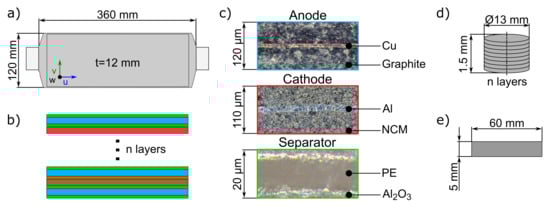
Figure 1.
Overview of the used NCM lithium-ion pouch cell and specimen geometries for the component tests: (a) cell geometry; (b) layer structure: anode (blue), cathode (red), and separator (green); (c) microscopic analyses, (d) test stack of compression test; (e) tensile test specimen.
2.2. Applied Aging Strategy
In order to investigate the influence of electrical aging effects on the mechanical behavior of EV pouch cells in the most realistic way, cells, which were electrically cycled under state-of-the-art EV battery module conditions were used. Several pouch cells were serially connected in the EV module. As expected in an electric vehicle, an aging strategy aiming to describe real customer behavior was chosen. The charging/discharging mix was derived from EV driving profiles with a focus on customers who cause high-performance discharge profiles. The battery was discharged to a minimum SOC of 10% with an average discharge power of kW per cell. For the charging process up to 90% SOC, an average power of kW was applied. The applied ambient temperature ranged from a minimum of to 31 . All aged cells were electrically cycled to a residual state of health (SOH) of 90%.
2.3. Mechanical Test Setup
In order to understand the reasons for the change of the cell’s mechanical properties, fresh and aged cell components, including anode, cathode, and separator, were investigated in this study. For this purpose, fresh and aged cell layers were extracted by cell opening, as described in Section 2.5. Wang et al. [26] showed that the mechanical properties of dry cell layers differ significantly from cell layers soaked in electrolyte. To achieve a high correlation to real cell conditions, all cell components were submerged in dimethyl carbonate (DMC) as a replacement of electrolyte until testing. DMC was chosen due to its low reactivity with the cell component materials. Tensile tests were used to determine the mechanical properties, e.g., mechanical strength, stiffness, and strain failure. The tests were performed on a TA-Instruments DMA RSA-G2 testing machine with a load cell up to 35 N, which has a force resolution of 10−4 N. Furthermore, compression tests were performed on a Zwick Z250 testing machine to analyze the stiffness behavior under pressure and the compressibility of the materials. A load cell of the type Xforce K up to 50 kN measurement capacity with an accuracy of kN was used [37]. The traverse positioning accuracy is about 2 m [38]. Three strain rates , including 1/s, 1 1/s and 7 1/s, were conducted in order to compare the strain-rate effects between fresh and aged cell components as well as the influence on the compressibility. Due to the physical limitations of the testing machines used, a uniform distribution of strain rates had to be neglected. An overview of the performed tests is shown in Table 1.

Table 1.
Mechanical tests for the characterization of the investigated lithium-ion pouch cell and cell components.
Mechanical load tests of fresh and electrically aged cells with varying SOC were considered to investigate the effect of aging on the mechanical behavior of LIBs (see Figure 2). Cylindrical indentation and three-point bending tests were chosen as they describe important load cases that could act on EV battery modules during a crash event [15,39]. The tests were performed analogously to Kovachev et al. [32] on a quasi-static hydraulic press with a displacement resolution of 1 m and a maximum force of 420 kN. The load was applied by a cylindrical impactor with a diameter of 30 mm. As a force measurement instrument, a GMT Serie K 500 kN load cell with an accuracy of % was used. The cell’s electrical voltage was also monitored by using a 24-bit NI-9229 voltage input module with a voltage of up to 60 V per channel. To ensure the electrical isolation of the testing machine in the case of occuring ISCs under cylindrical indentation, a 1 mm thick Pertinax plate (Kaindl, HP2061) was placed between the tested cell and the testing machine [32]. A maximum deformation of up to 50% cell thickness or a complete loss of force were defined as termination criteria during testing. The cells were not clamped.
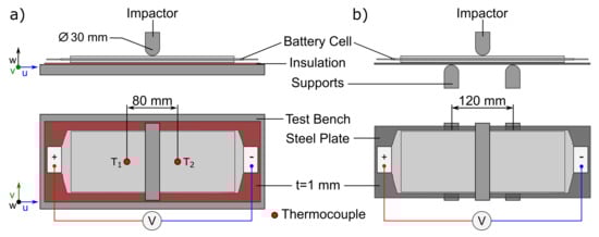
Figure 2.
Experimental setup of the mechanical cell tests: (a) Shows the cylindrical indentation test setup including test bench, insulation plate, cylindrical impactor (Ø30 mm), and the investigated battery cell. (b) Shows the three-point bending test setup with a supporting S235JR steel plate for a realistic cell deformation and two cylindrical supports at a distance of 120 mm (Ø30 mm).
Under three-point bending, the cells were bent between two supports of 30 mm diameter at a distance of 120 mm. The maximum deformation was defined at 50 mm displacement. As no short circuit was expected under this type of load, no insulation plate was used. An S235JR steel plate with 1 mm thickness was positioned under the cell to ensure realistic deformation behavior of the cell under bending according to the battery module’s boundary conditions. Besides the influence of aging effects, the SOC’s influence was also taken into account by testing fresh and aged cells at 0% SOC and 100% SOC. In this case, 100% SOC is related to the fully charged condition of the respective aging state. It was the goal to analyze the safety risks and thermal runaway behavior by measuring the temperature increase after ISC occurs for 100% SOC. Therefore, two thermocouples of type K with an accuracy of ±0.75% were applied symmetrically to the cell middle in a distance of 80 mm along the long cell side. In order to ensure a statistical validation of the results, 100% SOC tests were performed three times. For cell component and cell tests at 0% SOC five repetitions were conducted.
2.4. Post-Mortem Analyses
Several post-mortem analyses were conducted to investigate the effects of electrical aging and the reasons for changed material properties of single cell components. First, the cell thickness of fresh and electrical aged cells was scanned using a 3D-measurement FaroArm® Platinum with an accuracy of mm [40]. Additionally, visual inspections of the cell components’ surface and different microscopic analyses were performed to analyze the aging effects on the cell components. SEM was carried out to investigate changing of the material’s morphological structure through electrical aging. For this purpose, a Tescan VEGA 3 XLH Scanning Electron Microscope was used. The investigated specimen of 5 mm diameter was obtained from a conspicuous spot on the anode surface. Due to potential lithium plating effects during aging and the resulting safety risks, it was decided to also investigate lithium deposits on the anode surface. The loss of active lithium on the cell’s anode surface was investigated using inductively coupled plasma optical emission spectrometry (ICP-OES). This method was chosen because different studies have shown that lithium deposits on the anode’s surface measured by ICP-OES directly correlate with the capacity fade and the cell degradation [41,42,43]. In this study, a conspicuous area of the aged anode surface, which indicated lithium plating, was chosen for investigation considering the findings in the work of Cannarella et al. [44]. In the first step of sample preparation, the anode was washed with DMC in a glove box. Afterwards, the graphite layer was scraped off and solved in an acid mixture of /. According to Waldmann et al. [43], this method was used to exclude changes of the chemical composition. All nondissolved components were subsequently removed using a red ribbon filter. After ensuring that a complete dissolution was present, the sample was introduced into a plasma together with argon in the form of an aerosol. In the following, the elements to be analyzed were stimulated to optical emission. The emitted light was separated into individual beams with an element-specific wavelength. Due to the light intensity and the element specific wavelength, all elemental components could be detected. For further information, the reader is referred to the work of Waldmann et al. [42,43]. All tests were performed using a Spectroblue FMS with an integrated Spectro Cross Flow nebulizer and a Scott AD36/Duran spray chamber. Additional information of the operation settings can be found in Table 2.
Table 2.
Operation settings for the performed ICP-OES analyses of fresh and aged cell components.
2.5. Test Preparation for Mechanical Testing and Specimen Geometry
The charging/discharging window of the investigated cell was defined between V and V with a nominal voltage of V. The 0% SOC cells were prepared by CC-CV (C/30) discharge with 24 h relaxation. Further cells were charged to 100% SOC with 24 h relaxation to investigate the fully charged condition.
As a first step to produce the cell component specimens, the battery cell was opened in an argon-flooded glove box at a room temperature of 20 . Thus, a chemical reaction of the cell components with oxygen could be prevented. After slicing the pouch foil on the cell edges, the cell layers were extracted carefully, visually inspected, washed, and preserved in DMC as a replacement of electrolyte. The specimen manufacturing was performed under wet conditions. An overview of the specimen geometries can be seen in Figure 1d,e. For the tensile tests, cell layers were cut into mm mm rectangular specimens along the u and v direction of the cell considering ASTM D822-02 and ASTM D6287-98 standards. Therefore, a conventional paper-cutting machine was used. Due to the low thickness of the individual layers, several cell layers had to be stacked on top of each other to generate the specimens for the compression tests. Following the findings in the work of Cannarella et al. [20], a mm specimen thickness was chosen, to avoid an influence of the layer number on the mechanical properties of the cell components. The final 13 mm diameter specimen stack was produced by punching. In order to ensure the same material direction in one stack, the required number of layers to generate the mm thickness was punched directly together. All specimens were placed back in a glass of DMC after manufacturing until the begin of testing.
The aged cell components had to be treated more carefully because of potential lithium deposits on their surface. Due to a high reactivity of lithium in oxygen, the electrical aged specimens were stored for a short time in oxygen before mechanical testing to provoke potential exothermic reactions of lithium deposits on the cell components’ surface. This was performed in order to prevent potential safety issues in terms of fire occurring. A surface temperature increase from 20 to 36 was noticed, indicating an exothermic reaction of lithium deposits with oxygen. After the surface temperature returned to 20 , the specimens were preserved in DMC again.
3. Results
First, tensile and compression tests of the cell components, including anode, cathode, and separator, are presented as they are of high importance to understand the influence of electrical aging on the mechanical properties of lithium-ion cells. In a next step, mechanical abuse tests of fresh and electrically aged cells are conducted. Finally, the results of the microscopic analyses including SEM, visual inspection, and ICP-OES are presented. All curves in the following figures show the calculated average curves of each investigated parameter. In order to consider the spread of experimental data, the minimum and maximum values are marked additionally in the diagrams in terms of error bars.
3.1. Cell Component Tests
The tensile test results of the cell components, containing the stress–strain curves, values of Young’s modulus, and tensile strength of the anode and cathode material, are presented in Figure 3. Besides the aging state, the cell directions u (long side) and v (short side) are shown to analyze if the investigated cell components show an anisotropic behavior under tension. Analyzing Figure 3a,b, a significant dependency of the anode material’s mechanical behavior under tension due to aging effects can be noticed. The aged anode material shows a lower mechanical strength and softer response under mechanical loading. Analyzing the tensile strength, approximately 25% lower values can be noticed compared to the fresh material. In addition, a 50% lower failure strain and 30% lower Young’s modulus can be observed. The failure of the material for both aging states originated from a straight crack in the middle of the specimen.
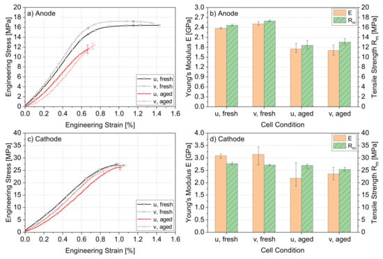
Figure 3.
Mechanical test results under tension for fresh and electrically aged anode (Cu–graphite) and cathode (Al–NCM) materials in different cell directions: (a) Shows the anode’s stress–strain curves and (b) the anode’s Young’s modulus and tensile strength. Analogously, the results of the cathode are shown in (c,d).
These aging effects could be justified by a changed morphological structure of the copper current collector based on high temperatures during electrical cycling. Such an effect could occur as the temperatures would increase the material’s structural transformation temperature. This influence can be excluded by considering the maximum temperature of 36 that EVs are subjected to under typical climate conditions [45]. It has to be mentioned that cell temperatures inside the battery probably reached higher values. Nevertheless, considering LIBs’ maximum temperature development during operation of up to 54 for an ambient temperature of 40 [46], any influence from temperature effects can be excluded. On the other hand, pitting holes due to strong oxidation effects from the interaction of copper with the electrolyte [47] could result in a lower mechanical strength. In this study, no oxidation effects were observed by visual inspection. Liu et al. [33] tested copper and graphite as single materials in their study. They concluded that electrical aging has a low influence on the copper current collector’s mechanical behavior. For graphite, a high impact was noticed under tension. In summary, changes of the graphite’s morphological structure are the most probable reason.
As mentioned before, besides the aging effects, the mechanical anisotropic behavior was also investigated by analyzing the u and v direction of the cell. By considering the indicated error bar of the curves, it can be seen that a low difference of 5% can be observed at the maximum stress values for the fresh anode material in both directions. The aged anode shows very similar behavior, indicating a low anisotropy as well. Wang et al. [26] concluded this behavior for fresh anodes. Comparing the two-side-coated aluminum collector with NCM in Figure 3c,d with the anode, a lower influence of electrical aging on the mechanical behavior of the cathode can be determined. The fresh and aged stress–strain curves show a very similar characteristic tensile strength and failure strain. An 8% lower tensile strength is observed for the aged cathode in the v direction. The Young’s modulus shows a lower mean value for the aged material of 20% in the u direction. In this case, it has to be mentioned that there is a wide statistical spread, which has to be taken into account and therefore indicates a low aging effect on the mechanical behavior of the cell’s cathode material. This behavior was also noticed by Liu et al. [33]. Considering the direction-dependent properties, the NCM–aluminum cathode can be described as an isotropic material. This cathode behavior is different compared to the mentioned anisotropic behavior of lithium nickel cobalt aluminum oxide (NCA) in the work of Wang et al. [26]. A different Young’s modulus of about 44%, depending on the cell direction, was observed under tension [26].
Figure 4 visualizes the experimental results of the separator’s tensile tests. The PE separator shows a significant dependency on the aging state. The determined maximum tensile strength has values of up to 50% lower. Unlike the anode and cathode, the separator shows necking behavior before mechanical failure under tension. In addition, an anisotropic behavior can be noticed with a different tensile strength of up to 17% for the fresh material.
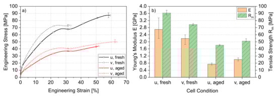
Figure 4.
Experimental results of the tensile test for fresh and electrically aged polyethylene separators in different cell directions: (a) Shows the stress–strain curves and (b) the comparison of Young’s modulus and tensile strength.
Possible reasons for the changed material behavior during electrical aging could be the induced mechanical stress from the cell’s volume expansion, while charging/discharging. This can lead to damage of the separator’s lamellar crystals and also pore closure, according to [48,49]. The influence of the cell’s operating temperature spread can be excluded due to polyethylene’s low glass transition temperature of up to [50]. Furthermore, the wet condition of the separator in the pouch cell could have influenced the degradation and also the mechanical properties. While opening the cell for specimen preparation, most of the electrolyte was noticed at the separator.
Figure 5 shows the compression test’s stress–strain curves in the main diagram, and additionally the first range between 0% and 9% engineering strain in the sub-diagram. In addition, three different impactor velocities were tested to analyze strain rate effects on the mechanical behavior. All three materials show a strain-rate dependence under compression. This behavior can be explained by a reduced reaction time for the materials response in terms of displacement [51]. As a result, the stress shows increased values, especially in the beginning. A neglecting of the compressible behavior of the materials can be noticed, which can play a significant role for dynamic load cases on lithium-ion cells in future investigations.
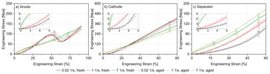
Figure 5.
Comparison of compression test results of fresh and aged cell components considering different strain rates: (a) anode, (b) cathode, and (c) separator.
By analyzing the beginning of the curve, the aged anode material shows a softer mechanical response at a strain rate of 1/s and 1 1/s compared to the fresh one. This behavior can be explained by the growth of an additional layer on the SEI layer in terms of decomposition products through electrical aging. Similar effects were noticed in the work of Kovachev et al. [32] on cell level under quasi-static indentation loads. Therefore, further investigations in terms of SEM analyses are presented in Section 3.4, which confirm this argumentation. In addition, fresh and aged anodes show a force drop at about 50% engineering strain for strain rates of 1/s and 1 1/s. At this point, a brittle cracking behavior of the graphite layer was observed. This behavior was also seen in the work of Wu et al. [30].
The cathode material shows very similar curve characteristics in both aging states for each strain rate. No significant difference can be observed except low differences for the stress values. This was expected after analyzing the tensile test results.
Compared with the results under tension, the separator’s mechanical behavior under compression is less dependent on electrical aging. The variance for fresh and aged stress–strain curves is low. The different impact of electrical aging on the mechanical properties for tension and compression can be explained by the morphological structure of the separator. In order to allow lithium ions to pass during the charging/discharging process, the separator is deliberately porous. Under tension, stress is applied along the weakest point, in this case the pores, and these crack more easily. In an aged cell, this material is more brittle and has lower strength. In contrast, load is applied in the thickness direction and not along the pores under compression, so there is no failure and also no lower strength. Despite the reduced aging influence under compression, it has to be mentioned that the aged material shows slightly increased stress values. Zhang et al. [22] showed that decomposition products, caused by electrical aging, can close separator pores. Thus, the higher strength of the aged material could be explained by closed pores under compression.
3.2. Tests on Cell Level
After analyzing the test results on cell component level, the test results of the whole lithium-ion pouch cells are presented. Figure 6 visualizes the fresh and aged cells’ force–displacement curves for (a) cylindrical indentation and (b) three-point bending at 0% SOC and 100% SOC. The voltage vs. displacement is also illustrated to show the point of occurring ISC based on a voltage drop. Through analyzing the test results in Figure 6a, a simultaneous force and voltage drop under cylindrical indentation can be noticed, which indicates a direct correlation between mechanical cell failure and occurring ISC. This correlation was already described in different studies [52,53]. Furthermore, a high influence of electrical aging on the mechanical properties at cell level can be mentioned. Considering the test results of the anode material under compression in Section 3.1, a similar influence on the mechanical properties by electrical aging can be noticed. The aged cells show a softer mechanical response indicated by a right-shifted force–displacement curve, which was also noticed in the work of Kovachev et al. [32] for pouch cells. In addition, the mechanical behavior of aged cells shows a higher dependence on the investigated SOC levels compared to fresh cells. While fresh cells have a different maximum force of up to 4% depending on their SOC, the aged cells at 0% SOC show a lower maximum force of about 30% compared to the fully charged condition. That also represents a 29% lower force compared to fresh cells for 0% SOC, which is a different behavior compared to the literature [32,33]. In both studies, a higher failure force for aged cells was observed at 0% SOC. Furthermore, the spread of failure displacement for fresh cells in contrast to aged cells dependent on their SOC is very low. Another aspect which has to be taken into account is the different voltage drop after occurring ISC between fresh and aged cells. For both SOC conditions, aged cells show a stronger voltage drop after cell failure.
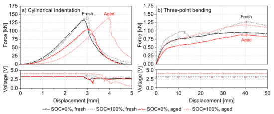
Figure 6.
Comparison of the mechanical behavior of fresh and electrically aged lithium-ion cells under different load cases: (a) cylindrical indentation and (b) three-point bending.
The test results of three-point bending confirm the fact that electrical aging leads to lower mechanical properties at cell level. As mentioned previously, under cylindrical indentation, a high SOC dependence of aged cells can be reported. The maximum force at fully charged condition is about 25% higher for electrical aged cells under three-point bending compared to 0% SOC. For fresh cells, a similar behavior can be noticed. By comparing the fresh and aged cells at the same SOC, it can be seen that, similar to cylindrical indentation, fresh cells show a higher maximum force of up to 22%. It has to be mentioned that, in contrast to cylindrical indentation, no ISC was detected for three-point bending up to displacements of 50 mm for all investigated cell conditions. This can be explained by the low compression of the cell components inside the cell during deformation. The main deformation is caused by bending without a local concentrated fracture zone. Under cylindrical indentation, the machine bed restricts the deformation of the cell in the w direction, which results in high local stress concentrations in the cell under the contacting impactor area. This can lead to a higher local plastic compression of the cell components inside the cell with a higher interaction between the single layers. Thus, a fracture of the cell components occurs, which leads to an ISC.
In order to compare fresh and aged cells with a focus on safety behavior in crash situations, it is not only the mechanical behavior that must be taken into account. In addition, the temperature evaluation after ISC can be used to investigate potential risks caused by TR. As already announced, two thermocouples (T, T) were installed on the cell surface at a distance of 80 mm for 100% SOC cylindrical indentation tests, as shown in Figure 7b. Additionally, Figure 7a illustrates the average temperature increase for each thermocouple after cell failure and ISC (t = 0 s), which indicates a TR. The observed cell behavior can be categorized in four stages. First, the ISC occurs, followed by the formation of smoke at 2 s. In a next step, at 5 s after ISC, a bloating of the cell can be noticed through gas exposition. In the last step, the pouch foil mechanically fails, which leads to a strong exothermic reaction and, as a result, to fire.
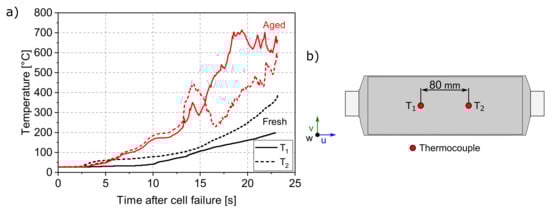
Figure 7.
(a) Comparison of temperature increase after ISC for fresh and aged lithium-ion cells at 100 SOC under cylindrical indentation, where t = 0 s represents the moment of cell failure leading to ISC. (b) Position of the thermocouples type K installed on the cell for temperature measurement.
Analyzing the safety risks of fresh and aged cell conditions, it has to be mentioned that only one out of three fresh cells started to burn after cell failure in this experiment. In conclusion, the aged cells indicated a higher affinity to burn with two of three cells. By analyzing the temperature profile in Figure 7a, it can be seen that the fire affinity of aged cells is higher. Furthermore, aged cells show a higher reactivity, which leads to a faster temperature increase in the first 5 s. In addition, the determined maximum temperatures show higher values of up to 75% compared to fresh cells and indicate a higher safety risk of aged cells after cell failure. Considering the findings in the work of Kovachev et al. [54], a lower thermal conductivity of aged cells could have led to heat accumulation and, as a result, to higher temperatures [54]. Another reason could be the deposition of lithium at the anode surface by lithium plating during charging and discharging. A temperature increase at oxygen could already be described in Section 2.5. Further investigations in terms of ICP-OES analyses are shown in Section 3.5, which confirm the existence of increased lithium deposits on the aged anode surface.
3.3. Thickness Measurement
Table 3 shows the thickness of fresh and aged cells, which was measured before testing to compare the aged cells’ growth due to electrical aging compared to fresh cells. Eight predefined geometric points on the cell surface per cell were evaluated. The mean thickness represents the average value of all tested cells per state. It can be observed that aged cells with 0% SOC are up to % thicker than fresh cells. Furthermore, the volume expansion due to charging is higher for electrical aged cells, which indicates a higher SOC influence. Aged cells at 100% SOC show a % increased cell thickness compared to fresh cells.
Table 3.
Thickness comparison of fresh and aged cells dependent on the cell’s SOC measured with FaroArm® Platinum.
Compared to the literature [32,33], in the present work, a similar cell thickness growth for 0% SOC at a higher SOH level is reached. Kovachev et al. [32] and Liu et al. [33] noticed a cell thickness increase of about 6% and 8% for cells with an approximate SOH of 70% and 0% SOC. Both studies used an aging strategy with a constant ambient temperature and a low charging/discharging power. In contrast, in the present work, a high-performance aging strategy with an ambient temperature window between and 31 was used. Higher charging rates and temperature variation could have directly caused stress concentrations within the anode material, which could have led to stronger rupture of the SEI layer. As a result, an accumulative reaction between the electrolyte and the active material may have occurred, leading to a faster increase in cell thickness [55].
3.4. SEM Analysis
As already shown, the changes of the cell’s mechanical properties and characteristic behavior due to electrical aging are very similar to the changes of the electrical aged anode material. Figure 8 shows different microscopic magnifications for the fresh and aged anode material.
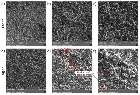
Figure 8.
SEM analysis of the fresh (a–c) and aged (d–f) anode surface at different magnifications. The aged anode surface shows, in several places, products of decomposition due to electrical aging.
At first glance, no difference in the anode’s morphological structure can be noticed at the lowest magnification. In addition, no change in the graphite particle size can be determined due to aging. The main difference, which can be detected by electrical aging, is the appearance of an additional layer on the graphite particles’ SEI layer. The generated layer can be traced back to the decomposition of different products from the interaction between the electrolyte and the anode’s surface during the battery operation. A similar aging effect was described in the work of Kovachev et al. [32]. The softer mechanical response for aged lithium-ion cells under mechanical abuse was justified with the grown layer on the SEI [32]. Liu et al. [33] also noticed a similar additional layer on the graphite particles, which was described as a “mossy material”. It was assumed that the grown layer could be lithium dendrites [33]. The aged anode’s softer mechanical behavior, mentioned in both studies, could be confirmed by the compression tests performed in the present work (see Section 3.1). On a cell level, a right-shifted force-displacement curve was also observed. As described in the work of Kovachev et al. [32], this can be explained with a higher elasticity of the additional layer compared to the graphite particles, which is compressed under mechanical loading. Furthermore, it has to be mentioned that these decomposition products show a nonhomogeneous structure. Additionally, there was no equal distribution on the anode surface for these aging phenomena noticed in this study. This could have led to a more rough and nonplanar anode surface compared to fresh cells. Analyzing the observed cell failure at lower force levels for aged cells at 0% SOC in Section 3.1, these noticeable spots on the anode surface could have caused local stress concentrations inside the cell, which resulted in an earlier failure of the separator and ISC compared to fresh cells. The 50% lower mechanical strength and higher brittleness of the aged separator under tension, which was noticed in Section 3.1, could have increased this effect.
3.5. Optical Assessment and ICP-OES Analysis
Figure 9a shows the anode’s results of ICP-OES analyses and Figure 9b,c of the visual inspection. Neither optical inspection nor ICP-OES analysis revealed any unexpected changes for the cathode material, which is why they are not shown in this section. For a review of the cathode’s ICP-OES results, the reader is referred to the Appendix A Figure A1.
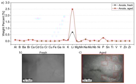
Figure 9.
Lithium deposition effects for fresh and aged cells: (a) Shows the ICP-OES results with 355% higher lithium deposits on the aged anode surface compared to the fresh sample. (b,c) Show the visual comparison between fresh and aged anode samples. Significant changes of the aged anode surface in terms of white ring shaped spots, which indicate lithium plating effects, are highlighted.
In contrast, the comparison between the fresh and aged anode surface shows some significant differences. The aged anode exhibits several white colored spots in a ring shape (red marked), which indicate lithium plating according to Cannarella et al. [44]. These local spots can be caused by pore-closure effects of the separator and thus high current concentration during the charging/discharging process [44]. The results of ICP-OES analysis in Figure 9a confirm the expectation of increased lithium deposits on the electrical aged anode surface. The amount of lithium increased by 355% compared to the fresh sample. In contrast, the weight percentages of all other elements examined are unchanged. These results can explain the elevated temperatures of the anode’s surface at oxygen, which were described in Section 2.5 for the disassembling process. Furthermore, the cell’s temperature increase after ISC for 100% SOC cells under mechanical loading can be explained by a higher exothermic reaction of lithium deposits on the anode surface. The first phase of TR, describing the exothermic decomposition of the SEI layer [8], could be accelerated due to faster temperature increase by reacting lithium depositions at the aged anode surface. Furthermore, the lithium deposition results in a more probable contact of lithium and electrolyte for aged cells after failure. This can be a reason for higher maximum temperatures after occurring fire. Analyzing the potential risk of this insight, the elevated temperatures of aged cells could also lead to an easier thermal propagation between neighboring cells in an EV battery module.
4. Summary and Conclusions
In this paper, fresh and electrical aged lithium-ion pouch cells were compared with a focus on their mechanical behavior in crash situations. The aged cells were electrically cycled under EV battery module conditions to 90% SOH. In order to analyze the main changes of aged cells relevant for crash safety, multiscale investigations in terms of mechanical cell component and cell level tests at 0% and 100% SOC were performed. Additionally, a detailed post-mortem analysis was conducted to investigate the main degradation effects leading to changed material behavior and potential safety issues.
It was shown that electrical aging influences the mechanical behavior of the anode and separator material. For both materials, a significantly lower failure strength and failure strain was noticed under tension compared to fresh samples. The separator material also showed increased anisotropic behavior with different failure strains and tensile strengths for both aging states. In contrast, no significant effect of electrical aging or anisotropy was found for the NCM cathode’s mechanical properties. In a next step, stack compression tests were performed under three different strain rates for fresh and aged cell components. A high strain-rate dependence was noticed for anode, cathode, and separator, indicated by increased stress values at higher strain rates and a neglect of the material-specific compressible behavior. Overall, a minor effect of aging on the mechanical properties was observed in the compression tests. Only the aged anode showed a slight right-shifted stress–strain curve compared to the fresh material. The results in terms of SEM analyses confirmed the appearance of grown decomposition products on the aged anode’s SEI layer by electrical aging. This can explain the softer mechanical response in the compression tests. The softening behavior was more significant at cell-level tests. The anode showed a great influence under cylindrical indentation loads due to high cell component compression, which was also reported in different publications. Furthermore, it was shown that cylindrical indentation is the critical load case in crash situations compared to three-point bending due to occurring internal short circuits for fresh and aged cells. Despite a simultaneous drop in force and voltage for both aging states, a stronger voltage drop for aged cells was noticed. In addition, lower failure forces of about 29% were determined for aged cells at 0% SOC, which was explained by local induced stress concentrations due to decomposition products and a lower mechanical strength of the aged separator. In addition, a stronger SOC dependence for aged cells was noticed. Furthermore, the 100% SOC cylindrical indentation tests indicated a more critical TR event for aged cells with increased maximum temperatures of up to 75% and a faster TR. This behavior was justified by ICP-OES analyses, where increased lithium deposits of about 355% were detected at the aged anode’s surface compared to fresh cells. In the authors’ opinion, this, among other effects, could have led to stronger reactions during exothermic decomposition of the SEI layer in the TR event and, consequently, to higher temperatures. An increased temperature development during TR caused by lithium plating effects could also be reported in several studies.
The mentioned insights are particularly important to consider for future battery design, as electrical aging can affect the mechanical response and TR behavior of the entire battery in crash situations. Based on the obtained results in this paper, the following conclusions were defined:
- The investigated NCM pouch cell shows a simultaneous force drop and occurring internal short circuit, which indicates a direct relation between mechanical failure and internal short circuit.
- Aged cells show a right-shifted force–displacement curve under cylindrical indentation, which seems to be a result of an additional layer on the anode’s SEI.
- The mechanical behavior of aged cells shows a greater dependence on SOC compared to fresh cells.
- High deformation of aged cells can result in lower failure forces of about 29%, which can be explained as an effect of local induced stress concentrations by products of decomposition and lower mechanical strength of aged separator materials.
- Aged cells can show a stronger voltage drop and higher temperatures after internal short circuit compared to fresh cells, which indicates a higher safety risk in EVs.
- When analyzing thermal runaway and thermal propagation behavior, special degradation mechanisms such as lithium plating caused by certain electrical cycling profiles should be considered, as they can change the temperature development after cell failure.
Author Contributions
Conceptualization, M.S., M.R. and F.S.; methodology, M.S.; software, M.S.; validation, M.S.; formal analysis, M.S.; investigation, M.S. and M.R.; resources, M.S.; data curation, M.S.; writing—original draft preparation, M.S.; writing—review and editing, N.D., F.S., C.E. and W.S.; visualization, M.S.; supervision, N.D. and W.S.; project administration, M.S. All authors have read and agreed to the published version of the manuscript.
Funding
Parts of this work were conducted in the research project SafeLIB. The COMET Project SafeLIB is funded within the framework of COMET-Competence Centers for Excellent Technologies by BMK, BMDW, the Province of Upper Austria, the province of Styria, as well as SFG. The COMET Program is managed by FFG.
Institutional Review Board Statement
Not applicable.
Informed Consent Statement
Not applicable.
Data Availability Statement
Not applicable.
Acknowledgments
The authors thank Severin Hahn, Rainer Schwarz, and Tobias Werling for the technical exchange. We thank Wolfgang Märkle for the preparation of the SEM images. We thank Jochen Kirres and Stefan Mast for the ICP-OES measurements. We also thank Georgi Kovachev and Sebastian Stolte for assistance with the experimental work. The responsibility for this publication lies with the authors.
Conflicts of Interest
The authors declare no conflict of interest.
Abbreviations
The following abbreviations are used in this manuscript:
| 3PB | Three-point bending |
| Al | Aluminum |
| Cu | Copper |
| DMC | Dimethyl carbonate |
| ESC | External short circuit |
| EV | Electric vehicle |
| ICP-OES | Inductively coupled plasma optical emission spectrometry |
| ISC | Internal short circuit |
| LIBs | Lithium-ion batteries |
| NCA | Lithium nickel cobalt aluminum oxide |
| NCM | Lithium nickel manganese cobalt oxide |
| PE | Polyethylene |
| PP | Polypropylene |
| SEI | Solid electrolyte interface |
| SEM | Scanning electron microscopy |
| SOC | State of charge |
| TR | Thermal runaway |
Appendix A

Figure A1.
ICP-OES results of the fresh and aged cathode material.
References
- International Energy Agency. Global EV Outlook. 2021. Available online: https://www.iea.org/reports/global-ev-outlook-2021/trends-and-developments-in-electric-vehicle-markets (accessed on 19 December 2021).
- Wu, X.; Song, K.; Zhang, X.; Hu, N.; Li, L.; Li, W.; Zhang, L.; Zhang, H. Safety Issues in Lithium Ion Batteries: Materials and Cell Design. Front. Energy Res. 2019, 7, 65. [Google Scholar] [CrossRef] [Green Version]
- Wang, Q.; Mao, B.; Stoliarov, S.I.; Sun, J. A review of lithium ion battery failure mechanisms and fire prevention strategies. Prog. Energy Combust. Sci. 2019, 73, 95–131. [Google Scholar] [CrossRef]
- Liu, B.; Jia, Y.; Yuan, C.; Wang, L.; Gao, X.; Yin, S.; Xu, J. Safety issues and mechanisms of lithium-ion battery cell upon mechanical abusive loading: A review. Energy Storage Mater. 2020, 24, 85–112. [Google Scholar] [CrossRef]
- Abaza, A.; Ferrari, S.; Wong, H.K.; Lyness, C.; Moore, A.; Weaving, J.; Blanco-Martin, M.; Dashwood, R.; Bhagat, R. Experimental study of internal and external short circuits of commercial automotive pouch lithium-ion cells. J. Energy Storage 2018, 16, 211–217. [Google Scholar] [CrossRef]
- Werling, T.; Geuting, P.; Höschele, P.; Ellersdorfer, C.; Sinz, W. Investigation of the electro-mechanical behavior of automotive high voltage busbars under combined electrical load with varying indenter geometry and environmental conditions. J. Energy Storage 2020, 32, 101861. [Google Scholar] [CrossRef]
- Werling, T.; Sprenger, M.; Ellersdorfer, C.; Sinz, W. Experimental and Numerical Investigation of the Behavior of Automotive Battery Busbars under Varying Mechanical Loads. Energies 2020, 13, 6572. [Google Scholar] [CrossRef]
- Feng, X.; Ouyang, M.; Liu, X.; Lu, L.; Xia, Y.; He, X. Thermal runaway mechanism of lithium ion battery for electric vehicles: A review. Energy Storage Mater. 2018, 10, 246–267. [Google Scholar] [CrossRef]
- Xu, J.; Liu, B.; Wang, L.; Shang, S. Dynamic mechanical integrity of cylindrical lithium-ion battery cell upon crushing. Eng. Fail. Anal. 2015, 53, 97–110. [Google Scholar] [CrossRef]
- Kisters, T.; Sahraei, E.; Wierzbicki, T. Dynamic impact tests on lithium-ion cells. Int. J. Impact Eng. 2017, 108, 205–216. [Google Scholar] [CrossRef]
- Zhu, J.; Luo, H.; Li, W.; Gao, T.; Xia, Y.; Wierzbicki, T. Mechanism of strengthening of battery resistance under dynamic loading. Int. J. Impact Eng. 2019, 131, 78–84. [Google Scholar] [CrossRef]
- Kisters, T.; Kuder, J.; Töpel, A.; Langkemper, R.; Nau, S.; Schopferer, S. Strain-rate dependence of the failure behavior of Lithium-Ion pouch cells under impact loading. J. Energy Storage 2021, 41, 102901. [Google Scholar] [CrossRef]
- Tancogne-Dejean, T.; Grolleau, V.; Mohr, D. Strain rate dependent plasticity of lithium-ion pouch cells: Experiments and simulations. Int. J. Impact Eng. 2022, 159, 104048. [Google Scholar] [CrossRef]
- Xu, J.; Liu, B.; Hu, D. State of charge dependent mechanical integrity behavior of 18650 lithium-ion batteries. Sci. Rep. 2016, 6, 21829. [Google Scholar] [CrossRef] [PubMed] [Green Version]
- Xia, Y.; Chen, G.; Zhou, Q.; Shi, X.; Shi, F. Failure behaviours of 100% SOC lithium-ion battery modules under different impact loading conditions. Eng. Fail. Anal. 2017, 82, 149–160. [Google Scholar] [CrossRef]
- Li, W.; Xia, Y.; Zhu, J.; Luo, H. State-of-Charge Dependence of Mechanical Response of Lithium-Ion Batteries: A Result of Internal Stress. J. Electrochem. Soc. 2018, 165, 1537–1546. [Google Scholar] [CrossRef]
- Tsutsui, W.; Siegmund, T.; Parab, N.; Liao, H.; Nguyen, T.; Chen, W. State-of-Charge and Deformation-Rate Dependent Mechanical Behavior of Electrochemical Cells. Exp. Mech. 2018, 58, 627–632. [Google Scholar] [CrossRef]
- Xu, J.; Jia, Y.; Liu, B.; Zhao, H.; Yu, H.; Li, J.; Yin, S. Coupling Effect of State-of-Health and State-of-Charge on the Mechanical Integrity of Lithium-Ion Batteries. Exp. Mech. 2018, 58, 633–643. [Google Scholar] [CrossRef]
- Deng, J.; Smith, I.; Bae, C.; Rairigh, P.; Miller, T.; Surampudi, B.; L’Eplattenier, P.; Caldichoury, I. Impact Modeling and Testing of Pouch and Prismatic Cells. J. Electrochem. Soc. 2020, 167, 090550. [Google Scholar] [CrossRef]
- Cannarella, J.; Liu, X.; Leng, C.Z.; Sinko, P.D.; Gor, G.Y.; Arnold, C.B. Mechanical Properties of a Battery Separator under Compression and Tension. J. Electrochem. Soc. 2014, 161, 3117–3122. [Google Scholar] [CrossRef] [Green Version]
- Zhang, X.; Sahraei, E.; Wang, K. Deformation and failure characteristics of four types of lithium-ion battery separators. J. Power Sources 2016, 327, 693–701. [Google Scholar] [CrossRef]
- Zhang, X.; Zhu, J.; Sahraei, E. Degradation of battery separators under charge–discharge cycles. RSC Adv. 2017, 7, 56099–56107. [Google Scholar] [CrossRef] [Green Version]
- Yan, S.; Huang, X.; Xiao, X. Measurement of the through thickness compression of a battery separator. J. Power Sources 2018, 382, 13–21. [Google Scholar] [CrossRef]
- Ding, L.; Zhang, C.; Wu, T.; Yang, F.; Cao, Y.; Xiang, M. The compression behavior, microstructure evolution and properties variation of three kinds of commercial battery separators under compression load. J. Power Sources 2020, 451, 227819. [Google Scholar] [CrossRef]
- Bulla, M.; Kolling, S.; Sahraei, E. An Experimental and Computational Study on the Orthotropic Failure of Separators for Lithium-Ion Batteries. Energies 2020, 13, 4399. [Google Scholar] [CrossRef]
- Wang, L.; Yin, S.; Zhang, C.; Huan, Y.; Xu, J. Mechanical characterization and modeling for anodes and cathodes in lithium-ion batteries. J. Power Sources 2018, 392, 265–273. [Google Scholar] [CrossRef] [Green Version]
- Pan, Z.; Li, W.; Xia, Y. Experiments and 3D detailed modeling for a pouch battery cell under impact loading. J. Energy Storage 2020, 27, 101016. [Google Scholar] [CrossRef]
- Birkl, C.R.; Roberts, M.R.; McTurk, E.; Bruce, P.G.; Howey, D.A. Degradation diagnostics for lithium ion cells. J. Power Sources 2017, 341, 373–386. [Google Scholar] [CrossRef]
- Ren, D.; Hsu, H.; Li, R.; Feng, X.; Guo, D.; Han, X.; Lu, L.; He, X.; Gao, S.; Hou, J.; et al. A comparative investigation of aging effects on thermal runaway behavior of lithium-ion batteries. eTransportation 2019, 2, 100034. [Google Scholar] [CrossRef]
- Wu, Z.; Cao, L.; Hartig, J.; Santhanagopalan, S. (Invited) Effect of Aging on Mechanical Properties of Lithium Ion Cell Components. ECS Trans. 2017, 77, 199–208. [Google Scholar] [CrossRef]
- Fink, K.; Santhanagopalan, S.; Hartig, J.; Cao, L. Characterization of Aged Li-Ion Battery Components for Direct Recycling Process Design. J. Electrochem. Soc. 2019, 166, 3775–3783. [Google Scholar] [CrossRef]
- Kovachev, G.; Ellersdorfer, C.; Gstrein, G.; Hanzu, I.; Wilkening, H.M.R.; Werling, T.; Schauwecker, F.; Sinz, W. Safety assessment of electrically cycled cells at high temperatures under mechanical crush loads. eTransportation 2020, 6, 100087. [Google Scholar] [CrossRef]
- Liu, Y.; Xia, Y.; Zhou, Q. Effect of low-temperature aging on the safety performance of lithium-ion pouch cells under mechanical abuse condition: A comprehensive experimental investigation. Energy Storage Mater. 2021, 40, 268–281. [Google Scholar] [CrossRef]
- Tomaszewska, A.; Chu, Z.; Feng, X.; O’Kane, S.; Liu, X.; Chen, J.; Ji, C.; Endler, E.; Li, R.; Liu, L.; et al. Lithium-ion battery fast charging: A review. eTransportation 2019, 1, 100011. [Google Scholar] [CrossRef]
- Friesen, A.; Horsthemke, F.; Mönnighoff, X.; Brunklaus, G.; Krafft, R.; Börner, M.; Risthaus, T.; Winter, M.; Schappacher, F.M. Impact of cycling at low temperatures on the safety behavior of 18650-type lithium ion cells: Combined study of mechanical and thermal abuse testing accompanied by post-mortem analysis. J. Power Sources 2016, 334, 1–11. [Google Scholar] [CrossRef]
- Ren, D.; Smith, K.; Guo, D.; Han, X.; Feng, X.; Lu, L.; Ouyang, M.; Li, J. Investigation of Lithium Plating-Stripping Process in Li-Ion Batteries at Low Temperature Using an Electrochemical Model. J. Electrochem. Soc. 2018, 165, 2167–2178. [Google Scholar] [CrossRef]
- Xforce K Load Cells. Available online: https://www.zwickroell.com/fileadmin/content/Files/SharePoint/user_upload/PI_EN/03_677_Xforce_K_load_cells_PI_EN.pdf (accessed on 19 December 2021).
- Zwick Z100/Z250 Materials Testing Machine with Central Ball-Lead Screw. Available online: https://www.zwickroell.com/fileadmin/content/Files/SharePoint/user_upload/PI_EN/08_437_Single_screw_testing_machine_PI_EN.pdf (accessed on 19 December 2021).
- Zhu, J.; Wierzbicki, T.; Li, W. A review of safety-focused mechanical modeling of commercial lithium-ion batteries. J. Power Sources 2018, 378, 153–168. [Google Scholar] [CrossRef]
- Tech Sheet FaroArm® Platinum. Available online: https://downloads.faro.com/index.php/s/G8ieCC5oD4zCpGR (accessed on 19 December 2021).
- Kobayashi, Y.; Kobayashi, T.; Shono, K.; Ohno, Y.; Mita, Y.; Miyashiro, H. Decrease in Capacity in Mn-Based/Graphite Commercial Lithium-Ion Batteries. J. Electrochem. Soc. 2013, 160, 1181–1186. [Google Scholar] [CrossRef]
- Waldmann, T.; Ghanbari, N.; Kasper, M.; Wohlfahrt-Mehrens, M. Correlations between Electrochemical Data and Results from Post-Mortem Analysis of Aged Lithium-Ion Batteries. J. Electrochem. Soc. 2015, 162, 1500–1505. [Google Scholar] [CrossRef]
- Waldmann, T.; Iturrondobeitia, A.; Kasper, M.; Ghanbari, N.; Aguesse, F.; Bekaert, E.; Daniel, L.; Genies, S.; Gordon, I.J.; Löble, M.W.; et al. Review—Post-Mortem Analysis of Aged Lithium-Ion Batteries: Disassembly Methodology and Physico-Chemical Analysis Techniques. J. Electrochem. Soc. 2016, 163, 2149–2164. [Google Scholar] [CrossRef]
- Cannarella, J.; Arnold, C.B. The Effects of Defects on Localized Plating in Lithium-Ion Batteries. J. Electrochem. Soc. 2015, 162, 1365–1373. [Google Scholar] [CrossRef] [Green Version]
- Lucu, M.; Azkue, M.; Camblong, H.; Martinez-Laserna, E. Data-Driven Nonparametric Li-Ion Battery Ageing Model Aiming At Learning From Real Operation Data: Holistic Validation With Ev Driving Profiles. In Proceedings of the 2020 IEEE Energy Conversion Congress and Exposition (ECCE), Detroit, MI, USA, 11–15 October 2020. [Google Scholar] [CrossRef]
- Xiaoming, X.; Fu, J.; Jiang, H.; He, R. Research on the heat dissipation performance of lithium-ion cell with different operating conditions. Int. J. Energy Res. 2017, 41, 1642–1654. [Google Scholar] [CrossRef]
- Dai, S.; Chen, J.; Ren, Y.; Liu, Z.; Chen, J.; Li, C.; Zhang, X.; Zhang, X.; Zeng, T. Electrochemical corrosion behavior of the copper current collector in the electrolyte of lithium-ion batteries. Int. J. Electrochem. Sci. 2017, 12, 10. [Google Scholar] [CrossRef]
- Peabody, C.; Arnold, C.B. The role of mechanically induced separator creep in lithium-ion battery capacity fade. J. Power Sources 2011, 196, 8147–8153. [Google Scholar] [CrossRef]
- Yuan, Z.; Xue, N.; Xie, J.; Xu, R.; Lei, C. Separator Aging and Performance Degradation Caused by Battery Expansion: Cyclic Compression Test Simulation of Polypropylene Separator. J. Electrochem. Soc. 2021, 168, 030506. [Google Scholar] [CrossRef]
- Fakirov, S.; Krasteva, B. On the Glass Transition Temperature of Polyethylene as Revealed by Microhardness Measurements. J. Macromol. Sci. Part B 2000, 39, 297–301. [Google Scholar] [CrossRef]
- Bonten, C. Plastics Technology: Introduction and Fundamentals; Carl Hanser Verlag GmbH Co KG: München, Germany, 2019; pp. 48–60. [Google Scholar]
- Sahraei, E.; Meier, J.; Wierzbicki, T. Characterizing and modeling mechanical properties and onset of short circuit for three types of lithium-ion pouch cells. J. Power Sources 2014, 247, 503–516. [Google Scholar] [CrossRef]
- Luo, H.; Xia, Y.; Zhou, Q. Mechanical damage in a lithium-ion pouch cell under indentation loads. J. Power Sources 2017, 357, 61–70. [Google Scholar] [CrossRef]
- Kovachev, G.; Astner, A.; Gstrein, G.; Aiello, L.; Hemmer, J.; Sinz, W.; Ellersdorfer, C. Thermal Conductivity in Aged Li-Ion Cells under Various Compression Conditions and State-of-Charge. Batteries 2021, 7, 42. [Google Scholar] [CrossRef]
- Xiong, R.; Pan, Y.; Shen, W.; Li, H.; Sun, F. Lithium-ion battery aging mechanisms and diagnosis method for automotive applications: Recent advances and perspectives. Renew. Sustain. Energy Rev. 2020, 131, 110048. [Google Scholar] [CrossRef]
Publisher’s Note: MDPI stays neutral with regard to jurisdictional claims in published maps and institutional affiliations. |
© 2022 by the authors. Licensee MDPI, Basel, Switzerland. This article is an open access article distributed under the terms and conditions of the Creative Commons Attribution (CC BY) license (https://creativecommons.org/licenses/by/4.0/).