
Feasibility Assessment of a Dual Intake-Port Scroll Expander Operating in an ORC-Based Power Unit


Abstract
:1. Introduction
1.1. Small Scale ORC-Based Power Unit for Waste Heat Recovery Applications
1.2. Design and Technological Improvement of Scroll Expanders
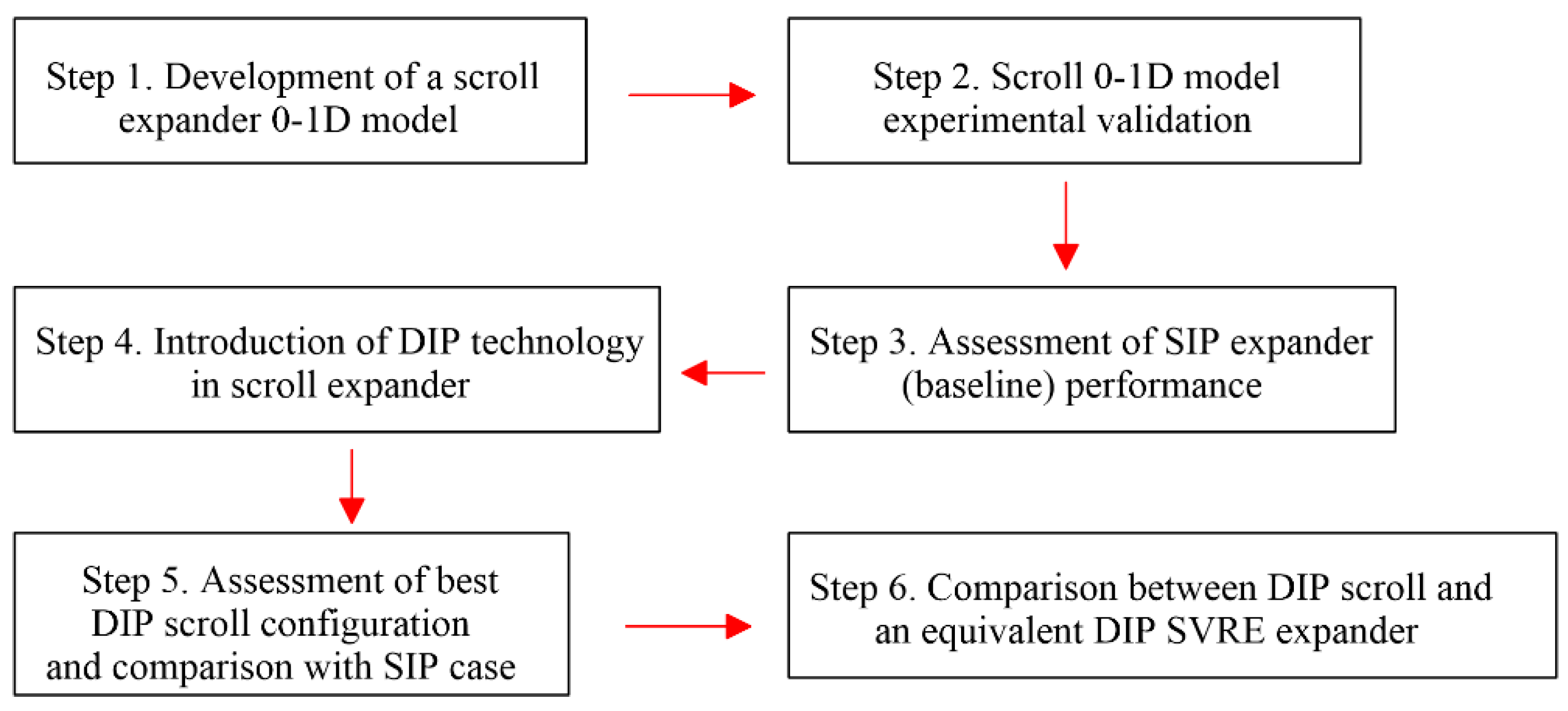
2. Materials and Methods
2.1. Case Study
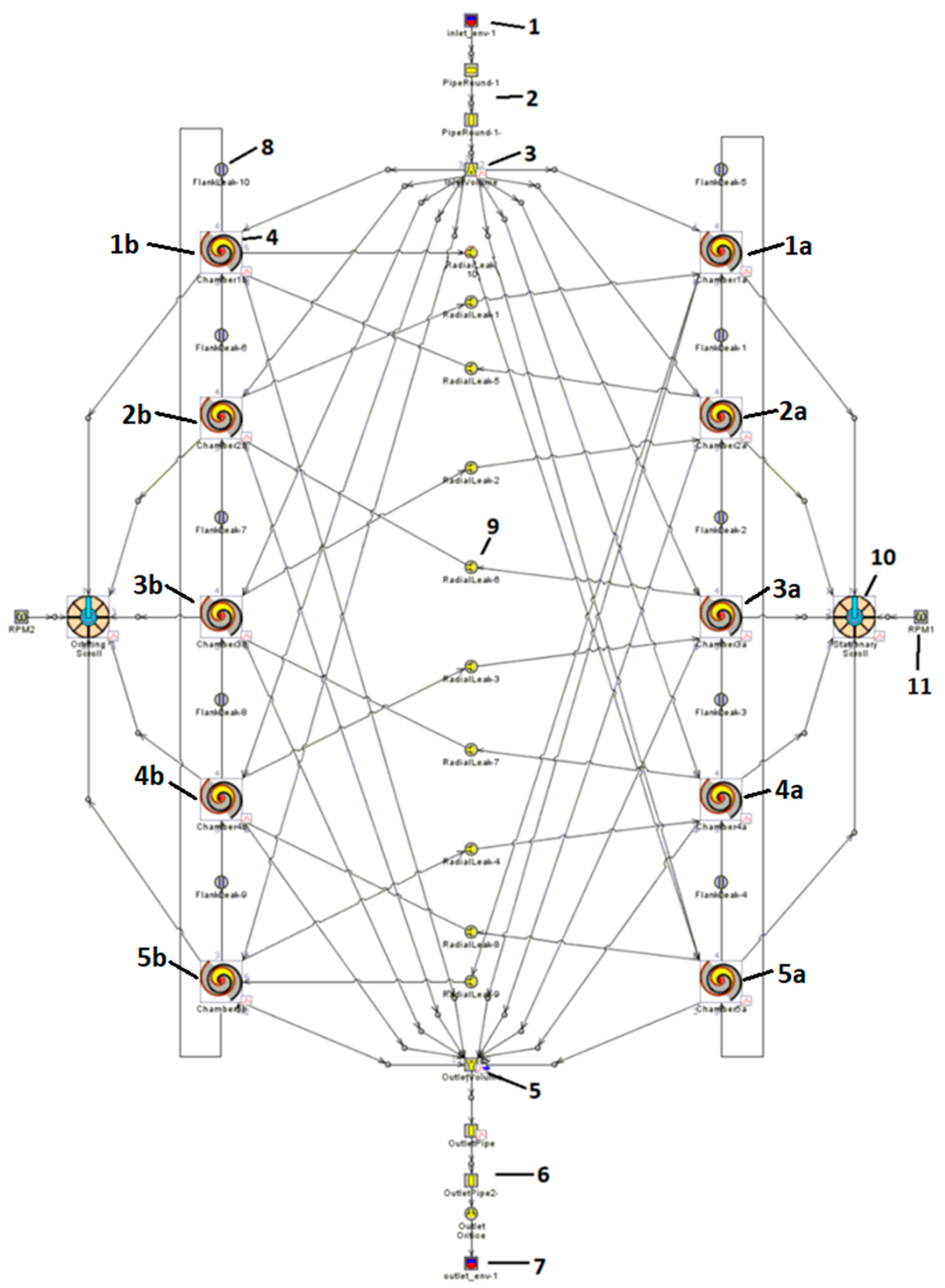
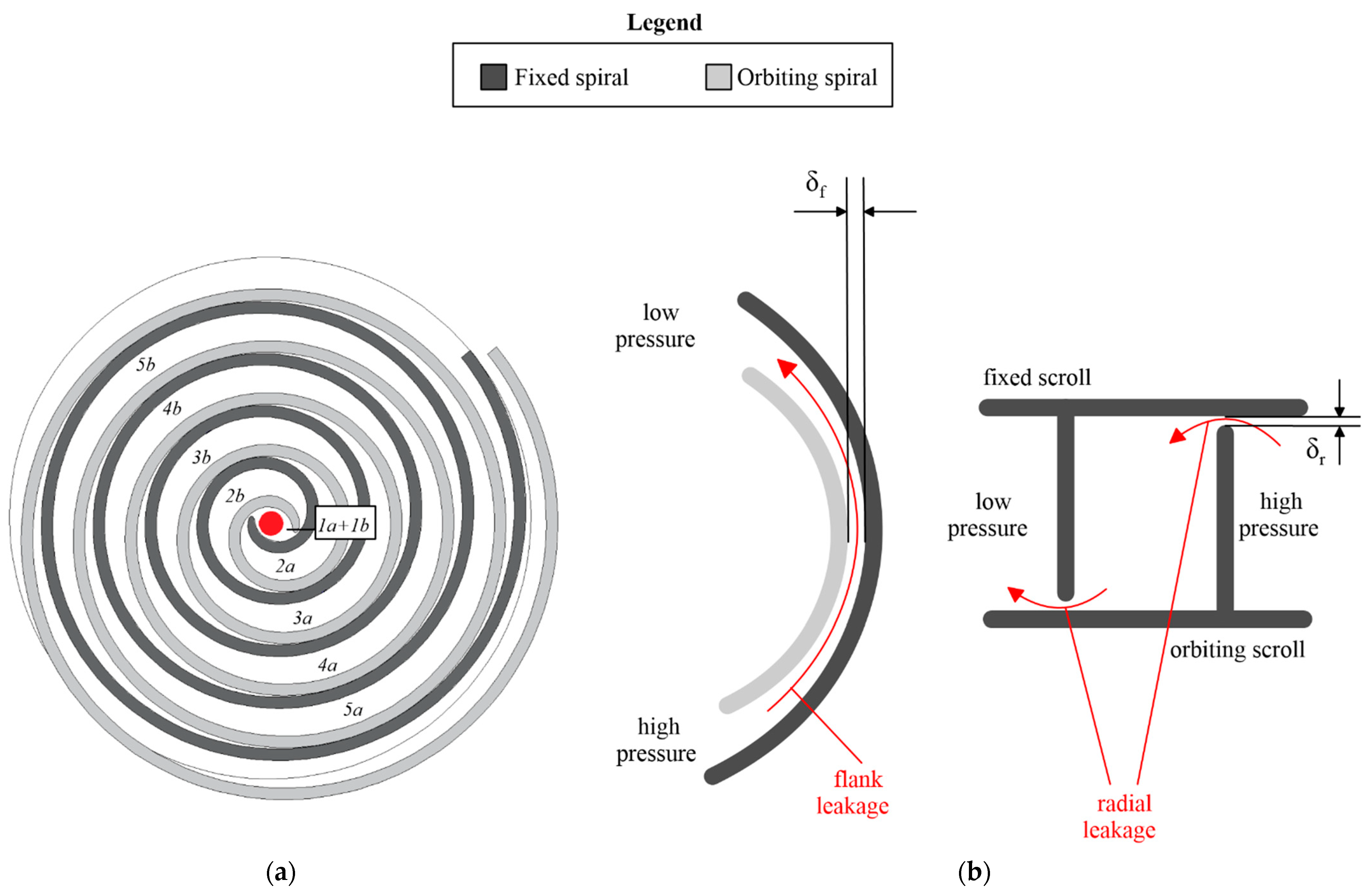
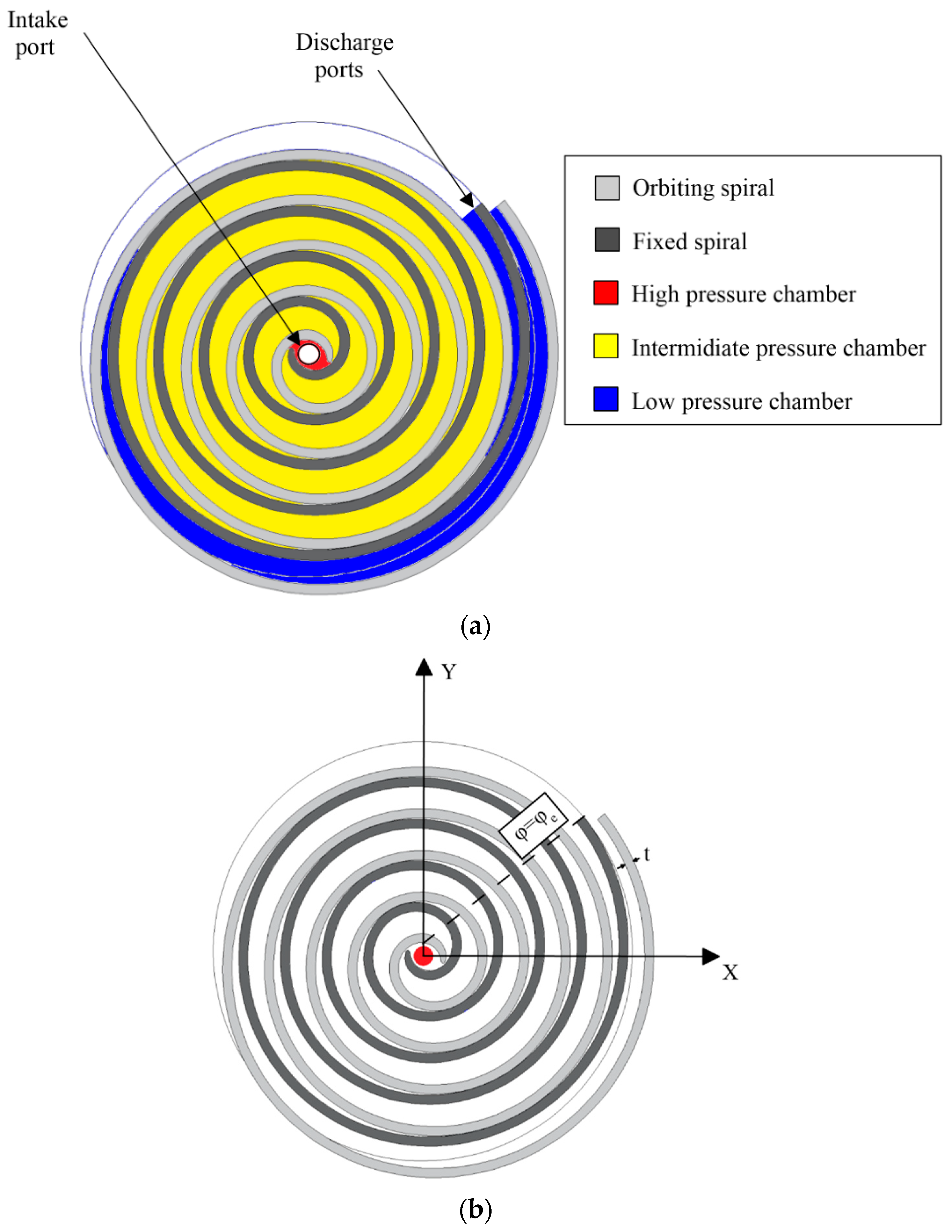
2.2. Numerical Model
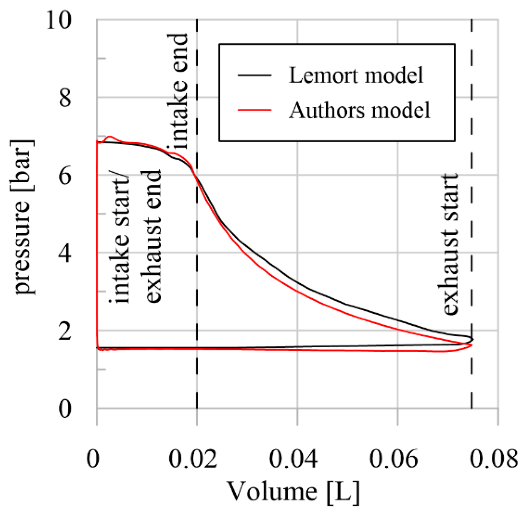
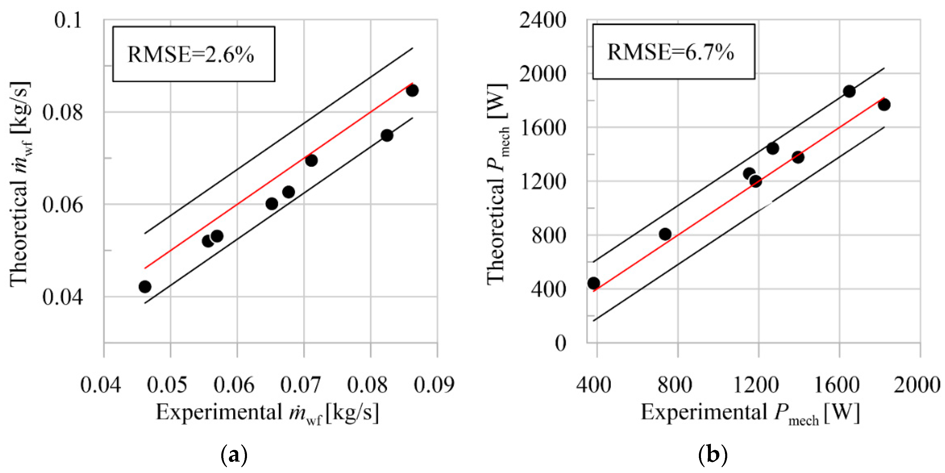
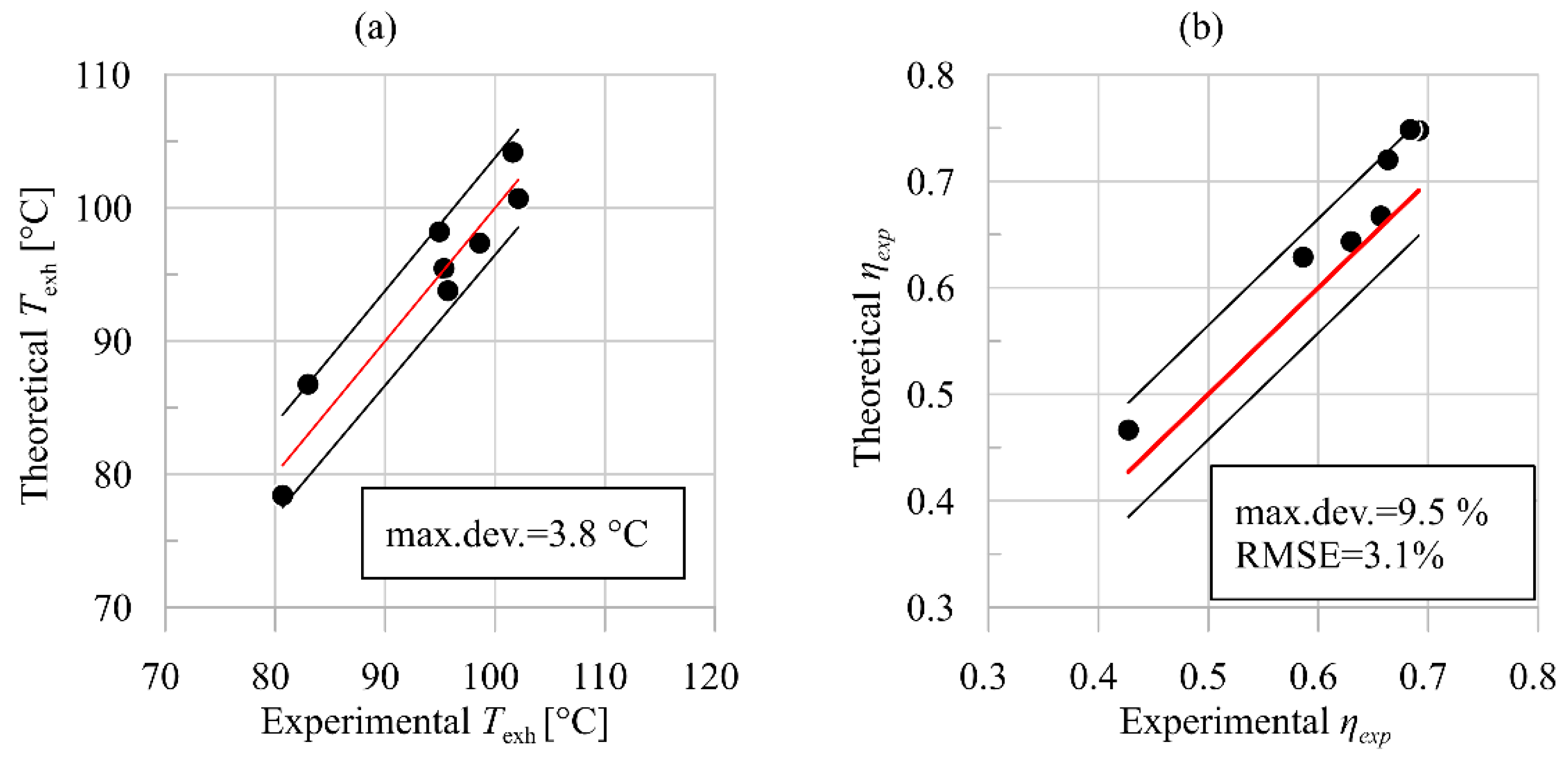
2.3. Validation
3. Results
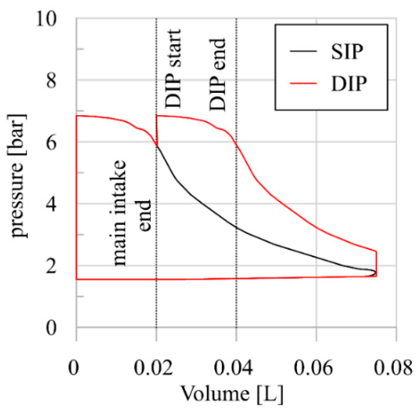
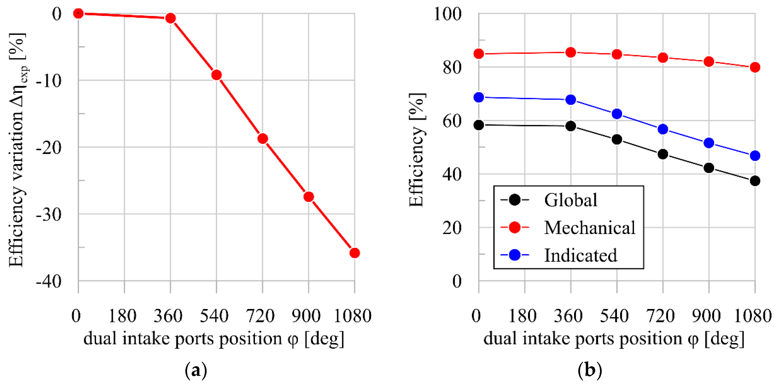
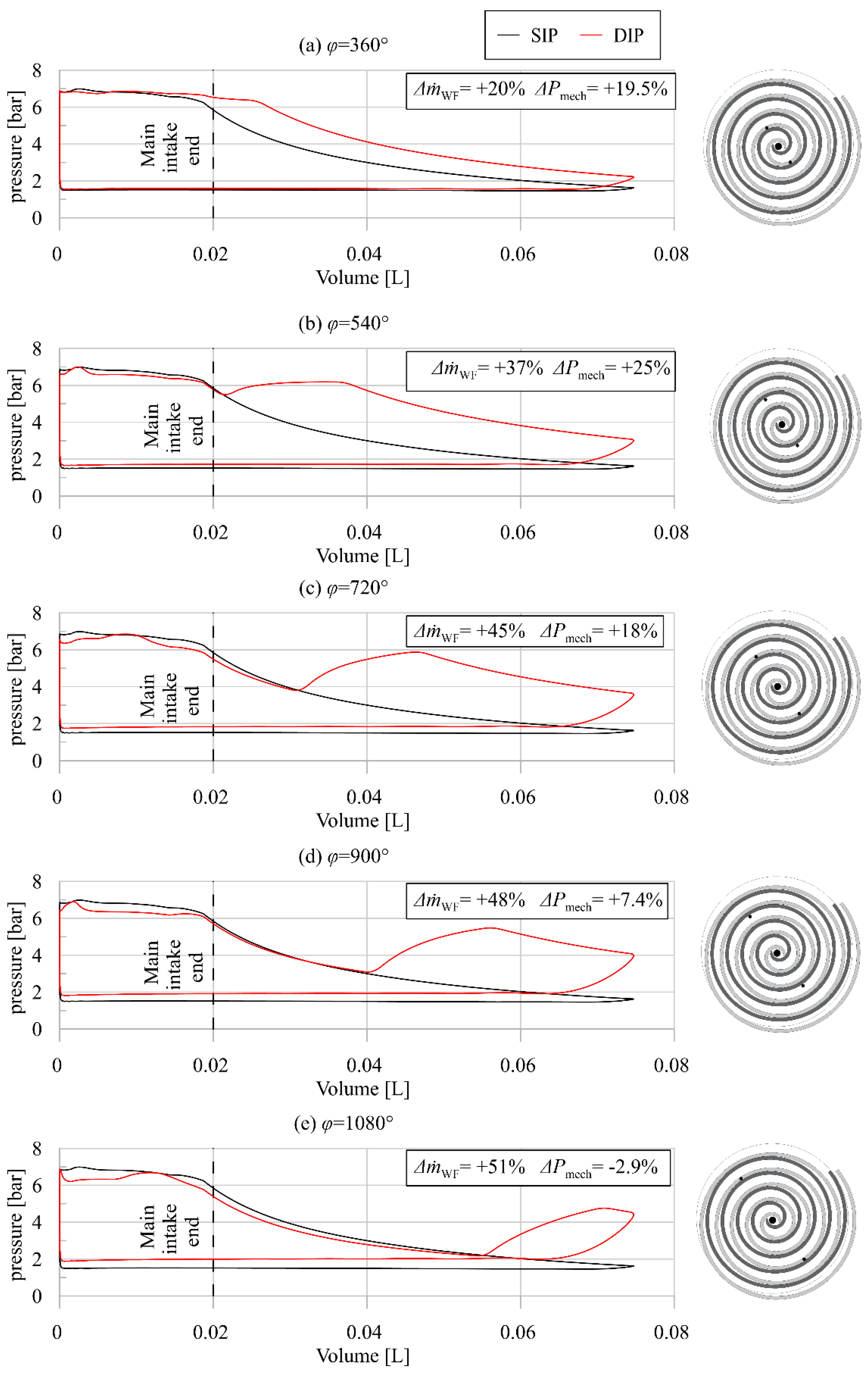
3.1. Feasibility Assessment of a DIP Technology for the Scroll Expander
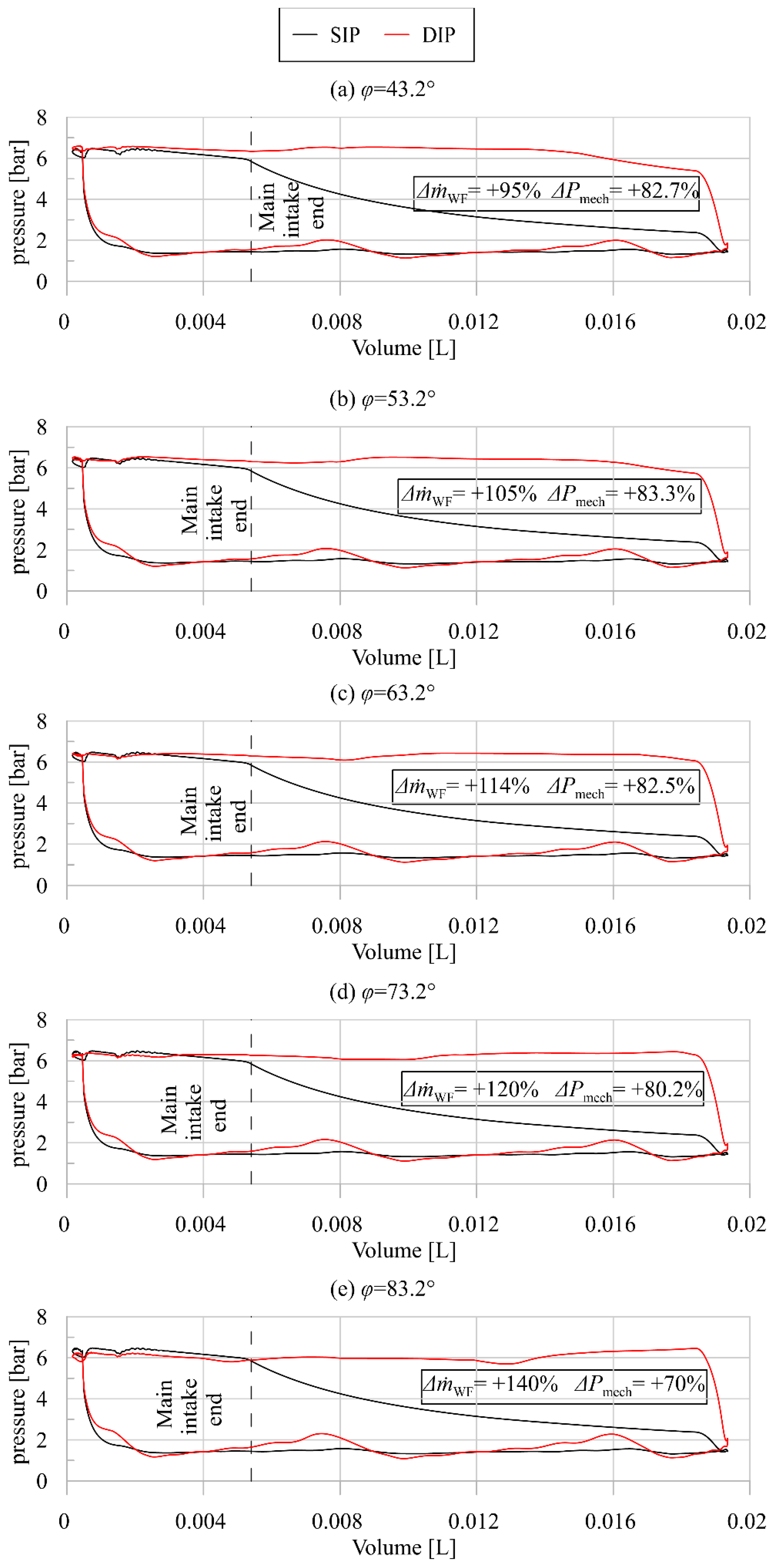
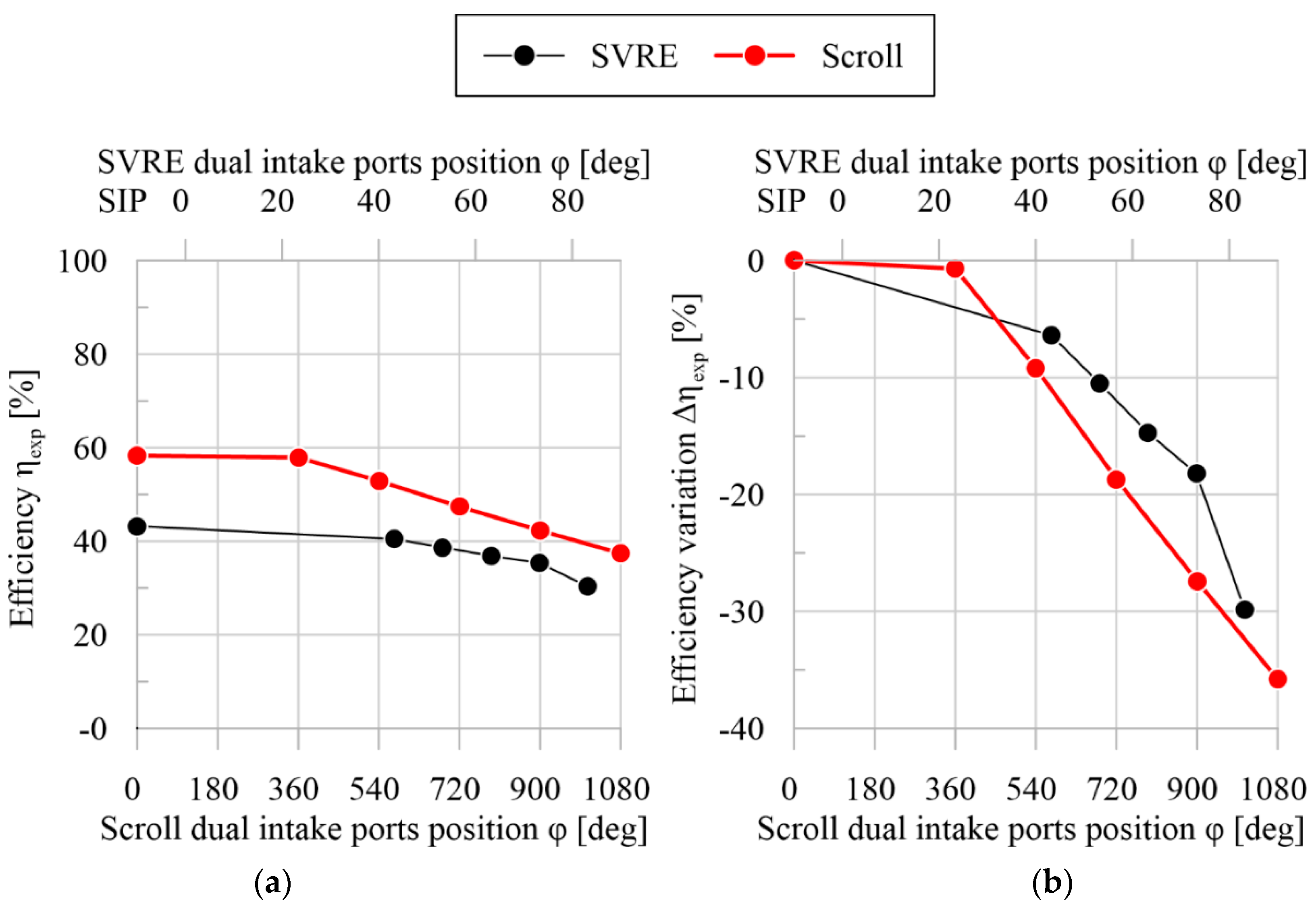
3.2. Comparison with DIP Technology for Sliding Rotary Vane Expander SVRE
- The first of these is the higher efficiency of the SIP Scroll (60%) when compared to the SVRE (43%).
- The second is that in the SVRE, the isochoric expansion at the end of the auxiliary intake phase is higher than in the case of the DIP Scroll. This is the effect of the higher extra mass flow rate on indicated power in the SVRE.
3.3. Discussion
- The efficiency of the SIP Scroll expander is higher than that of the SIP SVRE; the further improvement of 25% of the produced power of the DIP scroll expander is particularly appreciated. Indeed, the DIP technology shows a higher impact on the SVRE power because its original performance is lower than the Scroll expander. This can be seen when the best power configurations of the DIP SVRE (φ = 53.2°) and the DIP Scroll (φ = 540°) are observed. Both machines present a comparable power (1491 W for the SVRE and 1410 W for the Scroll), but the DIP Scroll reaches a higher efficiency than the SVRE (53% vs. 40%) (Table 4 and Table 6);
- Another factor which reinforces the suitability of the DIP technology for Scroll expanders is operability. Indeed, SIP scroll expanders are in general characterized by lower permeability compared to SIP SVREs. Thus, high-pressure ratios are achieved for the mass flow rate crossing the machines. With the introduction of the DIP technology, in the optimal configuration, the scroll expanders can elaborate 37% more mass flow rate with respect the SIP case, widening in this way the operating range of the machine and of the ORC plant.
4. Conclusions
Author Contributions
Funding
Institutional Review Board Statement
Informed Consent Statement
Data Availability Statement
Acknowledgments
Conflicts of Interest
Nomenclature
| Acronyms | |
| DIP | Dual intake port |
| HRVG | Heat recovery vapor generator |
| ICE | Internal combustion engine |
| RMSE | Root mean square error |
| SIP | Single intake port |
| SVRE | Sliding vane rotary expander |
| WHR | Waste heat recovery |
| Symbols | |
| Ft | Friction torque [Nm] |
| h | Specific enthalpy [kJ/kg] |
| Elaborated mass flow rate of working fluid [kg/s] | |
| Mass flow rate of working fluid entering the chamber [kg/s] | |
| Leakages mass flow rate [kg/s] | |
| nc | Number of scroll revolution in a cycle |
| P | Power [W] |
| p | Pressure [Pa], [bar] |
| T | Temperature [K]-[°C] |
| V | Chamber volume [cm3] |
| Subscripts | |
| cycle | rotation cycle |
| exp | expander global efficiency |
| in | inlet |
| ind | indicated |
| is | isentropic condition |
| loss | power loss due to friction |
| mech | mechanical |
| out | outlet |
| vol | volumetric |
| WF | working fluid |
| Greek symbols | |
| α | scroll permeability [kg/(s·MPa)] |
| η | efficiency |
| μ | dynamic viscosity [Pa·s] |
| θ | revolution angle [deg] |
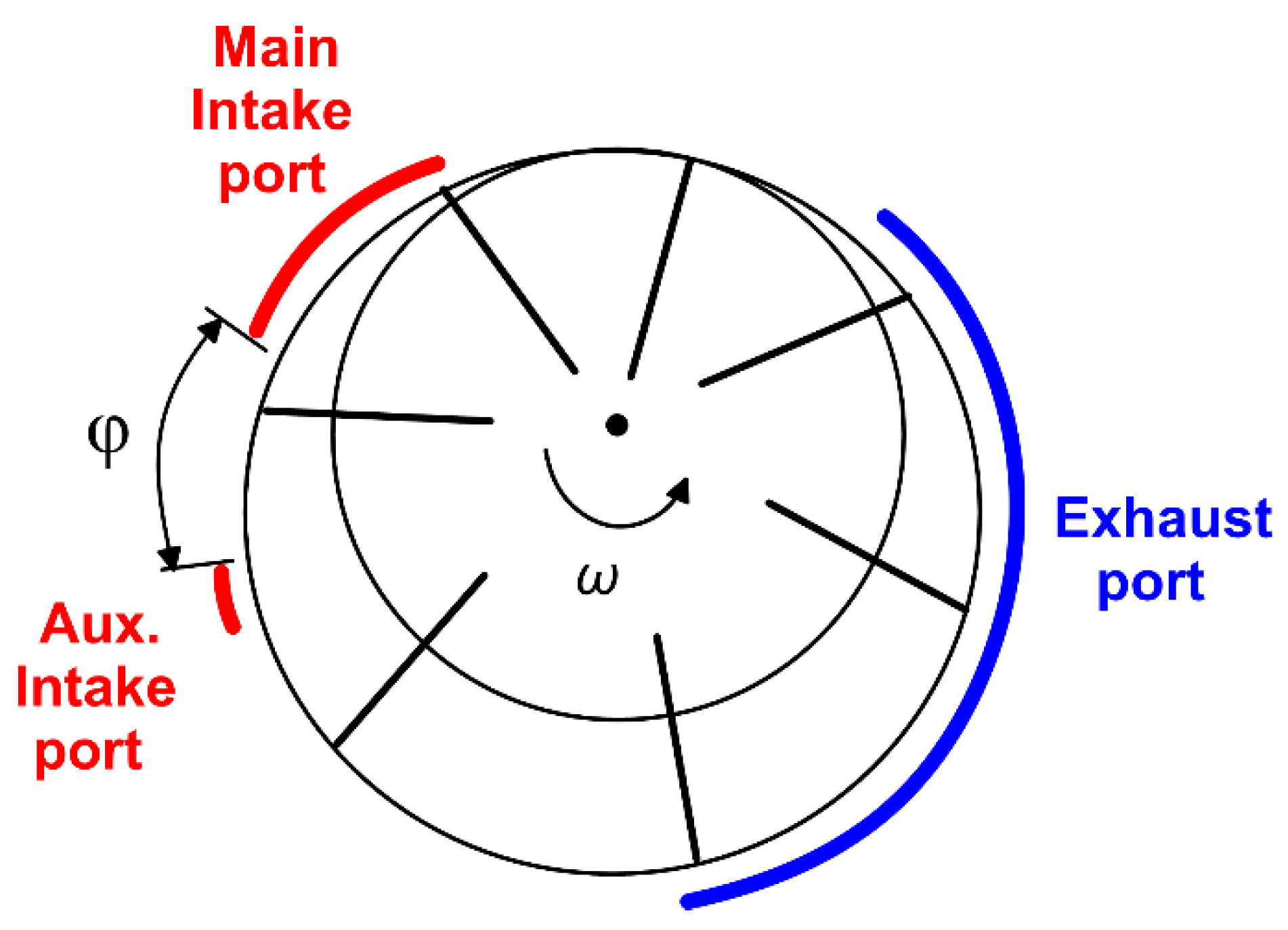
| φ | angular delay of DIP with respect main intake port [deg] |
| ω | revolution speed [RPM]-[RPS] |
References
- Transport Emissions. Available online: https://ec.europa.eu/clima/eu-action/transport-emissions_en (accessed on 16 November 2021).
- European Automobile Manufacturers’ Association (ACEA). Paving the Way to Carbon-Neutral Transport 10-Point Plan to Help Implement the European Green Deal. 2020. Available online: https://www.acea.auto/files/ACEA_10-point_plan_European_Green_Deal.pdf (accessed on 16 November 2021).
- European Union. Regulation (EU) 2019/631 of the European Parliament and of the Council. Off. J. Eur. Union 2019, 1–50. [Google Scholar]
- Serrano, J.R.; Novella, R.; Piqueras, P. Why the development of internal combustion engines is still necessary to fight against global climate change from the perspective of transportation. Appl. Sci. 2019, 9, 4597. [Google Scholar] [CrossRef] [Green Version]
- Seyedkavoosi, S.; Javan, S.; Kota, K. Exergy-based optimization of an organic Rankine cycle (ORC) for waste heat recovery from an internal combustion engine (ICE). Appl. Therm. Eng. 2017, 126, 447–457. [Google Scholar] [CrossRef]
- Song, J.; Li, X.; Wang, K.; Markides, C.N. Parametric optimisation of a combined supercritical CO2 (S-CO2) cycle and organic Rankine cycle (ORC) system for internal combustion engine (ICE) waste-heat recovery. Energy Convers. Manag. 2020, 218, 112999. [Google Scholar] [CrossRef]
- Shi, L.; Shu, G.; Tian, H.; Deng, S. A review of modified Organic Rankine cycles (ORCs) for internal combustion engine waste heat recovery (ICE-WHR). Renew. Sustain. Energy Rev. 2018, 92, 95–110. [Google Scholar] [CrossRef]
- Di Battista, D.; Di Bartolomeo, M.; Villante, C.; Cipollone, R. On the limiting factors of the waste heat recovery via ORC-based power units for on-the-road transportation sector. Energy Convers. Manag. 2018, 155, 68–77. [Google Scholar] [CrossRef]
- Chatzopoulou, M.A.; Simpson, M.; Sapin, P.; Markides, C.N. Off-design optimisation of organic Rankine cycle (ORC) engines with piston expanders for medium-scale combined heat and power applications. Appl. Energy 2019, 238, 1211–1236. [Google Scholar] [CrossRef]
- Marchionni, M.; Bianchi, G.; Karvountzis-Kontakiotis, A.; Pesyridis, A.; Tassou, S.A. An appraisal of proportional integral control strategies for small scale waste heat to power conversion units based on Organic Rankine Cycles. Energy 2018, 163, 1062–1076. [Google Scholar] [CrossRef]
- Chatzopoulou, M.A.; Lecompte, S.; de Paepe, M.; Markides, C.N. Off-design optimisation of organic Rankine cycle (ORC) engines with different heat exchangers and volumetric expanders in waste heat recovery applications. Appl. Energy 2019, 253, 113442. [Google Scholar] [CrossRef]
- Moradi, R.; Villarini, M.; Cioccolanti, L. Experimental modeling of a lubricated, open drive scroll expander for micro-scale organic Rankine cycle systems. Appl. Therm. Eng. 2021, 190, 116784. [Google Scholar] [CrossRef]
- Pantano, F.; Capata, R. Expander selection for an on board ORC energy recovery system. Energy 2017, 141, 1084–1096. [Google Scholar] [CrossRef] [Green Version]
- Dumont, O.; Parthoens, A.; Dickes, R.; Lemort, V. Experimental investigation and optimal performance assessment of four volumetric expanders (scroll, screw, piston and roots) tested in a small-scale organic Rankine cycle system. Energy 2018, 165, 1119–1127. [Google Scholar] [CrossRef] [Green Version]
- Bao, J.; Zhao, L. A review of working fluid and expander selections for organic Rankine cycle. Renew. Sustain. Energy Rev. 2013, 24, 325–342. [Google Scholar] [CrossRef]
- Imran, M.; Usman, M.; Park, B.S.; Lee, D.H. Volumetric expanders for low grade heat and waste heat recovery applications. Renew. Sustain. Energy Rev. 2016, 57, 1090–1109. [Google Scholar] [CrossRef]
- Song, P.; Wei, M.; Shi, L.; Danish, S.N.; Ma, C. A review of scroll expanders for organic rankine cycle systems. Appl. Therm. Eng. 2015, 75, 54–64. [Google Scholar] [CrossRef]
- Chang, J.C.; Chang, C.W.; Hung, T.C.; Lin, J.R.; Huang, K.C. Experimental study and CFD approach for scroll type expander used in low-temperature organic Rankine cycle. Appl. Therm. Eng. 2014, 73, 1444–1452. [Google Scholar] [CrossRef]
- Emhardt, S.; Tian, G.; Song, P.; Chew, J.; Wei, M. CFD modelling of small scale ORC scroll expanders using variable wall thicknesses. Energy 2020, 199, 117399. [Google Scholar] [CrossRef] [Green Version]
- Zhang, X.; Xu, Y.; Xu, J.; Sheng, Y.; Zuo, Z.; Liu, J.; Chen, H.; Wang, Y.; Huang, Y. Study on the performance and optimization of a scroll expander driven by compressed air. Appl. Energy 2017, 186, 347–358. [Google Scholar] [CrossRef]
- Lemort, V.; Quoilin, S.; Cuevas, C.; Lebrun, J. Testing and modeling a scroll expander integrated into an Organic Rankine Cycle. Appl. Therm. Eng. 2009, 29, 3094–3102. [Google Scholar] [CrossRef] [Green Version]
- Kutlu, C.; Erdinc, M.T.; Li, J.; Su, Y.; Pei, G.; Gao, G.; Riffat, S. Evaluate the validity of the empirical correlations of clearance and friction coefficients to improve a scroll expander semi-empirical model. Energy 2020, 202, 117723. [Google Scholar] [CrossRef]
- Song, P.; Wei, M.; Zhang, Y.; Sun, L.; Emhardt, S.; Zhuge, W. The impact of a bilateral symmetric discharge structure on the performance of a scroll expander for ORC power generation system. Energy 2018, 158, 458–470. [Google Scholar] [CrossRef]
- Kosmadakis, G.; Mousmoulis, G.; Manolakos, D.; Anagnostopoulos, I.; Papadakis, G.; Papantonis, D. Development of Open-Drive Scroll Expander for an Organic Rankine Cycle (ORC) Engine and First Test Results. Energy Procedia 2017, 129, 371–378. [Google Scholar] [CrossRef]
- Ziviani, D.; James, N.A.; Accorsi, F.A.; Braun, J.E.; Groll, E.A. Experimental and numerical analyses of a 5 kWe oil-free open-drive scroll expander for small-scale organic Rankine cycle (ORC) applications. Appl. Energy 2018, 230, 1140–1156. [Google Scholar] [CrossRef]
- Garg, P.; Karthik, G.M.; Kumar, P.; Kumar, P. Development of a generic tool to design scroll expanders for ORC applications. Appl. Therm. Eng. 2016, 109, 878–888. [Google Scholar] [CrossRef] [Green Version]
- Yang, J.; Sun, Z.; Yu, B.; Chen, J. Modeling and optimization criteria of scroll expander integrated into organic Rankine cycle for comparison of R1233zd(E) as an alternative to R245fa. Appl. Therm. Eng. 2018, 141, 386–393. [Google Scholar] [CrossRef]
- Emhardt, S.; Tian, G.; Chew, J. A review of scroll expander geometries and their performance. Appl. Therm. Eng. 2018, 141, 1020–1034. [Google Scholar] [CrossRef]
- Emhardt, S.; Tian, G.; Song, P.; Chew, J.; Wei, M. CFD analysis of the influence of variable wall thickness on the aerodynamic performance of small scale ORC scroll expanders. Energy 2021, 122586. [Google Scholar] [CrossRef]
- Emhardt, S.; Song, P.; Tian, G.; Chew, J.; Wei, M. CFD analysis of variable wall thickness scroll expander integrated into small scale ORC systems. Energy Procedia 2019, 158, 2272–2277. [Google Scholar] [CrossRef]
- Fatigati, F.; Di Bartolomeo, M.; Cipollone, R. Dual intake rotary vane expander technology: Experimental and theoretical assessment. Energy Convers. Manag. 2019, 186, 156–167. [Google Scholar] [CrossRef]
- Fatigati, F.; Di Bartolomeo, M.; Di Battista, D.; Cipollone, R. A dual-intake-port technology as a design option for a Sliding Vane Rotary Expander of small-scale ORC-based power units. Energy Convers. Manag. 2020, 209, 112646. [Google Scholar] [CrossRef]
- Fatigati, F.; Di Giovine, G.; Cipollone, R. Model-based characterization of a dual intake-port scroll expander operating in an ORC-based power unit. In Proceedings of the 16th Conference on Sustainable Development of Energy, Water and Environment Systems, Dubrovnik, Croatia, 10–15 October 2021; pp. 1–21. [Google Scholar]
- Mudrovčić, A.; Ban, M. Book of Abstracts—16th Conference on Sustainable Development of Energy, Water and Environment Systems; Faculty of Mechanical Engineering and Naval Architecture, Zagreb: Dubrovnik, Croatia, 2021. [Google Scholar]
- Lemort, V. Contribution to the Characterization of Scroll Machines in Compressor and Expander Modes. Ph.D. Thesis, University of Liège, Liège, Belgium, 2008. [Google Scholar]
- Chen, Y.; Halm, N.P.; Groll, E.A.; Braun, J.E. Mathematical modeling of scroll compressors—Part I: Compression process modeling. Int. J. Refrig. 2002, 25, 731–750. [Google Scholar] [CrossRef]
- Chen, Y.C.; Halm, N.P.; Braun, J.E.; Groll, E.A. Mathematical modeling of scroll compressors—Part II: Overall scroll compressor modeling. Int. J. Refrig. 2002, 25, 751–764. [Google Scholar] [CrossRef]
- Sun, S.; Wu, K.; Guo, P.; Yan, J. Analysis of the three-dimensional transient flow in a scroll refrigeration compressor. Appl. Therm. Eng. 2017, 127, 1086–1094. [Google Scholar] [CrossRef]
- Quoilin, S.; Lemort, V.; Lebrun, J. Experimental study and modeling of an Organic Rankine Cycle using scroll expander. Appl. Energy 2010, 87, 1260–1268. [Google Scholar] [CrossRef]
- Gamma Technologies. Flow Theory Manual—GT-SUITE™. 2012. Available online: https://www.gtisoft.com/ (accessed on 8 December 2021).


| Description | Abbreviation | Value | Unit of Measurement |
|---|---|---|---|
| Radius of the basic circle of the scroll | 3.3 | [mm] | |
| Heigh of scroll vanes | 28.7 | [mm] | |
| Initial angle of the outer involute | 0 | [rad] | |
| Initial angle of the inner involute | 1.4 | [rad] | |
| Starting angle of the outer involute | 1.6 | [rad] | |
| Starting angle of the inner involute | 3.5 | [rad] | |
| Involute ending angle | 27.4 | [rad] | |
| Orbiting radius of the rotating scroll | 5.7 | [mm] | |
| Scroll vane thickness | 4.6 | [mm] | |
| Discharge angle | 3.9 | [rad] |
| Case | 1 | 2 | 3 | 4 | 5 | 6 | 7 |
|---|---|---|---|---|---|---|---|
| pin [bar] | 6.4 | 5.5 | 8.1 | 8.9 | 11.1 | 7.9 | 9.6 |
| Tin [°C] | 109.8 | 121.0 | 136.5 | 130.3 | 141.2 | 132.5 | 138.9 |
| pout [bar] | 1.9 | 2.0 | 2.1 | 1.7 | 2.0 | 1.8 | 2.1 |
| Tout [°C] | 80.7 | 94.9 | 102.1 | 83.0 | 95.3 | 95.7 | 98.6 |
| [kg/s] | 0.057 | 0.046 | 0.068 | 0.065 | 0.082 | 0.071 | 0.086 |
| Pm [W] | 737 | 382 | 1184 | 1394 | 1820 | 1269 | 1648 |
| ω [rpm] | 2296 | 2295 | 2296 | 1771 | 1771 | 2660 | 2660 |
| ηvol | 0.86 | 0.84 | 0.84 | 0.78 | 0.77 | 0.92 | 0.93 |
| ηexp | 0.59 | 0.43 | 0.66 | 0.69 | 0.68 | 0.63 | 0.66 |
| Parameter | Value | Unit of Measurement |
|---|---|---|
| Flank leakage gap | 46 | |
| Flank leakage length | 25 | mm |
| Tip radial leakage area | 7 | |
| Friction torque FT | 2.5 | Nm |
| Case | SIP | φ = 360° | φ = 540° | φ = 720° | φ = 900° | φ = 1080° |
|---|---|---|---|---|---|---|
| [kg/s] | 0.059 | 0.071 | 0.081 | 0.085 | 0.087 | 0.089 |
| Pmech [W] | 1131 | 1352 | 1410 | 1333 | 1216 | 1098 |
| ηexp [%] | 58.3 | 57.9 | 52.9 | 47.4 | 42.3 | 37.4 |
| Δ [%] | 0.0 | 20 | 37 | 45 | 48 | 51 |
| ΔPmech [%] | 0.0 | 19.5 | 25 | 18 | 7.4 | −2.9 |
| Δηexp [%] | 0.0 | −0.7 | −9.2 | −18.7 | −27.4 | −35.8 |
| Description | Value | Unit of Measurement |
|---|---|---|
| Stator diameter | 75.9 | [mm] |
| Rotor diameter | 65 | [mm] |
| Eccentricity | 5.45 | [mm] |
| Expander width | 60 | [mm] |
| Blade thickness | 3.96 | [mm] |
| Blade length | 17 | [mm] |
| Intake port opening angle | 4.4 | [deg] |
| Intake port closing angle | 48 | [deg] |
| Exhaust port opening angle | 180 | [deg] |
| Exhaust port closing angle | 322 | [deg] |
| Angular extent of the auxiliar intake port | 10.6 | [deg] |
| Rated revolution speed | 1500 | [RPM] |
| Case | SIP | φ = 43.2° | φ = 53.2° | φ = 63.2° | φ = 73.2° | φ = 83.2° |
|---|---|---|---|---|---|---|
| [kg/s] | 0.06 | 0.11 | 0.12 | 0.12 | 0.13 | 0.14 |
| Pmech [W] | 816 | 1491 | 1496 | 1489 | 1471 | 1392 |
| ηexp [%] | 43 | 40 | 39 | 37 | 35 | 30 |
| Δ [%] | 0.0 | 95.2 | 104.9 | 114.0 | 120.4 | 143.2 |
| ΔPmech [%] | 0.0 | 82.7 | 83.3 | 82.5 | 80.2 | 70.6 |
| Δηexp [%] | 0.0 | −6.4 | −10.5 | −14.7 | −18.2 | −29.9 |
Publisher’s Note: MDPI stays neutral with regard to jurisdictional claims in published maps and institutional affiliations. |
© 2022 by the authors. Licensee MDPI, Basel, Switzerland. This article is an open access article distributed under the terms and conditions of the Creative Commons Attribution (CC BY) license (https://creativecommons.org/licenses/by/4.0/).
Share and Cite
Fatigati, F.; Di Giovine, G.; Cipollone, R. Feasibility Assessment of a Dual Intake-Port Scroll Expander Operating in an ORC-Based Power Unit. Energies 2022, 15, 770. https://doi.org/10.3390/en15030770
Fatigati F, Di Giovine G, Cipollone R. Feasibility Assessment of a Dual Intake-Port Scroll Expander Operating in an ORC-Based Power Unit. Energies. 2022; 15(3):770. https://doi.org/10.3390/en15030770
Chicago/Turabian StyleFatigati, Fabio, Giammarco Di Giovine, and Roberto Cipollone. 2022. "Feasibility Assessment of a Dual Intake-Port Scroll Expander Operating in an ORC-Based Power Unit" Energies 15, no. 3: 770. https://doi.org/10.3390/en15030770
APA StyleFatigati, F., Di Giovine, G., & Cipollone, R. (2022). Feasibility Assessment of a Dual Intake-Port Scroll Expander Operating in an ORC-Based Power Unit. Energies, 15(3), 770. https://doi.org/10.3390/en15030770