
Experimental Studies of Low-Load Limit in a Stoichiometric Micro-Pilot Diesel Natural Gas Engine

 ,
,  ,
,  and
and 
Abstract
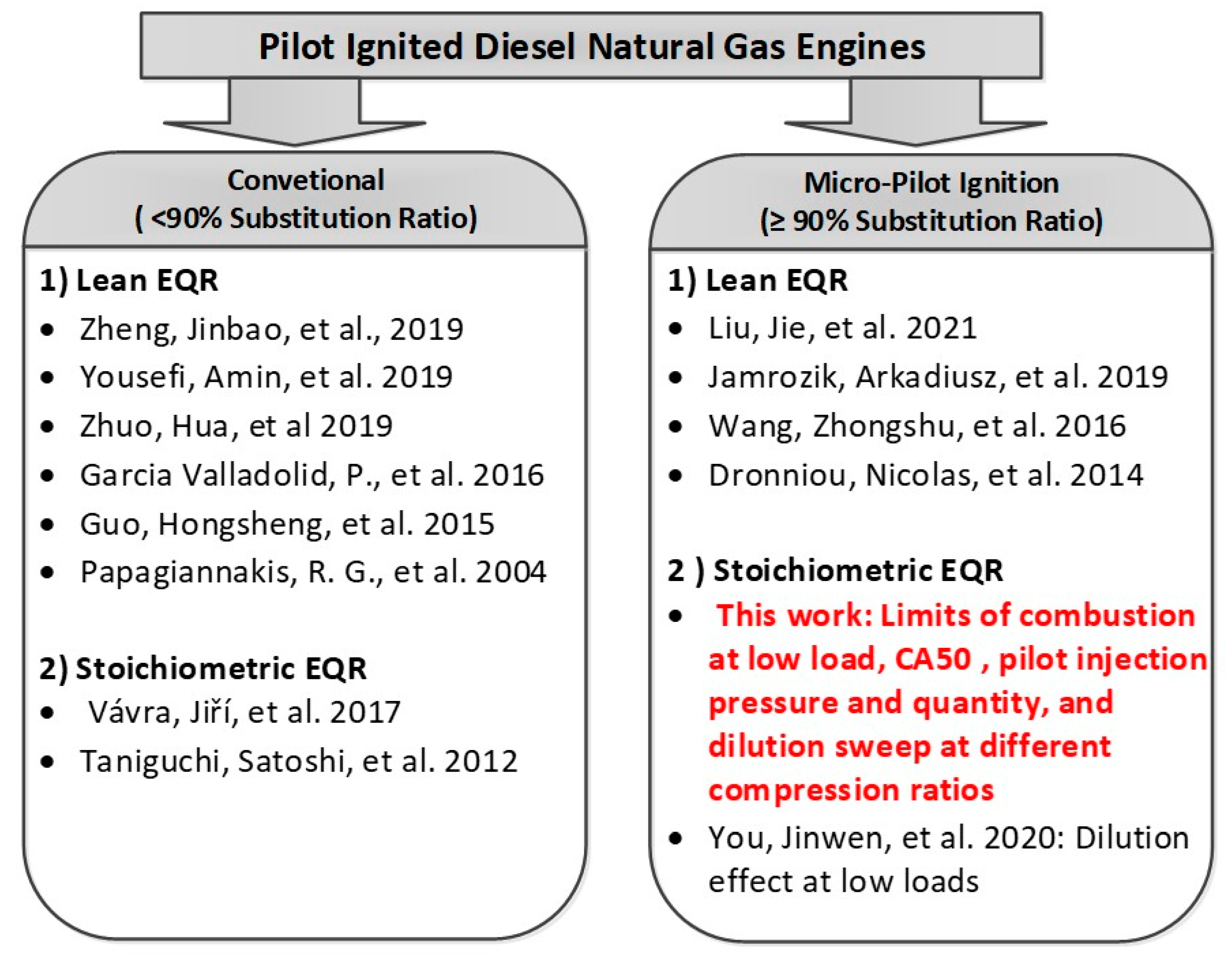
:1. Introduction
2. Materials and Methods
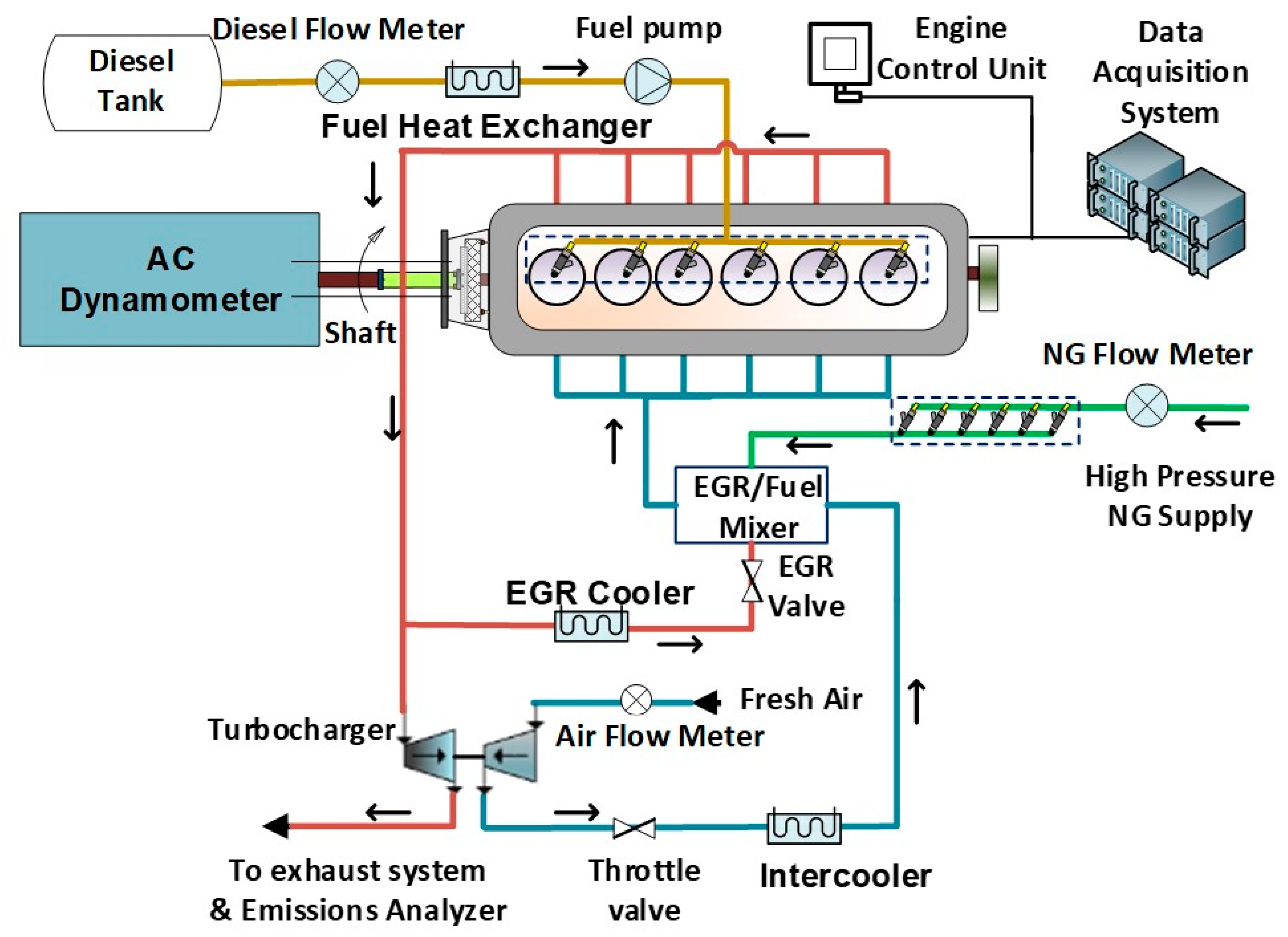
2.1. Micro-Pilot Diesel Natural Gas Engine
2.2. Instrumentation and Measurement Uncertainty
2.3. Fuels
2.4. Experimental Procedure
3. Results and Discussion
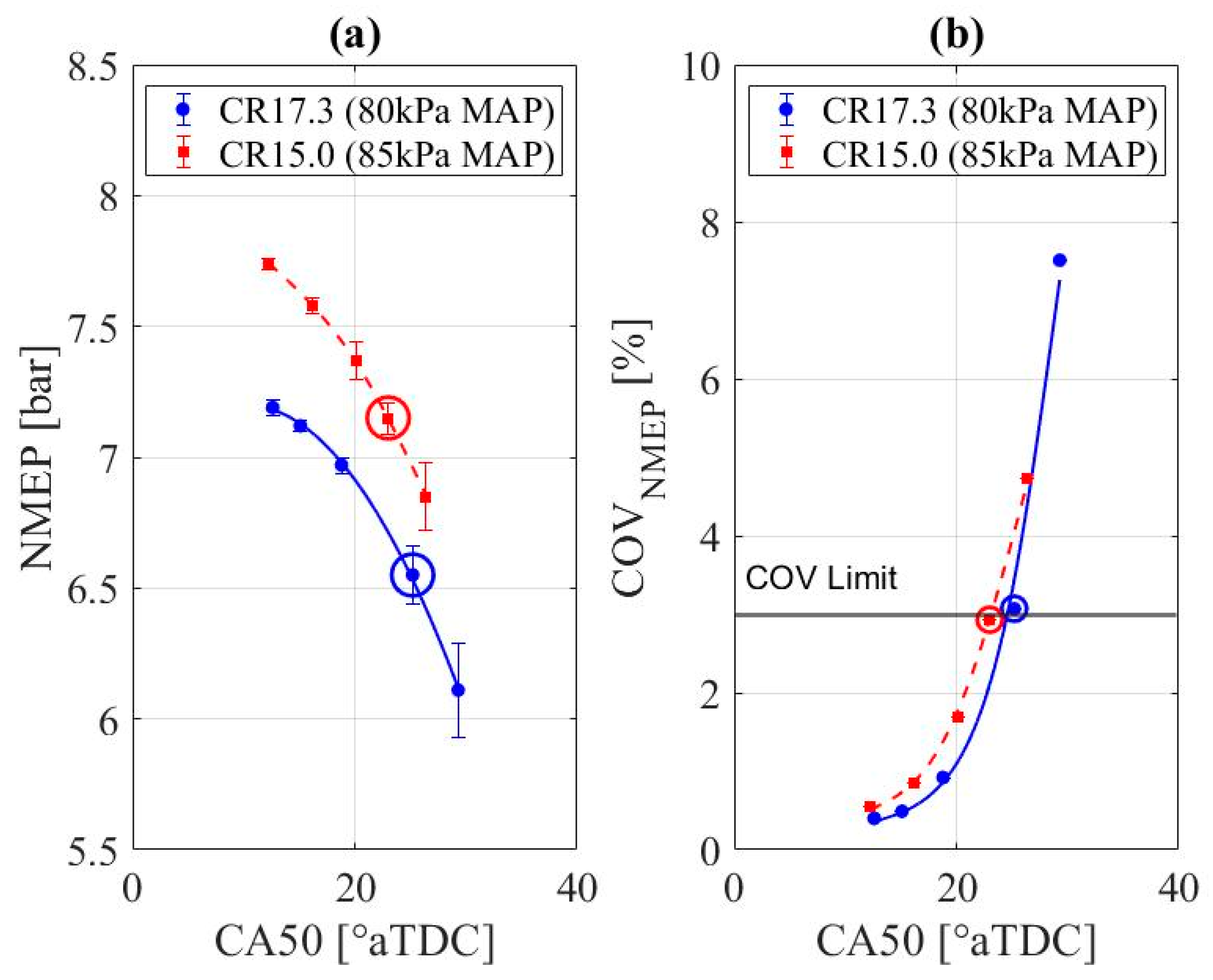
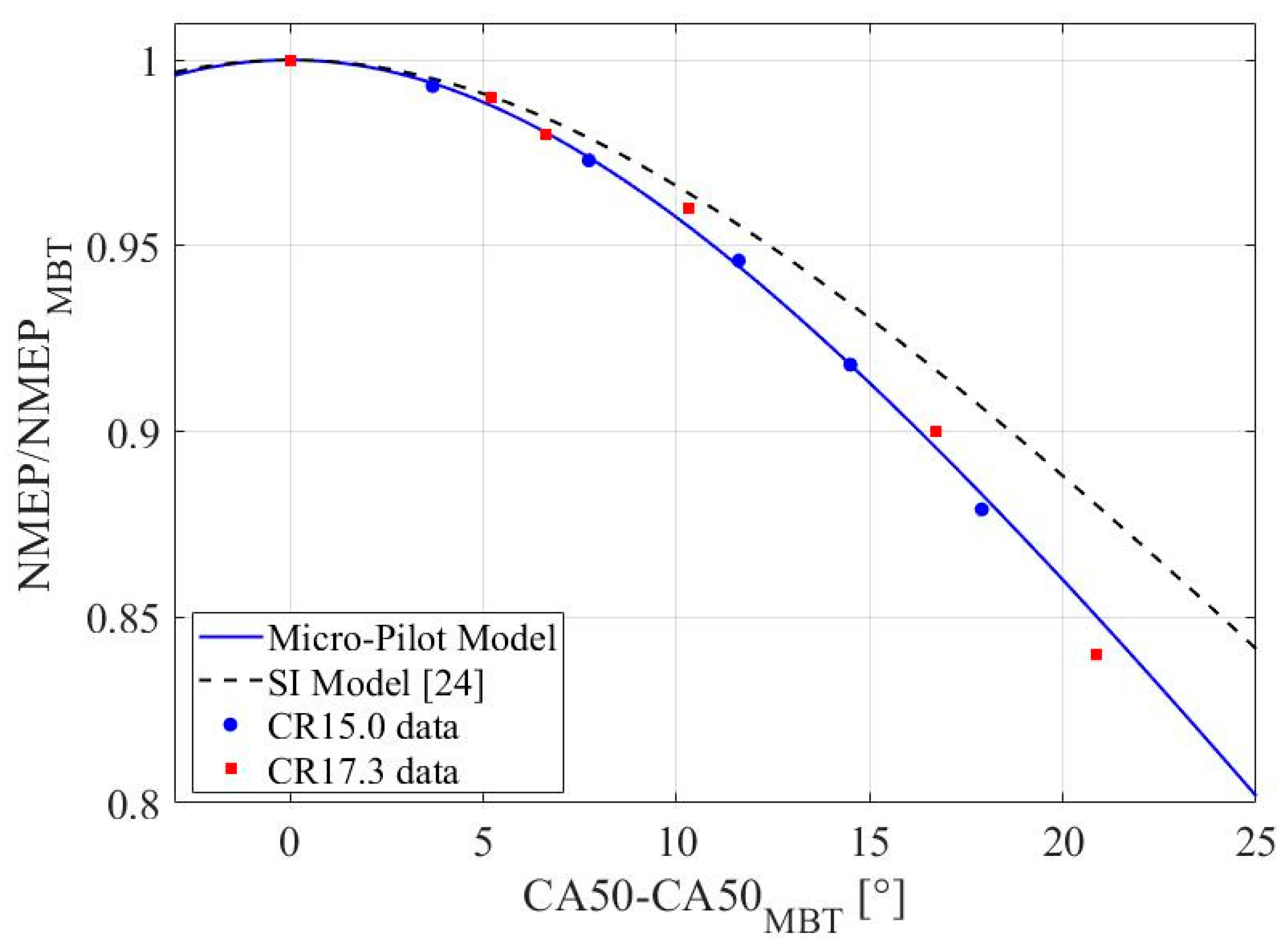
3.1. CA50 Study
- The higher compression ratio of the micro-pilot engine vs. the SI engine;
- Different combustion chamber geometries;
- Natural gas premix flame speed versus gasoline premix flame speed.
3.2. Diesel Injection Pressure Study
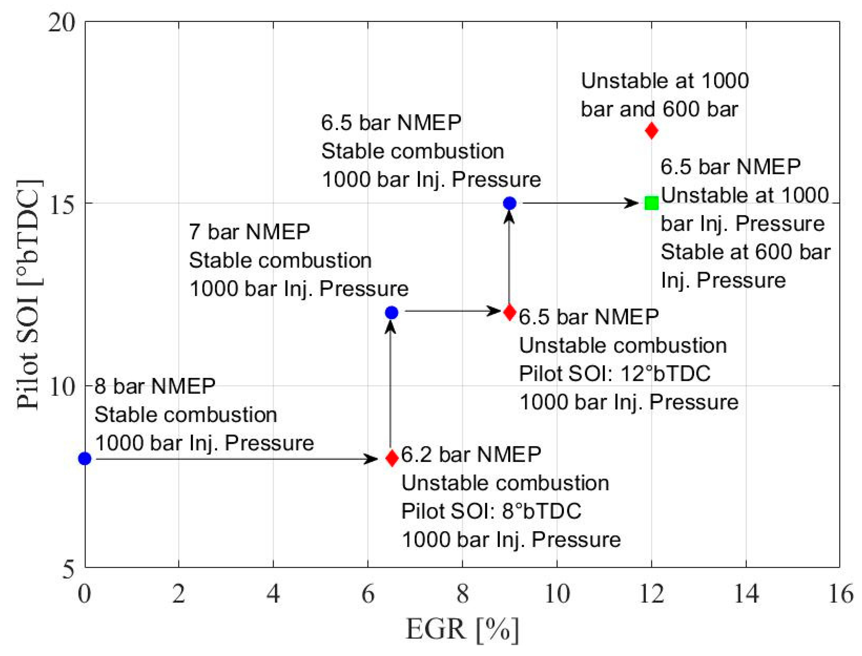
3.3. EGR Study
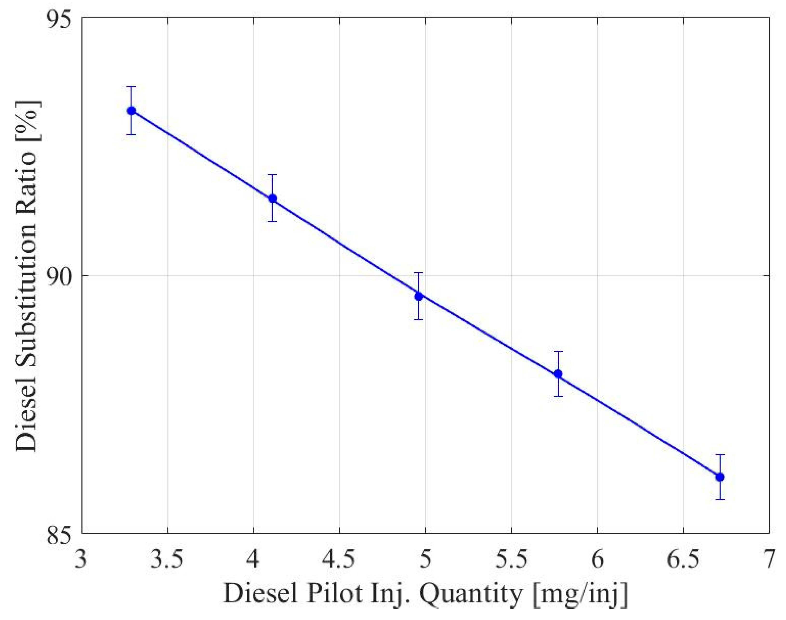
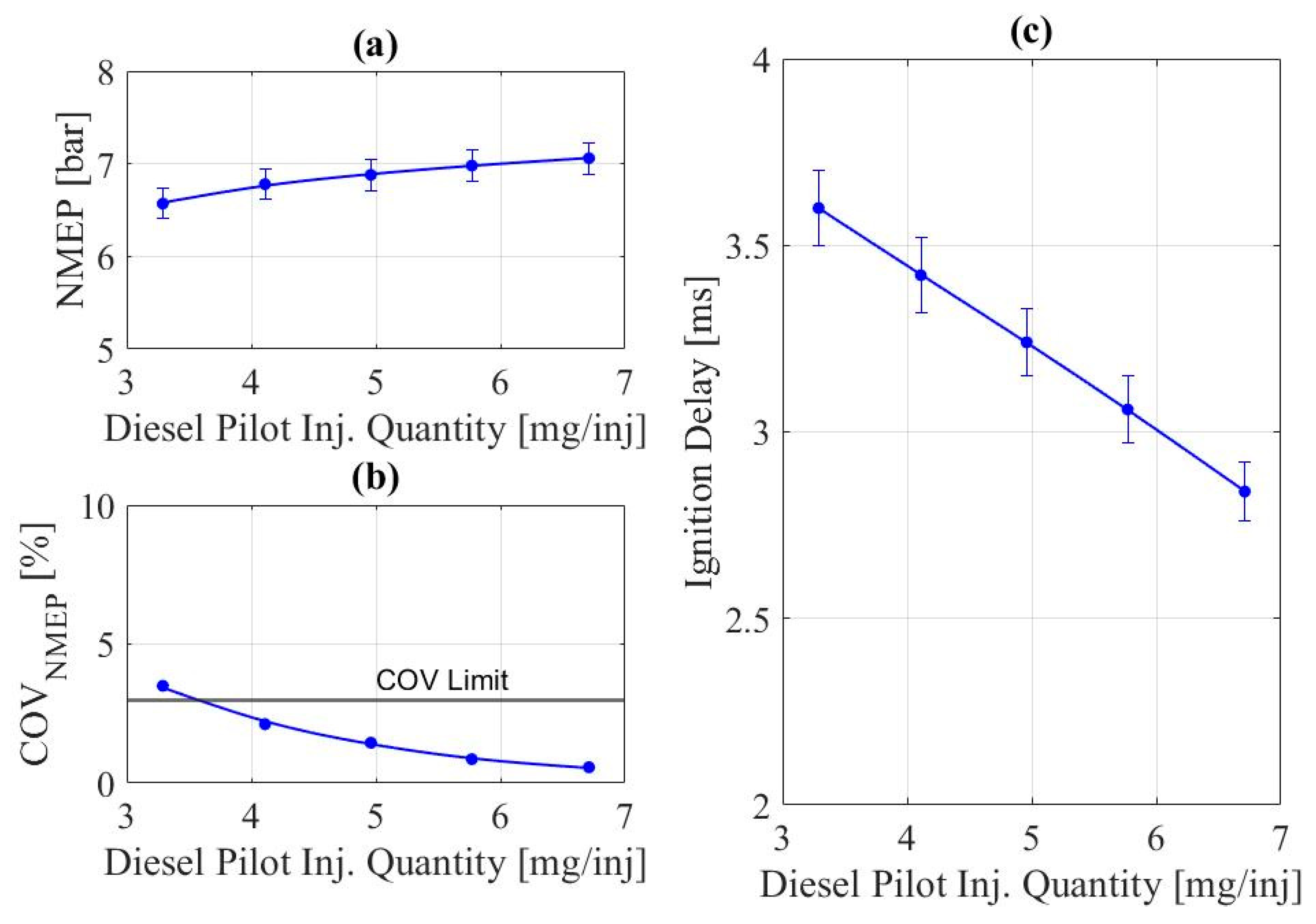
3.4. Diesel Pilot Injection Quantity Study
3.5. Lowest Stable Load Achievable in Stoichiometric Operation
4. Summary and Conclusions
- The compression ratio impacts the minimum intake manifold pressure that maintains combustion stable. By reducing the compression ratio from 17.3:1 to 15.0:1, the intake manifold pressure had to be increased by 5 kPa, which raised the lowest load achievable by 1 bar NMEP due to the extra premix fuel required to maintain a globally stoichiometric premix.
- Combustion phasing retard controlled by the diesel micro-pilot start of injection is a way to achieve lower loads. This is a common strategy utilized in spark-ignited engines. A modified version of the correlation for SI engines is proposed in this work to fit the diesel micro-pilot natural gas combustion system. The micro-pilot engine combustion phasing retard has a slightly stronger impact on the minimum possible load than an SI engine. This shows the importance of the optimum combustion phasing in diesel micro-pilot NG engines.
- The reduction of pilot injection pressure improves combustion stability by the observed shortening of ignition delay. The lower injection pressure helps keep the pilot fuel-rich zones near the injector tip, facilitating the flame to initiate and spread inside the combustion chamber. The combustion phasing retard caused by the change in injection pressure agrees with the micro-pilot correlation, indicating that the change in injection pressure does not affect the negative impact of combustion phasing retard on NMEP.
- The effect of diesel injection pressure was observed to be more dominant in low in-cylinder temperatures (i.e., T < 900 K). This is an important finding to help the development of low-temperature combustion strategies. As the in-cylinder charge temperature is near the diesel auto-ignition limit, the lower injection pressure can improve flame development and combustion stability. This effect becomes negligible as the in-cylinder temperature increases.
- Adding exhaust gas to the intake can reduce the total fuel ingested while maintaining a stoichiometric mixture, leading to longer diesel pilot ignition delays. The exhaust gas recirculation limit at low load was observed to be 12% as increasing delay in ignition results in unstable combustion beyond this limit, independent of injection pressure and timing.
- Increasing the diesel pilot quantity can improve the combustion stability at a given operating condition by providing a robust and stable ignition source. This comes at the cost of reducing the total diesel substitution ratio.
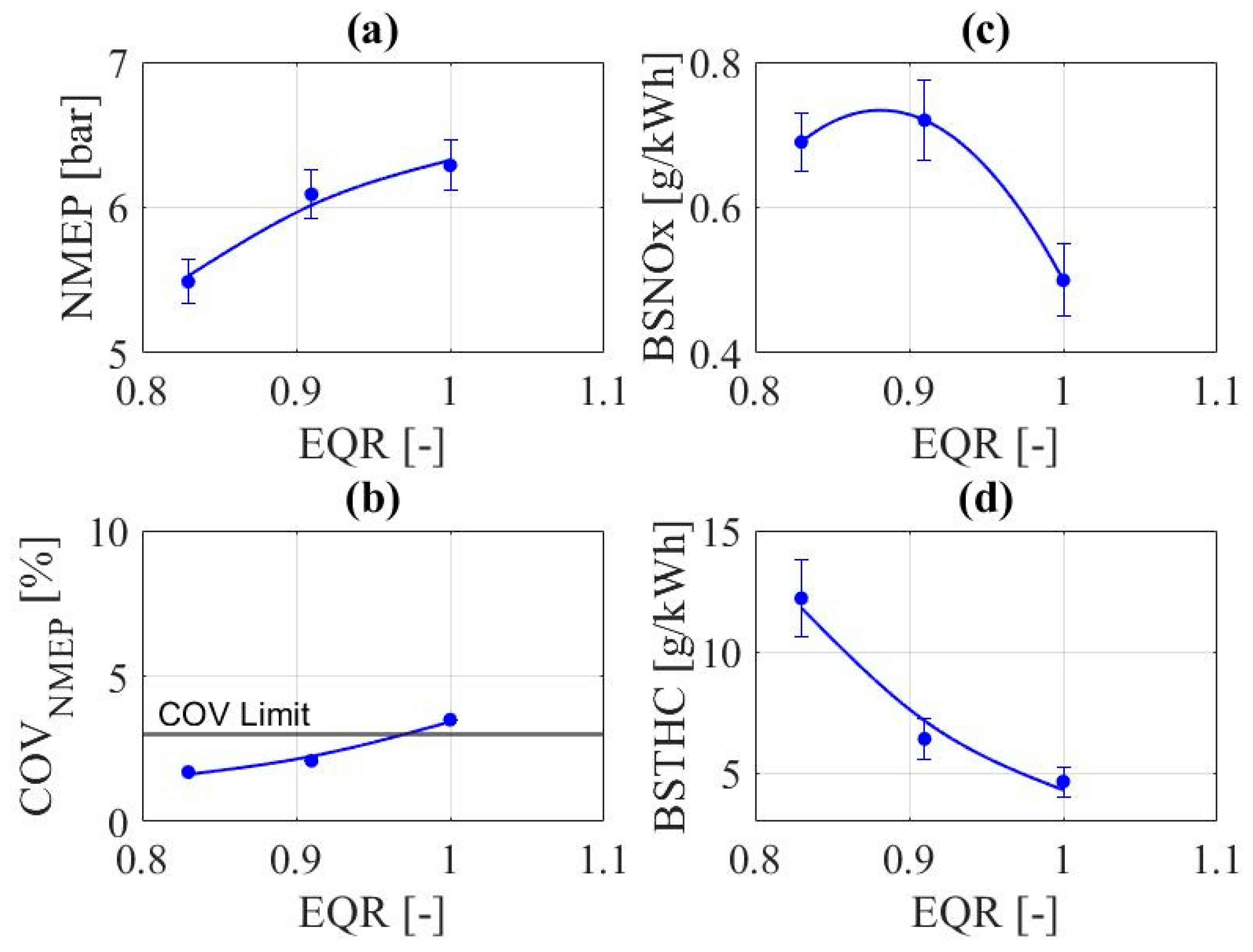
- Lean operations enabled lower loads by reducing the total fuel quantity in the intake premix for a given intake pressure. Lean operation increased NOx and unburned hydrocarbon emissions by 40% and 160%, respectively, while lean operation precludes using a TWC to control NOx emissions.
Author Contributions
Funding
Institutional Review Board Statement
Informed Consent Statement
Data Availability Statement
Acknowledgments
Conflicts of Interest
Nomenclature
| AFR | Air to Fuel Ratio | LHV | Lower Heating Value |
| BMEP | Brake Mean Effective Pressure | IMEP | Indicated Mean Effective Pressure |
| BSNOx | Brake Specific NOx | MAP | Manifold Air Pressure |
| BSTHC | Brake Specific THC | MBT | Maximum Brake Torque |
| CA50 | Crank Angle position at which 50% of the heat from combustion has been released | NG | Natural Gas |
| CO | Carbon Monoxide | NMEP | Net Mean Effective Pressure |
| COV | Coefficient of Variance | NOx | Oxides of Nitrogen |
| CR | Compression Ratio | P | Pressure |
| DSR | Diesel Substitution Ratio | SI | Spark-Ignition |
| EGR | Exhaust Gas Recirculation | SOC | Start of Combustion |
| EQR | Equivalence Ratio | SOI | Start of Injection |
| FS | Full Scale | T | Temperature |
| GHG | Green House Gases | THC | Total unburned Hydrocarbons |
| HP | High Pressure | TWC | Three-Way-Catalyst |
| ICE | Internal Combustion Engine | VGT | Variable Geometry Turbocharger |
| IMAT | Intake Manifold Air Temperature |
References
- Reitz, R.D.; Ogawa, H.; Payri, R.; Fansler, T.; Kokjohn, S.; Moriyoshi, Y.; Agarwal, A.; Arcoumanis, D.; Assanis, D.; Bae, C.; et al. IJER editorial: The future of the internal combustion engine. Int. J. Engine Res. 2020, 21, 3–10. [Google Scholar] [CrossRef] [Green Version]
- Karim, G.A. Dual-Fuel Diesel Engines; CRC Press: Boca Raton, FL, USA, 2015; Chapters: 3, 5, and 6. [Google Scholar] [CrossRef]
- Manns, H.J.; Brauer, M.; Dyja, H.; Beier, H.; Lasch, A. Diesel CNG—The Potential of a Dual Fuel Combustion Concept for Lower CO2 and Emissions; SAE2015-26-0048; SAE International: Warrendale, PA, USA, 2015. [Google Scholar]
- Karim, G.A. Combustion in Gas Fueled Compression: Ignition Engines of the Dual Fuel Type. J. Eng. Gas Turbines Power 2003, 125, 827–836. [Google Scholar] [CrossRef]
- Weaver, C.S.; Turner, S.H. Dual Fuel Natural Gas/Diesel Engines: Technology, Performance, and Emissions; SAE International: Warrendale, PA, USA, 1994. [Google Scholar] [CrossRef]
- Daisho, Y.; Yaeo, T.; Koseki, T.; Saito, T.; Kihara, R.; Quiros, E.N. Combustion and Exhaust Emissions in a Direct-Injection Diesel Engine Dual-Fueled with Natural Gas; SAE950465; SAE International: Warrendale, PA, USA, 1995. [Google Scholar] [CrossRef]
- Vávra, J.; Bortel, I.; Takáts, M.; Diviš, M. Emissions and performance of diesel–natural gas dual-fuel engine operated with stoichiometric mixture. Fuel 2017, 208, 722–733. [Google Scholar] [CrossRef]
- Zheng, J.; Wang, J.; Zhao, Z.; Wang, D.; Huang, Z. Effect of equivalence ratio on combustion and emissions of a dual-fuel natural gas engine ignited with diesel. Appl. Therm. Eng. 2019, 146, 738–751. [Google Scholar] [CrossRef]
- Yousefi, A.; Birouk, M.; Guo, H. An experimental and numerical study of the effect of diesel injection timing on natural gas/diesel dual-fuel combustion at low load. Fuel 2017, 203, 642–657. [Google Scholar] [CrossRef]
- Zhou, H.; Zhao, H.-W.; Huang, Y.-P.; Wei, J.-H.; Peng, Y.-H. Effects of Injection Timing on Combustion and Emission Performance of Dual-Fuel Diesel Engine under Low to Medium Load Conditions. Energies 2019, 12, 2349. [Google Scholar] [CrossRef] [Green Version]
- Valladolid, P.G.; Tunestal, P. Effects of Intake Manifold Conditions on Dual-Fuel CNG-Diesel Combustion in a Light Duty Diesel Engine Operated at Low Loads; SAE2016-01-0805; SAE International: Warrendale, PA, USA, 2016. [Google Scholar] [CrossRef]
- Guo, H.; Neill, W.S.; Liko, B. An Experimental Investigation on the Combustion and Emissions Performance of a Natural Gas–Diesel Dual Fuel Engine at Low and Medium Loads. In Proceedings of the ASME 2015 Internal Combustion Engine Division Fall Technical Conference, American Society of Mechanical Engineers, Houston, TX, USA, 8–11 November 2015. [Google Scholar] [CrossRef] [Green Version]
- Papagiannakis, R.G.; Hountalas, D.T. Combustion and exhaust emission characteristics of a dual fuel compression ignition engine operated with pilot diesel fuel and natural gas. Energy Convers. Manag. 2004, 45, 2971–2987. [Google Scholar] [CrossRef]
- Taniguchi, S.; Masubuchi, M.; Kitano, K.; Mogi, K. Feasibility Study of Exhaust Emissions in a Natural Gas Diesel Dual Fuel (DDF) Engine; SAE2012-01-1649; SAE International: Warrendale, PA, USA, 2012. [Google Scholar] [CrossRef]
- Liu, J.; Guo, Q.; Guo, J.; Wang, F. Optimization of a diesel/natural gas dual fuel engine under different diesel substitution ratios. Fuel 2021, 305, 121522. [Google Scholar] [CrossRef]
- Jamrozik, A.; Tutak, W.; Grab-Rogaliński, K. An Experimental Study on the Performance and Emission of the diesel/CNG Dual-Fuel Combustion Mode in a Stationary CI Engine. Energies 2019, 12, 3857. [Google Scholar] [CrossRef] [Green Version]
- Wang, Z.; Zhao, Z.; Wang, D.; Tan, M.; Han, Y.; Liu, Z.; Dou, H. Impact of pilot diesel ignition mode on combustion and emissions characteristics of a diesel/natural gas dual fuel heavy-duty engine. Fuel 2016, 167, 248–256. [Google Scholar] [CrossRef]
- Dronniou, N.; Kashdan, J.; Lecointe, B.; Sauve, K.; Soleri, D. Optical Investigation of Dual-fuel CNG/Diesel Combustion Strategies to Reduce CO2 Emissions. SAE Int. J. Engines 2014, 7, 873–887. [Google Scholar] [CrossRef]
- You, J.; Liu, Z.; Wang, Z.; Wang, D.; Xu, Y. Experimental analysis of inert gases in EGR on engine power and combustion characteristics in a stoichiometric dual fuel heavy-duty natural gas engine ignited with diesel. Appl. Therm. Eng. 2020, 180, 115860. [Google Scholar] [CrossRef]
- Papagiannakis, R.G.; Hountalas, D.T.; Rakopoulos, C.D.; Rakopoulos, D.C. Combustion and Performance Characteristics of a DI Diesel Engine Operating from Low to High Natural Gas Supplement Ratios at Various Operating Conditions; SAE2008-01-1392; SAE International: Warrendale, PA, USA, 2008. [Google Scholar] [CrossRef]
- Poorghasemi, K.; Saray, R.K.; Ansari, E.; Irdmousa, B.K.; Shahbakhti, M.; Naber, J.D. Effect of diesel injection strategies on natural gas/diesel RCCI combustion characteristics in a light duty diesel engine. Appl. Energy 2017, 199, 430–446. [Google Scholar] [CrossRef]
- Naber, J.D.; Henes, R.; Henes, E. High BMEP and High Efficiency Micro-Pilot Ignition Natural Gas Engine (Final Project Report); Office of Scientific and Technical Information (OSTI): Oak Ridge, TN, USA, 2020. [CrossRef]
- Taylor, B.N. Guidelines for evaluating and expressing the uncertainty of NIST measurement results. In Guidelines for Evaluating and Expressing the Uncertainty of NIST Measurement Results; National Institute of Standards and Technology: Gaithersburg, MD, USA, 1994. [Google Scholar] [CrossRef]
- Wärtsilä Methane Number Calculator. 2021. Available online: https://www.wartsila.com/marine/build/gas-solutions/methane-number-calculator (accessed on 6 September 2021).
- Bonfochi Vinhaes, V.; Yang, X.; Eggart, B.; McTaggart-Cowan, G.; Munshi, S.; Naber, J.; Shahbakhti, M. Multi-Variable Sensitivity Analysis and Ranking of Control Factors Impact in a Stoichiometric Micro-Pilot Natural Gas Engine at Medium Loads. In Proceedings of the 2022 SAE World Congress, Detroit, MI, USA, 5–7 April 2022. [Google Scholar]
- Ayala, F.A.; Gerty, M.D.; Heywood, J.B. Effects of Combustion Phasing, Relative Air-Fuel Ratio, Compression Ratio, and Load on SI Engine Efficiency; SAE2006-01-0229; SAE International: Warrendale, PA, USA, 2006; pp. 177–195. [Google Scholar] [CrossRef]
- Khosravi, M.; Rochussen, J.; Yeo, J.; Kirchen, P.; McTaggart-Cowan, G.; Wu, N. Effect of Fueling Control Parameters on Combustion Characteristics of Diesel-Ignited Natural Gas Dual-Fuel Combustion in an Optical Engine. In Proceedings of the ASME 2016 Internal Combustion Engine Division Fall Technical Conference, Greenville, SC, USA, 9–12 October 2016. [Google Scholar] [CrossRef]
- Alla, G.H.A.; Soliman, H.A.; Badr, O.A.; Rabbo, M.F.A. Effect of Pilot Fuel Quantity on the Performance of a Dual Fuel Engine; SAE1999-01-3597; SAE International: Warrendale, PA, USA, 1999. [Google Scholar] [CrossRef]
- Liu, J.; Yang, F.; Wang, H.; Ouyang, M.; Hao, S. Effects of pilot fuel quantity on the emissions characteristics of a CNG/diesel dual fuel engine with optimized pilot injection timing. Appl. Energy 2013, 110, 201–206. [Google Scholar] [CrossRef]
- Papagiannakis, R.; Hountalas, D.; Rakopoulos, C. Theoretical study of the effects of pilot fuel quantity and its injection timing on the performance and emissions of a dual fuel diesel engine. Energy Convers. Manag. 2007, 48, 2951–2961. [Google Scholar] [CrossRef]
- Zirngibl, S.; Wachtmeister, G. Extensive Investigation of a Common Rail Diesel Injector Regarding Injection Characteristics and the Resulting Influences on the Dual Fuel Pilot Injection Combustion Process; SAE2016-01-0780; SAE International: Warrendale, PA, USA, 2016. [Google Scholar] [CrossRef]
- Heywood, J.B. Internal Combustion Engine Fundamentals; McGraw-Hill Education: New York, NY, USA, 2018; Chapters: 4 and 11; ISBN 1260116107. [Google Scholar]
- Smith, I.; Chiu, J.; Bartley, G.; Jimenez, E.; Briggs, T.; Sharp, C. Achieving Fast Catalyst Light-Off from a Heavy-Duty Stoichiometric Natural Gas Engine Capable of 0.02 g/bhp-hr NOx Emissions; SAE2018-01-1136; SAE International: Warrendale, PA, USA, 2018. [Google Scholar] [CrossRef]


| No. of Cylinders | 6 |
| Bore and Stroke | 107 × 124 mm |
| Connecting Rod Length | 192 mm |
| Displacement Volume | 6.7 L |
| Compression Ratio | 15.0:1 |
| Aspiration | Turbocharged (VGT) + Charge Air Cooler + HP EGR + Throttle Valve |
| Diesel Micro-Pilot Injection System | HPCR injector 8 holes (168 microns diameter) |
| Diesel Injection Pressure | 600 to 2000 bar |
| Diesel Micro-Pilot Minimum Fuel Quantity | 3.3 mg/injection |
| Measurement | Accuracy | Full Scale | Uncertainty (Absolute) | Unit |
|---|---|---|---|---|
| In-Cylinder Pressure Transducer | ±0.30% FS | 0–250 | ±0.75 | bar |
| Engine Crank Angle Degree (Encoder) | ±1.00 | 360:1 | ±1.00 | Deg |
| Fuel Flow Rate (Diesel and NG) | ±0.05 FS | 0–30 | ±0.015 | g/s |
| Thermocouples | ±2.20 | 0–800 | ±2.20 | °C |
| Intake/Exhaust Manifold Pressure Transducer | ±0.08% FS | 0–6.89 | ±0.0055 | bar |
| Oil and Fuel Inlet Pressure | ±0.50% FS | 0–7/0–2 | ±0.035/0.010 | bar |
| Torque | ±0.05% FS | 0–5000 | ±2.50 | Nm |
| NOx Analyzer | ±1.00% FS | 0–5000 | ±50.0 | ppm |
| THC Analyzer | ±1.00% FS | 0–10,000 | ±100.0 | ppm |
| Measurement | Range | Uncertainty (Absolute) | Unit |
|---|---|---|---|
| NMEP | 4.70–8.00 | ±0.15 | Bar |
| Combustion Stability (COVNMEP) | 0.40–9.0 | ±0.05 | % |
| Ignition Delay | 1.70–5.0 | ± 0.08 | ms |
| Diesel Substitution Ratio | 86.0–93.2 | ±0.50 | % |
| CA50 | 12.0–32.0 | ±0.60 | °aTDC |
| Exhaust Gas Recirculation | 0.00–12.0 | ±0.20 | % |
| Equivalence Ratio | 0.80–1.0 | ±0.01 | - |
| BSNOx | 0.20–133 | ±34.1 | g/kWh |
| BSTHC | 2.10–37.0 | ±5.00 | g/kWh |
| Diesel (ULSD) | Density (kg/m3) at 15.6 °C, 1 atm | Lower Heating Value (MJ/kg) | Stoichiometric AFR | H/C | Cetane Number |
| 851.6 | 42.8 | 14.60 | 1.85 | 51.7 | |
| CNG | Density (kg/m3) at 20 °C, 1 atm | Lower Heating Value (MJ/kg) | Stoichiometric AFR | H/C | Methane Number * |
| 0.727 | 47.5 | 16.30 | 3.80 | 83.0 |
| Range of Operating Conditions Investigated | |||||||||
|---|---|---|---|---|---|---|---|---|---|
| Speed | EQR | MAP | Intake Temp. | CR | Diesel Pilot SOI | Diesel Inj. Pressure | EGR | Diesel Pilot Quantity | |
| RPM | - | kPa | °C | - | °bTDC | bar | % | mg/injection | |
| CA50 Study | 1200 | 1.0 | 80 (CR17.3); 85 (CR15.0) | 35 | 15.0; 17.3 | 2.0 to 15 | 1000 | 0 | 3.3 |
| Diesel Inj. Pressure Study | 15.0; 17.3 | 2.5 (CR17.3); 7.0 (CR15.0) | 600 to 1200 | 0 | 3.3 | ||||
| EGR Study | 15.0 | 7.0 to 15 | 600 | 0 to 12 | 3.3 | ||||
| Pilot quantity Study | 15.0 | 15 | 600 | 12 | 3.3 to 6.6 | ||||
| Reduced Compression Ratio (15.0) | Original Compression Ratio (17.3) | |
|---|---|---|
| Load (NMEP) [bar] | 6.20 | 5.20 |
| Indicated Fuel Conversion Efficiency [%] | 35.7 | 36.3 |
| Diesel Substitution Ratio [%] | 93.2 | 91.0 |
| Equivalence Ratio [-] | 1.00 | 1.00 |
| EGR [%] | 12.0 | 12.0 |
| Pilot Injection Pressure [bar] | 600 | 600 |
| Pilot Injection Quantity [mg/inj] | 3.30 | 3.30 |
| CA50 [°aTDC] | 26.0 | 24.0 |
| COV NMEP [%] | 3.50 | 3.30 |
| MAP [kPa] | 85.0 | 80.0 |
| Intake Manifold Temperature [°C] | 35.0 | 35.0 |
| EGT [°C] | 587 | 515 |
| Brake Specific NOx [g/kWh] | 0.50 | 0.25 |
| Brake Specific CO2 [g/kWh] | 590 | 538 |
| Brake Specific THC [g/kWh] | 4.20 | 8.90 |
Publisher’s Note: MDPI stays neutral with regard to jurisdictional claims in published maps and institutional affiliations. |
© 2022 by the authors. Licensee MDPI, Basel, Switzerland. This article is an open access article distributed under the terms and conditions of the Creative Commons Attribution (CC BY) license (https://creativecommons.org/licenses/by/4.0/).
Share and Cite
Bonfochi Vinhaes, V.; McTaggart-Cowan, G.; Munshi, S.; Shahbakhti, M.; Naber, J.D. Experimental Studies of Low-Load Limit in a Stoichiometric Micro-Pilot Diesel Natural Gas Engine. Energies 2022, 15, 728. https://doi.org/10.3390/en15030728
Bonfochi Vinhaes V, McTaggart-Cowan G, Munshi S, Shahbakhti M, Naber JD. Experimental Studies of Low-Load Limit in a Stoichiometric Micro-Pilot Diesel Natural Gas Engine. Energies. 2022; 15(3):728. https://doi.org/10.3390/en15030728
Chicago/Turabian StyleBonfochi Vinhaes, Vinicius, Gordon McTaggart-Cowan, Sandeep Munshi, Mahdi Shahbakhti, and Jeffrey D. Naber. 2022. "Experimental Studies of Low-Load Limit in a Stoichiometric Micro-Pilot Diesel Natural Gas Engine" Energies 15, no. 3: 728. https://doi.org/10.3390/en15030728
APA StyleBonfochi Vinhaes, V., McTaggart-Cowan, G., Munshi, S., Shahbakhti, M., & Naber, J. D. (2022). Experimental Studies of Low-Load Limit in a Stoichiometric Micro-Pilot Diesel Natural Gas Engine. Energies, 15(3), 728. https://doi.org/10.3390/en15030728