Article

Numerical Investigation on the Jet Characteristics and Combustion Process of an Active Prechamber Combustion System Fueled with Natural Gas

State Key Laboratory of Engines, Tianjin University, No. 92 Weijin Road, Nankai District, Tianjin 300072, China
*
Author to whom correspondence should be addressed.
Energies 2022, 15(15), 5356; https://doi.org/10.3390/en15155356
Submission received: 3 July 2022 / Revised: 21 July 2022 / Accepted: 22 July 2022 / Published: 24 July 2022

Abstract

:
An active prechamber turbulent ignition system is a forced ignition method for internal combustion engines fueled with low reactivity fuels, i.e., natural gas and gasoline, which could expand the lean-burn limit, promote flame propagation, and ensure cyclic stability. In the present study, the effects of charge concentration stratifications inside the prechamber on the jet characteristics and combustion process were numerically investigated using CONVERGE software coupled with a reduced methane mechanism by the coupling control of spark timing and prechamber global equivalence ratio. The results show that the jet characteristics and ignition mechanisms can be regulated by controlling the prechamber global equivalence ratio and spark timing. On the one hand, as the prechamber global equivalence ratio increases, the velocity of the jet increases firstly and then decreases, the temperature drops, and OH and CH2O radicals are reduced, but the stable combustion intermediates, CO and H2, are increased. Thus, the ignition mechanism changes from flame ignition (ignition by flame and reactive radicals) to jet ignition (ignition by hot combustion intermediates), and the ignition delay is shortened, but the combustion duration is extended, mainly due to more of the combustion intermediates, CO and H2, downstream of the jet. On the other hand, as spark timing is advanced, the jet velocity and the mass of the OH and CH2O radicals increase, which is conducive to flame ignition, and the ignition delay and combustion duration are reduced.

1. Introduction

Due to climate change and environmental issues, it is increasingly important to reduce the greenhouse gas emissions from the transportation section, which has been regarded as one of the most important sources of greenhouse gases. Natural gas is a conventional low carbon fuel, which almost eliminates the emissions of sulfur oxides and particulate matter. When releasing per unit energy, it produces at least 30% less carbon dioxide than conventional petroleum fuels [1]. However, the limited flame propagation speed of natural gas is one of the major issues for natural gas engine thermal efficiency improvement. In addition, ignition and combustion stability become another issue when lean combustion is used for efficiency improvement, leading to problems such as an increase in unburned hydrocarbons and cycle-to-cycle variability.
Many studies show that the turbulent jet ignition (TJI) system can be a valid solution to solve the above-mentioned problems in natural gas engines [2,3].
TJI usually features a small prechamber (1–2%) with several nozzles, the reactive gases or turbulent flames produced by the prechamber are injected from the nozzle into the main chamber to ignite the lean mixture [4,5]. A large number of reactive species and high intensity turbulence make the ignition energy a million times higher than a conventional spark plug [6]. The prechamber can be mainly divided into two types: the passive prechamber and active prechamber. For the former, the fuel in the prechamber comes from the main chamber, while the latter has an individual fuel supply system. Blaxill et al. [7,8,9] conducted extensive research on both active and passive prechambers to analyze the effects of TJI on the combustion performance of engines. Benajes et al. [10] compared the potential of a passive prechamber and active prechamber in a high compression ratio engine. The results indicate that both passive prechambers and active prechambers could improve the combustion stability and efficiency, but active prechamber systems show further potential on expanding the lean-burn limit. Jamrozik et al. [11,12,13] carried out experiments and simulation studies on active prechambers. They found the active prechamber combustion system ensures burning ultra-lean mixtures with λ up to 2.0, and the COV of IMEP was approximately 3%.
Many researchers have studied the effect of various factors on TJI process. Shah et al. [14] experimentally explored the effect of prechamber volume on the ignition characteristics, and the results showed that the prechamber with a larger volume could provide higher ignition energy. Bigalli et al. [15] numerically studied the effects of prechamber shape and nozzle diameter on the combustion characteristics and found the orifice size has the most significant effect. Gentz et al. [16] studied the effects of nozzle diameter and number on TJI ignition by performing combustion visualization. It was found that in a stoichiometric mixture, jets produced by a nozzle with a wider spatial distribution could promote the rapid development of combustion, and in a lean mixture, a small nozzle diameter with a high jet velocity is required to ignite. Thelen et al. [17] numerically investigated the effect of spark plug position inside the prechamber and observed that the spark plug being away from the nozzle provides better ignition performance. Wang et al. [18] conducted a numerical simulation analysis on the effect of initial temperature on jet characteristics. Their results showed that the initial ignition position moved significantly towards the exit of the nozzle with the increase in temperature. Ju et al. [19] analyzed the effect of excess air ratio and premixed pressure through experiments, and found that ambient pressure has a greater effect on the flame propagation than excess air ratio air as the initial pressure increases. Onofrio et al. [20] studied the effect of spark timing on engine performance and found that a delay of spark timing increases the combustion duration and deteriorates engine performance. Zheng et al. [21] investigated the effect of injection parameters on the development of turbulent jet flame in rapid compression machines. Their results showed the initial lambda of the prechamber has a great influence on the jet velocity, while the initial lambda of the main chamber affects the jet penetration distance.
Based on the above studies, it could be found that the structures and control parameters of the prechamber have significant effects on the jet characteristics and combustion process. However, the TJI process is complicated due to turbulence, heat, and chemistry [22]. In order to understand the physical and chemical mechanisms behind it, many researchers have investigated the internal control and influential mechanisms of the TJI process. Benekos et al. [23,24] conducted a two-dimensional numerical simulation study on the ignition and initial stage of jet ignition, and found that the turbulent jet creates an intense flow field with vortical structures, which promote the interaction between jet and unburned mixture. Allison et al. [25] found that local quenching of free radicals occurs when passing through the orifice, which would change the compositional structure of the jet. Toulson et al. [26] investigated the mechanism of jet ignition through experiments and numerical simulations. The results showed that the type and quantity of free radicals play a major role in the chemical characteristics of jet ignition, while heat and turbulence play a secondary role. Qin et al. [27] used direct numerical simulation to investigate the transient mixing and ignition mechanisms of the prechamber. It was found that OH, CH2O, and HO2 have important effects on ignition and flame propagation in the main chamber. Pan et al. [28] numerically investigated the combustion evolutions of turbulent jet ignition. It was found that the flame configuration in the main chamber changes from normal turbulent jet flame propagation to spherical flame propagation as the temperature increases. Biswas et al. [29] defined two ignition mechanisms by using simultaneous high-speed schlieren and OH radical chemiluminescence imaging, jet ignition, and flame ignition, with the major difference between these modes being whether the flame is quenched.
As mentioned above, the jet characteristics and ignition mechanisms are complex and affected by many factors. However, the above-mentioned studies were mainly focused on passive prechambers, and fundamental studies on the turbulent jet formation and ignition process of active prechambers are still urgently needed—for instance, the effects of concentration stratifications inside the prechamber on internal flame and jet development. Motivated by this, this work numerically investigated the effects of prechamber concentration stratifications on the jet characteristics and combustion process, which is controlled by the spark timing and prechamber equivalence ratio in a constant volume chamber with an active prechamber fueled with natural gas.

2. Numerical Method

2.1. Numerical Model

This work was conducted using the computational fluid dynamics (CFD) software, CONVERGE [30]. Table 1 shows the major sub-models in the simulation. Large Eddy Simulation (LES) is adopted to simulate the turbulence. In addition, a G-equation coupled with a chemical reaction mechanism is applied for the combustion process prediction. Methane is used as a single component surrogate of natural gas, and the methane mechanism used in the present simulation includes 40 species and 139 reactions, which has been extensively validated with experimental data from shock tubes [31]. The spark event was modeled as a 0.5 mm spherical energy source centered in the plug gap, initiating at the spark time.
Figure 1 shows the three-dimensional geometric structure of the computational domain, which contains a prechamber, main chamber, nozzle, spark plug, and natural gas injector. The prechamber has dimensions of L (length) × D (diameter) = 40 mm × 20 mm. The main chamber has dimensions of L (length) × D (diameter) = 120 mm × 100 mm. The prechamber-to-main chamber volume ratio is 0.0132. The nozzle diameter is 2 mm, and the height is 17 mm. The spark plug and natural gas injector are located at the top of the prechamber—the former is centered, and the latter is biased.
Based on the above geometric model, in order to ensure the accuracy and efficiency of the numerical simulation, the basic mesh size of the prechamber and nozzle was set as 0.5 mm, and the basic mesh size of the main chamber was set as 4 mm. During the calculation, the mesh was generated by using four level automatic mesh refinement. In the end, the minimum mesh of the whole model was 0.25 mm and the maximum number of meshes was 2 × 10⁶.
The initial temperature in both the prechamber and main chamber was 700 K, and the pressure was 4 MPa, which is similar to the representative conditions of an actual engine. In order to individually explore the turbulent jet characteristics and also the ignition process in the main chamber, either N2 or lean CH4/air mixture was adopted in the main chamber.

2.2. Modeling Validation

The experimental results from Biswas et al. [29] were used to validate the current model. The conditions of the validation cases are given in Table 2.
Figure 2 shows the comparison between the experimental results and simulation results. The area shown is part of the main chamber, where x = 0 and z = 0 is the center of the nozzle exit. The left figures are the OH chemiluminescence images in the experiments, and the right figures are the OH mass fraction distribution images in the simulations. The upper figures are the comparison results of case 1, and the bottom figures are the results of case 2. In case 1, OH radicals could not be detected at the nozzle exit as the jet appears. After some time, a large number of OH radicals could be observed at a few centimeters downstream of the nozzle. Whereas, in case 2, a large number of OH radicals were detected as soon as the jet entered the main chamber, which means the flame is not quenched. Obviously, the ignition mechanisms of the two cases are different: case 1 is jet ignition and case 2 is flame ignition. The former is driven by the hot combustion products generated by the prechamber, and the latter is characterized by a jet of wrinkled turbulent flames and reactive free radicals. In both cases, the simulation results are generally in good agreement with the experimental results, so it can be considered that the model can predict the shape of the jet and ignition position well.

2.3. Definition of Jet Characteristics

Jet characteristics play a key role in ignition mechanisms and flame propagation. Table 3 shows the definition of the jet characteristics in this work. The high-speed jet disturbs the gas in the main combustion chamber so that the jet is in full contact with the unburned mixture, which is called the mixing characteristic. In addition, the jet carries heat and combustion products into the main combustion chamber, and this is called the thermal characteristic and chemical characteristic. In this work, the velocity of the jet center at the nozzle exit and penetration distance were used to represent the mixing characteristics of the jet. Among the mixing characteristics, there is no unified definition of jet penetration distance at present. Therefore, this work used the method of specifying the critical temperature to define the penetration distance. According to the literature [35], a temperature isosurface of 1200 K distinguished the burned zone between the unburned zone, so this paper defined the maximum length of the jet temperature that is higher than 1200 K as the jet penetration distance. Regarding the thermal characteristic, the jet temperature was used to represent it. The combustion products in the jet include highly-reactive free radicals, combustion intermediates, and complete combustion products. According to the literature [27], the heat release rate is proportional to the product of the reactive radicals, OH and CH2O, mass fraction, and the stable combustion intermediates, CO and H2, in the jet contribute greatly to the heat release. Therefore, this paper analyzed these four key species to explore the chemical characteristics of the turbulent jet on combustion.

3. Results and Discussion

3.1. Effect of Spark Timing on Jet Characteristics

The concentration stratifications in the active prechamber are different at different spark timings, which affects the flame propagation in the prechamber and jet characteristics. The conditions for studying the effect of spark timing on jet characteristics are specified in Table 4, wherein N2 is specified in the main chamber.
Figure 3 shows the distribution of the equivalence ratio in the prechamber for different spark timings. With the delay of spark timing, fuel stratification is reduced and the mixture distribution becomes more homogeneous in the prechamber. As can be seen, when spark timing is 3 ms, a fuel-rich region exists near the spark plug, and as the spark timings retard, the spark plug is surrounded by an almost stoichiometric mixture. In addition, it is observed that fuel-rich regions are mainly located in the top and middle of the prechamber, wherein feasible ignition conditions are available around the spark plug.
Figure 4 depicts the pressure traces of the prechamber for different spark timings. The maximum pressure of the prechamber decreases with the delay in spark timing. However, when the spark timing is delayed later than 5 ms, the effects of the spark timing on concentration stratification in the prechamber, and consequently on the pressure traces of the prechamber, become weaker. The velocity of the jet center at the nozzle exit for different spark timings is shown in Figure 5. Before spark timing, methane injection causes a disturbance in the prechamber, and part of the mixture flows to the main chamber. After spark timing, the pressure of the prechamber rises and part of the unburned mixture is pushed into the main chamber, which is called the cold jet. As the burning progresses in the precombustion chamber, the hot jet containing the majority of the combustion products appears in the main combustion chamber. The jet velocity at the nozzle exit is related to the pressure of the prechamber. The greater the pressure difference between the prechamber and main chamber, the higher the jet velocity. Therefore, jet velocity increases with the advance of spark timing; however, when the spark timings are 5 ms and 7 ms, the maximum jet velocity differences are small.
Figure 6 shows the jet temperature distribution and the centerline temperature traces for different spark timings at 3 ms after the hot jet appeared. It can be seen that the spark timing has little influence on the temperature characteristics and the penetration distance of the jet. Within 40 mm below the nozzle exit, the jet temperature is almost stable and remains above 2000 K. Then, the jet temperature drops rapidly between z = 40 mm and z = 50 mm. At the downstream locations, z > 50 mm, the jet temperature oscillates continuously. In all cases, the penetration distance is around 60 mm.
Figure 7 shows the distribution of the major species in the jet for different spark timings at 3 ms after the hot jet appeared. The highly-reactive OH radicals carried by the jet exist close to the nozzle exit where the temperature is high. Certain CH2O molecules can be observed at the edge of the jet with relatively lower temperatures, and high concentrations of CH2O can be found at the bottom of the main chamber. In addition, the combustion intermediates, CO and H2, are mainly located near the nozzle exit region. The major species mass traces of the jet for different spark timings are shown in Figure 8. As the hot jet enters the main chamber, OH, CH2O, CO, and H2 gradually increase in the main chamber, then these species gradually decrease due to chemical reactions taking place inside the jet plume. As analyzed above, the chemical characteristics of the jets vary greatly under different spark timings, and significantly higher concentrations of OH, CH2O, CO, and H2 can be observed in the jet with the advance of spark timing.

3.2. Effect of the Prechamber Global Equivalence Ratio on Jet Characteristics

In this section, the effects of the prechamber global equivalence ratio on jet characteristics are explored by varying the methane injection mass of the prechamber. The boundary conditions of the simulations are given in Table 5, and there is no fuel in the main chamber.
From the above section, it is found that an earlier spark timing shows advantages with jet velocity and chemical characteristics for ignition and combustion control. Figure 9 shows the distribution of the equivalence ratio in the prechamber for different global equivalence ratio cases. It can be seen that a high fuel concentration region exists in the upper right of the prechamber at 3 ms when ϕpc =1.25, wherein the equivalence ratio near the spark plug is suitable for spark ignition. However, the mixture near the spark plugs is too rich to ignite at 3 ms and 5 ms when ϕpc =1.5. At 7 ms, the mixture is leaner near the spark plug and the equivalence ratio is less than 1.5, which favors spark ignition. Therefore, the spark timings for three different prechamber global equivalence ratios, i.e., 1.0, 1.25, and 1.5, are 3 ms, 5 ms and 7 ms, respectively.
Figure 10 depicts the pressure traces of the prechamber for different prechamber global equivalence ratio cases. As the prechamber global equivalence ratio increases from 1.0 to 1.5, the maximum pressure of the prechamber increases first and then decreases. As shown in Figure 9, most of the mixture in the prechamber is near the stoichiometric ratio when ϕpc = 1.25. As a result, the combustion rate is the fastest and results in the highest peak pressure. The velocity of the jet center at the nozzle exit for different prechamber global equivalence ratios are shown in Figure 11. The greater the pressure of the prechamber, the higher the jet velocity at the nozzle exit. Therefore, when the prechamber global equivalence ratio increases, the maximum jet velocity firstly increases and then decreases. In all cases, the maximum jet velocity at the nozzle exit exceeds 900 m/s.
Figure 12 shows the distribution of the jet temperature and centerline temperature traces for different prechamber global equivalence ratios at 3 ms after the hot jet appeared. When the prechamber global equivalence ratio increases, the jet temperature at the exit of nozzle decreases. When ϕpc = 1, the jet temperature at the exit of nozzle is about 2150 K, while this temperature drops to about 2000 K when ϕpc = 1.5. In addition, although the prechamber global equivalence ratio has a significant influence on jet temperature, the jet penetration distances are quite similar—around 60 mm in all cases.
Figure 13 shows the distribution of major species in the jet for different prechamber global equivalence ratios at 3 ms after the hot jet appeared. When the prechamber global equivalence ratio increases, the OH and CH2O mass fraction in the jet decreases, while both the CO and H2 mass fraction increases. When ϕpc = 1.25 and ϕpc = 1.5, there is very little or no OH and CH2O radicals in the jet, but a large number of the combustion intermediates, CO and H2, diffuses from the exit of the nozzle to the bottom of the main chamber.

3.3. Effect of the Jet Characteristics on Ignition and Combustion in the Main Chamber

In this section, the effects of various turbulent jet characteristics on ignition and combustion were studied by adding a CH4/air mixture with an equivalence ratio of 0.5 into the main chamber.
The distribution of major species in the main chamber at 3 ms after the hot jet entered the main chamber is shown in Figure 14. For different spark timings, the ignition mechanisms were not significantly affected by the velocity and chemical characteristics. The jets all carry a large number of OH radicals. This indicates that the flame passes through the nozzle without extinction, and the flame and reactive radicals ignite the mixture in the main chamber, which belongs to flame ignition. Due to the lean mixture in the main chamber, flame ignition does not give full play to its advantage of quickly igniting the surrounding mixture. For different prechamber global equivalence ratios, the differences in the velocity, temperature, and chemical characteristics have an important influence on the ignition mechanisms, among which the chemical characteristics play a key role. Comparing Figure 13 with Figure 14, the jet carries little or no OH and CH2O radicals when ϕpc = 1.25 and ϕpc = 1.5. At the initial stage of ignition, the stable combustion intermediates, CO and H2, in the main chamber decrease, while the OH and CH2O radicals in the downstream of the jets increase greatly. This indicates that the hot combustion intermediates, CO and H2, are oxidized in the downstream of the jets, thus igniting the surrounding mixture, which belongs to jet ignition. Therefore, as the prechamber global equivalence ratio increased, the OH and CH2O reactive radicals in the jet decrease, and while the combustion intermediates, CO and H2, increase, the ignition mechanisms change from flame ignition to jet ignition.
Figure 15 shows the histograms of the ignition delay and combustion duration for different spark timings and prechamber global equivalence ratios. The ignition delay represents the time duration from the spark ignition to when the heat release reaches 10% of the cumulated heat release in the main chamber, and the combustion duration represents the time duration from when the heat release reaches 10% of the cumulated heat release in the main chamber to 90%. It is seen that with the advance of spark timing, the ignition delay and combustion duration are shortened. On the one hand, with the advance of spark timing, the jet velocity is higher, and the jet disturbs the main chamber more intensely, which is conducive to the transfer of heat and the mixing of chemical components. On the other hand, with the advance of spark timing, there are more reactive free radicals and important combustion intermediates in the jet, which promote the chemical reaction and improve the ignition ability. With the increase of the prechamber global equivalence ratio, the ignition delay is shortened, but the combustion duration increases. It is mainly because the hot combustion intermediates, CO and H2, that are downstream of the jet increase and ignite the lean mixture faster, but the ignition initiation location moves towards the bottom of the main chamber.

4. Conclusions

In this paper, a numerical investigation was conducted to explore the effects of prechamber concentration stratifications on the jet characteristics and combustion process in a turbulent jet ignition combustion engine based on a constant volume chamber, which is controlled by the spark timing and fuel mass (CH4) inside the prechamber. The main conclusions of this present study are summarized as follows:
(1)
The sparking timing has a great impact on the jet velocity and chemical characteristics, while it has little impact on the thermal characteristics and penetration distance. With the earlier spark timing, the jet velocity is higher, and the jet contains more reactive chemical components, such as OH and CH2O radicals.
(2)
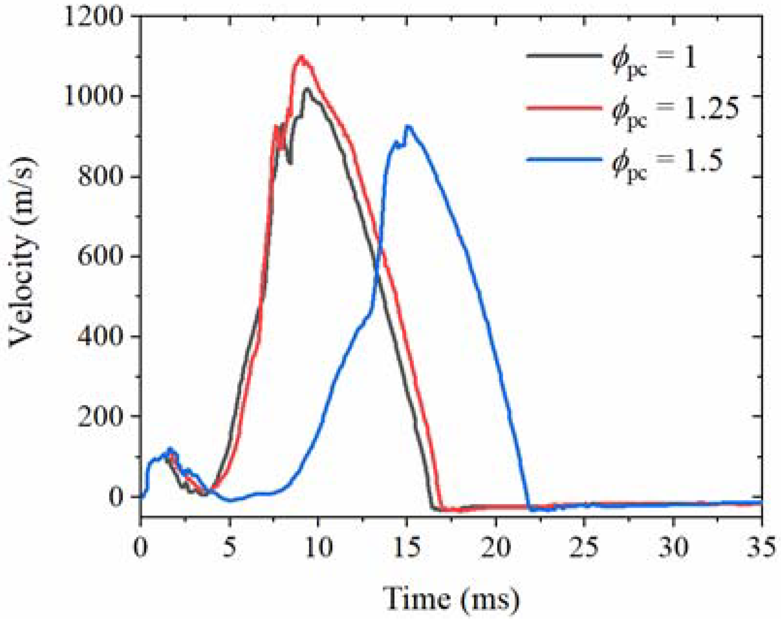
The prechamber global equivalence ratio has a great impact on the jet velocity, temperature, and chemical characteristics, while it has almost no impact on the penetration distance. With the increase of the prechamber global equivalence ratio, the velocity of the jet increases firstly and then decreases, the temperature drops, and the OH and CH2O free radicals are reduced, but the combustion intermediates, CO and H2, increase.
(3)
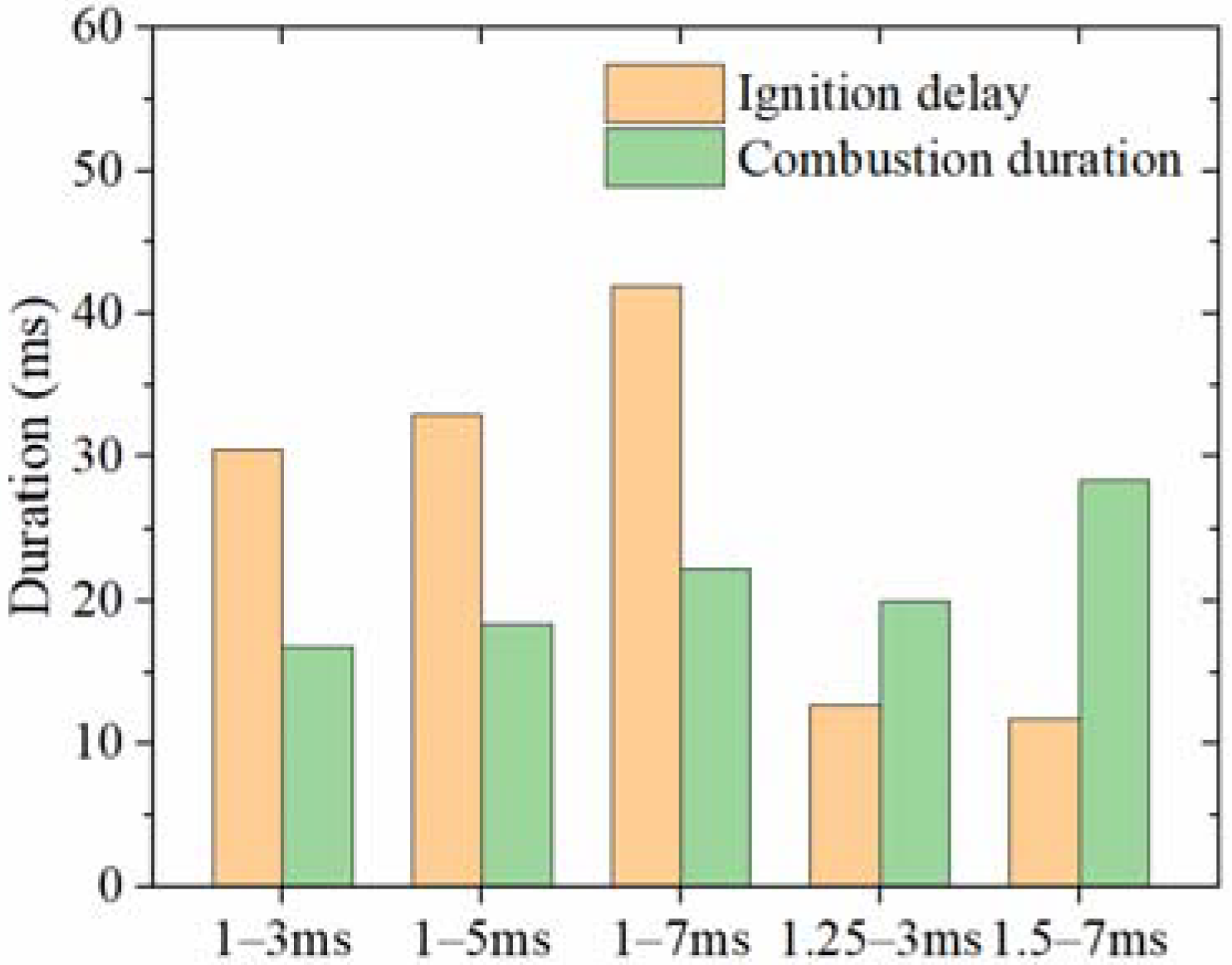
Two different ignition mechanisms can be identified in the main chamber, i.e., flame ignition (ignition by flame and reactive free radicals) and jet ignition (ignition by hot combustion intermediates). As the prechamber global equivalence ratio increases, the ignition mechanism changes from flame ignition to jet ignition, and the ignition delay is shortened, but the combustion duration is extended, mainly due to an increase in hot combustion intermediates, CO and H2, downstream of the jet.
(4)
The differences in the jet characteristics caused by spark timings have a limited effect on the ignition mechanism in the main chamber. Furthermore, the ignition mechanisms for different spark timings are all flame ignition. However, a higher jet velocity and more reactive intermediate species are beneficial to reduce the ignition delay and combustion duration with an earlier spark timing.

Author Contributions

Conceptualization, H.W.; methodology, L.X.; validation, G.L.; investigation, G.L.; writing—original draft preparation, L.X.; writing—review and editing, Z.Z. and H.W.; supervision, M.Y.; funding acquisition, M.Y. and H.W. All authors have read and agreed to the published version of the manuscript.

Funding

This research was funded by the National Natural Science Foundation of China (NSFC), grant number 51876140 and 51921004.

Institutional Review Board Statement

Not applicable.

Informed Consent Statement

Not applicable.

Conflicts of Interest

The authors declare no conflict of interest.

References

  1. Reynolds, C.; Evans, R.; Andreassi, L.; Cordiner, S.; Mulone, V. The Effect of Varying the Injected Charge Stoichiometry in a Partially Stratified Charge Natural Gas Engine. In SAE Technical Paper; 2005-01-0247; SAE International: Warrendale, PA, USA, 2005. [Google Scholar]
  2. Sasaki, H.; Sekiyama, S.; Nakashima, K. A new combustion system of a heat-insulated natural gas engine with a prechamber having a throat valve. Int. J. Engine Res. 2002, 3, 197–208. [Google Scholar] [CrossRef]
  3. Alvarez, C.E.C.; Couto, G.E.; Roso, V.R.; Thiriet, A.B.; Valle, R.M. A review of prechamber ignition systems as lean combustion technology for si engines. Appl. Therm. Eng. 2018, 128, 107–120. [Google Scholar] [CrossRef]
  4. Attard, W.P.; Fraser, N.; Parsons, P.; Toulson, E. A Turbulent Jet Ignition Pre-Chamber Combustion System for Large Fuel Economy Improvements in a Modern Vehicle Powertrain. SAE Int. J. Engines 2010, 3, 20–37. [Google Scholar] [CrossRef] [Green Version]
  5. Bunce, M.; Blaxill, H.; Kulatilaka, W.; Jiang, N. The Effects of Turbulent Jet Characteristics on Engine Performance Using a Pre-Chamber Combustor. In SAE Technical Paper; 2014-01-1195; SAE International: Warrendale, PA, USA, 2014. [Google Scholar]
  6. Olsen, D.B.; Lisowski, J.M. Prechamber NOx formation in low BMEP 2-stroke cycle natural gas engines. Appl. Therm. Eng. 2009, 29, 687–694. [Google Scholar] [CrossRef]
  7. Attard, W.P.; Blaxill, H.; Anderson, E.K.; Litke, P. Knock Limit Extension with a Gasoline Fueled Pre-Chamber Jet Igniter in a Modern Vehicle Powertrain. SAE Int. J. Engines 2012, 5, 1201–1215. [Google Scholar] [CrossRef]
  8. Bunce, M.; Blaxill, H. Sub-200 g/kWh BSFC on a Light Duty Gasoline Engine. In SAE Technical Paper; 2016-01-0709; SAE International: Warrendale, PA, USA, 2016. [Google Scholar]
  9. Peters, N.; Subramanyam SK, P.; Bunce, M.; Blaxill, H.; Cooper, A. Optimization of Lambda across the Engine Map for the Purpose of Maximizing Thermal Efficiency of a Jet Ignition Engine. SAE Int. J. Engines 2020, 2, 3140–3150. [Google Scholar]
  10. Benajes, J.; Novella, R.; Gomez-Soriano, J.; Martinez-Hernandiz, P.J.; Libert, C.; Dabiri, M. Evaluation of the passive pre-chamber ignition concept for future high compression ratio turbocharged spark-ignition engines. Appl. Energy 2019, 248, 576–588. [Google Scholar] [CrossRef]
  11. Jamrozik, A.; Tutak, W. Theoretical analysis of air-fuel mixture formation in the combustion chambers of the gas engine with two-stage combustion system. Bull. Pol. Acad. Sci. Tech. Sci. 2014, 62, 779–790. [Google Scholar] [CrossRef] [Green Version]
  12. Jamrozik, A.; Tutak, W.; Kociszewski, A.; Sosnowski, M. Numerical simulation of two-stage combustion in SI engine with prechamber. Appl. Math. Model. 2013, 37, 2961–2982. [Google Scholar] [CrossRef]
  13. Szwaja, S.; Jamrozik, A.; Tutak, W. A two-stage combustion system for burning lean gasoline mixtures in a stationary spark ignited engine. Appl. Energy 2013, 105, 271–281. [Google Scholar] [CrossRef]
  14. Shah, A.; Tunestal, P.; Johansson, B. Effect of Pre-Chamber Volume and Nozzle Diameter on Pre-Chamber Ignition in Heavy Duty Natural Gas Engines. In SAE Technical Paper; 2015-01-0867; SAE International: Warrendale, PA, USA, 2015. [Google Scholar]
  15. Bigalli, S.; Catalani, I.; Balduzzi, F.; Matteazzi, N.; Agostinelli, L.; De Luca, M.; Ferrara, G. Numerical Investigation on the Perfor-mance of a 4-Stroke Engine with Different Passive Pre-Chamber Geometries Using a Detailed Chemistry Solver. Energies 2022, 15, 4968. [Google Scholar] [CrossRef]
  16. Gentz, G.; Thelen, B.; Gholamisheeri, M.; Litke, P.; Brown, A.; Hoke, J.; Toulson, E. A study of the influence of orifice diameter on a turbulent jet ignition system through combustion visualization and performance characterization in a rapid compression machine. Appl. Therm. Eng. 2015, 81, 399–411. [Google Scholar] [CrossRef]
  17. Thelen, B.; Toulson, E. A Computational Study of the Effects of Spark Location on the Performance of a Turbulent Jet Ignition System. In SAE Technical Paper; SAE International: Warrendale, PA, USA, 2016-01-0608; 2016. [Google Scholar]
  18. Wang, N.; Liu, J.; Chang, W.; Lee, C.-F. The Effect of In-Cylinder Temperature on the Ignition Initiation Location of a Pre-Chamber Generated Hot Turbulent Jet. In SAE Technical Paper; 2018-01-0184; SAE International: Warrendale, PA, USA, 2018. [Google Scholar]
  19. Ju, D.; Huang, Z.; Li, X.; Zhang, T.; Gai, W. Comparison of open chamber and pre-chamber ignition of methane/air mixtures in a large bore constant volume chamber: Effect of excess air ratio and pre-mixed pressure. Appl. Energy 2020, 260, 114319. [Google Scholar] [CrossRef]
  20. Onofrio, G.; Napolitano, P.; Abagnale, C.; Guido, C.; Beatrice, C. Model Development of a CNG Active Pre-chamber Fuel Injection System. In SAE Technical Paper; 2021-24-0090; SAE International: Warrendale, PA, USA, 2021. [Google Scholar]
  21. Zheng, Z.Y.; Wang, L.; Pan, J.Y.; Pan, M.Z.; Wei, H.Q. Numerical investigations on turbulent jet ignition with gasoline as an auxiliary fuel in rapid compression machines. Combust. Sci. Technol. 2021, 1–20. [Google Scholar] [CrossRef]
  22. Bunce, M.; Blaxill, H. Methodology for Combustion Analysis of a Spark Ignition Engine Incorporating a Pre-Chamber Combustor. In SAE Technical Paper; 2014-01-2603; SAE International: Warrendale, PA, USA, 2014. [Google Scholar]
  23. Benekos, S.; Frouzakis, C.E.; Giannakopoulos, G.K.; Bolla, M.; Wright, Y.M.; Boulouchos, K. Prechamber ignition: An exploratory 2-D DNS study of the effects of initial temperature and main chamber composition. Combust. Flame 2020, 215, 10–27. [Google Scholar] [CrossRef]
  24. Benekos, S.; Frouzakis, C.E.; Giannakopoulos, G.K.; Altantzis, C.; Boulouchos, K. A 2-D DNS study of the effects of nozzle geometry, ignition kernel placement and initial turbulence on prechamber ignition. Combust. Flame 2021, 225, 272–290. [Google Scholar] [CrossRef]
  25. Allison, P.M.; de Oliveira, M.; Giusti, A.; Mastorakos, E. Pre-chamber ignition mechanism: Experiments and simulations on turbulent jet flame structure. Fuel 2018, 230, 274–281. [Google Scholar] [CrossRef] [Green Version]
  26. Toulson, E.; Watson, H.C.; Attard, W.P. Modeling of Alterative Prechamber Fuels in Jet Assisted Ignition of Gasoline and LPG. In SAE Technical Paper; 2009-01-0721; SAE International: Warrendale, PA, USA, 2009. [Google Scholar]
  27. Qin, F.; Shah, A.; Huang, Z.; Peng, L.; Tunestal, P. Detailed numerical simulation of transient mixing and combustion of premixed methane/air mixtures in a pre-chamber/main-chamber system relevant to internal combustion engines. Combust. Flame 2018, 188, 357–366. [Google Scholar] [CrossRef]
  28. Pan, J.; He, Y.; Li, T.; Wei, H.; Wang, L.; Shu, G. Effect of Temperature Conditions on Flame Evolutions of Turbulent Jet Ignition. Energies 2021, 14, 2226. [Google Scholar] [CrossRef]
  29. Biswas, S.; Tanvir, S.; Wang, H.; Qiao, L. On ignition mechanisms of premixed CH4/air and H2/air using a hot turbulent jet generated by pre-chamber combustion. Appl. Therm. Eng. 2016, 106, 925–937. [Google Scholar] [CrossRef]
  30. Richards, K.J.; Senecal, P.K.; Pomraning, E. CONVERGE Manual (Version 2.3); Convergent Science Inc.: Madison, WI, USA, 2016. [Google Scholar]
  31. Huang, J.; Hill, P.G.; Bushe, W.K.; Munshi, S.R. Shock-tube study of methane ignition under engine-relevant conditions: Experiments and modeling. Combust. Flame 2004, 136, 25–42. [Google Scholar] [CrossRef]
  32. Muller, M.; Freeman, C.; Zhao, P.; Ge, H. Numerical Simulation of Ignition Mechanism in the Main Chamber of Turbulent Jet Ignition System. In Proceedings of the ASME 2018 Internal Combustion Engine Division Fall Technical Conference, San Diego, CA, USA, 4–7 November 2018. [Google Scholar]
  33. Ewald, J.; Peters, N. A level set based flamelet model for the prediction of combustion in spark ignition engines. In Proceedings of the 15th International Multidimensional Engine Modeling User’s Group Meeting, Detroit, MI, USA, 20 April 2005. [Google Scholar]
  34. O’Rourke, P.J.; Amsden, A.A. The TAB Method for Numerical Calculation of Spray Droplet Breakup; Los Alamos National Lab: Los Alamos, NM, USA, 1987. [Google Scholar]
  35. Liu, L.; Wu, Y.; Xiong, Q.; Liu, T. Analysis on flow motion and combustion process in pre-chamber and main chamber for low-speed two-stroke dual-fuel engine. In SAE Technical Paper; 2019-01-2175; SAE International: Warrendale, PA, USA, 2019. [Google Scholar]
Figure 1. Three-dimensional geometric structure.
Energies 15 05356 g001
Figure 2. Comparison between the experimental results (left) and the simulation results (right).
Energies 15 05356 g002
Figure 3. Distribution of equivalence ratio in the prechamber for different spark timings.
Energies 15 05356 g003
Figure 4. Pressure traces of prechamber for different spark timings.
Energies 15 05356 g004
Figure 5. Velocity of jet center at nozzle exit for different spark timings.
Energies 15 05356 g005
Figure 6. Distribution of jet temperature and centerline temperature traces for different spark timings at 3 ms after the hot jet appeared.
Energies 15 05356 g006
Figure 7. Distribution of major species in the jet for different spark timings at 3 ms after the hot jet appeared.
Energies 15 05356 g007
Figure 8. Major species mass traces of jet for different spark timings.
Energies 15 05356 g008
Figure 9. Distribution of equivalence ratio for different prechamber global equivalence ratios.
Energies 15 05356 g009
Figure 10. Pressure traces of prechamber for different prechamber global equivalence ratios.
Energies 15 05356 g010
Figure 11. Velocity of jet center at nozzle exit for different prechamber global equivalence ratios.
Energies 15 05356 g011
Figure 12. Distribution of jet temperature and centerline temperature traces for different prechamber global equivalence ratios at 3 ms after the hot jet appeared.
Energies 15 05356 g012
Figure 13. Distribution of major species in the jet for different prechamber global equivalence ratios at 3 ms after the hot jet appeared.
Energies 15 05356 g013
Figure 14. Distribution of major species in the main chamber at 3 ms after the hot jet appeared.
Energies 15 05356 g014
Figure 15. Histograms of ignition delay and combustion duration for different spark timings and prechamber global equivalence ratios.
Energies 15 05356 g015
Table 1. Sub-models in the simulation.
Model TypeModel Name
Turbulence modelLarge Eddy Simulation [32]
Combustion modelG-equation coupled with the chemical reaction mechanism [33]
Heat transfer modelO’Rourke and Amsden [34]
Spark modelSpherical energy source
Table 2. The conditions of the validation cases.
ParametersCase 1Case 2
FuelCH4CH4
Test number in the literature [29]120
Prechamber volume100 mL100 mL
Main chamber volume10 L10 L
Nozzle diameter4.5 mm4.5 mm
Initial temperature500 K500 K
Initial pressure0.1 MPa0.4 MPa
Prechamber equivalence ratio1.01.0
Main chamber equivalence ratio0.80.9
Table 3. The definition of the ignition jet characteristics.
Jet CharacteristicsDefinition
Mixing characteristicsThe velocity of jet center at nozzle exit
Penetration distance
Thermal characteristicJet temperature
Chemical characteristicsOH mass and distribution
CH2O mass and distribution
CO mass and distribution
H2 mass and distribution
Table 4. The conditions for different spark timings.
ParametersValue
Injection pressure22 MPa
Injection temperature370 K
Injection mass12.7 mg
Injection timing0 ms
Injection duration1.38 ms
Prechamber global equivalence ratio (ϕpc)1
Spark timing3 ms5 ms7 ms
Table 5. The conditions for different prechamber global equivalence ratios.
ParametersValue
Injection pressure22 MPa
Injection temperature370 K
Injection mass12.7 mg15.5 mg18.2 mg
Injection timing0 ms
Injection duration1.38 ms1.67 ms1.94 ms
Prechamber global equivalence ratio (ϕpc)11.251.5
Spark timing3 ms3 ms7 ms
Publisher’s Note: MDPI stays neutral with regard to jurisdictional claims in published maps and institutional affiliations.

