
Assessment of the Impact of the Addition of Biomethanol to Diesel Fuel on the Coking Process of Diesel Engine Injectors


Abstract
:1. Introduction
2. Materials and Methods
2.1. Test Method
- -
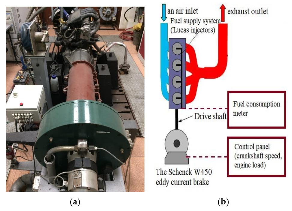
- The Schenck W450 eddy current brake with a controller allowing to obtain a constant rotational speed of the engine,
- -
- “The servomotor for controlling the injection pump,
- -
- The air consumption measurement system consists of a laminar flow meter type E7035 and a differential pressure meter type MK1,
- -
- The standard measurement systems for engine crankshaft rotational speed, torque, fuel consumption, oil and coolant temperature, and other devices that meet the requirements of PN-88/S-02005,
- -
- A device for determining the injector opening pressure, produced by L. Hartridge Ltd.,
- -
- A device for measuring the throughput of nozzles according to ISO 4010” [25].
- -
- Measurement throughput of brand-new nozzles by ISO 4010,
- -
- “Setting the injector opening pressure by the requirements of the CEC PF-023 procedure and mounting them on the engine” [25],
- -
- Conducting a 10 h test trial by the CEC PF-023 procedure,
- -
- Measurement throughput of dismantled and contaminated nozzles by ISO 4010.
- First phase: 1200 ± 30 rpm with an engine load of 10 ± 2 Nm for 30 s;
- Second phase: 3000 ± 30 revolutions per minute with an engine load of 50 ± 2 Nm for 60 s;
- Third phase: 1300 ± 30 rpm with an engine load of 35 ± 2 Nm for 60 s;
- Fourth phase: 1850 ± 30 rpm with an engine load of 50 ± 2 Nm for 120 s.
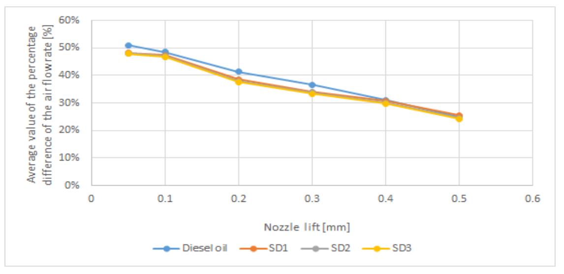
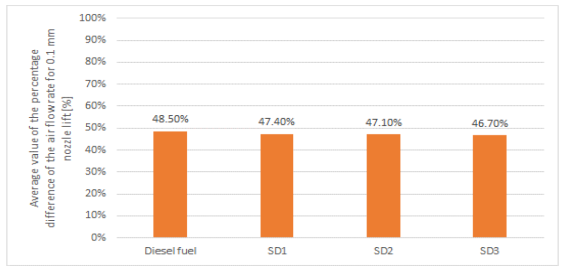
2.2. Physicochemical Parameters of Fuels
- -
- SD1—90% diesel fuel + 10% biomethanol (M-diesel),
- -
- SD2—80% diesel fuel + 20% biomethanol (M-diesel),
- -
- SD3—70% diesel fuel + 30% biomethanol (M-diesel).
3. Results
4. Discussion
5. Conclusions
Author Contributions
Funding
Institutional Review Board Statement
Informed Consent Statement
Data Availability Statement
Conflicts of Interest
References
- DIRECTIVE (EU). 2008/50/EC of the European Parliament and of the Council of 21 May 2008 on Ambient Air Quality and Cleaner Air for Europe. Available online: https://eur-lex.europa.eu/legal-content/EN/TXT/PDF/?uri=CELEX:32008L0050&from=PL (accessed on 8 September 2021).
- DIRECTIVE (EU). 2018/2001 of the European Parliament and of the Council of 11 December 2018 on the Promotion of the Use of Energy from Renewable Sources. Available online: https://eur-lex.europa.eu/legal-content/EN/TXT/PDF/?uri=CELEX:32018L2001&from=PL (accessed on 8 September 2021).
- Stanik, W. Badania poliizobutylenobursztynoimidów w zakresie oceny użytkowej dodatków detergentowo-dyspergujących do paliw silnikowych. Prace Naukowe Instytutu Nafty Gazu. 2015, 206, 1–221. (In Polish) [Google Scholar]
- Pundir, B.; Singal, S.; Gondal, A. Diesel Fuel Quality: Engine Performance and Emissions; SAE Technical Paper 942020, SAE International: Warrendale, PA, USA, 1994. [Google Scholar] [CrossRef]
- Quigley, R.; Barbour, R.; Panesar, A.; Arters, D. A review of fuel and additive performance in the new CEC F-98-08 DW10 injector fouling test. In Proceedings of the 7th International Colloquium FUELS 2009, Ostfildern, Germany, 14–15 January 2009. [Google Scholar]
- Watkinson, A.P.; Wilson, D.I. Chemical reaction fouling: A review. Exp. Therm. Fluid Sci. 1997, 14, 315–469. [Google Scholar] [CrossRef]
- Caprotti, R. Harm Free Use of Diesel Additives; SAE Technical Paper 982569, SAE International: Warrendale, PA, USA, 1998. [Google Scholar] [CrossRef]
- Leedham, A.; Caprotti, R.; Graupner, O.; Klaua, T. Impact of Fuel Additives on Diesel Injector Deposits; SAE Technical Paper 2004-01-2935, SAE International: Warrendale, PA, USA, 2004. [Google Scholar] [CrossRef]
- Tang, J.; Pischinger, S.; Grütering, U.; Keck, J. Influence on the Formation of Deposits on Injection Nozzles in Direct–Injection Diesel Engine. MTZ Worldw. 2008, 69, 64–69. [Google Scholar] [CrossRef]
- Caprotti, R.; Bhatti, N.; Balfour, G. Deposit Control in Modern Diesel Fuel Injection Systems. SAE Int. J. Fuels Lubr. 2010, 3, 901–915. [Google Scholar] [CrossRef]
- Caprotti, R.; Breakspear, A.; Graupner, O.; Klaua, T.; Kohnen, O. Diesel Injector Deposits Potential in Future Fueling Systems; SAE Technical Paper 2006-01-3359, SAE International: Warrendale, PA, USA, 2006. [Google Scholar] [CrossRef]
- Hawthorne, M.; Roos, J.W.; Openshaw, M.J. Use of Fuel Additives to Maintain Modern Diesel Engine Performance with Severe Test Conditions; SAE Technical Paper 2008-01-1806, SAE International: Warrendale, PA, USA, 2008. [Google Scholar] [CrossRef]
- Birgel, A.; Ladommatos, N.; Aleiferis, P.; Zülch, S.; Milovanovic, N.; Lafon, V.; Orlovic, A.; Lacey, P.; Richards, P. Deposit Formation in the Holes of Diesel Injector Nozzles: A Critical Review; SAE Technical Paper 2008-01-2383, SAE International: Warrendale, PA, USA, 2008. [Google Scholar]
- Birgel, A.; Ladommatos, N.; Aleiferis, P.; Milovanovic, N.; Lacey, P.; Richards, P. Investigations on Deposit Formation in the Holes of Diesel Injector Nozzles; SAE Technical Paper 2011-01-1924, SAE International: Warrendale, PA, USA, 2012. [Google Scholar]
- Struś, M. Assessment of the Influence of Biofuels on Selected Operational Properties of Compression Ignition Engines; Oficyna Wydawnicza Politechniki Wrocławskiej: Wrocław, Poland, 2012. (In Polish) [Google Scholar]
- Paulauskiene, T.; Bucas, M.; Laukinaite, A. Alternative fuels for marine applications: Biomethanol-biodiesel-diesel blends. Fuel 2019, 248, 161–167. [Google Scholar] [CrossRef]
- Tsita, K.; Kiartzis, S.; Ntavos, N.; Pilavachi, P. Next generation biofuels derived from thermal and chemical conversion of the Greek transport sector. Therm. Sci. Eng. Prog. 2020, 17, 100387. [Google Scholar] [CrossRef]
- Jamrozik, A.; Tutak, W.; Gnatowska, R.; Nowak, Ł. Comparative Analysis of the Combustion Stability of Diesel-Methanol and Diesel-Ethanol in a Dual Fuel Engine. Energies 2019, 12, 971. [Google Scholar] [CrossRef] [Green Version]
- Niculescu, R.; Clenci, A.; Iorga-Siman, V. Review on the Use of Diesel–Biodiesel–Alcohol Blends in Compression Ignition Engines. Energies 2019, 12, 1194. [Google Scholar] [CrossRef] [Green Version]
- Iliev, S. A Comparison of Ethanol and Methanol Blending with Gasoline Using a 1-D Engine Model. Procedia Eng. 2015, 100, 1013–1022. [Google Scholar] [CrossRef] [Green Version]
- Kurczyński, D.; Łagowski, P.; Wcisło, G. Experimental study into the effect of the second-generation BBuE biofuel use on the diesel engine parameters and exhaust composition. Fuel 2020, 284, 118982. [Google Scholar] [CrossRef]
- Sequino, L.; Belgiorno, G.; Di Blasio, G.; Mancaruso, E.; Beatrice, C.; Vaglieco, B.M. Assessment of the New Features of a Prototype High-Pressure “Hollow Cone Spray” Diesel Injector by Means of Engine Performance Characterization and Spray Visualization; SAE Technical Paper 2018-01-1697, SAE International: Warrendale, PA, USA, 2018. [Google Scholar] [CrossRef]
- Beatrice, C.; Belgiorno, G.; Di Blasio, G.; Mancaruso, E.; Sequino, L.; Vaglieco, B.M. Analysis of a Prototype High-Pressure “Hollow Cone Spray” Diesel Injector Performance in Optical and Metal Research Engines; SAE Technical Paper 2017-24-0073, SAE International: Warrendale, PA, USA, 2017. [Google Scholar] [CrossRef]
- Mikkonen, S.; Tenhunen, E. Deposits in Diesel Fuel-Injection Pumps Caused by In-compatibility of Fuel and Oil Additives; SAE Technical Paper 872119, SAE International: Warrendale, PA, USA, 1987. [Google Scholar] [CrossRef]
- Orliński, P.; Wojs, M.K.; Bednarski, M.; Sikora, M. Evaluation of the effect of the addition of bioethanol to gas oil on coking diesel engine injector terminals. Combust. Engines 2019, 178, 71–75. [Google Scholar] [CrossRef]
- Pehan, S.; Jerman, M.S.; Kegl, M.; Kegl, B. Biodiesel influence on tribology characteristics of a diesel engine. Fuel 2009, 88, 961–1152. [Google Scholar] [CrossRef]
- Arpaia, A.; Catania, A.E.; d’Ambrosio, S.; Ferrari, A.; Luisi, S.P.; Spessa, E. Injector Coking Effects on Engine Performance and Emissions. In Proceedings of the Internal Combustion Engine Division Fall Technical Conference, Lucerne, Switzerland, 27–30 September 2009; Volume 43635, pp. 229–241. [Google Scholar]
- Peterson, C.L. Vegetable Oil as a Diesel Fuel: Status and Research Priorities. Trans. ASAE 1986, 29, 1413–1422. [Google Scholar] [CrossRef]
- Barker, J.; Richard, P.; Snape, C.; Meredith, W. Diesel Injector Deposits—An Issue that Has Evolved with Engine Technology; SAE Technical Paper 2011-01-1923, SAE International: Warrendale, PA, USA, 2011. [Google Scholar] [CrossRef]
- Aradi, A.A.; Colucci, W.J.; Scull, H.M.; Openshaw, M.J. A Study of Fuel Additives for Direct Injection Gasoline (DIG) Injector Deposit Control; SAE Technical Paper 2000-01-2020, SAE International: Warrendale, PA, USA, 2000. [Google Scholar] [CrossRef]


| Name of Parameter | Engine Parameter | |
|---|---|---|
| No. of Cyls. & Arrangement | 4-cylinder | |
| Valve Mechanism | two-valve per cylinder engine | |
| Displacement | [cm3] | 1905 |
| Max. Output | [kW @ rpm] | 47 @ 4600 |
| Max. Torque | [N·m @ rpm] | 118 @ 2000 |
| Parameter | Unit | Diesel Fuel 1 | Biomethanol |
|---|---|---|---|
| Cetane number | - | 51.4 | 6 |
| Net calorific value | MJ/kg | 42.5 | 19.9 |
| Density at 15 °C | g/cm3 | 0.838 | 0.792 |
| Viscosity at. 40 °C | mm2/s | 2.91 | 0.74 |
| Surface tension (20 °C) | N/m | 3.64 × 10⁻² | - |
| Flash point | °C | 102 | - |
| Cloud point | °C | −17 | - |
| Cold filter plugging point (CFPP) | °C | −35 | - |
| Sulfur content | mg/kg | 9 | - |
| Water content | mg/kg | 43.8 | - |
| Total solid contamination | mg/kg | 5 | - |
| Carbon residue (on 10% distillation residue) | %(m/m) | 0.01 | - |
| Copper strip corrosion | class | 1 | - |
| Parameter | Unit | Result | ||
|---|---|---|---|---|
| SD1 | SD2 | SD3 | ||
| Flash point (open crucible) | °C | 33 | 32 | 23 |
| Cloud point | °C | <+22 | <+23 | <+27 |
| Density at 15 °C | kg/m3 | 833.5 | 829.2 | 823.9 |
| Viscosity at. 40 °C | mm2/s | 2.66 | 2.41 | 2.12 |
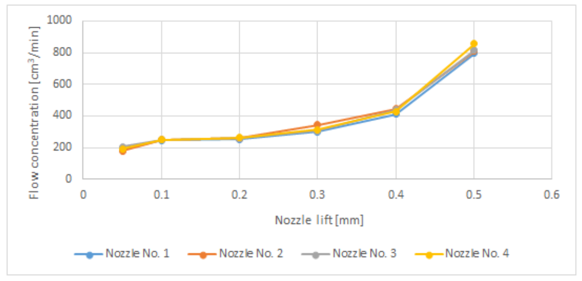
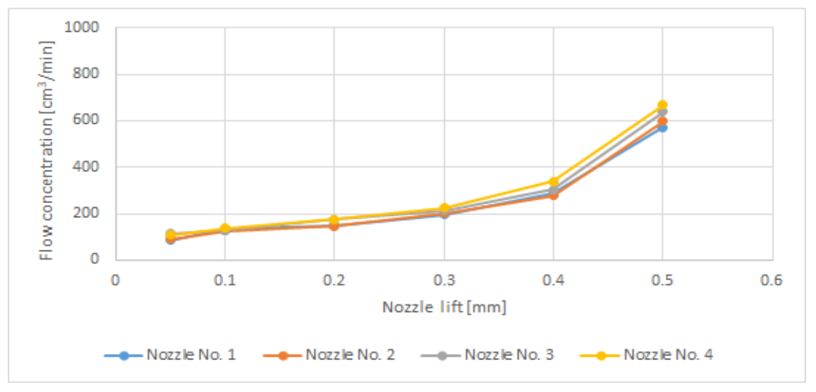
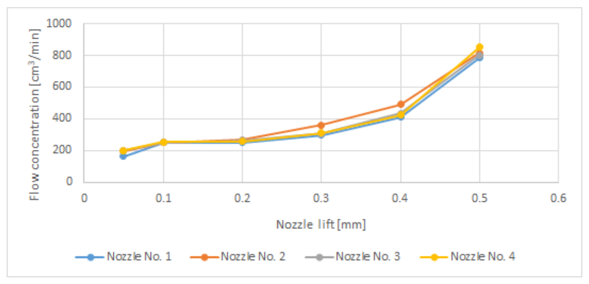
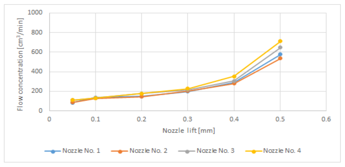
| Nozzle Lift [mm] | Nozzle No. 1 | Nozzle No. 2 | Nozzle No. 3 | Nozzle No. 4 | ||||
|---|---|---|---|---|---|---|---|---|
| Before Test | After Test | Before Test | After Test | Before Test | After Test | Before Test | After Test | |
| Diesel fuel | ||||||||
| 0.05 | 199 | 90.4 | 199 | 88.8 | 214.5 | 118.8 | 221.8 | 111.9 |
| 0.1 | 246.5 | 130 | 245.1 | 123.4 | 245.8 | 127.1 | 256.6 | 131.1 |
| 0.2 | 251.5 | 145.2 | 281.5 | 140.1 | 262.9 | 173.3 | 281.5 | 171.6 |
| 0.3 | 301.3 | 181.5 | 361 | 198.2 | 310.4 | 209.7 | 312.5 | 221.1 |
| 0.4 | 410.5 | 280.5 | 498 | 278.8 | 435.9 | 283.6 | 429.2 | 371.3 |
| 0.5 | 793 | 561 | 840.5 | 640.8 | 808.5 | 528 | 856.1 | 755.7 |
| SD1 | ||||||||
| 0.05 | 196.3 | 102 | 196.2 | 101.5 | 212.6 | 108.9 | 221.7 | 115.7 |
| 0.1 | 245.3 | 133.1 | 245 | 124.9 | 244.6 | 128.2 | 245.4 | 129.9 |
| 0.2 | 250.2 | 146.6 | 278.9 | 161.3 | 261.7 | 174.9 | 277.9 | 173.1 |
| 0.3 | 319.3 | 193 | 349.8 | 196.8 | 305.8 | 211.4 | 310.7 | 242.8 |
| 0.4 | 428.9 | 283 | 489.6 | 271.3 | 435 | 289.7 | 423.5 | 375.6 |
| 0.5 | 798.8 | 624.1 | 824 | 571.7 | 849.7 | 612.8 | 885.9 | 693.4 |
| SD2 | ||||||||
| 0.05 | 184.7 | 83.8 | 177.6 | 89.3 | 204.1 | 114.8 | 192.3 | 107.7 |
| 0.1 | 247.1 | 134.2 | 249.8 | 125.9 | 248.4 | 129.2 | 248.2 | 135.9 |
| 0.2 | 251.9 | 147.8 | 260 | 144.7 | 260.5 | 176.3 | 263 | 174.5 |
| 0.3 | 299.7 | 194.5 | 342.3 | 201.4 | 308 | 213.2 | 312.9 | 224.8 |
| 0.4 | 411.7 | 285.2 | 444 | 276.5 | 438 | 302.1 | 426.5 | 337.8 |
| 0.5 | 796.4 | 572.4 | 810 | 597.6 | 816.8 | 639.7 | 856.3 | 667 |
| SD3 | ||||||||
| 0.05 | 163.9 | 85 | 196.6 | 88.4 | 201.2 | 112.2 | 201.2 | 112 |
| 0.1 | 248.9 | 137 | 248.8 | 128.5 | 249.1 | 134.9 | 253.9 | 132.6 |
| 0.2 | 250.7 | 149.6 | 268.5 | 144.5 | 262.2 | 178.5 | 258.5 | 176.8 |
| 0.3 | 298.1 | 197 | 360.5 | 204 | 306.4 | 215.9 | 311.3 | 227.8 |
| 0.4 | 409.6 | 289 | 490.5 | 279.9 | 435.8 | 306 | 424.4 | 352.5 |
| 0.5 | 786.4 | 578 | 815.6 | 536 | 802.8 | 646 | 852 | 711 |
Publisher’s Note: MDPI stays neutral with regard to jurisdictional claims in published maps and institutional affiliations. |
© 2022 by the authors. Licensee MDPI, Basel, Switzerland. This article is an open access article distributed under the terms and conditions of the Creative Commons Attribution (CC BY) license (https://creativecommons.org/licenses/by/4.0/).
Share and Cite
Orliński, P.; Laskowski, P.; Zimakowska-Laskowska, M.; Mazuruk, P. Assessment of the Impact of the Addition of Biomethanol to Diesel Fuel on the Coking Process of Diesel Engine Injectors. Energies 2022, 15, 688. https://doi.org/10.3390/en15030688
Orliński P, Laskowski P, Zimakowska-Laskowska M, Mazuruk P. Assessment of the Impact of the Addition of Biomethanol to Diesel Fuel on the Coking Process of Diesel Engine Injectors. Energies. 2022; 15(3):688. https://doi.org/10.3390/en15030688
Chicago/Turabian StyleOrliński, Piotr, Piotr Laskowski, Magdalena Zimakowska-Laskowska, and Paweł Mazuruk. 2022. "Assessment of the Impact of the Addition of Biomethanol to Diesel Fuel on the Coking Process of Diesel Engine Injectors" Energies 15, no. 3: 688. https://doi.org/10.3390/en15030688
APA StyleOrliński, P., Laskowski, P., Zimakowska-Laskowska, M., & Mazuruk, P. (2022). Assessment of the Impact of the Addition of Biomethanol to Diesel Fuel on the Coking Process of Diesel Engine Injectors. Energies, 15(3), 688. https://doi.org/10.3390/en15030688