Article

A Quantitative Evaluation Method of Anti-Sloughing Drilling Fluid Inhibition for Deep Mudstone

1
State Key Laboratory of Petroleum Resources and Prospecting, China University of Petroleum, Beijing 102249, China
2
College of Petroleum Engineering, China University of Petroleum, Beijing 102249, China
3
Tarim Oil Field Company, Petro China, Korla 841000, China
*
Author to whom correspondence should be addressed.
Energies 2022, 15(3), 1226; https://doi.org/10.3390/en15031226
Submission received: 12 January 2022 / Revised: 2 February 2022 / Accepted: 4 February 2022 / Published: 8 February 2022

Abstract

:
Wellbore instability resulting from deep mudstone hydration severely restricts the development of oil and gas resources from deep reservoir in western China. Accurate evaluation of drilling fluid inhibition properties plays an important role in selecting drilling fluid that can control deep mudstone hydration and then sustain wellbore stability. The previous evaluations are conducted by qualitative analysis and cannot consider the influence of complex hydration conditions of deep mudstone (high temperature, high pressure and flushing action). The study proposes a quantitative method to evaluate drilling fluid’s inhibition property for deep mudstone under natural drilling conditions. In this method, the cohesive strength of mudstone after hydration is adopted as the inhibition index of the tested drilling fluid. An experimental platform containing a newly designed HPHT (High pressure and high temperature) hydration experiment apparatus and mechanics characterization of mudstone after hydration based on scratch test is proposed to obtain the current inhibition index of tested drilling fluid under deep well drilling environments. Based on the mechanical–chemical wellbore stability model considering strength weakening characteristics of deep mudstone after hydration, a cross-correlation between drilling fluid density (collapse pressure) and required inhibition index (cohesive strength) for deep mudstone is provided as the quantitative evaluation criterion. Once the density of tested mud is known, one can confirm whether the inhibition property of tested mud is sufficient. In this study, the JDK mudstone of a K block in western China is selected as the application object of the proposed evaluation method. Firstly, the evaluation chart, which can demonstrate the required inhibition indexes of the tested fluids quantitatively with various densities for JDK mudstone, is constructed. Furthermore, the experimental evaluations of inhibition indexes of drilling fluids taken from two wells in K block are conducted under ambient and deep-well drilling conditions, respectively. In order to show the validity and advantage of the proposed method, a comparison between the laboratory evaluation results and field data is made. Results show that the laboratory evaluation results under deep-well drilling conditions are consistent with the field data. However, the evaluation under ambient conditions overestimates the inhibition property of the tested fluid and brings a risk of wellbore instability. The developed quantitative method can be a new way to evaluate and optimize the inhibition property of drilling fluid for deep mudstone.

1. Introduction

The exploration and development of oil and gas resources from a deep reservoir in western China is showing great potential. However, wellbore instability resulting from deep mudstone hydration is still a troublesome problem to drilling engineers, which causes tremendous economic losses. The capability of drilling fluid to inhibit deep mudstone hydration is a key indicator of wellbore stability. To accurately evaluate drilling fluid inhibition property is a prerequisite for choosing the drilling fluid with good performance and then sustaining wellbore stability.
In recent years, many evaluation methods of drilling fluid inhibition property are proposed as summarized in Table 1. Based on the analysis of evaluation principles, these evaluation methods can be clarified into two types. (1) Methods to evaluate the physical and mechanical properties of solid medium after hydration (swelling, dispersion and strength): ① hot rolling dispersion test [1,2,3]; ② slake durability evaluation [2,4,5]; ③ swelling test [5,6,7,8]; ④ bulk hardness test [4,9]; ⑤ water adsorption test [10]; ⑥ mud ball immersing test [3,11]; ⑦ particle size distribution test [11,12]; ⑧ shale stability index test [8,13]; ⑨ cohesive strength test (Energy Sector Standard of the People’s Republic of China: NB/T 10121-2018) [14]. (2) Methods to evaluate the chemical and rheological properties of liquid medium after hydration: ① rheological evaluation [15]; ② high-speed centrifugation [16,17]; ③ flocculation experiment [18,19]; ④ water separating ratio test [16]; ⑤ specific surface area test with methylene blue solution [20,21]; ⑥ capillary suction time test [22,23,24]; ⑦ accretion test [2,9]; ⑧ zeta potential test [8,25]; ⑨ X-ray diffraction analysis [15,25].
Although these common evaluation methods of drilling fluid inhibition performance have been widely used in the oil and gas industry, there are still many limitations to overcome, especially for deep mudstone. (1) The complex hydration conditions in a deep well cannot be provided (as shown in Table 1). However, numerous studies have demonstrated that well drilling conditions have a significant impact on the property of drilling fluid and the rock–fluid interaction [24,26,27,28,29,30]. As for deep mudstone in western China, a harsher and more hostile hydration environment will be encountered such as high temperature (~20 °C), high drilling differential pressure (~40 MPa) and flushing action of drilling fluid. Therefore, it is necessary to consider the effect of complex drilling conditions on the evaluation of drilling fluid inhibition property for deep mudstone. (2) Quantitative evaluation basis of drilling fluid inhibition property is not proposed. Previous qualitative/empirical evaluation methods are difficult to use to definitely identify the safe value of inhibition index. (3) The coupling of mechanical and chemical actions of drilling fluid on sustaining wellbore stability is not involved in the current estimation of drilling fluid inhibition property.
In this study, an experimental platform containing a newly designed HPHT hydration experiment and mechanical characterization of mudstone based on a scratch test is adopted to obtain the value of inhibition index of drilling fluid under deep-well drilling conditions. In addition, a cross-correlation between drilling fluid density (collapse pressure) and the matching inhibition index (cohesive strength) for deep mudstone, which is revealed by the mechanical–chemical wellbore stability model, is provided as the quantitative evaluation criterion. Based on the above works, a quantitative evaluation method for the inhibition property of drilling fluid for deep mudstone is proposed. In order to validate the proposed method, a comparison analysis of the laboratory evaluation results under different conditions (deep-well drilling condition and ambient condition) and field data of JDK mudstone (depth: about 5200–6800 m) of the K block in western China is conducted.

2. Methodology

The heart of the matter for the previous evaluation methods can be divided into two points. ① How to obtain inhibition property of drilling fluid under deep-well drilling conditions, and ② how to achieve the quantitative evaluation of drilling fluid inhibition property for deep mudstone. In order to overcome the two difficult problems above, the main work in this new proposed method are divided into two parts (as shown in Figure 1). ① The first part is to develop an experimental method of deep mudstone hydration characterization. In the first part, a newly designed hydration experimental apparatus is adopted to provide deep-well drilling conditions (high temperature, high pressure and flushing action of drilling fluid). Furthermore, the continuous scratch test is used to obtain the cohesive strength of mudstone after hydration, which can be regarded as the inhibition index of drilling fluid. ② The second part is to propose a method that can determine the quantitative correlation between drilling fluid density (collapse pressure) and required inhibition index (cohesive strength). Based on the mechanical–chemical wellbore stability model, wellbore collapse pressure, which is the critical minimum mud density for preventing wellbore collapse, is related to rock cohesive strength. In the second part, considering the weakening characteristics of the strength property of deep mudstone at different degrees of hydration, the correlation chart of drilling fluid density and matching inhibition index (cohesive strength) for deep mudstone is constructed. Once the density of tested drilling fluid is known, the required inhibition index for deep mudstone can be confirmed.

2.1. Method of Hydration Characterization of Deep Mudstone

In our previous study [30], the new experimental platform containing a HPHT (high temperature and high pressure) hydration experiment and rock mechanical characterization based on scratch test is constructed to study the effect of hydration on rocks’ mechanical properties. In this paper, because cohesive strength of mudstone after hydration can be regarded as the inhibition index of the drilling fluid, the experimental platform is proposed as a new experimental method to obtain inhibition performance of drilling fluid under deep-well drilling conditions.
(1)
HPHT hydration experimental apparatus
As shown in Figure 2, the new designed HPHT experimental apparatus consists of hydration test section and core flow test section. A hydration test section, which can provide the hydration of several samples with different shapes under complex environments (maximum surrounding temperature of 200 °C, maximum surrounding pressure of 60 MPa and flushing action of fluid), is adopted in this study. The hydration test section is mainly made up of hydration kettle, electrical heating system, stirring system, pressure pump, monitoring system and data acquisition system.
(2)
Estimation of rock mechanical properties based on continuous scratch test
After immersed in tested fluid, the mudstone sample is used to evaluate the performance of tested fluid by strength test. Firstly, the uniaxial compressive strength (UCS) and internal friction angle are estimated by continuous scratch test with a sharp cutter and blunt cutter. The detailed principle and procedure are demonstrated by previous studies [30,31,32,33]. In addition, the Mohr–Coulomb criterion (as shown in Equation (1)), which reveals the relation between UCS, internal friction angle and cohesive strength is adopted to obtain the cohesive strength (inhibition index) in this study. The TerraTek continuous scratch test system used in this study is shown in Figure 3.
C = U C S × ( 1 sin φ ) 2 cos φ
where C is rock cohesive strength, MPa; φ is rock internal friction angle, °; UCS is rock uniaxial compressive strength, MPa.

2.2. Method of Determining Correlation between Drilling Fluid Density and Matching Inhibition Index

Preventing wellbore collapse relies not only on the chemical property of drilling fluid (inhibition performance) but also on mechanical support from drilling fluid density. Poor performance of drilling fluid in inhibiting mudstone hydration always requires adjustment of drilling fluid density, which provides wellbore collapse pressure. Based on the mechanical–chemical wellbore stability model, the relation between drilling fluid density (collapse pressure) and matching inhibition index (cohesive strength) can be constructed and then regarded as the quantitative criterion of estimating drilling fluid inhibition properties. The method of determining the quantitative relation consists of three parts as follows.
(1)
Framework of wellbore stability model
In this study, in order to ensure the popularization and application of the developed evaluation method, the framework of mechanical wellbore stability model, which is simple and widely used in drilling engineering, is selected to describe the relationship between collapse pressure (drilling fluid density) and cohesive strength (matching inhibition index).
The equations for stress distribution around wellbore are shown in Equation (2) [34,35].
{ σ r = σ x x + σ y y 2 ( 1 R w 2 r 2 ) + σ x x σ y y 2 ( 1 + 3 R w 4 r 4 4 R w 2 r 2 ) cos 2 θ + τ x y ( 1 + 3 R w 4 r 4 4 R w 2 r 2 ) sin 2 θ + R w 2 r 2 p m + δ [ a ( 1 2 ν ) 2 ( 1 ν ) ( 1 R w 2 r 2 ) ϕ ] ( p m p p ) σ θ = σ x x + σ y y 2 ( 1 + R w 2 r 2 ) σ x x σ y y 2 ( 1 + 3 R w 4 r 4 ) cos 2 θ τ x y ( 1 + 3 R w 4 r 4 ) sin 2 θ R w 2 r 2 p m + δ [ a ( 1 2 ν ) 2 ( 1 ν ) ( 1 + R w 2 r 2 ) ϕ ] ( p m p p ) σ z = σ z z 2 ν [ ( σ x x σ y y ) R w 2 r 2 cos 2 θ + 2 τ x y R w 2 r 2 sin 2 θ ] + δ [ a ( 1 2 ν ) 2 ( 1 ν ) ϕ ] ( p m p p ) τ r θ = σ y y σ x x 2 ( 1 + 2 R w 2 r 2 3 R w 4 r 4 ) sin 2 θ + τ x y ( 1 + 2 R w 2 r 2 3 R w 4 r 4 ) cos 2 θ τ θ z = τ y z ( 1 + R w 2 r 2 ) cos θ τ x z ( 1 + R w 2 r 2 ) sin θ τ r z = τ x z ( 1 R w 2 r 2 ) cos θ + τ y z ( 1 R w 2 r 2 ) sin θ
where σ r is radial normal borehole stress, MPa; σ θ is circumferential normal borehole stress, MPa; σ z is axial normal borehole stress, MPa; τ r θ , τ θ z , τ r z are three components of the shear stress, MPa; σ x x , σ y y , σ z z are in situ normal stresses rotated to the borehole coordinate reference frame, MPa; τ x y , τ y z , τ x z are in situ shear stresses rotated to the borehole coordinate reference frame, MPa; R w is the radius of the borehole, m; r is radial distance away from wellbore, m; p m is the downhole pressure, MPa; p p is the formation pore pressure, MPa; θ is the point location angle, °; ν is Poisson’s ratio of the formation, dimensionless; a is Biot effective stress coefficient, dimensionless; ϕ is formation porosity, %.
The stress distribution around wellbore also can be expressed by in situ stresses ( σ H , maximum horizontal stress; σ h , minimum horizontal stress; σ v , vertical stress) through a number of coordinate transformations. The detailed transformations can be found in previous studies [36,37].
The shear failure of rock is described by Mohr–Coulomb strength criterion (as shown in Equation (3)).
σ 1 [ σ 3 + 2 ( C + σ 3 tan φ ) ( ( tan φ ) 2 + 1 + tan φ ) ] = 0
where σ 1 , σ 3 are maximum principal stress and minimum principal stress, respectively, MPa; C is cohesive strength of rock, MPa; φ is internal friction angle of rock, °.
By coupling Equation (2) with Equation (3), we can obtain the minimum mud weight required to prevent wellbore collapse for mudstone with a given strength. However, it must be noted that chemical effect of hydration on deep mudstone strength properties and wellbore stability is not considered in the above model and needs to be updated.
(2)
Deterioration model of mudstone mechanical properties after hydration
Based on the developed experimental apparatus, the empirical model describing the strength weakening characteristics of mudstone at various levels of hydration under well drilling conditions can be constructed. As shown in Equation (4), the strength change of mudstone after hydration is a function of its uptake water content w ( r , t ) , which is related to the radial distance from wellbore (r) and hydration time (t). The detailed descriptions about w(r,t) in [38,39] are used in this study.
C ( w ( r , t ) ) = C i A × ( w ( r , t ) w i ) φ ( w ( r , t ) ) = φ i B × ( w ( r , t ) w i )
where C ( w ( r , t ) ) , C i are cohesive strength of mudstone after and before hydration, respectively, MPa; φ ( w ( r , t ) ) , φ i are internal friction angle of mudstone after and before hydration, respectively, °; w ( r , t ) , w i are uptake water content of mudstone after and before hydration, respectively, %; A , B are the empirical coefficients determined by experimental data.
Therefore, Equation (3) can be updated as follows
σ 1 [ σ 3 + 2 ( C ( w ( r , t ) ) + σ 3 tan φ ( w ( r , t ) ) ) ( ( tan φ ( w ( r , t ) ) ) 2 + 1 + tan φ ( w ( r , t ) ) ) ] = 0
(3)
Quantitative relation between drilling fluid density and matching inhibition index
According to the above wellbore stability model considering strength-weakening characteristics of mudstone after hydration, the drilling fluid densities required to prevent wellbore collapse for mudstones with different hydration levels (different cohesive strengths) can be calculated. In addition, when a certain extent of failure regions around the wellbore can be allowed (acceptable maximum borehole enlargement rate is generally 15% in well-drilling engineering), the relationship of the required drilling fluid density, the matching inhibition index and the borehole enlargement rate (the ratio of the difference between borehole diameter and drilling bit diameter to the drilling bit diameter) can also be constructed.

2.3. Evaluation Procedure of Drilling Fluid Inhibition for Deep Mudstone

As shown in Figure 4, the detailed procedure of estimating drilling fluid inhibition property for deep mudstone is divided into two steps.
(1)
Obtaining the cross-correlation chart of drilling fluid density and inhibition index for deep mudstone
On the basis of the method described in Section 2.2, the first stage is to develop the strength-weakening model of deep mudstone at various levels of hydration, and the next is to construct the correlation chart of the required drilling fluid density, matching inhibition index and borehole enlargement rate.
  • Establishing the strength deterioration model of deep mudstone after hydration
The developed HPHT experimental apparatus is utilized to conduct the hydration of deep mudstone for different times under deep-well drilling conditions. Furthermore, the mechanical properties of deep mudstone after hydration are estimated based on scratch test. At the same time, the uptake water content of mudstone is obtained by using a weighting method. Therefore, the empirical model describing the chemical effect of hydration on deep mudstone strength parameters is updated.
2.
Constructing the quantitative correlation chart
According to the chemical–mechanical wellbore stability model for deep mudstone, the relationships between required drilling fluid density and matching inhibition index for different extent of wellbore collapse (borehole enlargement rate) can be constructed and are regarded as the quantitative evaluation criterion for drilling fluid inhibition property.
(2)
Evaluating inhibition property of drilling fluid
  • Obtaining the required inhibition index of the tested drilling fluid based on the above correlation chart
According to the requirement of borehole enlargement rate in drilling engineering and the density of the tested drilling fluid, the required inhibition index for sustaining the wellbore stability in deep mudstone can be confirmed from the above correlation chart.
2.
Estimating the current inhibition index of the tested drilling fluid for deep mudstone
The mudstone sample is immersed in the tested drilling fluid under the well drilling conditions for a constant time, which can provide fully hydration. Additionally, the cohesive strength of mudstone after hydration is then estimated as the current inhibition index of the tested drilling fluid. All of the above works is conducted on the developed experimental platform.
3.
Judging the inhibition property of the tested drilling fluid
By comparing the above two kinds of inhibition indexes, it can be changed whether the tested drilling fluid have a good performance in terms of the inhibition property. As shown in Figure 4, if the current tested drilling fluid has a risk of causing wellbore instability, adjustments of drilling fluid density and inhibition property are both available choices.

3. Application and Analysis

The problem of downhole fall-blocks (as shown in Figure 5) and pipe-stuck accidents are frequent in the JDK mudstone formation of the K block (depth: about 5200–6800 m). Therefore, the application of the proposed evaluation method in this study is focused on the JDK mudstone in the K block.

3.1. Detailed Design and Preparation for Evaluation

According to the above evaluation procedure, the main work consists of three parts: experiment on the hydration characterization of the JDK mudstone, establishment of the evaluation chart for JDK mudstone in K block and inhibition property evaluations of drilling fluids taken from the engineering field. The detailed plan and preparation of the above work are described as follows.
(1)
Hydration characterization of JDK mudstone
In order to more accurately describe the weakening characteristics of mechanical properties of JDK mudstone after hydration (strength deterioration model), two samples of JDK mudstone outcrops were prepared. The hydration times of mudstones were 0, 2, 4, 8, 12, 24 and 48 h, respectively. Based on the geological information of JDK mudstone formation in K block, the temperature and pressure of immersing mudstones in poly-potassium mud were 130 °C and 23 MPa, respectively. In addition, for the mechanical test, the sharp cutter with scratching depth of 0.16 mm and blunt cutter with scratching depth of 0.06–0.12 mm were used in this study.
(2)
Establishment of the evaluation chart for JDK mudstone formation in the K block
The establishment of evaluation chart of drilling fluid inhibition property for JDK mudstone in K block is based on the calculation of the wellbore stability model considering the strength weakening characteristics of the JDK mudstone. Basic input parameters of the mechanical–chemical model are listed in Table 2. The mathematical calculations in this paper are conducted in MATLAB (The MathWorks, Inc., Natick, MA, USA).
(3)
Case study: Inhibition evaluations of drilling fluids taken from engineering field
In this study, the inhibition performance of drilling fluids of well K 8-13 and well K 9-3 were estimated using the proposed method. In order to study the influence of the surrounding environments on evaluation results, the evaluation of the inhibition property of drilling fluids under both deep-well drilling conditions (130 °C and 23 MPa) and ambient conditions (50 °C and normal pressure) are conducted. In addition, the comparisons between laboratory evaluation results and field data are designed to confirm whether the developed method is feasible and valid.

3.2. Evaluation Chart of Drilling Fluid Inhibition Index for JDK Mudstone Formation

3.2.1. Hydration Characterization of Mudstone in JDK Formation

Two samples of JDK mudstones with different hydration levels under deep-well drilling conditions are shown in Figure 6. Because continuous scratch test is a kind of nondestructive method, the mechanical parameters of mudstone after hydration can be estimated using the same sample. Compared to the traditional compressive test (destructive test), it can avoid the interference of experimental sample and reveal the real hydration characteristics of deep mudstone.
The hydration characteristics of JDK mudstones under deep-well drilling conditions are presented in Figure 7. The uptake water contents of JDK mudstones after hydration increase with soaking time and reach the maximum value (0.045–0.06) when the soaking time is greater than 24 h. The changes in strength parameters of JDK mudstones after hydration have similar trends, which include a decrease in the soaking time until fully hydration, including uniaxial compressive strength (UCS), internal friction angle and cohesive strength. Therefore, the hydration time of 24 h is adopted in the following inhibition evaluation experiments of tested fluids.
Based on the above experimental results, the relationships between the shear strength properties and uptake water contents of JDK mudstones are described in Figure 8. The deterioration models of mechanical properties of JDK mudstones after hydration can be concluded as per Equation (6).
C c = C i 154.67 × ( w c w i ) φ c = φ i 178.92 × ( w c w i )
where C c , φ c are current cohesive strength and internal friction angle of mudstone with a certain uptake water content, respectively, MPa; w c is the current uptake water content of mudstone after hydration.

3.2.2. Quantitative Correlation Chart of Drilling Fluid Density and Required Inhibition Index for JDK Mudstone Formation

According to the wellbore stability model updated by the strength deterioration model of JDK mudstone after hydration (as described in Equation (6)) and basic parameters listed in Table 2, the wellbore collapse regions of JDK mudstones with different hydration levels (the poorer the inhibition performance of the drilling fluid is, the higher hydration level of mudstone is and the more serious the deterioration of the mudstone cohesive strength is) can be displayed visually. For instance, the borehole enlargement distributions of JDK mudstones at different hydration levels with a given drilling fluid density (1.80 g/cm3) are shown in Figure 9. In the case of constant drilling fluid density, the wellbore collapse region (red area) enlarges gradually with the aggravation of JDK mudstone hydration caused by the poorer mud inhibition property. Based on the wellbore collapse contour map, the maximum borehole enlargement rates of JDK mudstones for different types of drilling fluid (i.e., drilling fluid density and inhibition property) can be directly revealed.
Figure 10 gives the quantitative cross-correlation of drilling fluid density and required inhibition index (cohesive strength of mudstone after immersed in tested drilling fluid) for sustaining different borehole enlargement rates in JDK mudstone. In this chart, only the data of five borehole enlargement rates, which are 0%, 5%, 10%, 15% and 20%, respectively, are presented. Based on the correlation chart, once the permissible borehole enlargement rates and tested drilling fluid densities are known, the required inhibition index of tested drilling fluid can be obtained.

3.3. Case 1: Evaluation of Drilling Fluid in Well K 8-13 for JDK Mudstone

The density of drilling fluid sample which is taken from well K 8-13 is 1.84 g/cm3. As shown in Figure 10, the blue dashed line, which represents the mud density of well K 8-13, is marked and intersects with the solid lines with asterisk markers, which represent the data of different borehole enlargement rates. Because the permissible borehole enlargement rate in drilling engineering is 15%, the required inhibition index of the current drilling fluid sample for JDK mudstone is 4.76 MPa, as indicated by the blue solid line in Figure 10.

3.3.1. Inhibition Evaluations under Deep-Well Drilling Conditions and Ambient Conditions

Figure 11 and Figure 12 show the JDK mudstone samples used in inhibition-property evaluations of drilling fluid under real well drilling conditions and ambient conditions, respectively. From the qualitative comparison between the surface flatness of mudstones immersed in same drilling fluid under different conditions, it can be found that the damage to mudstone immersed in mud under deep-well drilling conditions is more serious. In other words, the inhibition property of drilling fluid under deep-well drilling conditions is worse.
Figure 13 illustrates the quantitative evaluation results regarding the inhibition property of drilling fluid under different conditions. The blue column denotes the initial cohesive strength of mudstone and the red column denotes cohesive strength of mudstone after hydration, which represents the inhibition index of the tested drilling fluid. The data of 1#, 2# and 3# show that the inhibition property of the tested drilling fluid under deep-well drilling conditions cannot meet the required inhibition index as marked by the pink dashed line (i.e., the average value of the current inhibition index is about 3.88 MPa and less than 4.76 MPa). However, the results of 4# and 5# indicate that the current inhibition performance of the drilling fluid under ambient conditions is sufficient. Based on the contradictory results above, it can be inferred that considering the natural surrounding environments in inhibition evaluation of drilling fluid is very meaningful and necessary.

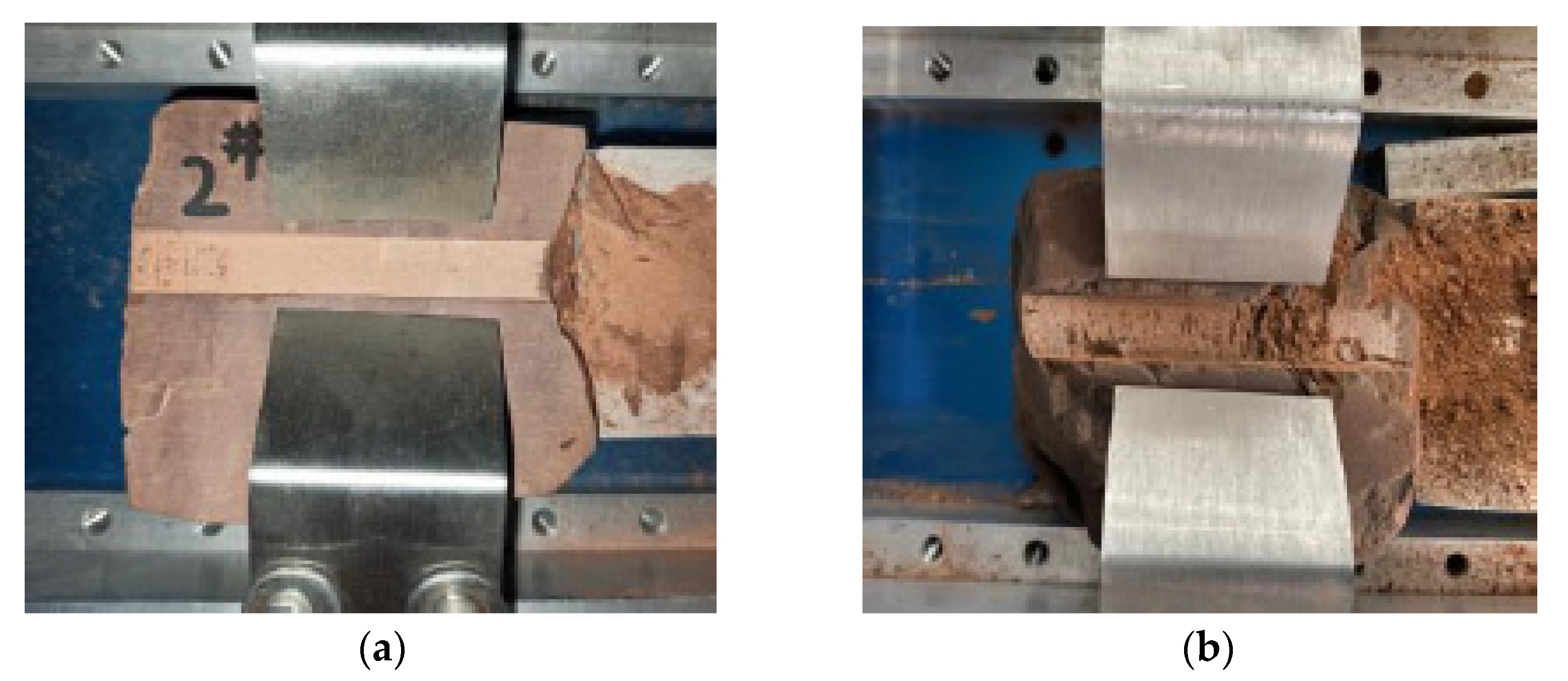
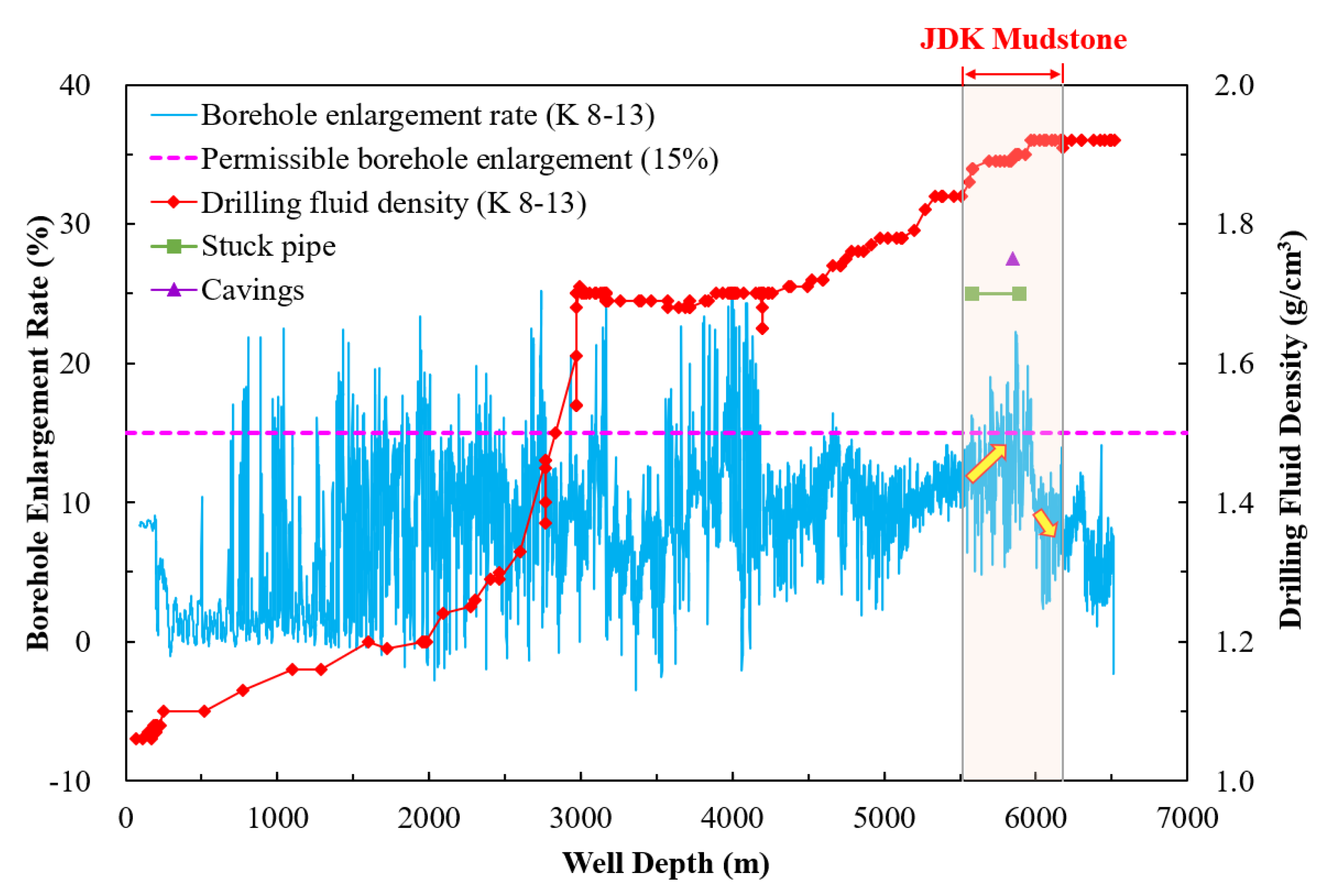
3.3.2. Field Validation

As shown in Figure 14, when the JDK mudstone formation is drilled by using lower mud density (1.84–1.90 g/cm3), the complex accidents such as stuck pipe and caving are frequent and the borehole enlargement rate always stays at a high level. This indicates that the property of the current drilling fluid (e.g., mud density and inhibition index) cannot sustain wellbore stability of the JDK mudstone. In order to control the further wellbore collapse of the JDK mudstone and prevent more serious and complex accidents, the drilling engineers adopt the widely effective method of increasing mud density. When the mud density increases to 1.92 g/cm3, the borehole enlargement rate of JDK mudstone is under 15%.
In reality, this adopted solution in the engineering field is consistent with the guidance implied by the quantitative cross-correlation chart above. As described in Figure 4, except for increasing inhibition performance of the drilling fluid, adjustment of drilling fluid density is also an available option for controlling wellbore collapse. From Figure 10, it can be inferred that the density of drilling fluid needs to be increased to about 1.92–1.93 g/cm3 if the current inhibition index of drilling fluid is not altered. Therefore, in some ways, the proposed inhibition evaluation method of drilling fluid in this paper is validated.

3.4. Case 2: Evaluation of Drilling Fluid in Well K 9-3 for JDK Mudstone

The density of the drilling fluid sample taken from well K 9-3 was 1.90 g/cm3. As presented in Figure 10, the yellow dashed line means the mud density of well K 9-3 has an intersection point with the blue solid line marked by asterisks (the data of borehole enlargement rate = 15%). The value of abscissa of the intersection point is 4.23 MPa (i.e., the required inhibition index of drilling fluid sample) as marked by the yellow solid line in Figure 10.

3.4.1. Inhibition Evaluation under Deep-Well Drilling Conditions

Figure 15 is the JDK mudstone sample used in inhibition evaluation of drilling fluid in well K 9-3 under deep-well drilling conditions. The tested drilling fluid of well K 9-3 may have a good performance in the inhibition property from the point of view of integrity of the mudstone after hydration. Additionally, the quantitative result presented in Figure 16 validates this. The current inhibition index of the tested drilling fluid taken from well K 9-3 is about 5.86 MPa and exceeds the required inhibition index.

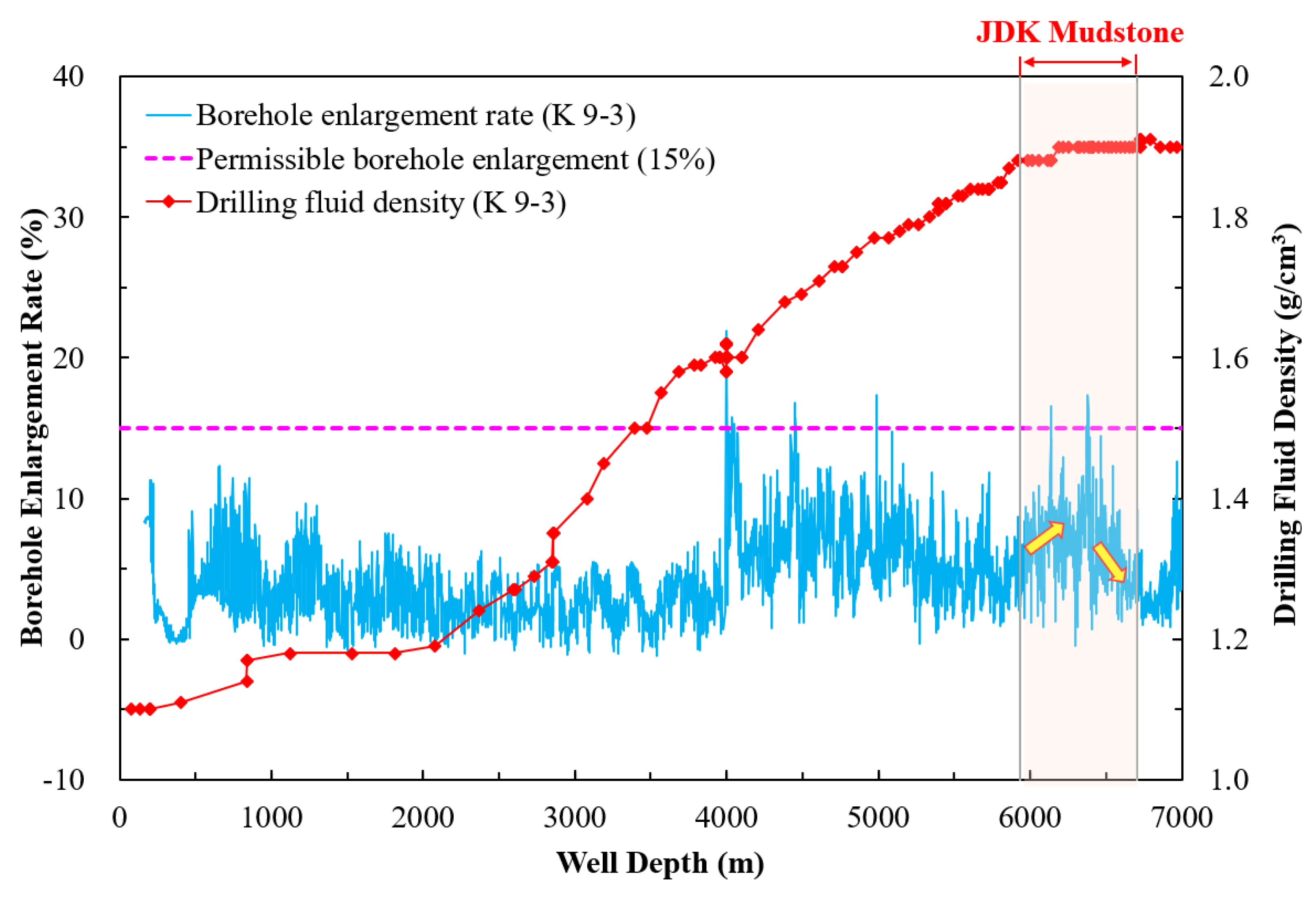
3.4.2. Field Validation

From Figure 17, it can be seen that the mud density used in drilling JDK mudstone formation is 1.88–1.90 g/cm3 and the average borehole enlargement rate is less than 10%. Especially for the well drilling process with mud density of 1.90 g/cm3, the borehole enlargement rate of JDK mudstone decreases gradually and stays within 5%. The above field data illustrate that the current inhibition index of the tested drilling fluid sample in well K 9-3 can meet the requirement of sustaining wellbore stability of JDK mudstone. This is consistent with our inhibition evaluation results provided by the proposed method.

4. Conclusions

(1)
In order to achieve the quantitative evaluation of the inhibition property of drilling fluid under deep-well drilling conditions, a new evaluation method that adopts cohesive strength of mudstone after hydration as the inhibition index of drilling fluid is proposed in this study. In this method, a newly designed HPHT hydration experiment apparatus (maximum surrounding temperature of 200 °C, maximum surrounding pressure of 60 MPa and flushing action of fluid) is developed to provide the real hydration environments in the process of drilling deep well. Additionally, a method of estimating cohesive strength of mudstone after hydration based on a scratch test is established to obtain the inhibition index of the tested drilling fluid. In addition, a cross-correlation between drilling fluid density and the matching inhibition index for deep mudstone, which is revealed by the mechanical–chemical wellbore stability model considering hydration characteristic of deep mudstone, is constructed as the quantitative evaluation criterion.
(2)
The comparison of inhibition evaluation results of drilling fluids under ambient conditions and natural well-drilling conditions illustrates that ignoring the natural surrounding environments in the process of inhibition evaluation of drilling fluid may cause overestimation of inhibition properties. Therefore, it is very necessary and meaningful to propose a new inhibition evaluation method of drilling fluid under real well-drilling conditions for wellbore stability in deep mudstone.
(3)
The evaluation results of drilling fluids taken from the well K 8-13 and well K 9-3, which are provided by the proposed evaluation method, are in line with the field data. In some ways, the developed quantitative evaluation method of inhibition property of drilling fluid for deep mudstone is validated.
(4)
The developed quantitative method can consider the coupling actions of mechanical and chemical actions of drilling fluid and provide strong support for field engineers to sustain wellbore stability through adjustments of drilling fluid density and inhibition properties.
(5)
In order to achieve the widespread application of the proposed method in drilling engineering field, our research group is trying to make a miniaturized experimental evaluation platform and standardize the evaluation procedure.

Author Contributions

Conceptualization, Y.J., Y.L. and K.B.; methodology, K.B.; software, K.B.; validation, K.B., H.L. and J.Z.; writing—original draft preparation, K.B.; writing—review and editing, K.B., Y.J. and Y.L.; visualization, K.B.; supervision, Y.J. and Y.L. All authors have read and agreed to the published version of the manuscript.

Funding

This research was funded by National Natural Science Foundation of China (General Program: No. 52074314) and National Key Research and Development Program of China (2019YFA0708303-05).

Institutional Review Board Statement

Not applicable.

Informed Consent Statement

Not applicable.

Data Availability Statement

The data presented in this study are available on request from the corresponding author.

Conflicts of Interest

The authors declare no conflict of interest.

References

  1. Aston, M.S.; Elliot, G.P. Water-based glycol drilling muds: Shale inhibition mechanisms. In Proceedings of the European Petroleum Conference, London, UK, 25–27 October 1994. [Google Scholar]
  2. Patel, A.; Stamatakis, E.; Young, S.; Cliffe, S. Designing for the future—A review of the design, development and testing of a novel, inhibitive water-based drilling fluid. In Proceedings of the AADE 2002 Technical Conference, Houston, TX, USA, 2–3 April 2002. [Google Scholar]
  3. Ghasemi, M.; Moslemizadeh, A.; Shahbazi, K.; Mohammadzadeh, O.; Zendehboudi, S.; Jafari, S. Primary evaluation of a natural surfactant for inhibiting clay swelling. J. Pet. Sci. Eng. 2019, 178, 878–891. [Google Scholar] [CrossRef]
  4. Qiu, Z.; Zhong, H.; Huang, W.; Wan, J.; Xu, J. A new method for evaluation the properties of high-performance drilling fluids. Drill. Fluid Completion Fluid 2009, 26, 58–59. [Google Scholar]
  5. Al-Arfaj, M.; Amanullah, M.; Sultan, A. Chemical and mechanical aspects of wellbore stability in shale formations: A literature review. In Proceedings of the Abu Dhabi International Petroleum Exhibition and Conference, Abu Dhabi, United Arab Emirates, 10–13 November 2014. [Google Scholar]
  6. Stephens, M.; Gomez, S.; Churan, M. Laboratory methods to assess shale reactivity with drilling fluids. In Proceedings of the 2009 National Technical Conference and Exhibition, New Orleans, LA, USA, 12–14 April 2009. [Google Scholar]
  7. Salles, F.; Bildstein, O.; Douillard, J.M.; Jullien, M.; Raynal, J.; Van, D.H. On the cation dependence of interlamellar and interparticular water and swelling in smectite clays. Langmuir 2010, 26, 5028–5037. [Google Scholar] [CrossRef]
  8. Huang, W.A.; Li, X.; Qiu, Z.S.; Jia, J.H.; Wang, Y.; Li, X. Inhibiting the surface hydration of shale formation using preferred surfactant compound of polyamine and twelve alkyl two hydroxyethyl amine oxide for drilling. J. Pet. Sci. Eng. 2017, 159, 791–798. [Google Scholar] [CrossRef]
  9. Patel, A.; Stamatakis, E.; Young, S.; Friedheim, J. Advances in inhibitive water-based drilling fluids—Can they replace oil-based muds? In Proceedings of the 2007 SPE International Symposium on Oilfield Chemistry, Houston, TX, USA, 28 February–2 March 2007. [Google Scholar]
  10. Zhong, H.Y.; Qiu, Z.S.; Sun, D.; Zhang, D.M.; Huang, W.A. Inhibitive properties comparison of different polyetheramines in water-based drilling fluid. J. Pet. Sci. Eng. 2015, 26, 99–107. [Google Scholar] [CrossRef]
  11. Chen, G.; Yan, J.; Li, L.; Zhang, J.; Gu, X.; Song, H. Preparation and performance of amine-tartaric salt as potential clay swelling inhibitor. Appl. Clay Sci. 2017, 138, 12–16. [Google Scholar] [CrossRef] [Green Version]
  12. Hou, J.; Liu, Y.G.; Song, G.S.; Song, T.; Yan, J.; Zhao, X.Z. Synthesis and application of a new high temperature high performance salt resistant shale inhibitor. Drill. Fluid Completion Fluid 2016, 33, 22–27. [Google Scholar]
  13. Dobson, J.W.; Harrison, J.C.; Hale, A.H.; Bernardi, L.A.; Kielty, J.M.; Albrecht, M.S.; Bruner, S.D. Laboratory development and field application of a novel water-based drill-in fluid for geopressured horizontal wells. In Proceedings of the SPE Technology Conference and Exhibition, Denver, CO, USA, 6–9 October 1998. [Google Scholar]
  14. National Energy Administration. Evaluating Method of Shale Inhibition for Drilling Fluids (Energy Sector Standard of the People’s Republic of China): NB/T 10121-2018; Petroleum Industry Press: Beijing, China, 2018. [Google Scholar]
  15. Zhong, H.Y.; Qiu, Z.S.; Huang, W.A.; Cao, J. Shale inhibitive properties of polyether diamine in water-based drilling fluid. J. Pet. Sci. Eng. 2011, 78, 510–515. [Google Scholar] [CrossRef]
  16. Li, H.K.; Tian, R.J.; Luo, J.S.; Zhang, X.L.; Liu, G.; Wang, N. New method for quantitative evaluation of amine inhibitor used in drilling fluid. Drill. Fluid Completion Fluid 2012, 29, 51–53. [Google Scholar]
  17. Yin, Z.W.; Geng, D.S.; Wang, X.N. Evaluation method on inhibiting mud shale hydration and swelling in mud filtrate. Drill. Fluid Completion Fluid 2013, 30, 44–47. [Google Scholar]
  18. Zhong, H.Y.; Sun, D.; Qiu, Z.S.; Huang, W.A.; Liu, Y.F. Evaluation and analysis on the inhibitive capacity of a new naphthenic amine. Drill. Fluid Completion Fluid 2014, 31, 1–5. [Google Scholar]
  19. Shadizadeh, S.; Moslemizadeh, A.; Dezaki, A.S. A novel nonionic surfactant for inhibiting shale hydration. Appl. Clay Sci. 2015, 118, 74–86. [Google Scholar] [CrossRef]
  20. Fan, Z.X.; Gao, J.P.; Guo, D.R. Comprehensive evaluation of mud shale hydration. Pet. Drill. Tech. 1999, 27, 26–27. [Google Scholar]
  21. Luo, C.Z.; Zeng, F.D.; Xiang, X.J.; Xie, Q.P.; Lai, Y.L. Laboratory study on inhibitive evaluation method of drilling fluid and its treating agent. Pet. Drill. Tech. 2000, 28, 35–36. [Google Scholar]
  22. Huang, L.J.; Luo, X.S. Study on the testing method of polymer inhibit evaluation by capillary suction time tester. Drill. Fluid Completion Fluid 1995, 12, 44–47. [Google Scholar]
  23. Luo, Z.H.; Wang, L.X.; Yu, P.Z.; Chen, Z.X. Experimental study on the application of an ionic liquid as a shale inhibitor and inhibitive mechanism. Appl. Clay Sci. 2017, 150, 267–274. [Google Scholar] [CrossRef]
  24. Gholami, R.; Elochukwu, H.; Fakhari, N.; Sarmadivaleh, M. A review on borehole instability in active shale formations: Interactions, mechanisms and inhibitors. Earth-Sci. Rev. 2018, 177, 2–13. [Google Scholar] [CrossRef] [Green Version]
  25. Zhong, H.Y.; Huang, W.A.; Qiu, Z.S.; Wang, M.M.; Liu, Y.Q.; Jin, H.F.; Liu, C.Z. Experimental study of inhibition comparison between polyamine and formats. Fault-Block Oil Gas Field 2012, 19, 508–512. [Google Scholar]
  26. Lu, Y.; Chen, M.; Jin, Y.; Teng, X.; Wu, W.; Liu, X. Experimental study of strength properties of deep mudstone under drilling fluid soaking. Chin. J. Rock Mech. Eng. 2012, 31, 1400–1405. [Google Scholar]
  27. Mohamed, A.K.; Benaafi, M.; Elkatany, S.M.; Bageri, B.S. Effect of high-density water-based drilling fluid on the mechanical properties of the drilled formation in horizontal wells. In Proceedings of the 53rd US Rock Mechanics/Geomechanics Symposium, New York, NY, USA, 23–26 June 2019. [Google Scholar]
  28. Gamal, H.; Elkatany, S.; Adebayo, A.; Bageri, B. Effect of exposure time on the compressive strength and formation damage of sandstone while drilling horizontal wells. J. Pet. Sci. Eng. 2020, 195, 107590. [Google Scholar] [CrossRef]
  29. Taherdangkoo, R.; Tatomir, A.; Anighoro, T.; Sauter, M. Modeling fate and transport of hydraulic fracturing fluid in the presence of abandoned wells. J. Contam. Hydrol. 2019, 221, 58–68. [Google Scholar] [CrossRef] [PubMed]
  30. Bo, K.H.; Jin, Y.; Lu, Y.H.; Wang, K.; Zhu, J.Z. An approach for studying effect of hydration under deep well drilling conditions on strength properties of mudstone. In Proceedings of the 55th US Rock Mechanics/Geomechanics Symposium, Houston, TX, USA, 20–23 June 2021. [Google Scholar]
  31. Detournay, E.; Defourny, P. A phenomenological model for the drilling action of drag bits. Int. J. Rock Mech. Min. Sci. Geomech. Abstr. 1992, 29, 13–23. [Google Scholar] [CrossRef]
  32. Richard, T.; Dagrain, F.; Poyol, E.; Detournay, E. Rock strength determination from scratch tests. Eng. Geol. 2012, 147, 91–100. [Google Scholar] [CrossRef]
  33. Rostamsowlat, I.; Richard, T.; Evans, B. An experimental study of the effect of back rake angle in rock cutting. Int. J. Rock Mech. Min. Sci. 2018, 107, 224–232. [Google Scholar] [CrossRef] [Green Version]
  34. Bradley, W.B. Failure of inclined boreholes. J. Energy Resour. Technol. 1979, 101, 232–239. [Google Scholar] [CrossRef]
  35. Chen, M.; Jin, Y.; Zhang, G.Q. Petroleum Related Rock Mechanics; Science Press: Beijing, China, 2008; pp. 58–61. [Google Scholar]
  36. Jin, Y.; Yuan, J.; Hou, B.; Chen, M.; Lu, Y.; Li, S.; Zou, Z. Analysis of the vertical borehole stability in anisotropic rock formations. J. Pet. Explor. Prod. Technol. 2012, 2, 197–207. [Google Scholar] [CrossRef] [Green Version]
  37. Liu, M.; Jin, Y.; Lu, Y.; Chen, M.; Wen, X. Oil-based critical mud weight window analyses in HTHP fractured tight formation. J. Pet. Sci. Eng. 2015, 135, 750–764. [Google Scholar] [CrossRef]
  38. Yew, C.H.; Chenevert, M.E.; Wang, C.L.; Osisanya, S.O. Wellbore stress distribution produced by moisture adsorption. SPE Drill. Eng. 1990, 5, 311–316. [Google Scholar] [CrossRef]
  39. Huang, R.Z.; Chen, M.; Deng, J.G.; Wang, K.P.; Chen, Z.X. Study on shale stability of wellbore by mechanics coupling with chemistry method. Drill. Fluid Completion Fluid 1995, 12, 15–21. [Google Scholar]
Figure 1. Framework of evaluation method of drilling fluid inhibition for deep mudstone.
Energies 15 01226 g001
Figure 2. HPHT experimental apparatus for studying rock–fluid interaction (only use hydration experiment section in this study).
Energies 15 01226 g002
Figure 3. TerraTek continuous scratch test system.
Energies 15 01226 g003
Figure 4. Detailed procedure of evaluation of the drilling fluid inhibition property for deep mudstone.
Energies 15 01226 g004
Figure 5. Returned fall-blocks of JDK mudstone in the K block (western China).
Energies 15 01226 g005
Figure 6. Photos of two samples of JDK mudstones after hydration. (a) 1#—After 0 h, (b) 1#—After 4 h, (c) 1#—After 24 h, (d) 2#—After 0 h, (e) 2#—After 4 h, (f) 2#—After 24 h.
Energies 15 01226 g006
Figure 7. Hydration characteristics of JDK mudstones. (a) Uptake water content, (b) Uniaxial compressive strength, (c) Internal friction angle, (d) Cohesive strength.
Energies 15 01226 g007
Figure 8. The weakening equations of mechanical properties of JDK mudstones after hydration. (a) Internal friction angle, (b) Cohesive strength.
Energies 15 01226 g008
Figure 9. Wellbore collapse regions of JDK mudstones at different hydration levels with drilling fluid density of 1.80 g/cm3 (af), the hydration level of mudstone continues to gradually increase; graph (a) represents the mudstone without hydration; red areas denote wellbore collapse region.
Energies 15 01226 g009aEnergies 15 01226 g009b
Figure 10. The cross-correlation chart of drilling fluid density and matching inhibition index for JDK mudstone.
Energies 15 01226 g010
Figure 11. JDK mudstone used in inhibition evaluation of drilling fluid in well K 8-13 under deep-well drilling conditions. (a) Before hydration, (b) After hydration.
Energies 15 01226 g011
Figure 12. JDK mudstone used in inhibition evaluation of drilling fluid in well K 8-13 under ambient conditions. (a) Before hydration, (b) After hydration.
Energies 15 01226 g012
Figure 13. Inhibition evaluation results of drilling fluid in well K 8-13 under different hydration conditions (1#, 2# and 3# are the inhibition evaluation results of drilling fluid under deep-well drilling conditions; 4# and 5# are the inhibition evaluation results of drilling fluid under ambient conditions).
Energies 15 01226 g013
Figure 14. Drilling history of well K 8-13 (the orange area denotes the JDK mudstone formation).
Energies 15 01226 g014
Figure 15. JDK mudstone used in inhibition evaluation of drilling fluid in well K 9-3 under deep-well drilling conditions. (a) Before hydration, (b) After hydration.
Energies 15 01226 g015
Figure 16. Inhibition evaluation result of drilling fluid in well K 9-3 under deep-well drilling conditions.
Energies 15 01226 g016
Figure 17. Drilling history of well K 9-3 (the orange area denotes the JDK mudstone formation).
Energies 15 01226 g017
Table 1. Review of inhibition property evaluation methods.
OrderMethodExperimental
Apparatus
Evaluation ConditionTested SampleApplicability AnalysisReference
TemperaturePressureSolid MediumLiquid Medium
1Rheological evaluationZNN-D6 viscometerAmbient temperatureAmbient pressureBentonite powderInhibitor solutionQualitative evaluation[15]
2Hot rolling dispersion testRoller oven~160 °CAmbient pressureShale cuttingsInhibitor solutionQualitative evaluation (dispersion tendency)[1,2,3]
3Slake durability evaluationSlake durability test instrumentAmbient temperatureAmbient pressureShale cuttingsInhibitor solutionQualitative evaluation (dispersion test with more abrasive condition)[2,4,5]
4Swelling testNP-02A shale expansion apparatus~180 °C~10 MPaShale/bentonite pelletInhibitor solutionQualitative evaluation (swelling tendency)[5,6,7,8]
5Bulk hardness testBulk hardness testerHot rollingAmbient pressureShale cuttingsInhibitor solutionQualitative evaluation (mechanical property)[4,9]
6High-speed centrifugationCentrifugeAmbient temperatureAmbient pressureBentonite powderInhibitor solutionQualitative evaluation (swelling tendency);
Poor performance to amine inhibitors
[16,17]
7Flocculation experiment-Ambient temperatureAmbient pressureBentonite powderInhibitor solutionQualitative evaluation (swelling tendency)[18,19]
8Water separating ratio testRoller ovenHot rollingAmbient pressureBentonite powderInhibitor solutionQualitative evaluation (swelling tendency)[16]
9Water adsorption test-Ambient temperatureAmbient pressureModified bentonite with inhibitorsDeionized waterQualitative evaluation (swelling tendency)[10]
10Specific surface area test with methylene blue751
spectrophotometer
Ambient temperatureAmbient pressureBentonite/cutting powder Inhibitor solutionQualitative evaluation (swelling tendency)[20,21]
11Mud ball immersing test-Ambient temperatureAmbient pressureBentonite Inhibitor solutionQualitative evaluation (dispersion tendency)[3,11]
12Capillary suction time testCapillary suction time testerAmbient temperatureAmbient pressureShale powderInhibitor solutionQualitative evaluation; Simple operation; Poor repeatability.[22,23,24]
13Particle size distribution test Laser particle size analyzerAmbient temperatureAmbient pressureBentonite Inhibitor solutionQualitative evaluation (dispersion tendency)[11,12]
14Accretion testRoller oven + steel bar~160 °CAmbient pressureShale cuttingsInhibitor solutionQualitative evaluation[2,9]
15Zeta potential testZeta sizer 3000 electric potential and granularity meterAmbient temperatureAmbient pressureBentonite/shale powderInhibitor solutionQualitative evaluation (dispersion tendency)[8,25]
16X-ray diffraction analysisX-ray diffractometerAmbient temperatureAmbient pressureBentonite/shale powderInhibitor solutionQualitative evaluation (swelling tendency)[15,25]
17Shale stability index testPenetrometer~160 °CAmbient pressureShale/bentonite pelletInhibitor solutionQualitative evaluation (mechanical property)[8,13]
18Cohesive strength testTriaxial compressive test systemAmbient temperatureAmbient pressureCylindrical shale/mudstoneInhibitor solutionQualitative evaluation (mechanical property);
Complicated and destructive test
[14]
Table 2. Input parameters for calculation.
ParametersUnitValueParametersUnitValue
Mudstone porosity-6%Drilling fluid densityg/cm3Variable
Overburden stressMPa132Azimuth angle of borehole°N150E
Maximum horizontal principle stressMPa180Inclination angle of borehole°2
Minimum horizontal principle stressMPa108Azimuth angle of minimum horizontal stress°N100E
Initial cohesive strengthMPa13Initial Poisson’s ratio-0.23
Initial internal friction angle°31Effective stress coefficient-0.8
Publisher’s Note: MDPI stays neutral with regard to jurisdictional claims in published maps and institutional affiliations.

