
Analysis and Design of the Energy Storage Requirement of Hybrid Modular Multilevel Converters Using Numerical Integration and Iterative Solution


Abstract
:1. Introduction
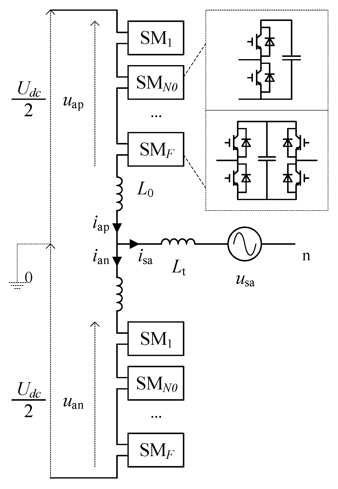
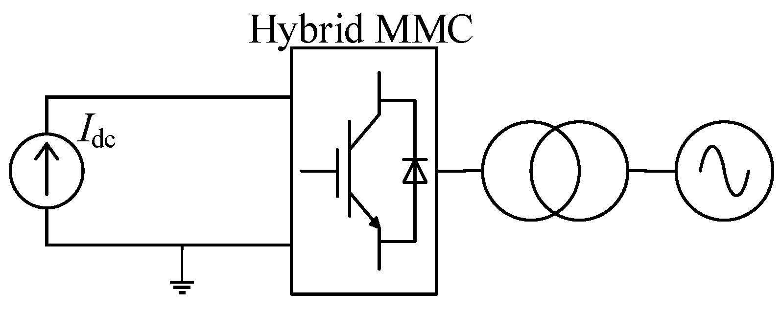
2. Hybrid MMC Utilizing Negative Voltage States of FBSMs
3. Algorithm for Solving the One-Cycle Waveforms of the Capacitor Voltages of FBSMs and HBSMs
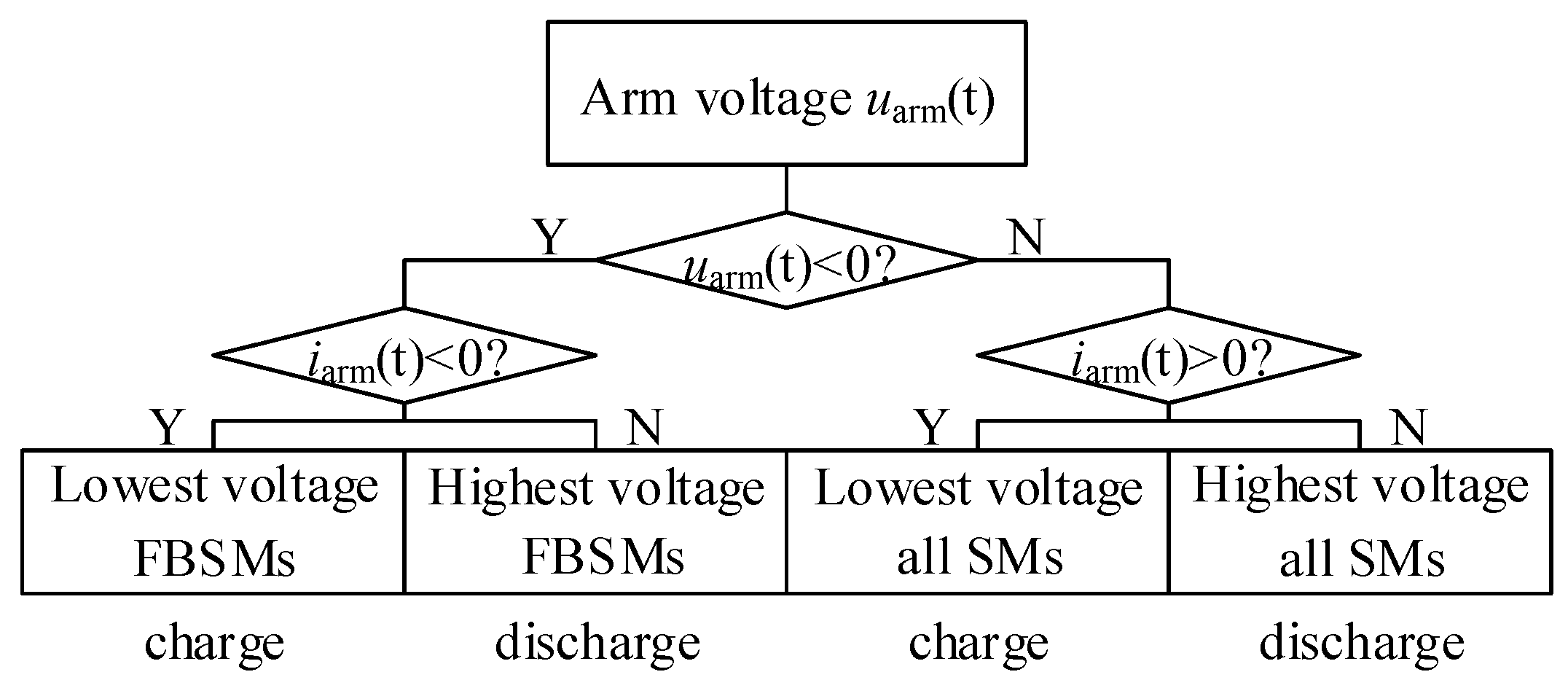
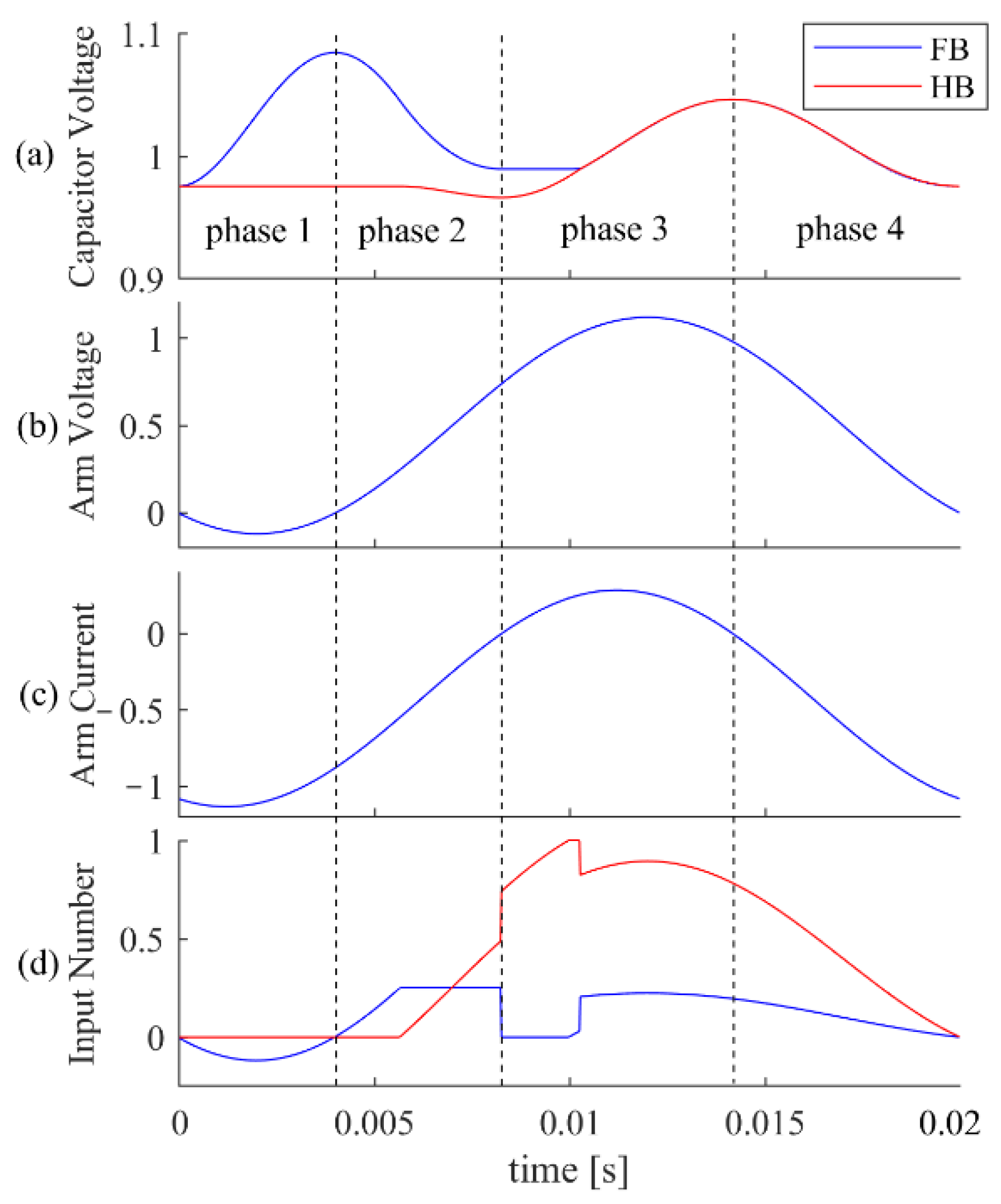
3.1. Arm Energy and Voltage Decomposition for Hybrid MMC
- (1)
- Phase 1 (charge)
- (2)
- Phase 2 (discharge)
- (3)
- Phase 3 (charge)
- (4)
- Phase 4 (discharge)
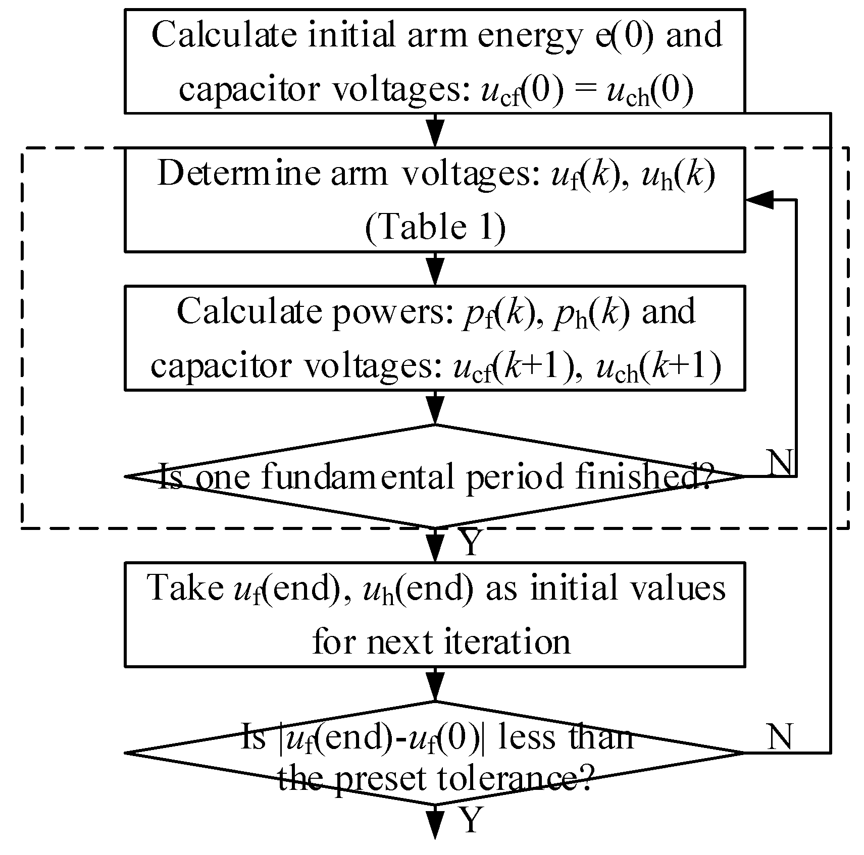
3.2. Numerical Integration and Iterative Solution Procedure
- (1)
- Initial values of the numerical calculation.
- (2)
- Numerical integration to obtain temporary one-cycle waveform.
- (3)
- Iterative solution procedure for obtaining the final one-cycle waveforms.
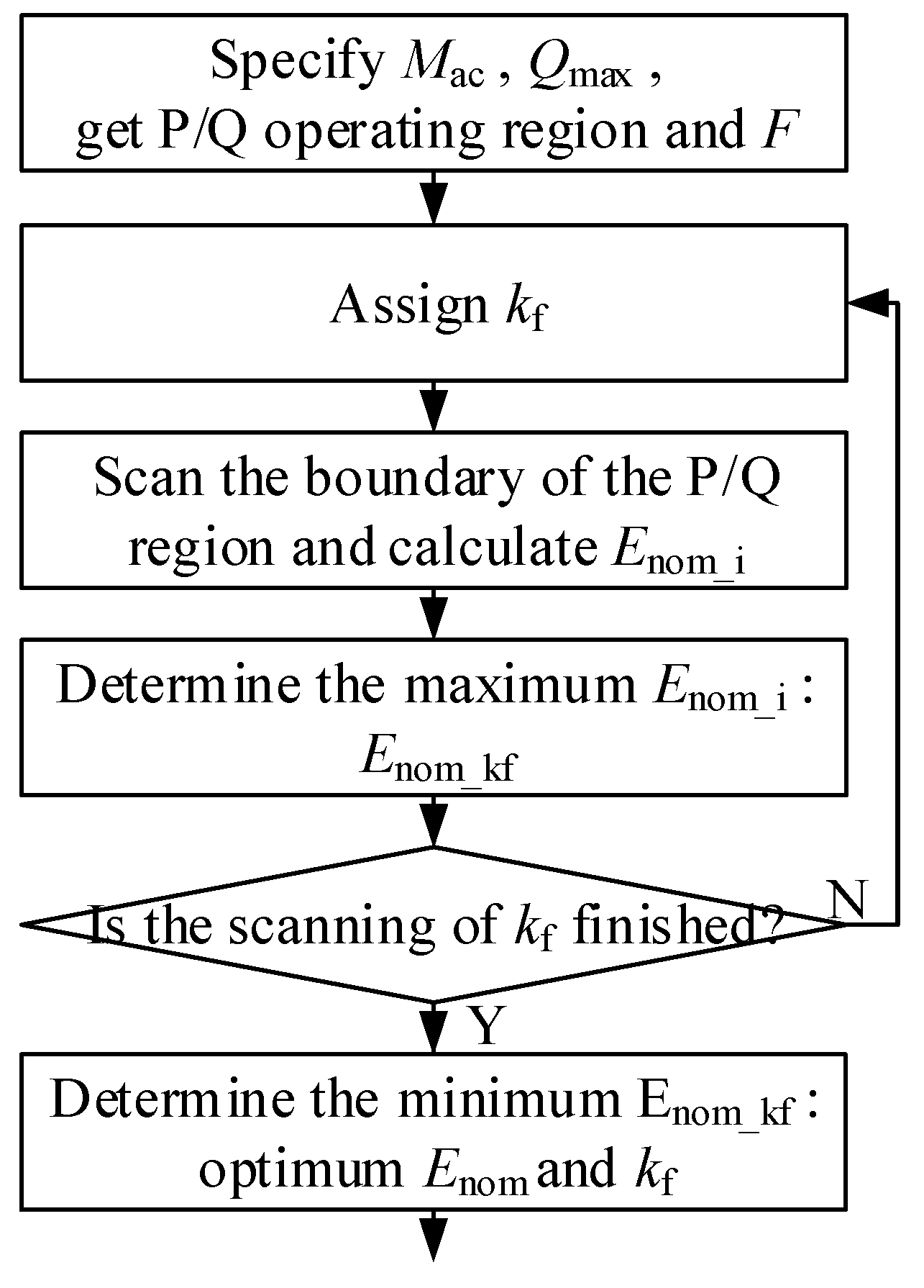
4. Method for Finding the Minimum Required Capacitances
5. Case Study and Simulation
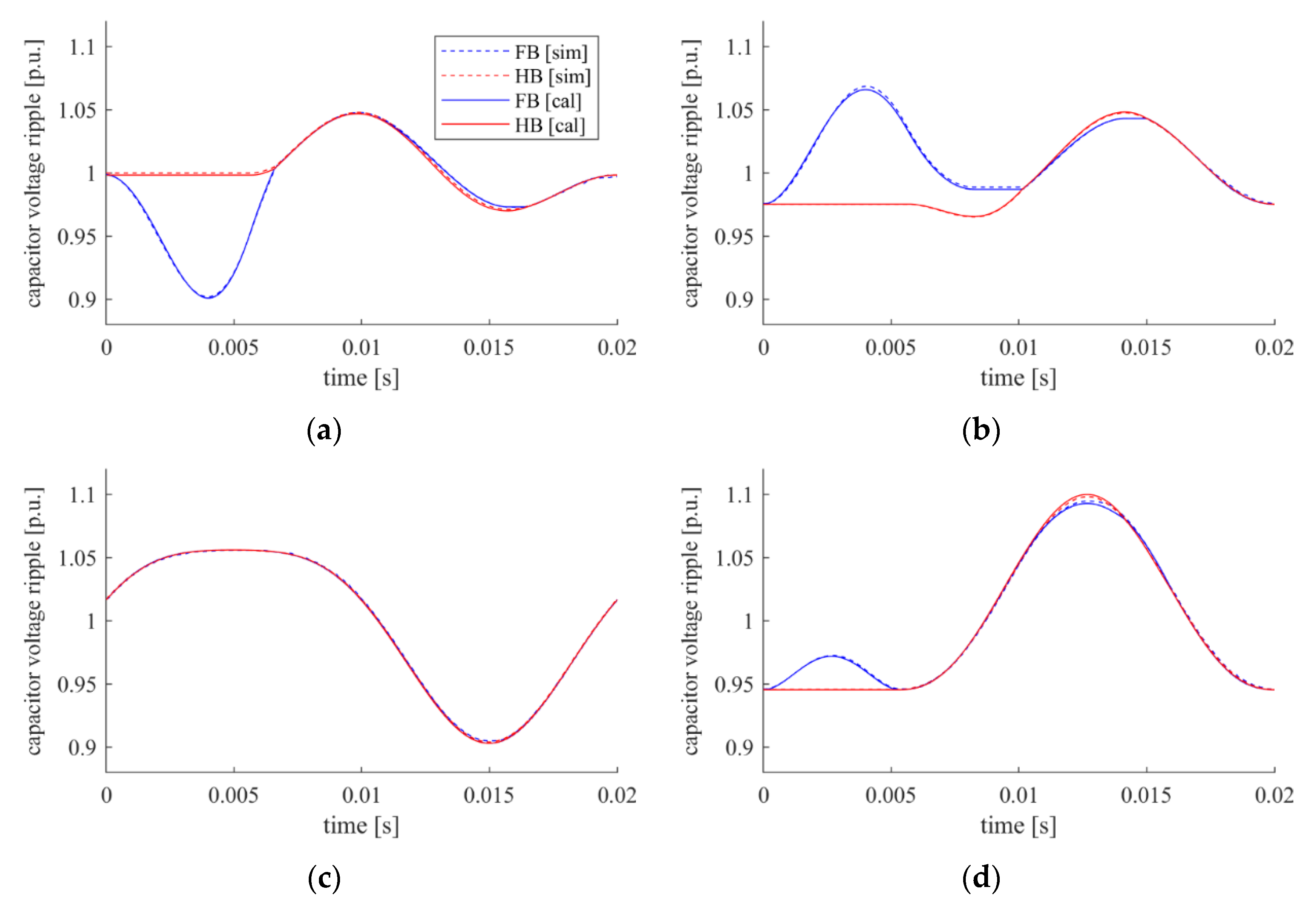
5.1. Verification of the Theoretical Calculation Algorithm under Certain Values of M0 and Qmax
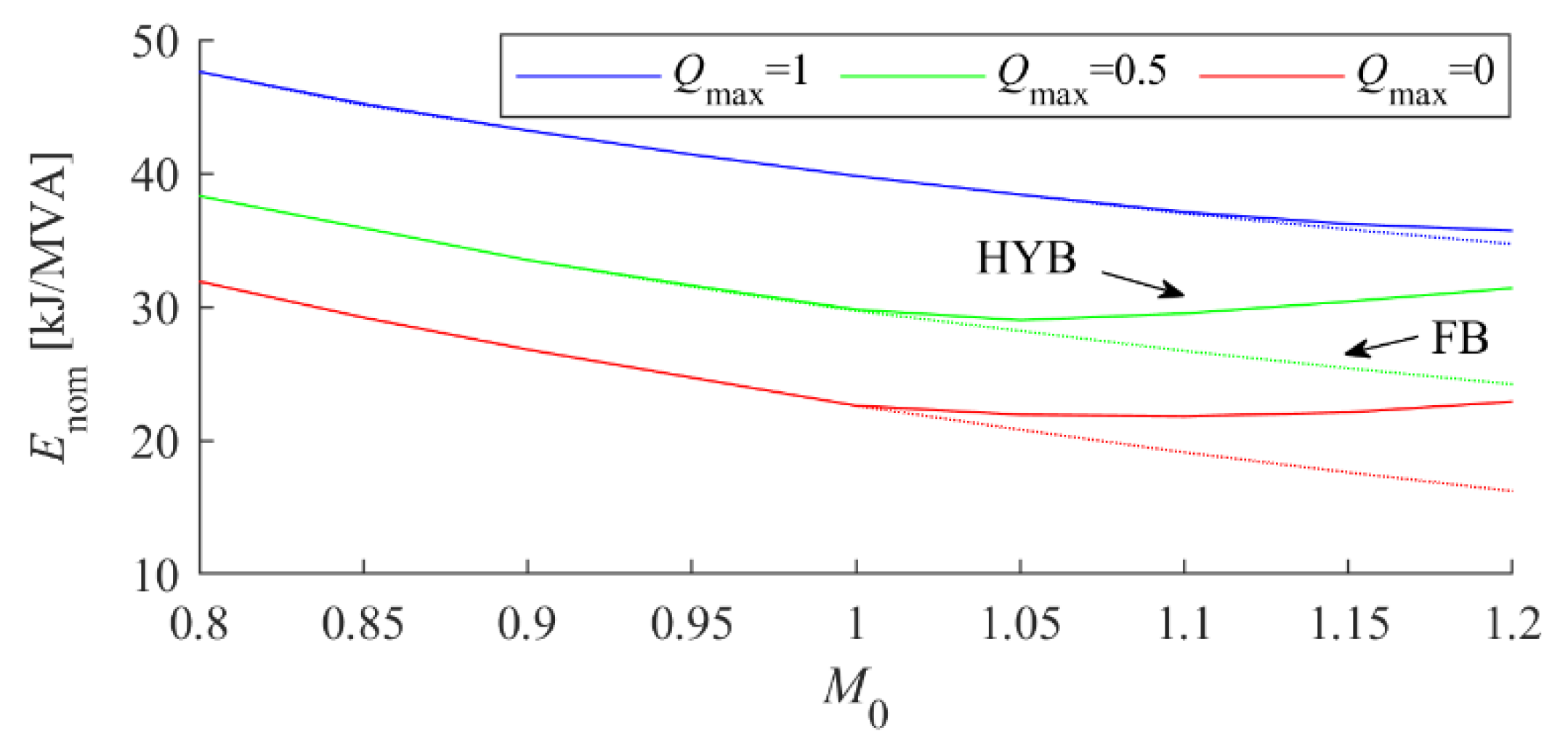
5.2. Analysis of the Impacts of the Base Modulation Index and Maximum Reactive Power on Capacitor Usage and the Number of Extra FBSMs
6. Discussion on Advantages of the Proposed Method and Conclusions
Author Contributions
Funding
Institutional Review Board Statement
Informed Consent Statement
Data Availability Statement
Conflicts of Interest
Nomenclature
| N0 | Base number of HBSM. |
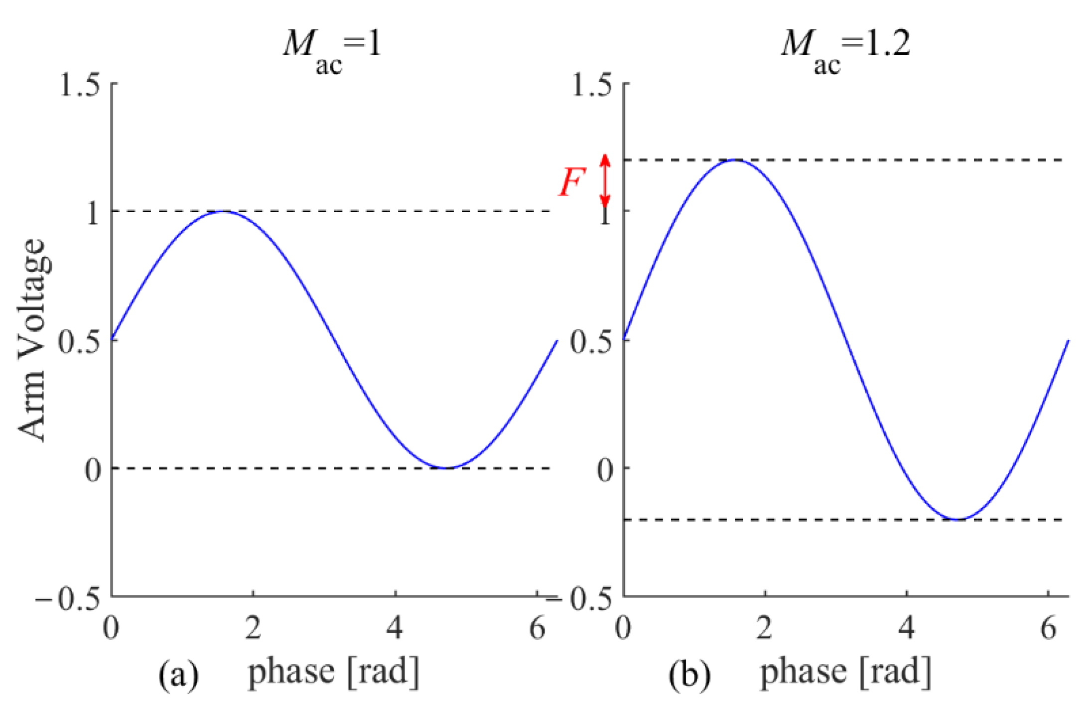
| F | Number of FBSM appended. |
| uap | Arm voltage of phase A upper arm. |
| uan | Arm voltage of phase A lower arm. |
| iap | Arm current of phase A upper arm. |
| ian | Arm current of phase A lower arm. |
| Udc | DC voltage. |
| Idc | DC current. |
| Us | AC grid RMS phase voltage. |
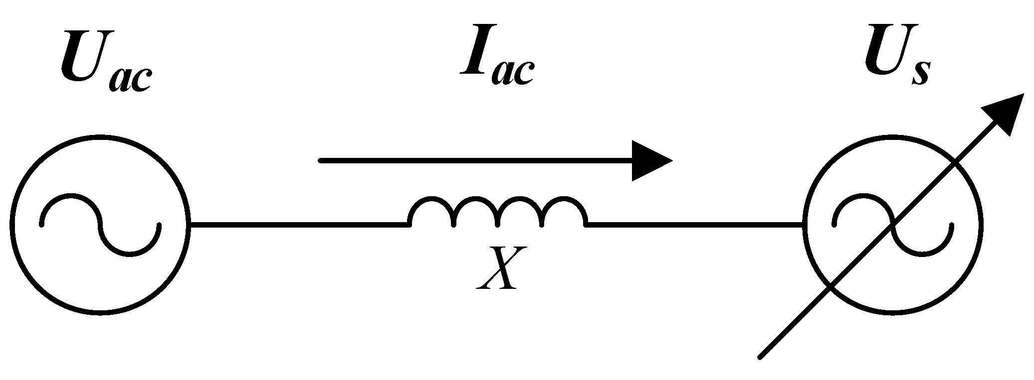
| Uac | AC port RMS phase voltage of MMC. |
| δ | AC port phase voltage phase of MMC. |
| Iac | AC RMS current of MMC. |
| φ | AC current phase of MMC. |
| X | Equivalent reactance between MMC and AC grid. |
| Mac | Modulation index. |
| M0 | Base modulation index. |
| Uc | Base capacitor voltage. |
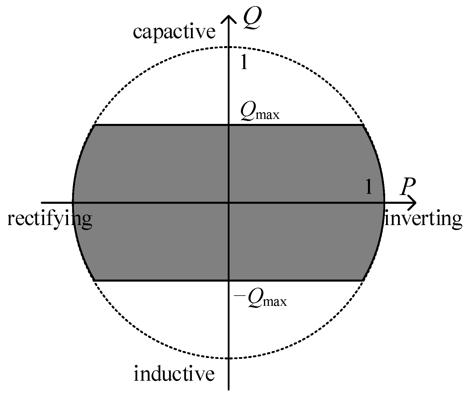
| Qmax | Maximum reactive power of MMC. |
| ucf | Capacitor voltage of FBSM. |
| uch | Capacitor voltage of HBSM. |
| Cd | Capacitance of HBSM. |
| kf | Capacitance ratio of FBSM to HBSM. |
| ef | Arm capacitor energy of FBSM. |
| eh | Arm capacitor energy of HBSM. |
| Enom | Energy storage requirement of MMC. |
| Enomf | Energy storage requirement of FBSM. |
| Enomh | Energy storage requirement of HBSM. |
| SN | Capacity of MMC. |
| uarm | Arm voltage. |
| iarm | Arm current. |
| uf | Arm voltage of FBSM. |
| uh | Arm voltage of HBSM. |
| pf | Arm power of FBSM. |
| ph | Arm power of HBSM. |
| T1 | Fundamental-frequency period. |
| εlim | Upper limit of capacitor voltage. |
| Enom_i | Energy requirement at operating point i. |
| Enom_kf | Energy requirement at capacitance ratio kf. |
| Superscript * | Per unit value. |
| Functional space | Fundamental-frequency period: [0, T1]. |
References
- Lesnicar, A.; Marquardt, R. An innovative modular multilevel converter topology suitable for a wide power range. In Proceedings of the IEEE Bologna Power Tech Conference Proceedings, Bologna, Italy, 23–26 June 2003; Volume 3, p. 6. [Google Scholar] [CrossRef]
- Hagiwara, M.; Akagi, H. Control and Experiment of Pulsewidth-Modulated Modular Multilevel Converters. IEEE Trans. Power Electron. 2009, 24, 1737–1746. [Google Scholar] [CrossRef]
- Tu, Q.; Xu, Z.; Xu, L. Reduced Switching-Frequency Modulation and Circulating Current Suppression for Modular Multilevel Converters. IEEE Trans. Power Deliv. 2011, 26, 2009–2017. [Google Scholar]
- Harnefors, L.; Antonopoulos, A.; Norrga, S.; Angquist, L.; Nee, H.-P. Dynamic Analysis of Modular Multilevel Converters. IEEE Trans. Ind. Electron. 2013, 60, 2526–2537. [Google Scholar] [CrossRef]
- Han, X.; Sima, W.; Yang, M.; Li, L.; Yuan, T.; Si, Y. Transient Characteristics under Ground and Short-Circuit Faults in a ±500 kV MMC-Based HVDC System with Hybrid DC Circuit Breakers. IEEE Trans. Power Deliv. 2018, 33, 1378–1387. [Google Scholar] [CrossRef]
- Davidson, C.; Trainer, D. Innovative concepts for hybrid multi-level converters for HVDC power transmission. In Proceedings of the 9th IET International Conference on AC and DC Power Transmission (ACDC 2010), London, UK, 19–21 October 2010; pp. 1–5. [Google Scholar]
- Picas, R.; Pou, J.; Ceballos, S.; Agelidis, V.G.; Saeedifard, M. Minimization of the capacitor voltage fluctuations of a modular multilevel converter by circulating current control. In Proceedings of the IECON 2012—38th Annual Conference on IEEE Industrial Electronics Society, Montreal, QC, Canada, 25–28 October 2012; pp. 4985–4991. [Google Scholar] [CrossRef]
- Picas, R.; Pou, J.; Ceballos, S.; Zaragoza, J.; Konstantinou, G.; Agelidis, V.G. Optimal injection of harmonics in circulating currents of modular multilevel converters for capacitor voltage ripple minimization. In Proceedings of the 2013 IEEE ECCE Asia Downunder, Melbourne, Australia, 3–6 June 2013; pp. 318–324. [Google Scholar]
- Pou, J.; Ceballos, S.; Konstantinou, G.; Agelidis, V.G.; Picas, R.; Zaragoza, J. Circulating current injection methods based on instantaneous information for the modular multilevel converter. IEEE Trans. Ind. Electron. 2015, 62, 777–788. [Google Scholar] [CrossRef] [Green Version]
- Li, X.; Song, Q.; Liu, W.; Xu, S.; Zhu, Z.; Li, X. Performance Analysis and Optimization of Circulating Current Control for Modular Multilevel Converter. IEEE Trans. Ind. Electron. 2016, 63, 716–727. [Google Scholar] [CrossRef]
- Ilves, K.; Norrga, S.; Nee, H.-P. On energy variations in modular multilevel converters with full-bridge submodules for Ac-Dc and Ac-Ac applications. In Proceedings of the 2013 15th European Conference on Power Electronics and Applications (EPE), Lille, France, 2–6 September 2013; pp. 1–10. [Google Scholar]
- Ilves, K.; Norrga, S.; Harnefors, L.; Nee, H.-P. On Energy Storage Requirements in Modular Multilevel Converters. IEEE Trans. Power Electron. 2014, 29, 77–88. [Google Scholar] [CrossRef]
- Song, Q.; Yang, W.; Zhao, B.; Xu, S.; Rao, H.; Zhu, Z. Energy Storage Requirement Reduction Using Negative-Voltage States of a Full-Bridge Modular Multilevel Converter. IEEE Trans. Power Electron. 2019, 34, 5243–5255. [Google Scholar] [CrossRef]
- Judge, P.D.; Chaffey, G.; Merlin, M.M.C.; Clemow, P.R.; Green, T.C. Dimensioning and Modulation Index Selection for the Hybrid Modular Multilevel Converter. IEEE Trans. Power Electron. 2017, 33, 3837–3851. [Google Scholar] [CrossRef] [Green Version]
- Dong, P.; Lyu, J.; Cai, X. Optimized Design and Control for Hybrid MMC With Reduced Capacitance Requirements. IEEE Access 2018, 6, 51069–51083. [Google Scholar] [CrossRef]
- Zhao, C.; Lei, M.; Hu, Y.; Li, Z.; Gao, F.; Wang, P.; Li, Y. Energy Storage Requirement Optimization of Hybrid Modular Multilevel Converter with Circulating Current Injection. IEEE Trans. Ind. Electron. 2019, 66, 6637–6648. [Google Scholar] [CrossRef]
- Lin, L.; Lin, Y.; Xu, C.; Chen, Y. Comprehensive Analysis of Capacitor Voltage Fluctuation and Capacitance Design for Submodules in Hybrid Modular Multilevel Converter with Boosted Modulation Index. IEEE J. Emerg. Sel. Top. Power Electron. 2018, 7, 2369–2383. [Google Scholar] [CrossRef]
- Hu, J.; Xiang, M.; Lin, L.; Lu, M.; Zhu, J.; He, Z. Improved Design and Control of FBSM MMC with Boosted AC Voltage and Reduced DC Capacitance. IEEE Trans. Ind. Electron. 2018, 65, 1919–1930. [Google Scholar] [CrossRef]
- Zeng, R.; Xu, L.; Yao, L.; Williams, B.W. Design and Operation of a Hybrid Modular Multilevel Converter. IEEE Trans. Power Electron. 2015, 30, 1137–1146. [Google Scholar] [CrossRef] [Green Version]
- Lu, M.; Hu, J.; Zeng, R.; Li, W.; Lin, L. Imbalance Mechanism and Balanced Control of Capacitor Voltage for a Hybrid Modular Multilevel Converter. IEEE Trans. Power Electron. 2018, 33, 5686–5696. [Google Scholar] [CrossRef]
- Lu, M.; Hu, J.; Zeng, R.; He, Z. Fundamental-Frequency Reactive Circulating Current Injection for Capacitor Voltage Balancing in Hybrid-MMC HVDC Systems During Riding Through PTG Faults. IEEE Trans. Power Deliv. 2018, 33, 1348–1357. [Google Scholar] [CrossRef]
- Lee, J.-H.; Jung, J.-J.; Sul, S.-K. Balancing of Submodule Capacitor Voltage of Hybrid Modular Multilevel Converter under DC-Bus Voltage Variation of HVDC System. IEEE Trans. Power Electron. 2019, 34, 10458–10470. [Google Scholar] [CrossRef]
- Sidorov, D.; Panasetsky, D.; Tomin, N.; Karamov, D.; Zhukov, A.; Muftahov, I.; Dreglea, A.; Liu, F.; Li, Y. Toward zero-emission hybrid AC/DC power systems with renewable energy sources and storages: A case study from lake Baikal region. Energies 2020, 13, 1226. [Google Scholar] [CrossRef] [Green Version]


| Only FBSM input: | Maximum HBSM input: | Maximum FBSM input. | |
| Equally input: | Equally input. | ||
| Maximum FBSM input: | Maximum HBSM input. | ||
| Parameters | Values |
|---|---|
| Rated capacity | 1250 MVA |
| Rated DC voltage | 400 kV |
| Rated AC voltage (line) | 294 kV (M0 = 1.2) |
| Maximum reactive power | 1 p.u. |
| Rated capacitor DC voltage | 2 kV |
| Equivalent AC reactance | 44 mH (0.25 p.u.) |
| HBSM quantity | 200 (1 p.u.) |
| FBSM quantity | 50 (0.25 p.u.) |
| Capacitor usage | 35.7 kJ/MVA |
| Capacitance ratio | 1.3 |
| Capacitance of FB/HBSM | 18.2/14 mF |
Publisher’s Note: MDPI stays neutral with regard to jurisdictional claims in published maps and institutional affiliations. |
© 2022 by the authors. Licensee MDPI, Basel, Switzerland. This article is an open access article distributed under the terms and conditions of the Creative Commons Attribution (CC BY) license (https://creativecommons.org/licenses/by/4.0/).
Share and Cite
Wang, K.; Song, Q.; Xu, S. Analysis and Design of the Energy Storage Requirement of Hybrid Modular Multilevel Converters Using Numerical Integration and Iterative Solution. Energies 2022, 15, 1225. https://doi.org/10.3390/en15031225
Wang K, Song Q, Xu S. Analysis and Design of the Energy Storage Requirement of Hybrid Modular Multilevel Converters Using Numerical Integration and Iterative Solution. Energies. 2022; 15(3):1225. https://doi.org/10.3390/en15031225
Chicago/Turabian StyleWang, Kailun, Qiang Song, and Shukai Xu. 2022. "Analysis and Design of the Energy Storage Requirement of Hybrid Modular Multilevel Converters Using Numerical Integration and Iterative Solution" Energies 15, no. 3: 1225. https://doi.org/10.3390/en15031225
APA StyleWang, K., Song, Q., & Xu, S. (2022). Analysis and Design of the Energy Storage Requirement of Hybrid Modular Multilevel Converters Using Numerical Integration and Iterative Solution. Energies, 15(3), 1225. https://doi.org/10.3390/en15031225