Abstract
This paper presents the final development of an expert system utilizing a measurement of cable screen earthing transient current. The developed system allows for identification and location of earth fault in underground cable and mixed lines (underground cable and overhead line) and monitoring of an earthing system and cable screen connections. The unique feature of the developed earth fault locating system is the possibility of identification of line type and branch of the MV underground cable or mixed feeder under earth fault conditions. As a result, the time to remove failure can be greatly reduced and the number of earth fault indicators installed in the distribution network can also be reduced. Unfortunately, in order to operate properly, the previously developed system requires a fundamental—50 Hz component of the measured zero-sequence cable core current and cable screen earthing current; therefore, short transient earth faults without steady-state earth fault currents cannot be localized and categorized even though the transient earth faults have a negative impact on the power system. According to measurements performed by the authors, transient earth faults are relatively frequent, which causes stress to insulation. The number of transient earth faults may be reduced by ensuring proper maintenance of the distribution system. Unfortunately, because of the very large area of the distribution feeder, often in the range of tens of kilometers or even around a hundred kilometers, and many potential causes of earth faults, it is very difficult to localize the transient earth fault and determine the cause of the earth fault. Herein, we present the possible causes of transient earth faults and methods developed for the analysis of transient earth faults. Moreover, the novel algorithm for transient earth fault detection and location is proposed. The proposed algorithm has a self-learning capability and can identify branches of the distribution feeder under transient earth fault conditions. The effectiveness of the proposed algorithm is confirmed thanks to the performed network experiment.
1. Introduction
Earth faults are one of the most common fault types in the distribution system networks. It is estimated that earth faults stand for 70–80% of faults [,,,,]. The occurrence of earth faults is connected with many negative phenomena—the risk of electrocution, transient overvoltages or thermal damages due to current flow []. Earth faults can be categorized as permanent and transient earth faults. Transient earth faults can be divided into subcategories—intermittent and incipient. In the case of intermittent earth faults, an earth fault is initiated and extinguished cyclically. Moments of earth fault initiation and termination are connected with transients overvoltages, which lead to a reduction in insulation strength in the range of 10–20% []. Incipient earth faults are very short earth faults, which last for very short time in range of milliseconds.
Despite the big efforts on reducing the number of earth faults in distribution system networks, e.g., cutting trees in the vicinity of overhead line, adding squirrel guard or bird spikes, and mechanical barriers to prevent mechanical damages [], it is not possible to completely eliminate earth faults in distribution systems. It is therefore mandatory to develop methods for the detection and location of earth faults and transient earth faults. The literature presents a large number of publications about earth fault detection. The work in [] proposes the utilization of multi-resolution wavelet analysis and Mallat algorithm for transient earth fault detection. According to simulation results, the proposed method is an effective solution for the intermittent earth fault (IEF) detection, particularly in compensated networks. In [], using the zero-sequence voltage and a sum current of phase currents, the intermittent earth fault is identified if the amplitude of the voltage and current exceed corresponding set values and the phase difference is within the set values. In [], the authors present two algorithms based on fuzzy logic. According to the authors, they are also effective when the classic quantitative methods are not successful. In [,], the authors propose using the patented Cumulative Phasor Summing and multifrequency admittance criterion to detect intermittent and re-striking earth faults in a compensated network. The performance of the novel function has been validated using hundreds of disturbance recordings from compensated and unearthed networks. The authors indicate that the method is universal—it detects all types of earth faults. One must, however, underline that state-of-the-art protection relays detect transient earth fault only if many transient earth faults are appearing in a short time window determined by the time setting of the earth fault protection relay—typically in the range of tens of seconds to a few seconds. Transient earth faults are discarded and not classified. Another problem connected with transient earth faults is the very limited literature presenting methods of transient earth faults location. Incipient earth faults in underground cable lines may be located using two ends measurements [,], however, the method utilizes two sensors at both cable ends what significantly increases the costs of installation. Moreover, the installation of sensors in depths of the network is often difficult since new types of MV switchgear often require de-energization before the sensor is installed. De-energization is required because of the safety reasons and in case of gas insulated switchgears, the insulation gas SF6 has to be extracted before the installation of the sensors because of high global warning potential []. Moreover, the method is limited to the single segment underground cable line, which is rarely found in the real distribution system network.
The method proposed in this paper is based on measurement of cable screen earthing current— and zero sequence cable core current . The method is a development of methods presented in [,], which utilize information about the ratio of fundamental (50 Hz) components of and , as well as information about phase shift between and . The method is applicable for underground cable feeders, which consist of many multi-point earthed cable sections. The new proposed method is based on the analysis of the transient components of the very first moment of earth fault currents flow. The principle of operation of the transient location method is based on observation of currents waveforms in a transient state and on comparison of local extremes of measured currents. Both magnitudes of peaks and moments of occurrence are compared in order to identify the line type and segment of the distribution feeder under phase-to-earth fault conditions. The proposed method is universal for all types of transient fault and utilizes single-point measurement. The developed method can be implemented in protection relays to detect repeating transient earth faults and has the unique ability to determine line type affected by transient earth fault what allows to adapt time setting to line type affected by the earth fault. The proposed method can also be used in expert systems to identify and locate problematic fragments of the distribution system network.
This paper is organized as follows. First, we present the theoretical background followed by the presentation of results of preliminary measurements in MV network, then the algorithm developed for detection and location of transient earth faults. The penultimate section presents the results of the MV network experiments. The last section presents the summary and outlines the further research.
2. Transient Earth Faults
Transient earth faults are characterized by the dynamic and short rise of current amplitude and distortion of the voltage waveform. The transient earth faults may last just a few ms and stop or be reignited after a short time. Figure 1 presents an exemplary sequence of an intermittent fault—10 earth faults are observed one after another, which were initiated and extinguished in a very short time in most cases before steady state earth fault current can be observed. In two cases marked with a blue ellipse, one can notice the steady state earth fault current. One can notice high peak currents during the initiation of the earth fault up to 250 Amps. After each earth fault, the zero-sequence voltage is decreasing and is coming back to nominal values. The slow process of voltage recovery can be explained by the neutral point treatment method—the Petersen coil (capacitive current of the network 80 A, detuning factor 1.15 and shunt resistor with nominal current 20 A). The short-lived IEF are typically not analyzed or categorized because of lack of proper methods, whereas very frequently reigniting transient earth faults are detected by conventional earth fault protection methods—using the moving average tool when the time between the occurrence of IEF is very short and the IEF occur for a prolonged time []. Transient earth faults are dangerous as the voltage reaches a high peak—in the range of 2.5 to 4 times of nominal voltage depending on neutral point treatment []. After the earth fault is terminated, the process of voltage recovery is started. Voltage in the phase under phase to earth fault is rising and voltage in 2 other—‘healthy’ phases is reduced []. In the case of resistor earthed networks, the voltage recovery is practically instantaneous, whereas, in the compensated network, the voltage recovery may last for a few tens of seconds to tens of seconds. Shunt resistor effectively reduces the time of voltage recovery and the voltage recovery lasts a few tens of seconds to a few seconds [,]. The amplitude of earth fault current and voltage— and —strongly depends on the parameters of the network—capacitive current, neutral point treatment, fault impedance and moment of earth fault occurrence [].
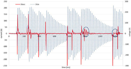
Figure 1.
An example of intermittent earth fault; phase values measured at the secondary side of protection class instrument transformers (150/5 A and / and added in order to obtain the zero sequence values (according to symmetrical components theory).
Transient earth faults may occur both in underground cable and overhead lines. Transient earth faults in overhead lines can be divided into the following groups:
- earth faults caused by vegetation near the overhead line []; reduction of earth fault number is achieved via vegetation management and utilization of insulated overhead lines [,],
- earth faults caused by animals and birds; reduction of earth fault number is achieved thanks to insulation layers in critical locations and physical barriers [,,,],
- earth fault caused by equipment deterioration or damage; earth fault number is reduced thanks to proper maintenance [],
- earth faults caused by human activities, e.g., damage during construction or agricultural works—earth fault number reduced by proper design,
- atmospheric conditions, i.e., icing, wind—earth fault number reduced by proper design.
Examples of transient earth faults that may occur along the underground cable lines:
- moisture on insulators on the area of substation [],
- contamination of insulators at the point of line transition—underground cable to overhead line, and
- in rare cases the incipient earth fault may occur along the underground cable (see below).
Transient earth faults in underground cable lines are presented in []. Transient earth faults can occur in different cable types including the most common XLPE insulated cables. The transient earth fault is started after water penetrates cable insulation. At some point, high-power transient earth fault current starts flowing for approximately to 5 cycles. The current flow generates heat, which evaporates the water and melts the insulation what allows for temporal recovery of insulation. However, after some time the earth fault occurs again []. In order to identify the source of transient earth fault, one has to analyze the trend of occurrence knowing that transient earth faults in underground cable lines are characterized by the rise of occurrence (time difference between the consecutive incipient earth faults). It is estimated that approximately 10–15% of cable lines in the USA are preceded by intermittent earth faults []. The authors of [] state that the majority (80%) of transient earth faults in cable line is connected with cable joints or splices because of manual assembly in difficult environmental conditions. It is also possible to detect IEF using partial discharge (PD) measurement. It is estimated that the time between the very first PD and permanent earth fault (with 50% probability) is 12 days []. Detailed analysis of transient earth fault in Portuguese power system is presented in []. According to the analysis, it is possible to detect transient earth faults before the permanent earth fault, however, further research, e.g., regarding time before failure is needed. According to operational experience, it is possible to reconnect the damaged cable line after operation of earth fault protection relay and the line is able to operate properly for some time []. If the reigniting transient earth faults are not recognized as the prefailure condition of the power cable and the cable is reconnected to the power network the failure of the cable is imminent. Early identification of transient earth faults is important as it allows for
- reconfiguration of the network in order to avoid or minimize interruption of power supply;
- better planning of the purchasing process, i.e., replacement parts on time;
- early replacement of the faulty components of the power line; and
- reduction of the time of failure removal time thanks to pre-failure analysis, e.g., location of failure is determined.
No earth fault location or classification method is perfect, e.g., the author of [] states that developed wavelet classification technique operates properly in 80 to 95% of cases. The proposed method of transient earth fault location can be utilized in parallel with different tools, i.e., waveform analysis tools or distance protection, which requires the steady state earth values to locate the earth fault []. The basic ability of waveform analysis is the classification of the fault type, i.e., 3 or 1 phase []. It is also possible to identify the cause of earth fault—animals or vegetation. Identification of the cause of IEF is based on analysis of characteristic parameters of electric arc and time of fault occurrence, waveform, damping, frequency-domain energy of fault voltage and arc voltage []. The topic is being analyzed up to date and new methods of determining the causes of earth faults are being developed, e.g., measurement of the rise time and decay time of current []. Based on the operational experience from the USA, one can conclude that it is possible to identify an element of cable line under phase to earth fault conditions, i.e., cable line, cable joint or cable head based on waveform analysis []. One has to, however, underline that American networks and European networks differ significantly—4-wire systems in the USA and 3-wire systems in the EU connected with different neutral point treatment methods. It is therefore not possible to directly utilize rules developed in the USA for European distribution networks.
3. Observations in Distribution System Network
This section presents the chosen transient signals recorded during measurements in a few 110/15 kV substations. Figure 2 presents the typical configuration of the section of 110/15 substation in Poland, which consist of an HV/MV transformer, earthing transformer and power lines. The goal of the section is to present methods of conventional analysis and outline the principle of operation as well as the benefits of the proposed system for transient earth fault location and detection.
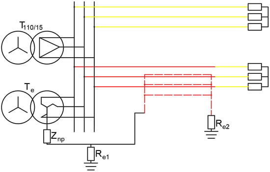
Figure 2.
Scheme of 1 section of typical 110 kV/15 kV substation in Poland; with exemplary overhead line (yellow) and underground cable line (red).
The inductive coupling is a source of cable screen current flow under earth fault conditions outside of the cable line—overhead part of the feeder, whereas in the case of earth fault in underground cable line the major source of cable screen current is a galvanic connection between cable core and cable screen or earthing system as all metallic elements are interconnected in order to equalize the potential of metallic elements. If the current is induced in cable screens one can observe phase shift between and , whereas in the case of ideal galvanic connection currents are in phase (or opposite phase depending on the polarization of current sensors). In real cases, the current resulting from the galvanic connection is superimposed with residual inductive current, which is a result of a difference between and returning through cable screen to point of measurements. As a result, the is slightly shifted in relation to . Detailed information connected with the impedance of cable screen and cores may be found in []. The presented theory is used to determine if the underground cable or overhead segment is under earth fault conditions.
During measurements, a sequence of earth faults occurred in a short time. The situation is rather unexpected as previous days did not reveal earth faults in the line. Preliminarily, it was concluded that the reason for earth faults was connected with sudden degradation of insulation properties or atmospheric conditions. Verification of ambient conditions allowed us to conclude that the storm occurred in the areas of the feeder. No earth fault was recorded in the following days, allowing us to conclude that the most probable cause was a strong wind which pushed tree branches close to the overhead line. It was recommended to cut tree branches along the feeder. Unfortunately, it is not clear, which line of the distribution feeder is affected. Theoretically in order to locate the segment (branch) of the feeder under phase to earth fault conditions, one can use different techniques, e.g., use geographical maps and verify the places where trees grow nearby the power lines []. It is however very time-consuming process, which in many cases is not able to determine suspected branches, e.g., to many locations. The only practical solution to limit the search area is the installation of the earth fault current indicator in almost every branch of the feeder, i.e., 5 or even 10 earth fault current indicators. One has to however underline that one need to perform complex analysis in order to specify the location of the fault current indicators and perform additional maintenance activities on the installed equipment []. Alternatively, in ideal case utilization of the developed algorithm with just one additional current sensor in 110/15 substation at the beginning of the feeder.
In order to distinguish the branch of feeder under earth fault conditions, one needs to know the phase shift between and under transient earth fault conditions. Unfortunately, the moment of earth fault initiation is very difficult to characterize using conventional analytical techniques and simulation tools. Literature research did not allow to find proper tools for detailed recreation of the transient state of current in cable cores and cable screens. Moreover, if the proper calculation method is developed, one needs to precisely specify cable parameters to get an accurate representation of the transient state, which is practically impossible. However, one needs to underline that state-of-the-art software may be used to analyze transient overvoltages in underground cable lines []. It is therefore concluded that for the purpose of earth fault locating, one can use transient references—fingerprints (often used for diagnostic purposes [,]), which are obtained during other transient earth faults. The fingerprints are obtained based on analysis of the phase shift and ratio of and steady-state currents (marked with a blue ellipse in Figure 1) which often follows the transient state.
The obtained fingerprints allow to determine the segment of the distribution feeder (branch), in which the transient earth fault occurred. Categorization is based on the phase shift of transient peaks in and currents. As can be seen in the case of earth fault along the underground cable line Figure 3 the local extremes of both currents occur practically at the same time. In order to verify the hypothesis and make sure that the recorded results are not an accident, the network experiment is performed, what is presented in further sections.
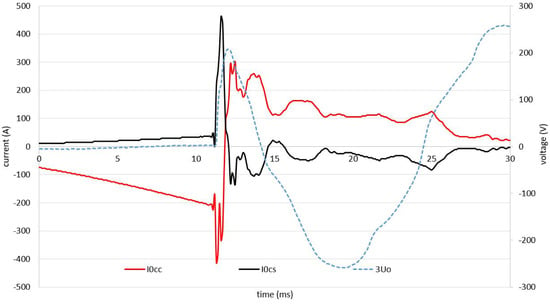
Figure 3.
Cable screen and core currents during initiation of earth fault.
It is also noted that both the incipient earth faults characterized by relatively smooth shape, see Figure 4, and intermittent earth faults characterized by many extremes are observed in the network, see Figure 5.
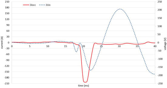
Figure 4.
Exemplary incipient earth fault.
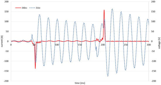
Figure 5.
Exemplary intermittent earth fault.
4. Algorithm
The algorithm for detection and pre-locating transient earth faults (without steady-state component) (Figure 6) runs in parallel with an algorithm for detection and location of steady-state earth faults, which is presented in previous publications [,]. The algorithm, which analyzes the steady-state component of the earth fault allows determining the segment of the distribution feeder under stable phase to earth fault conditions and to obtain the fingerprint (phase shift between local extremes during the very first moment of earth fault) of the earth fault transient state connected with the particular segment of the distribution feeder. The obtained fingerprints allow to determine the segment of the distribution feeder under very short transient earth fault conditions, which cannot be localized by the conventional system. It is also possible to manually connect the transient fingerprint with the segment of the feeder after the earth fault location is known.
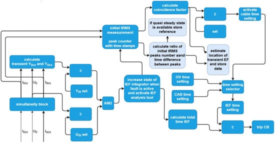
Figure 6.
Algorithm for detection and pre-locating of transient earth fault.
Detection of the transient earth faults is achieved via monitoring of the transient admittance or . Utilization of admittance eliminates the risk of unwanted operation of protection relay as in some cases zero-sequence current can be observed under different disturbance conditions, e.g., transformer energizing []. Additionally, to reduce the risk of unwanted earth fault protection, one can utilize another criterion for earth fault detection—>, which is typically set in the range of 10 V (at the secondary side of open delta voltage transformers).
In order to make sure that the CB trips only when a transient earth fault is persistent and active, the timer is used to count the duration of the earth fault. When the transient earth fault is active, the timer increases in value, and when the transient earth fault is inactive, the timer holds. When the transient earth fault is inactive for a prolonged period of time, the timer is reset.
Because IEFs have a negative impact on insulation, shorter time settings are used to trip the circuit breaker (CB). Two-time settings are used—short IEF time setting for IEF in underground cable lines (<ca. 0.1 s) and longer IEF time setting for earth faults in overhead line since the reason of earth fault may disappear. The proper time setting is activated based on the analysis of waveforms—the analysis of phase shift between local extremes (peaks) in transient and currents. The capability of identification of line type under transient phase to earth fault conditions in MV networks is a unique feature of the proposed algorithm. When the IEF timer reaches the time setting the signal to open CB is sent.
The estimation of the branch of the feeder under phase to earth fault conditions is made after the circuit breaker trips so the speed of operation is not as important and more advanced processing methods can be utilized. The estimation of the earth fault location is based on the comparison of the recorded and waveforms with the reference values. The reference transient values are connected with segments of the distribution feeders—branches, and are obtained based on analysis of the steady-state components of the and , which are the ratio and phase shift between and or manually after the waveforms are connected with a particular branch of the feeder, e.g., after earth fault removal. Every steady-state earth fault is preceded by the transient state, which also has characteristic features connected with the electrical parameters of the underground cable branches in particular one can mention the time difference between local extremes recorded in and .
In practical applications however, the developed algorithm cannot determine branch if the parameters of branches are very similar, i.e., 2 branches made of 150/25 underground cables of length 2.4 and 2.5 km because the inductive coupling of both branches is almost the same and the resulting difference of phase shift between calculations is negligible. Therefore the developed solution is able to operate properly in parts of the network where the difference of electrical parameters of branches is significant. One has to underline that it is possible to increase the difference of electrical parameters by applying different bonding methods of underground cable branches, e.g., single point bonding, cross bonding or utilize alternative cable screen bonding methods: series connection or 2 cable screens short circuited and unearthed or bonded in the middle (Figure 7) [,]. The modification of cable screen bonding methods requires however detailed analysis in the context of earth fault current flow and impact on the expected touch voltages under phase to earth fault conditions [,]. It is also noted that cable screen bonding method may have impact on zero sequence current. Another possibility of increasing the difference between different branches electrical parameters is to use different cable construction—utilize single core cables and three core cables in different branches []. Another problem connected with the developed transient algorithm is the difficulty of specifying settings which characterize different branches. As can be seen, each of the presented methods has both serious limitations and advantages, however the combination of different locating techniques and approaches helps to narrow down the search area.
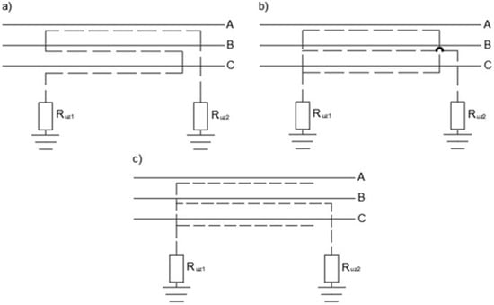
Figure 7.
Alternative cable screen bonding methods. (a) series connection of cable screens, (b) 2 unearthed and short-circuited cable screens, (c) 2 unearthed cable screens.
Despite the determination of the segment of the feeder under phase to earth fault conditions, the system analyzes the shape of transient earth faults in order to determine if the transient earth fault occur in cable line. According to the literature (American), the transient earth faults in cable line are characterized by smooth shape, which can be approximated by sine function, whereas the shape of intermittent earth fault is difficult to approximate as it consists of many random peaks. The shape can be recognized by the human or by computer tools, e.g., wavelet analysis or other simpler processing tools etc., it is possible to subtract the measured waveform from the . The reference value is artificially created after measuring the pulse max amplitude and duration of the measured signal. The exemplary is presented in (Figure 8). If the difference between the measured signal and reference is small, the incipient fault along the cable line is suspected. The reference values are changing when the fault is progressing. Initially, the failure starts with high-amplitude current, and over time the amplitude is decreasing.
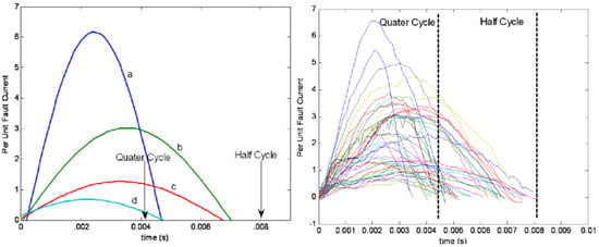
Figure 8.
Left—; right— under incipient earth fault conditions [].
The proposed algorithm has self-learning capabilities and can be implemented in different distribution feeders. The bigger the difference of branch electrical parameters, the bigger the time difference between local extremes of both currents is observed. In order to apply the method in feeders with similar branches (inconclusive time difference), one can perform modification of cable screen connection and apply alternative cable screen connections.
5. Verification of the Proposed Algorithm
The measurement results are presented in this section. Observations in the distribution system network allowed us to analyze the transient earth faults and create a set of rules, which could be used in the system for detecting and locating of transient earth faults. Unfortunately, many measurements were taken at the secondary side of protection class current transformers, which are characterized by relatively big measurement error and therefore network experiment with precise meters—Rogowski coils is needed []. Figure 9 presents the connection scheme during the experiment. Rogowski coils, which are very accurate both in-phase and magnitude measurements are used. The line is 370 m 3xNA2XS(F)2Y 150 mm/25 mm underground cable and overhead section. The resistance of cable screen earthing system is 6 at the load side. The underground cable is buried 80 cm below and is laid in a trefoil formation. The poles of overhead line are 13.5 m high. The wires are plastic-covered overhead conductors without metal sheaths—so called PAS system (Finnish language—Päällystetty Avojohto Suurjännitteelle). The wires are placed in flat formation and the spacing between wires is 0.6 m. The span length is approximately 85 m. The capacitive current of the network during the experiment was in range of 75–85 A. The change of the capacitive current is a result of disconnection of one distribution feeder in the middle of network experiment. The neutral point of the network was earthed via Petersen coil with an active current forcing resistor. The detuning factor of the coil is 1.15–1.2 and the nominal current of the resistor is 20 A.
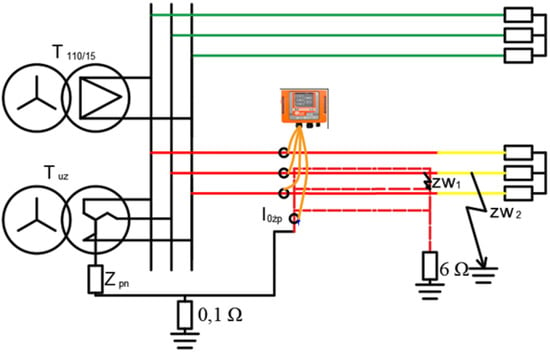
Figure 9.
Scheme of the measuring system.
The experiment is based on making a connection between the underground cable core and cable screens at the end of the underground cable or between the overhead line and earthing system of the overhead line pole. In order to make sure the measurements are repeatable, 11 earth faults are made. Figure 10 presents equipment used during the network experiment—remote-controlled circuit breaker, which connects one of the phases with earthing system and basket lift used to make proper connection. Figure 11 presents waveforms of and under phase-to-earth fault in underground cable line, whereas Figure 12 presents the currents in case of earth faults in overhead section. Based on analysis of the figures, one can conclude that the ratio of true RMS (tRMS) in cable core and tRMS—refereed further as return factor () in cable screen earthing system could be used for locating purposes.
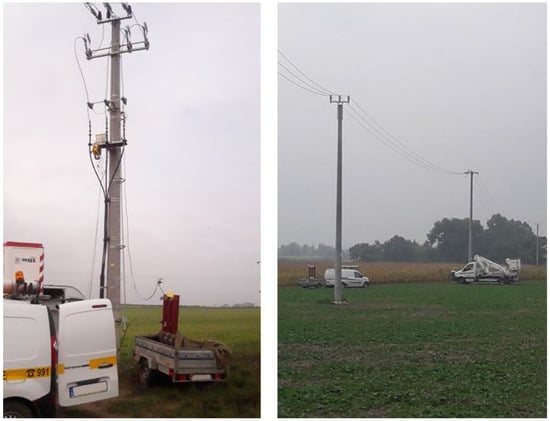
Figure 10.
The equipment used during the network experiment at the underground cable end (left) and overhead line (right).
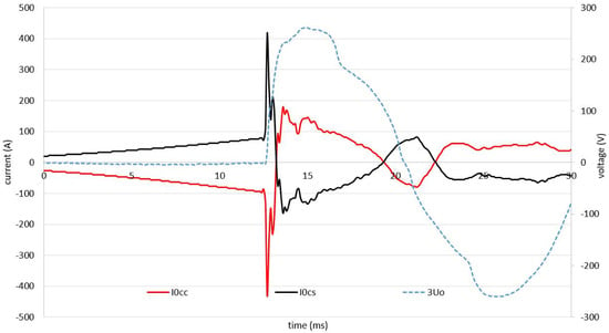
Figure 11.
Waveforms of currents in cable core and earthing system under phase-to-earth fault in underground cable line.
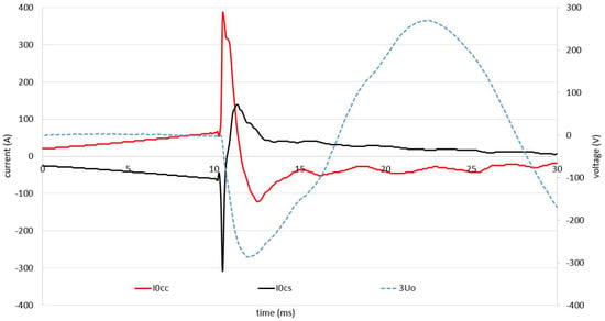
Figure 12.
Waveforms of currents in cable core and earthing system under phase-to-earth fault in overhead section.
Unfortunately, our analysis of the whole set of measurements shows that the statement regarding the is true, but not always—it is true for every measurement but the first earth fault in the underground cable and overhead section. It is believed that the reason for the low in the case of the very first earth fault in the underground cable line is wet soil and earthing systems during the network experiment, an environment characterized by high conductivity because of rainy conditions. The soil and earthing system has inductive character and therefore the transient current, which consists of high-frequency components, is susceptible to impedance changes []. The impedance of earth and earthing system depends on the water content. The water content may be changed as a result of direct contact with current—current flowing through earth under phase to earth fault conditions, particularly in vicinity of earthing systems [] or indirect contact with current—current flowing in cable line produce heat, which in turn may cause migration of water further away from the cable line []. Every earth fault lasted more than 1 s in order to observe both the transient and steady state component. The long duration of earth faults could impact water migration. As a result, less current flows through the cable screen and more current flows through the earthing system. One has to underline that the phenomenon is connected only with the very initial moment of earth fault occurrence and the under permanent earth fault remains intact. In case of the first moment of earth fault in overhead cable line, the is bigger what can be explained by the high conductivity of path between cable earthing system () and the of the pole of overhead line. The comparison of initial for different earth faults is presented in Table 1.

Table 1.
tRMS measured at the initial period of earth fault (average of 3 RMS measurements).
Analysis of the recorded waveforms (the list of records is presented in Table 1) allowed to specify another criterion for identification of line type under incipient phase to earth fault conditions. It is observed that when earth faults occur, in the underground cable line the local extremes in and currents occur at the same time, as presented in Figure 11. In the case of earth fault in the overhead section, the local extremes do not coincide, as presented in Figure 12. The approximate time difference between the currents local extremes is 1.5 ms. The observed relation is valid for any earth fault and proves the conceptual algorithm presented in the previous section. The measurements were also used to verify the effectiveness of the previously proposed locating schemes using the steady-state components of the earth faults. The previously proposed algorithm utilizes information about and to determine the approximate length of the underground cable line in which the phase-to-earth fault current flows. The values, which characterize the feeder used during the network experiment are 0.95 and <0.5 degree for earth fault in cable line whereas the values for earth fault in overhead line are 0.03 and 82 degrees. The measured results are very similar to the setting values (obtained using the simulation software) and allow for clear identification of the segment of feeder under stable phase to earth fault conditions. The analysis of the results presented in Table 2 allows concluding that in the case of stable earth faults >20 ms, the effectiveness of both algorithms is the same. However, the proposed algorithm allows determining the line under very short transient earth faults phase-to-earth fault conditions, which is the key advantage of the proposed algorithm.

Table 2.
Analysis of the waveforms and stable earth fault criterion.
6. Summary
Herein, we present theory and examples of transient earth faults. A methodology for classifying and locating earth faults in cable and mixed distribution feeders is presented. Two methods for pre-locating transient earth faults are presented. The first method is based on a comparison of the ratio of earth fault current in cable core— and cable screen earthing current during the first period of the earth fault. The second method is based on the comparison of local extremes of and . If local extremes in both currents occur at the same time, the transient earth fault can be classified as earth fault along the cable line, whereas the different numbers and high phase shift between local extremes indicate the fault along the overhead line. Network experiment confirms the validity of the proposed method. At the same time, one has to underline that the presented results refer to one cable-overhead feeder in which the cable length is small. In the case of longer cable lines, slight time shifts between local extremes are expected since additionally, the inductive current is observed. The smaller is the amplitude of current returning to 110 kV/15 kV substation neutral point through cable screens the bigger is the difference between zero-sequence current in cable core and cable screens. When currents are equal almost 100% returns through cable screens and the magnetic field created by currents cancel out (100% is not achieved because of the spatial distribution of magnetic fields). When the ratio becomes smaller the magnetic field is stronger and as a result, not only the conductive part, but also inductive part has to be considered. In order to locate the transient earth fault more precisely—determine a branch of the feeder under phase to earth fault conditions, it is proposed to use reference transients, which are obtained during operation of the distribution feeder. The transients are categorized and marked as the reference based on the analysis of the and under quasi-steady-state earth fault conditions (transient and one period of 50Hz waveform)—phase shift and ratio of 50 Hz components of the currents. Additionally, examples of analytical classification of earth faults are given, which may further increase the effectiveness of transient earth fault locating. The proposed algorithm can be implemented in earth fault protection relays or be used manually to troubleshoot problematic feeders in the distribution system network.
Author Contributions
Conceptualization, K.Ł.; methodology, K.Ł.; software, K.Ł. and B.O.; validation, B.O.; formal analysis, B.O.; investigation, K.Ł.; resources, K.Ł.; data curation, K.Ł.; writing—original draft preparation, K.Ł.; writing—review and editing, K.Ł. and B.O.; visualization, K.Ł. and B.O. All authors have read and agreed to the published version of the manuscript.
Funding
This research was funded by Poznan University of Technology under grant number 0711/SBAD/4456. The APC was funded by Poznan University of Technology.
Conflicts of Interest
The authors declare no conflict of interest.
References
- Linčiks, J.; Baranovskis, D. Single Phase Earth Fault Location in the Medium Voltage Distribution Networks. Sci. J. Riga Tech. Univ. Power Electr. Eng. 2009, 25, 13–18. [Google Scholar] [CrossRef][Green Version]
- Wang, X.; Zhang, H.; Shi, F.; Wu, Q.; Terzija, V.; Xie, W.; Fang, C. Location of Single Phase to Ground Faults in Distribution Networks Based on Synchronous Transients Energy Analysis. IEEE Trans. Smart Grid 2020, 11, 774–785. [Google Scholar] [CrossRef]
- Jamali, S.; Bahmanyar, A. A new fault location method for distribution networks using sparse measurements. Int. J. Electr. Power Energy Syst. 2016, 81, 459–468. [Google Scholar] [CrossRef]
- Niu, L.; Wu, G.; Xu, Z. Single-Phase Fault Line Selection in Distribution Network Based on Signal Injection Method. IEEE Access 2021, 9, 21567–21578. [Google Scholar] [CrossRef]
- Olejnik, B. Adaptive Zero-Sequence Overcurrent Criterion for Earth Fault Detection for Fault Current Passage Indicators in Resistor Grounded Medium Voltage Networks. IEEE Access 2021, 9, 63952–63965. [Google Scholar] [CrossRef]
- Roberts, J.; Altuve, H.J.; Hou, D. Review of Ground Fault Protection Methods for Grounded, Ungrounded, and Compensated Distribution Systems; SEL: Pullman, WA, USA, 2005. [Google Scholar]
- Skomudek, W. Analiza i Ocena Skutków Przepięć w Elektroenergetycznych Sieciach średniego i Wysokiego Napięcia; Oficyna Wydawnicza Politechniki Opolskiej: Opole, Poland, 2008. [Google Scholar]
- Pierre, B.J.; Arguello, B. Investment Optimization to Improve Power Distribution System Reliability Metrics. In Proceedings of the 2018 IEEE Power & Energy Society General Meeting (PESGM), Portland, OR, USA, 5–10 August 2018. [Google Scholar]
- Lorenc, J.; Musierowicz, K.; Kwapisz, A. Detection of the intermittent earth faults in compensated MV network. In Proceedings of the 2003 IEEE Bologna Power Tech Conference Proceedings, Bologna, Italy, 23–26 June 2003; Volume 2, p. 6. [Google Scholar] [CrossRef]
- Mäkinen, O. Method and Apparatus for Identifying Intermittent Earth Fault. EU Patent EP1682909A1, 26 July 2006. [Google Scholar]
- Musierowicz, K.; Lorenc, J.; Marcinkowski, Z.; Kwapisz, A. A fuzzy logic- based algorithm for discrimination of damaged line during intermittent earth faults. In Proceedings of the 2005 IEEE Russia Power Tech, St. Petersburg, Russia, 27–30 June 2005; pp. 1–5. [Google Scholar] [CrossRef]
- Wahlroos, A.; Altonen, J.; Uggla, U.; Wall, D. Application of novel cumulative phasor sum measurement for earth-fault protection in compensated MV-networks. In Proceedings of the 22nd International Conference and Exhibition on Electricity Distribution (CIRED 2013), Stockholm, Sweden, 10–13 June 2013; pp. 1–4. [Google Scholar] [CrossRef]
- Wahlroos, A.; Altonen, J. Application of novel multi-frequency neutral admittance method into earth-fault protection in compensated MV-networks. In Proceedings of the 12th IET International Conference on Developments in Power System Protection (DPSP 2014), Copenhagen, Denmark, 31 March–3 April 2014; pp. 1–6. [Google Scholar] [CrossRef]
- Pan, W.; Li, Y.; Sun, K.; Zhu, Z.; Li, X. Incipient Fault Location Method of Cable Based on Both-End Electric Quantities. IEEE Access 2020, 8, 219503–219512. [Google Scholar] [CrossRef]
- Qin, X.; Wang, P.; Liu, Y.; Guo, L.; Sheng, G.; Jiang, X. Research on Distribution Network Fault Recognition Method Based on Time-Frequency Characteristics of Fault Waveforms. IEEE Access 2018, 6, 7291–7300. [Google Scholar] [CrossRef]
- Owens, J.; Xiao, A.; Bonk, J.; DeLorme, M.; Zhang, A. Recent Development of Two Alternative Gases to SF6 for High Voltage Electrical Power Applications. Energies 2021, 14, 5051. [Google Scholar] [CrossRef]
- Lowczowski, K.; Lorenc, J.; Zawodniak, J.; Dombek, G. Detection and Location of Earth Fault in MV Feeders Using Screen Earthing Current Measurements. Energies 2020, 13, 1293. [Google Scholar] [CrossRef]
- Lowczowski, K.; Lorenc, J.; Andruszkiewicz, J.; Nadolny, Z.; Zawodniak, J. Novel Earth Fault Protection Algorithm Based on MV Cable Screen Zero Sequence Current Filter. Energies 2019, 12, 3190. [Google Scholar] [CrossRef]
- Olejnik, B. Doziemne zwarcia przerywane w sieci średniego napięcia. Pozn. Univ. Technol. Acad. J. Electr. Eng. 2017, 90, 101–112. [Google Scholar] [CrossRef]
- Hoppel, W.; Lorenc, J. Ogolna Ocena Sposobow Pracy Punktu Neutralnego Sieci Srednich Napiec. In Proceedings of the Wspolczesna Problematyka Sieci Srednich Napiec, Kornik, Poland, 16–18 October 2007. [Google Scholar]
- Handke, J. Wykorzystanie Kryterium Czestotliwosci Wlasnej Obwodu i Systemu Pomiarow Rozproszonych do Identyfikacji Parametrow Ziemnozwarciowych w Skompensowanej Sieci Sredniego Napiecia. Ph.D. Thesis, Poznan University of Technology, Poznan, Poland, 2010. [Google Scholar]
- Fan, Y.; Guang, L.; Yu, S.; Yongduan, X.; Hui, P.; Bingyin, X. Electrical Characteristics of Medium-voltage Distribution Network with Single-phase-to-ground Fault After Arc Extinction. Autom. Electr. Power Syst. 2019, 43, 134. [Google Scholar] [CrossRef]
- Chen, D.; Hu, B.; Li, Y.; Zhang, W.; Qi, Y.; Wang, R. Analysis of the Influence of Voltage Recovery Process on Line Selection Device When Single-phase Grounding Fault Is Removed. In Proceedings of the 2020 IEEE Sustainable Power and Energy Conference (iSPEC), Chengdu, China, 23–25 November 2020; pp. 1772–1777. [Google Scholar] [CrossRef]
- Łowczowski, K. Symulacja zjawisk ziemnozwarciowych w sieci SN uziemionej przez układ równoległy. Pozn. Univ. Technol. Acad. J. Electr. Eng. 2018, 157–167. [Google Scholar] [CrossRef]
- Benner, C.; Li, C.; Sabin, D.; Cooke, T.A.; Macleod, G.; Santoso, S.; Freitas, W.; Mousavi, M.; Torquato, R.; Grebe, T.; et al. Electric Signatures of Power Equipment Failures. 2018. Available online: https://grouper.ieee.org/groups/td/pq/data/downloads/Signatures_Equipment_Failures_V2018Dec.pdf (accessed on 7 November 2021).
- Enea Opeator. Elektroenergetyczne Linie Napowietrzne śRedniego Napięcia. 2017. Available online: https://www.operator.enea.pl/operator/info-o-sieci/standardy-w-sieci-dystrybucyjnej/22.01.2018/elektroenergetyczne-linie-napowietrzne-sredniego-napiecia.pdf?t=1516695338 (accessed on 7 November 2021).
- Olejnik, B.; Łowczowski, K. Techniczne metody poprawy współczynników SAIDI oraz SAIFI stosowane w sieci dystrybucyjnej. Pozn. Univ. Technol. Acad. J. Electr. Eng. 2016, 86, 165–176. [Google Scholar]
- Zawodniak, J.J.; Tryjanowski, P. Bird Protection in Medium Voltage Lines with Bare Wires. Autom. Elektr. Zakłócenia 2020, 11, 24–28. [Google Scholar] [CrossRef]
- Göcsei, G.; Németh, B.; Cselkó, R.; Berta, I. Bird protection on medium voltage power lines—An experimental study on the Hungarian grid. In Proceedings of the 2014 IEEE Electrical Insulation Conference (EIC), Philadelphia, PA, USA, 8–11 June 2014; pp. 460–464. [Google Scholar] [CrossRef]
- Škorpíková, V.; Hlaváč, V.; Krápek, M. Bird mortality on medium-voltage power lines in the Czech Republic. Raptor J. 2019, 13, 27–44. [Google Scholar] [CrossRef]
- Gális, M.; Naďo, L.; Hapl, E.; Šmídt, J.; Deutschová, L.; Chavko, J. Comprehensive analysis of bird mortality along power distribution lines in Slovakia. Raptor J. 2019, 13, 1–25. [Google Scholar] [CrossRef]
- Wang, L. The Fault Causes of Overhead Lines in Distribution Network. In Proceedings of the MATEC Web of Conferences, Shanghai, China, 28–29 May 2016; Volume 61, p. 02017. [Google Scholar] [CrossRef]
- Byrne, T. Humidity effects in substations. In Proceedings of the 2014 Petroleum and Chemical Industry Conference Europe, Amsterdam, The Netherlands, 3–5 June 2014; pp. 1–10. [Google Scholar] [CrossRef]
- Kulkarni, S.; Lee, D.; Allen, A.; Santoso, S.; Short, T. Waveform characterization of animal contact, tree contact, and lightning induced faults. In Proceedings of the IEEE PES General Meeting, Minneapolis, MN, USA, 25–29 July 2010; pp. 1–7. [Google Scholar]
- Kasztenny, B.; Voloh, I.; Jones, C.G.; Baroudi, G. Detection of Incipient Faults in Underground Medium Voltage Cables. In Proceedings of the 2008 61st Annual Conference for Protective Relay Engineers, College Station, TX, USA, 1–3 April 2008; pp. 349–366. [Google Scholar] [CrossRef]
- Edwards, A.; Kang, H.; Subramanian, S. Improved Algorithm for Detection of Self-clearing Transient Cable Faults. In Proceedings of the 2008 IET 9th International Conference on Developments in Power System Protection (DPSP 2008), Glasgow, Scotland, 17–20 March 2008. [Google Scholar]
- Steennis, E.; Buys, P.; Mehairjan, R.; Mehairjan, P.; Van der Wielen, P. Smart Cable Guard for PD-online monitoring of MV underground power cables in Stedin’s network. In Proceedings of the International Conference on Condition Monitoring and Diagnosis 2014, Jeju, Korea, 21–25 September 2014. [Google Scholar] [CrossRef]
- Louro, M.; Ferreira, L. Underground MV Network Failures’ Waveform Characteristics—An Investigation. Energies 2021, 14, 1216. [Google Scholar] [CrossRef]
- Kuisti, H.; Altonen, J.; Svensson, H.; Isaksson, M. Intermittent earth faults Challenge Conventional Protection Schemes. In Proceedings of the CIRED Conference, Nice, France, 1–4 June 1999. [Google Scholar]
- Wurm, M. Earth Fault Distance Localization in Inductive Earthed Networks by Means of Distance Protection Relays. In Proceedings of the 21st International Conference on Electricity Distribution, Frankfurt, Germany, 6–9 June 2011. [Google Scholar]
- Jain, A.; Archana, T.C.; Sahoo, M.B.K. A Methodology for Fault Detection and Classification Using PMU Measurements. In Proceedings of the 2018 20th National Power Systems Conference (NPSC), Tiruchirappalli, India, 14–16 December 2018; pp. 1–6. [Google Scholar] [CrossRef]
- Asman, S.H.; Ab Aziz, N.F.; Abd Kadir, M.Z.A.; Amirulddin, U.A.U. Fault Signature Analysis for Medium Voltage Overhead Line Based on New Characteristic Indices. In Proceedings of the 2020 IEEE International Conference on Power and Energy (PECon), Virtual Conference, 7–8 December 2020; pp. 198–203. [Google Scholar] [CrossRef]
- Wischkaemper, J.A.; Benner, C.L.; Don Russell, B.; Muthu Manivannan, K. Application of advanced electrical waveform monitoring and analytics for reduction of wildfire risk. In Proceedings of the ISGT 2014, Washington, DC, USA, 19–22 February 2014; pp. 1–5. [Google Scholar] [CrossRef]
- Küchler, B.; Schmidt, U.; Hänsch, J. Harmonic Current Distribution in Grounding Systems of Cabled Medium Voltage Grids during Single-Pole Ground Fault. Energies 2021, 14, 1110. [Google Scholar] [CrossRef]
- Carlsson, F.; Etherden, N.; Johansson, A.; Wall, D.; Fogelberg, A.; Lidstrom, E. Advanced Fault Location in Compensated Distribution Networks. In Proceedings of the CIRED Workshop, Helsinki, Finland, 14–15 June 2016. [Google Scholar]
- Schott-Szymczak, A.; Walczak, K. Analysis of Overvoltages Appearing in One-Sidedly Ungrounded MV Power Cable Screen. Energies 2020, 13, 1821. [Google Scholar] [CrossRef]
- Morańda, H.; Sztolcman, M.; Walczak, K.; Mościcka-Grzesiak, H. Enlargement of fingerprint in procedure of defects recognition in oil-paper insulation using time parameters of PD. In Proceedings of the XIV International Symposium on High Voltage Engineering, Beijing, China, 25–29 August 2005; pp. 1–4. [Google Scholar]
- Sikorski, W. Development of Acoustic Emission Sensor Optimized for Partial Discharge Monitoring in Power Transformers. Sensors 2019, 19, 1865. [Google Scholar] [CrossRef] [PubMed]
- Petit, M.; Bastard, P. Simulation of a zero-sequence relay for a distribution network with EMTP-RV. Discrimination between fault current and magnetizing inrush current. In Proceedings of the International Conference on Power Systems Transiens (IPST’05), Montreal, Canada, 19–23 June 2005. [Google Scholar]
- Gouda, O.E.; Farag, A. Bonding Methods of Underground Cables. 2015. Available online: https://www.researchgate.net/publication/283119570_Bonding_methods_of_underground_cables?channel=doi&linkId=562b649608ae22b170335067&showFulltext=true (accessed on 7 November 2021).
- Lowczowski, K. Detection of Earth Faults in MV Cable Lines Using Electrical Quantities Measured in Cable Screens. Ph.D. Thesis, Poznan University of Technology, Poznan, Poland, 2020. [Google Scholar]
- Benato, R.; Sessa, S.D.; Guglielmi, F.; Partal, E.; Tleis, N. Ground Return Current Behaviour in High Voltage Alternating Current Insulated Cables. Energies 2014, 7, 8116–8131. [Google Scholar] [CrossRef]
- Colella, P.; Pons, E.; Tommasini, R. MV Ground Fault Current Distribution: An Analytical Formulation of the Reduction Factor. In Proceedings of the 2017 IEEE International Conference on Environment and Electrical Engineering and 2017 IEEE Industrial and Commercial Power Systems Europe (EEEIC/I&CPS Europe), Milan, Italy, 6–9 June 2017. [Google Scholar]
- Cables, S.D.; Equipment. Metal Theft. 2012. Available online: https://www.spenergynetworks.co.uk/userfiles/file/scottishpower_cables_equipment_metal_theft.pdf (accessed on 7 November 2021).
- Habrych, M.; Wisniewski, B.; Miedziński, A.; Lisowiec, Z.; Fjałkowski, G. HDI PCB Rogowski coils for automated electrical power system applications. IEEE Trans. Power Deliv. 2017, 33, 1536–1544. [Google Scholar] [CrossRef]
- Meliopoulos, A.P.; Moharam, M.G. Transient Analysis of Grounding Systems. IEEE Trans. Power Appar. Syst. 1983, PAS-102, 389–399. [Google Scholar] [CrossRef]
- Nti, I.K.; Appiah, A.Y.; Nyarko-Boateng, O. Assessment and Prediction of Earthing Resistance in Domestic Installation; Wiley: Hoboken, NJ, USA, 2019. [Google Scholar]
- Anders, G.J. Rating of Electric Power Cables in Unfavorable Thermal Environment; John Wiley and Sons: Hoboken, NJ, USA, 2005. [Google Scholar]
Publisher’s Note: MDPI stays neutral with regard to jurisdictional claims in published maps and institutional affiliations. |
© 2022 by the authors. Licensee MDPI, Basel, Switzerland. This article is an open access article distributed under the terms and conditions of the Creative Commons Attribution (CC BY) license (https://creativecommons.org/licenses/by/4.0/).