Abstract
It is vitally important that a transmission network provides a continuity of electricity to end users and that the transmission system operator prioritizes its safety and reliability. This article presents the possibilities of using multi-track overhead lines with varying levels of rated voltage, run on a common support structure. This solution would ensure safe operation of the system, reduce the area used for the construction of new overhead lines, and, at the same time increase the transmission network capacity. This article focuses on the method of modeling overhead lines for the analysis of electromagnetic transient states that occur during non-simultaneous disturbance phenomena. This article presents the idea of multi-circuit, multi-voltage lines and their validity of use in power systems. An analysis of electromagnetic transient states for non-simultaneous disturbances in multi-path, multi-voltage lines is presented. This analysis has been made on the basis of a network model, using ATP-EMTP (Alternative Transients Program-Electromagnetic Transients Program) software for solutions, for a Polish power system. Particular attention was paid to the most unfavorable phenomena appearing in the modeled system. The impact of the emerging electromagetic transients in multi-path, multi-voltage lines was evaluated. It was shown that the specificity and rapid changeability of the emerging electromagnetic transients and lack of a universal model of the overhead power line make the analyses of electromagnetic transients highly labor-intensive and time-consuming. Each change is connected with the necessity to create new line models for the study of electromagnetic transient states dependent on many factors.
1. Introduction
For many years, observations have been made of the activities in the widely understood field of power engineering related to satisfying the constantly growing demand for electricity. Every year, the expectations of the consumer concerning the supply and quality of electricity increases [1]. These requirements are affected by the processes of power sector decentralization and marketization, for which economic criteria are important. Therefore, there is a requirement to redefine the current approach of operation, planning and control of operation. Due to the continual progress of network structure decentralization, development of local electricity sources made up of various forms of primary energy, power availability, end user expectations and technical requirements, power system operation must be transformed into a highly dynamic process characterized by a high degree of variety in function and decision-making. Therefore, high flexibility of operation and continuous adaptation to emerging technical requirements is required. Maintaining an appropriate level of flexibility in the management of power system operation is possible by equipping the network and substation structures with properly equipped and coordinated automated control, measurement, connection and protection [2].
1.1. The Scope of the Article
The article focuses on multi-circuit, overhead lines with varying levels of rated voltage, hereinafter referred to as multi-circuit, multi-voltage lines. The considerations are generic, and the analyses carried out are based on examples of the Polish power system. This article consists of three main chapters containing a short literature review, introducing solutions currently used aimed at ensuring stable and safe operation.
These solutions are necessary for a variety of reasons. There are increasingly frequent fluctuations in the power flow in the network, characterized by several factors. One factor is the high variability of transmitted power and another is its directionality. This change in directionality results from changes in conditions of generation (due to the connection of an increasing number of new sources of renewable energy) and the lack of modernization of network structures that could ensure an appropriate load distribution.
Section 2 presents the method of overhead line modeling for the purposes of conducting electromagnetic analysis of transients occurring in overhead lines. This section presents a method of creating a model of the network system for the requirements of the electromagnetic transient analysis with non-simultaneous short-circuit disturbances appearing in overhead lines; in the case of this article, in multi-path lines with varying levels of rated voltage. The next section, Section 3, looks at the advantages and disadvantages of multi-circuit, multi-voltage lines as well as the supporting structures used for these lines. The next section, Section 4, presents the analyzed system created for the analysis of electromagnetic transient states occurring in multi-path, multi-voltage lines with the occurrence of non-simultaneous short-circuit disturbances.
Electromagnetic transient states have high dynamics and a short duration (in the order of 10−6 ÷ 10−3) so the selection of appropriate models for power system components is very important.
1.2. Background
The increase in the number of currently available renewable energy sources results in an increase in the probability of network disturbances. The increased demand for electricity and the dynamic development of the distribution network have led to a reduction in the margin of transmission capacity for High Voltage (HV) and Extra High Voltage (EHV) networks. Stagnation in the area of transmission networks may have a negative effect, inter alia, extending the time of commissioning new power units, as well as the construction of new transmission lines, the construction time of which is several times longer. This is mainly due to the legal requirements that make it difficult to obtain land for constructing new HV and EHV overhead lines coupled with increasing investment costs in the transmission sector. The poorly developed structure of the transmission network limits possible switching activities, which is vital during disturbances [3].
The transmission network capacity is increasing due to the growing demand for electricity. However, the lack of modernization of the network infrastructure is a factor causing higher failure rates due to high usage, and with high overloads, system failures are highly likely. Therefore, it is necessary to modernize or build new transmission lines [4], which, however, is associated with high investment cost and a number of legal requirements. The construction of new transmission lines is associated with many significant problems, the most important of which is to obtain the consent of the local community, then to purchase the land and then to obtain expert opinions on the impact upon the natural environment. These factors may drastically extend the implementation time or lead to the complete abandonment of plans to build new lines and are global concerns. In reality, the biggest problem is, therefore, the choice of route and the type of new overhead line [5], as well as the environmental, social, legal, technical and economic aspects.
The limitations of these aspects largely speak in favor of increasing the transmission voltage using a common support structure. It should be remembered that overhead power lines impact the environment through the emission of electromagnetic fields [6] and noise. The area beneath the wires may also be affected as well as the local area if these permissible levels are exceeded. The affected area is called the technological belt.
The technological belt is an area where there are restrictions related to property development. The width of the technological belt of an overhead power line depends on the rated voltage and the series of poles used [7]. Table 1 shows the width of the technological belt for 220 kV and 400 kV overhead power lines used in the Polish power system [8].

Table 1.
The width of the technological belt for the 220 kV and 400 kV overhead power lines used in the Polish power system.
The 220 kV and 400 kV lines, created last century, use the Polish standard, PN-E-051000-1: 1998 [9], which specifies the requirements for the minimum permissible distances of power line cables from intersections and proximity to buildings and other objects such as roads. These requirements, unfortunately, translate into limitations into how property in the immediate vicinity of the overhead line can be used. This treatment is necessary to ensure public safety and the correct operation of the overhead line. It can be assumed that the requirements for the standard horizontal distance will be met for most buildings, which are located approximately 8–9 m from the extreme projection of the 400 kV line phase conductor and approximately 6–7 m for the line with a rated voltage of 220 kV.
In order to carry out appropriate modernization, repair and maintenance operations, the technological belt is a necessity for the reliable operation of power transmission lines. It allows them to maintain their technical efficiency and ensures safe operation of lines, people and infrastructure.
To carry out any work on overhead lines, access to a property with suitable land is necessary, and in the case of major renovations or repairs, access to all such land in the technological belt is necessary. The facts discussed above are the reason why communities have a negative attitude and oppose construction of new lines in their neighborhood. The topic raises a lot of controversy, which is why it is so important to search for new solutions that could facilitate the investor’s request for new installations [10,11].
A solution that could potentially solve the above problem may be to run overhead lines with different voltage levels on common support structures. The use of an already existing infrastructure gives the investor a great opportunity to implement the investment and shorten the construction time, which is a great economic benefit. The use of the so-called multi-circuit, multi-voltage lines has, therefore, become a very popular solution. However, this does not come without some technical problems. It should be noted that the use of multi-path, multi-voltage lines favors the appearance of magnetic couplings between varying voltages [12]. The voltage-diversified paths located on the common support structure are also supplied from different sources, which causes considerable complications in identifying fault states.
In general, overhead power lines are run along routes parallel to already existing overhead lines. However, despite the complications that can result from unfavorable electromagnetic interactions, there are routes on which two lines are run, e.g., 220 kV and 400 kV, which are run on a common support structure. This means that the size of the technological belt is reduced by a quarter compared to what would be required for two separate overhead lines with appropriate rated voltages of 220 kV and 400 kV. Running linear lines in the form of multi-circuit lines with different voltages not only allows the width of the occupied technological belt to be reduced, but also increases the yield in the form of transmitted energy [10].
2. Modeling Multi-Circuit, Multi-Voltage Transmission Lines
The ability to determine voltage and current requires the knowledge of the mathematical representation of particular system components as well as the model of the entire power system during conditions when there is a fault or a switch. Known numerical methods, electronic computing techniques or physical representation for the study of transient states of the power system at natural frequencies [12] can be used if information about these models is known.
Requirements relating to the creation of an optimal power transmission line model for the assumed purpose of the analysis force the overhead line to be treated as an element of the system, which is not subject to a decrease in size. Accurate mapping of the transmission line model is necessary to ensure the correct reconstruction of transients during the occurrence of complex disturbances containing high frequency components and this is important during modeling. In practice, problems with the correct representation of the power transmission line [12] always occur during simulation studies. The overhead line model, depending on set goals, should meet the requirements allowing results to be obtained with appropriate accuracy.
In reality, the power transmission line (Figure 1) is the only element of the power system with parameters evenly distributed along its length, therefore appropriate numerical methods are required.
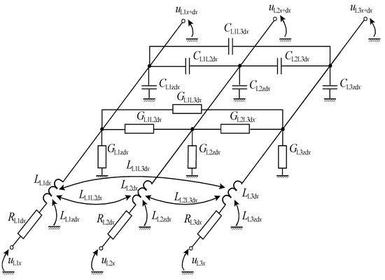
Figure 1.
Model of the transmission line section with the length dx [12].
The representation of a line as lumped components connected in series, taking into account inductive and capacitive couplings, may lead to erroneous results, causing the appearance of artificial components that do not exist in real systems [4,13]. The oscillations that appear during numerical calculations may also be the result of not taking into account the skin effect and the influence of frequency on the parameters of the modeled line. Table 2 presents the requirements for modeling lines in transmission networks during numerical calculations.
Table 2.
Requirements of the transmission line model depending on the purpose of the research [12].
Modeling lines with frequency-dependent distributed parameters is taken into account by applying Marti’s model [14], which is the optimal solution with regard to the speed and accuracy of calculations. This model uses an approximation to the impedance-frequency relationship with a system of chain-connected RC elements.
In order to carry out a correct analysis, the interactions between individual phases should be taken into account due to the occurring electromagnetic couplings and the dependence of the parameters of the equivalent diagram for that frequency. This procedure is extremely difficult due to the fact that when many phenomena occur simultaneously, the range of frequency changes may be very wide.
Based on a literature review, it should be stated that there is no universal model for all types and states of disturbances [3,15,16]. Each change in the structure of the power system is associated with the need to create new line models for the study of electromagnetic transient states depending on many factors. These factors include:
- the type and duration of the examined disturbance;
- the expected range of changes in the frequency of the transient;
- the structure of the analyzed part of the power system;
- the preservation of the characteristic properties of individual elements of the real line in the model.
It is necessary to use simplifications in the models of individual elements of the power system, regardless of the size of the part that has been analyzed. The procedure for creating the representation of the needs of electromagnetic transient analyzes of the power system is described in the literature [16,17].
For electromagnetic transient analyses, the only appropriate approach is to use the overhead line model with spatially distributed and frequency dependent parameters [15,16,18]. The literature studies show that the use of power line models with lumped and frequency-independent parameters leads to erroneous results during the analysis of electromagnetic transient states. This results in an incorrect interpretation of a tested phenomenon. In addition, when short-circuit disturbances or switching operations are simulated, the decay time of the oscillation components is significantly extended and distortions are seen in the largest instantaneous values of voltage and current signals. These effects are not seen for the values obtained for line models with distributed and frequency dependent parameters. A detailed description of the consequences of using incorrect power line models for the needs of transient analyses can be found in the literature [16,17,19].
When modeling power lines, it is also important to correctly map the discontinuity points characterized by a step change in the impedance of the system (e.g., transition from an overhead line to a cable line or vice versa). Correct mapping of these sensitive areas is invaluable in the analysis of transient states, especially when determining the maximum instantaneous values of voltages and currents (e.g., when determining overvoltage factors). The complexity and difficulty of the problem of fast-changing electromagnetic disturbances is confirmed by the fact that since the development of the first methods of determining substitute patterns for the above-mentioned phenomena, it has not been possible to create a universal method of creating substitute patterns for the entire duration of electromagnetic transient states [16,20,21,22].
3. Multi-System Lines with Different Voltage Levels
The idea behind using multi-system, multi-voltage lines is to run several lines with different rated voltages on one support structure [3,4]. This means using the technological area of an existing overhead line. This solution is used as a result of the following cases, when [23]:
- the line is run in unfavorable environmental conditions;
- there is a problem with obtaining permission to build;
- the area is highly urbanized.
Dedicated supporting structures (towers) are used for multi-system, multi-voltage lines. The tower is designed for a given multi-voltage line. In most cases, these towers are taller than standard poles intended for one voltage level. The dimensions of the structure result from the necessity to maintain appropriate insulation gaps between individual current circuits [24]. Compared to standard designs, however, the differences are small. The main difference is the area covered, as it is of great importance in order to reduce the occupied technological belt. The width of the technological belt for two high voltage overhead lines is significant and almost twice the width of the technological belt occupied by a three-circuit double-voltage line with a vertical arrangement of working conductors [3]. This proves the suitability of using multi-circuit, multi-voltage lines when implementing investments for a new line (Figure 2).
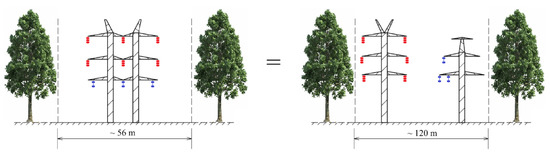
Figure 2.
Comparison of the used technological belt for a multi-circuit, multi-voltage overhead line (three-circuit double-voltage line 2 × 400 kV) using the basic solution.
The width of the overhead line protection belt is affected by the intended use of the area as well as the value of the rated voltage and the number of current paths. It follows that the width of the process strip in the case of multi-path, multi-voltage lines is very diverse. The classification of multi-path, multi-voltage lines can be made due to the following criteria:
- the rated voltage of the current paths;
- the arrangement of working conduits;
- the functions performed in the power system;
- the rated frequencies of the current paths.
Table 3 Multi-circuit, multi-voltage lines for EHV and HV, located in the Polish power system.
Table 3.
Multi-circuit and multi-voltage lines for HV and EHV in the Polish power system [3].
Multi-circuit, multi-voltage lines can be distinguished by the rated voltage of the current paths and the system of working conductors. Multi-path, multi-voltage lines are also distinguished by the rated frequency of individual current paths; lines, which have the same rated frequency in every line (usually fn = 50 Hz or fn = 60 Hz) dominate. There are also multi-system and multi-voltage lines, where one of the paths can also have the nominal frequency value equal to fn = 16.7 Hz (Switzerland, Germany) [23].
4. Electromagnetic Transients for Non-Simultaneous Short-Circuit Disturbances in Multi-System, Multi-Voltage Lines
Not only does the reduction in the technological belt have a positive effect on the environment and natural landscape, but it also allows for a significant saving of time when implementing new investments. The use of multi-system, multi-voltage lines also has an economic impact. Like any investment, it also has disadvantages, which include the need to design appropriate support structures. Calculations for the design of these structures are much more complicated than for traditional poles. This is due to the loads from each current path, according to the standards requirements, and various combinations of broken conductors of individual phases needing to be taken into account, as if they are not, they can cause complex short-circuit disturbances in the system [10]. In three/four-system lines, it is necessary to perform up to several hundred calculations. After designing the support structure, further problems may arise resulting from the operation of the applied multi-system, multi-voltage lines, as each time any maintenance, modernization, or repairs are carried out, the covered track must be switched off. Switching off all current paths is a significant interference in the operation of the power system. It should be mentioned that the planned and accidental shutdown of a multi-system, multi-voltage line significantly changes the flow of power locally in the power grid, increasing the load on other lines, therefore it is very often difficult to obtain the approval of the Transmission System Operator. Nevertheless, multi-circuit, multi-voltage lines must come with a guarantee of the reliability of energy supply, therefore it is very important from the economic, technical and operational points of view to correctly design the line, as well as to conduct continuous analyses of disturbance cases that may lead to incorrect operation.
The occurrence of disturbances results in the overlap of reflected surge waves in multi-wire systems, causing phenomena that may cause unnecessary activation of protections. Transient phenomena occur in overhead lines as a result of short-circuit disturbances occurring in other current paths operating on the same tower structure with different voltage levels. The occurrence of a disturbance can lead to an unnecessary cascade of disconnection of the lines; as mentioned it is advantageous from the point of view of the correct operation of the system and the need to maintain a reliable electricity supply. The fact that each of the current paths is connected to a different system causes many problems for the location and removal of faults.
The simulation analysis was performed using the ATP-EMTP program with a line model with distributed frequency-dependent parameters [25]. The remaining part of the modeled system was replaced with an equivalent (Figure 3), the structure and parameters of which were determined using standard optimization methods [5]. In recent years, simulations of electromagnetic transient states have been of great interest to designers as well as the analyses of power system operation, and have, therefore, become a very important area of research. There is an ever increasing demand for electricity and increase in social awareness of protecting the natural environment, resulting in people looking into newer and better solutions to increase the use of electricity from renewable energy sources. Due to its complexity, the issue of electromagnetic transients is also important for the correct operation of power systems and for reducing the risk of blackouts.
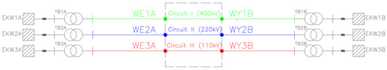
Figure 3.
Network system model with a Three-circuit Transmission Line designed in ATP-EMTP program.
The analyses are intended to solve the problems of analytical evaluation of the emerging transient states of electromagnetic nature that accompany complex short-circuit disturbances that can drastically affect the operation of multi-system lines with different voltage levels. This paper focuses on the states that constitute a potential threat to the correct operation of the power system. It should be noted that the lack of, and difficulties in identifying, potential dangers may have a huge impact on the appearance of uncontrolled disturbances leading to possible system failure [26,27].
4.1. Analysis of a Multi-Circuit, Multi-Voltage Line
As part of this work, simulation analyses of non-simultaneous, short-circuit disturbances in multi-system lines with different voltage levels were investigated. The electromagnetic transient states during short-circuit disturbances were analyzed. Complex non-simultaneous short-circuits are identified at different points in time. In this work, a simulation model was used to investigate electromagnetic fault states in the network structure, which included a multi-system line with different voltage levels. The subject of the analysis is a fragment of the 110 kV, 220 kV and 400 kV network, the diagram of which is presented in Figure 3. This network includes power stations TB1A, TB1B, TB1C and three overhead lines, marked as lines No. 1–3 with different voltage levels. System No. 1 is a 400 kV overhead line powered from TB1A, system No. 2 is a 220 kV overhead line powered from TB2B, and track No. 3 is 110 kV lines powered from TB3C. On a section of 5 km, 30 km, 200 km, there are 400 kV, 220 kV and 110 kV multi-circuits, multi-voltage lines located on a common support structure, with each line being led individually. The possible arrangement of the conductors in the line is shown in Figure 4a,b showing one of the possible solutions for running the lines. The location of the 110 kV line under the 220 kV and 400 kV lines is advantageous due to the use of land available for the location (Figure 4a). The use of support structures in a vertical and horizontal arrangement (Figure 4b), similarly to a vertical arrangement, makes it possible to make optimal use of the area.
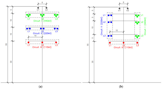
Figure 4.
The possible arrangement of the conductors in the line: (a) a horizontal of the phase conductor configuration of transmission line; (b) vertical and horizontal of the phase conductor configuration of transmission line.
As part of this work, the network system shown in Figure 3 was used, and a detailed simulation of emerging disturbances was carried out on this network. The above-mentioned research was related to the disturbances that may occur in a real power system.
The analysis of electromagnetic transient states during non-simultaneous short-circuit disturbances was carried out for a three-circuit, three-voltage line of varying lengths. The analyzed network system consists of:
- three-circuit, three-voltage line with rated voltages equal to 400 kV + 220 kV + 110 kV;
- Circuit I-single-circuit overhead line with a rated voltage of 400 kV supplied from the EKW1A and EKW1B equivalent;
- Circuit II-single-circuit overhead line with a rated voltage of 220 kV supplied from the EKW2A and EKW2B equivalent;
- Circuit III-single-circuit overhead line with a rated voltage of 110 kV supplied from the EKW2A and EKW2B equivalent.
The support structures were modeled as strong towers. Table 4 presents the data of phase conductors and ground wires for a simple system containing 400 kV, 220 kV and 110 kV lines. Table 5 shows the data for the cables used in the modeled multi-system lines with different voltage levels.
Table 4.
Parameters of phase conductors and ground wires for a simple system of 440 kV, 220 kV and 110 kV lines.
Table 5.
The data for the cables used in the modeled multi-system lines with different voltage levels.
4.2. Analysis of Electromagnetic Transient States for Not Simultaneous Faults Occurring in a Network System
Figure 5, Figure 6, Figure 7 and Figure 8 show transients for current and voltage in the damaged and “healthy” phases of multi-system lines with different voltage levels. Selected voltage transients shown in Figure 6, Figure 7 and Figure 8, respectively, are presented at the beginning of the 110 kV, 220 kV and 400 kV lines (point WE1A, WE2A and WE3A), during a three-phase non-simultaneous short-circuit at the end of the voltage of 400 kV line (point WY1B).
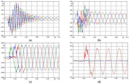
Figure 5.
Current waveform in the damaged and “healthy” phases of a multi-system lines with different voltage levels: (a) for transmission line 110 kV (point WE3B); (b) for transmission line 220 kV (point WE2B); (c) for transmission line 400 kV (point WE1B); (d) in phase L1 for transmission line 110kV, 220 kV and 400 kV (point WY1B).
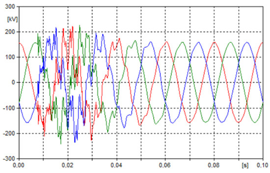
Figure 6.
Voltage waveform of a multi-system line with different voltage levels for transmission line 110 kV.

Figure 7.
Voltage waveform of a multi-system line with different voltage levels for transmission line 220 kV.
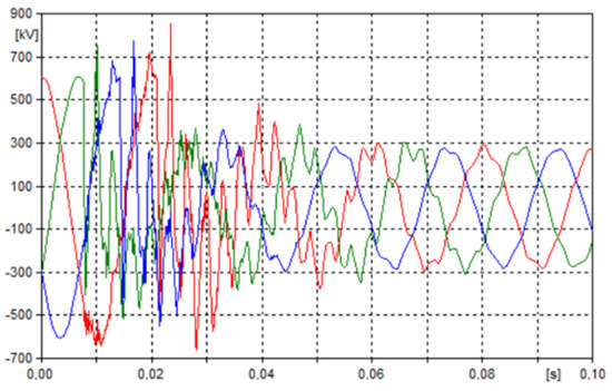
Figure 8.
Voltage waveform of a multi-system line with different voltage levels for transmission line 400 kV.
The influence of individual parameters and operating conditions on the peak overvoltages in the system during simultaneous short-circuits is well documented in the literature. It should be mentioned that the characteristics of simultaneous short-circuit disturbances, where the maximum overvoltages occur at the moment of the maximum voltage of the damaged phases, are not important during non-simultaneous short-circuits. Therefore, it is concluded that they cannot be directly transferred to the occurring non-simultaneous disturbances. The combination of the circuit breaker phase closing delays can result in an overlapping of high frequency free components and the possibility of creating conditions conducive to the appearance of peaks in each phase. This is due to the emerging high frequency components being added to the base voltage. This results in the appearance of dependencies between the components that can significantly affect the resultant voltage peak values.
For very short lines and short-circuits located in close proximity to the measuring point, there is a greater probability that a component with the maximum pulsation with a greater amplitude will be added to the base voltage. However, it should be remembered that they will be attenuated faster than in long lines when short circuited.
The analyses conducted showed a huge number of factors that can significantly affect the disturbances appearing in the analyzed network system. However, it was noticed that often, when there was a change in particular parameters for a given network system configuration there was no significant change in the values of the occurring overvoltages. More often, there has been a situation where there has been a change in, e.g., the time of the peak voltage during an emerging electromagnetic transient. This situation shows that when the numerical analysis is based on the determination of the closing time delay, the ranges of switching angles where overvoltage maximum may occur, is time-consuming. Due to this fact, despite the great interest in electromagnetic transients appearing in multi-system lines with different voltage levels, the analyses for these states for non-simultaneous disturbances are rare.
Local and general phenomena are also factors that influence the maximum value of the overvoltage. Local factors are deterministic and affect the level of emergence. These factors include:
- structure and parameters of the system: in this case, the parameters of the overhead transmission line and the power system (the relationship between the positive and zero sequence impedance as well as resistance and reactance) play a major role;
- influence of the load and operating conditions of the system: in the normal system operation mode;
- general (probabilistic) factors include:
- o
- the type of disturbance that occurs: at the moment of the occurrence of a short circuit without grounding, high-frequency components occur, which cause disturbances in a given phase. In the event of a ground fault, a situation occurs in which the amplitude of the components of healthy phases may be greater than in the phase affected by the disturbance.
- o
- distance from the disturbance: it is a factor related to local parameters; the line length. The time of the surge wave to pass the path from the fault location to the first discontinuity point causing the wave reflection, specifying the amplitude and damping time of the frequency components;
- o
- the moment of the disturbance occurrence: it should be noted that at the moment of the short-circuit, the voltage reaches its maximum in the given phase. In the event of a non-simultaneous short circuit, this finding may lose its credibility due to the fact that in the phase with the delayed short circuit, the components may have a greater amplitude at the time of the voltage phase shift.
Interconnection failures in multi-system transmission lines are dangerous. Faults appearing in this type of solution, such as, e.g., a break of one phase with a given rated voltage, may affect the occurrence of overvoltages in neighboring systems. Thus, a polyphase short circuit can occur with or without grounding. It should be noted that during such a short circuit, extreme current values appear. This phenomenon is particularly evident in lines with a lower rated voltage level for the current path located on the same support structure. This situation is shown in Figure 9.
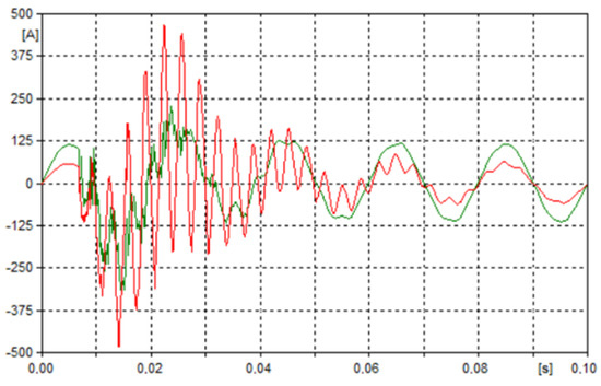
Figure 9.
Current waveform of a multi-system lines for transmission line 110 kV (red waveform) and 220 kV (green waveform).
The obtained results confirm the results obtained in the works [3,28] for conducting electromagnetic analysis of transients occurring in multi-circuit, multi-voltage overhead lines.
Similar studies were carried out on the basis of other line models. In the article [4] of electromagnetic transient analyses are carried out for the line model with lumped and frequency-independent parameters. For electromagnetic transient analyses, the appropriate approach is to use the overhead line model with spatially distributed and frequency dependent parameters [15,16].
The impact of individual parameters and operating conditions on the peak of the surge in the system during simultaneous faults is well developed in the literature. The conclusion of these results cannot be directly transferred to non-simultaneous faults. The combination of delays closing phases in the circuit breaker may result in the overlapping of the high-frequency free components and the possibility of the creation of conditions conducive to the maximum value in each phase.
Correctness relating to simultaneous fault that the maximum overvoltages occur at the moment of maximum value of the faulted phases (although this is not valid during non-simultaneous faults), as high frequency components are added to a base voltage value. This relationship between components can significantly impact on the peak value of the resultant voltage.
The frequency of components is dependent on the location and type of circuit and is inversely proportional to the length of the line. For the faults located close to the measurement point, and for very short lines, there exists the greater possibility that the maximum value component of the pulsations of higher amplitude will be added to the basic voltage.
5. Summary and Conclusions
Undoubtedly, the use of multi-system lines with different voltage levels has its disadvantages, which include the need to design new support structures. Calculations for the design of these structures are much more complicated than for traditional support structures. This solution also has advantages, which include the reduction in the electro-magnetic field strength in the vicinity of the designed overhead line and a significant reduction in the width of the technological belt. The solution of arranging several circuits on the same tower has become widely used, whether there are circuits that operate at the same voltage or at different rated voltages, or even put alongside AC and DC circuits [29]. There are many cases where the concentration of energy sources (e.g., renewable energy sources) is located far from the points of consumption and such a solution is more than welcome. The support structures hosting multi-circuit lines can be a common support for them on longer or shorter routes.
In the case of multi-circuit, multi-voltage overhead lines, the most convenient solution is to dispose the higher voltage circuits at a higher height, and those of lower voltage (or voltages) at the bottom part of the tower. Due to its carrying capacity, the extra high voltage line is more important, and its damage due to conductors breaking of high voltage circuits would have a much greater economic impact. Furthermore it is also associated with an electric and magnetic field on the ground, since increasing the distance toward intense field sources is beneficial.
Faults appearing in multi-circuit, multi-voltage overhead lines may affect the occurrence of overvoltages in neighboring systems. The amplitude of current can achieve extreme values, which can be very dangerous first of all for the 110 kV line and for devices connected to this line. The extreme values of current surges and overvoltages in phases not affected by a short-circuit and in the phases affected by the disturbance for the tested network system, show the importance of such situations, in which a non-simultaneous disturbance occurs for a power system. The continual increase in the demand for electricity, the development of power systems by connecting them to new, renewable local sources and the desire to reduce the negative impact on the environment by building new lines on a common structure are of key importance when considering the occurrence of non-simultaneous short-circuit disturbances.
The appearance of such complex disturbances in multi-system lines with different voltage levels may lead to unforeseen shutdowns of entire line sequences. Simulation research has shown that this phenomenon is very dangerous for the job of the line and the power system. The use of multi-circuit, multi-voltage lines is justified when there is a lack of space for the construction of a new line on existing land. We deal with such situations in the case of power stations located in the vicinity of large cities and industrial areas. Taking into account the intensive development of areas around the cities and the planned development of the power grid in Poland, the use of multi-voltage lines is therefore justified, and such solutions will be required and used more often in the future.
The increasing number of multi-circuit, multi-voltage overhead lines enables an increase in the power transferred over long distances. There is the danger of the occurrence of the high-value overvoltages, where a worst case scenario would be an intersystem fault [28].
Conducting analyses of simultaneous and non-simultaneous disturbances allows appropriate models of supporting structures to be found as the very act of arranging the phases is of great importance for the operation of a given line. The use of the ATP-EMTP software (dedicated to the simulation of electromagnetic transient states) allows the verification of non-simultaneous transients during non-simultaneous disturbances in multi-circuit, multi-voltage transmission lines.
Author Contributions
D.Z. and P.S. contributed equally to this work and all of its stages and elements. All authors have read and agreed to the published version of the manuscript.
Funding
This research received no external funding.
Institutional Review Board Statement
Not applicable.
Informed Consent Statement
Not applicable.
Data Availability Statement
No new data were created or analyzed in this study. Data sharing is not applicable to this article.
Conflicts of Interest
The authors declare no conflict of interest.
References
- Szczerbowski, R. Energy security of Poland—Energy mix and energy efficiency. Polityka Energetyczna 2013, 16, 35–47. [Google Scholar]
- Szablicki, M.; Rzepka, P.; Halinka, A.; Sowa, P. Diagnosis of challenges for power system protection—Selected aspects of transformation of power systems. In Proceedings of the International Conference Modern Electric Power Systems (MEPS), Wroclaw, Poland, 9–12 September 2019. [Google Scholar]
- Kumala, R. Identification of Disturbances in Multi-Circuit, Different Level Voltage Power Lines. Doctoral Dissertation, Silesian University of Technology, Gliwice, Poland, 2016. (In Polish). [Google Scholar]
- Nazarcik, T.; Benesova, Z. Analysis of the transients on the multi-circuit overhead transmission line. J. Electr. Eng. 2018, 68, 476–481. [Google Scholar]
- Skomudek, W. Development of compact high and extra-high voltage overhead power lines. Acta Energ. 2011, 1, 11–12. [Google Scholar]
- Feng, G.; Wang, Y.; Zhang, B. Study on Electromagnetic Environment of Multi-circuit Transmission Lines on Same Tower. In Proceedings of the 2008 Joint International Conference on Power System Technology and IEEE Power India Conference, New Delhi, India, 12–15 October 2008. [Google Scholar]
- Standard PN-EN 50341-2-22:2016-04 Overhead Electrical Lines Exceeding AC 1 kV—Part 2–22: National Normative Aspects (NNA) for Poland (Based on EN 50341-1:2012). 2016. Available online: https://standards.iteh.ai/catalog/standards/clc/f88050ec-0acb-4984-8334-c6efb6cdc03f/en-50341-2-22-2016 (accessed on 25 November 2021).
- Budowa Linii Elektroenergetycznej 400 kV Ostrołęka-Stanisławów (Liniaostrolekastanislawow.pl). Available online: https://liniaostrolekastanislawow.pl/charakterystyka-inwestycji/#:~:text=Niekt%C3%B3re%20odcinki%20linii%20220%20kV%20przbiegaj%C4%85%20w%20pobli%C5%BCu,a%20nie%20jak%20dotychczas%202%20x%2025%20metr%C3%B3w (accessed on 25 November 2021). (In Polish).
- Standard PN-E-051000-1: 1998. Available online: https://sklep.pkn.pl/pn-e-05100-1-1998p.html (accessed on 25 November 2021).
- Costea, M.; Baran, I. Benefits and problems raised by multi-circuit overhead lines operation. In Proceedings of the 2021 12th International Symposium on Advanced Topics in Electrical Engineering (ATEE), Bucharest, Romania, 25–27 March 2021; pp. 1–6. [Google Scholar]
- Nazarcik, T.; Benesova, Z. Modelling of the transients on the multi-circuit EHV/HV overhead transmission lines. In Proceedings of the 18th International Conference on Computational Problems of Electrical Engineering (CPEE), Kutna Hora, Czech Republic, 11–13 September 2017; pp. 1–4. [Google Scholar]
- Macha, D. Electromagnetic Transients in Transmission Lines Powering Local Systems. Doctoral Dissertation, Silesian University of Technology, Gliwice, Poland, 2019. (In Polish). [Google Scholar]
- Sowa, P.; Macha, D. Electromagnetic switching transients in transmission line cooperating with the local subsystem. Int. J. Geomater. 2020, 19, 180–189. [Google Scholar] [CrossRef]
- Marti, J.R. Accurate modelling of frequency-dependent lines in electromagnetic transient simulations. IEEE Trans. Power Appar. Syst. 1982, PAS-101, 147–157. [Google Scholar] [CrossRef]
- Das, J.C. Transients in Electrical Systems—Analysis, Recognition and Mitigation; McGraw Hill Professional: New York, NY, USA, 2010. [Google Scholar]
- Sowa, P. Dynamic Equivalents for Simulation of Transients in Power System; Wyd. Politechniki Śląskiej: Gliwice, Poland, 2011. [Google Scholar]
- Sowa, P.; Kumala, R.; Łuszcz, K. Modeling of power system components during electromagnetic transients. Int. J. Innov. Sci. Eng. Technol. 2014, 1, 715–719. [Google Scholar]
- Hevia Orlando, P. Alternative Transients Program-Comparison of Transmission Line Models; Can/Am EMTP News—Voice of the Canadian/American EMTP User Group: Santa Fe, Argentina, 1998; Volume 98-1. [Google Scholar]
- Łuszcz, K.; Sowa, P. Equivalent for electromagnetic transient calculation in power system with multiple transmission line. Energy Power Eng. 2013, 5, 1449–1455. [Google Scholar]
- Canadian/American EMTP User Group. Alternative Transient Program Rule Book; EMTP Centre: Leuven, Belgium, 1987–1995. [Google Scholar]
- Dommel, H.W. Electromagnetic Transients Program. Reference Manual (EMTP Theory Book); Bonneville Power Administration: Portland, OR, USA, 1986. [Google Scholar]
- Rosołowski, E. Computer Methods of Analyzing Electromagnetic Transient States; Wyd. Politechniki Wrocławskiej: Wrocław, Poland, 2009. [Google Scholar]
- Sowa, P. Overvoltages in the transmission line with the different voltage level working on the same tow er construction. Zesz. Nauk. PŚl. Elektr. 1994, 137, 149–160. [Google Scholar]
- Novitskiy, A.; Westermann, D. Interaction of multi-circuit overhead transmission lines of different voltages located on the same pylons. In Proceedings of the 2012 Electric Power Quality and Supply Reliability, Tartu, Estonia, 11–13 June 2012; pp. 1–4. [Google Scholar]
- Mahseredjian, J.; Dinavahi, V.; Martinez, J.A. Simulation tools for electromagnetic transients in power systems: Overview and challenges. IEEE Trans. Power Deliv. 2009, 24, 1657–1669. [Google Scholar] [CrossRef]
- Sun, Y.; Cheng, L.; Huang, J.; Zhang, Q.; Huang, Y.; Huang, Y. Comparison of the influence of different types of faults on four-circuit transmission lines on the same tower. In Proceedings of the 2018 IEEE 2nd International Electrical and Energy Conference (CIEEC), Beijing, China, 4–6 November 2018; pp. 386–391. [Google Scholar]
- Wang, F.; Yang, M. Fast electromagnetic transient simulation for over-voltages of transmission line by high order Radau method and V-transformation. Gener. Transm. Distrib. IET 2016, 10, 3639–3645. [Google Scholar] [CrossRef]
- Kumala, R.; Sowa, P. Intersystem faults in the coupled high-voltage line working on the same tower construction. Prz. Elektrotech. 2019, 24, 141–144. [Google Scholar]
- Stanojev, O.; Garrison, J.; Hedtke, S.; Franck, C.M.; Demiray, T. Benefit analysis of a hybrid HVAC/HVDC transmission line: A Swiss case study. In Proceedings of the 2019 IEEE Milan Power Tech, Milan, Italy, 23–27 June 2019. [Google Scholar]
Publisher’s Note: MDPI stays neutral with regard to jurisdictional claims in published maps and institutional affiliations. |
© 2022 by the authors. Licensee MDPI, Basel, Switzerland. This article is an open access article distributed under the terms and conditions of the Creative Commons Attribution (CC BY) license (https://creativecommons.org/licenses/by/4.0/).