Article

Sequence Impedance Modeling and Optimization of MMC-HVDC Considering DC Voltage Control and Voltage Feedforward Control

Department of Electrical Engineering, Nanjing University of Aeronautics and Astronautics, No.29 Yudao Street, Nangjing 211106, China
*
Author to whom correspondence should be addressed.
Energies 2022, 15(24), 9649; https://doi.org/10.3390/en15249649
Submission received: 8 November 2022 / Revised: 28 November 2022 / Accepted: 16 December 2022 / Published: 19 December 2022

Abstract

:
The dynamic performance of the DC bus significantly influences the impedance characteristics of MMC and the system stability in a high-voltage direct current system. However, most of the existing MMC-HVDC system stability research simplifies the DC side as an ideal voltage source and ignores the impacts of voltage feedforward control, which affects the accuracy and practicability of stability analysis. In this paper, a sequence impedance model considering both DC voltage control and voltage feedforward control is developed, and the necessity of considering DC control and voltage feedforward control for MMC-HVDC stability analysis is illustrated. Then, the impact of control parameters on MMC-HVDC impedance is discussed, and the boundary conditions of control parameters are also derived. Finally, a method of control parameters design and impedance optimization for MMC-HVDC based on the stability boundary is proposed. Compared to the traditional optimization method, the system stability is further improved by the impedance optimization method proposed this paper.

1. Introduction

The modular multilevel converter (MMC) has the advantages of significant redundancy, less harmonic content, and high conversion efficiency [1,2,3], and has been widely used in high-voltage direct current (HVDC) transmission. However, in the actual process, several MMC-HVDC projects have reported broadband resonance accidents with frequencies covering a dozen Hz to several hundred Hz [4,5,6,7,8], which seriously affect the safe and stable operation of the power system and cause huge losses.
Grid-connected system stability analysis based on impedance modeling has now been recognized as an effective method and widely used in the stability analysis of MMC grid-connected systems. Several scholars have established a more accurate MMC impedance modeling using the multi-harmonic linearization method [9,10,11,12] or the multi-harmonic state space method (HSS) [13,14,15]. However, in the above models, the DC side of MMC-HVDC is often simplified as an ideal DC source which means the dynamic of the DC bus voltage control will be ignored. In the analysis of permanent magnet synchronous generators (PMSG) integrated into a power grid system, it has been found that the DC voltage control is an essential factor in determining the impedance characteristics of the machine side PMSG. In practical MMC-HVDC projects, there must be a current-source converter station to support the DC-side voltage [14]; the impact of DC voltage control on the impedance characteristics of the converter station cannot be ignored. Thus, it is worth studying the DC voltage control of the MMC impedance model and its impact on the MMC impedance characteristics as well as grid-connected system stability.
Voltage feedforward control is also commonly used in practical projects to mitigate the imbalance of the grid voltage and improve the performance of the converter [14,15,16]. Most of the existing impedance modeling and stability analysis of MMC-HVDC ignore the influence of voltage feedforward control. However, voltage feedforward control has a non-negligible impact on the impedance characteristics and system stability of MMC-HVDC [17], so it is necessary to analyze the grid stability of MMC-HVDC and its impedance optimization method under the premise of considering voltage feedforward.
The impedance optimization of the converter can effectively improve the impedance characteristics of the system at the resonance frequency and reduce the risk of resonance [15]. Studies have been conducted to optimize the design of control parameters such as current control [18,19] and voltage feedforward control [20,21], which affect the stability of MMC-HVDC integrated systems on high-frequency ranges. Due to the complex structure, the impedance influence factors of MMC-HVDC are quite complex, especially in the sub-/super-synchronous frequency. Numerous control loops, including DC voltage control and voltage feedforward control, are coupled with each other, which makes it challenging to optimize the impedance characteristic of MMC-HVDC and improve grid-connected system stability [22,23].
To address the problem of ignoring DC voltage control and voltage feedforward control in the existing stability analysis of the MMC-HVDC integrated system, an impedance optimization method based on the impedance characteristic considering DC voltage control and voltage feedforward control is proposed in this paper to enhance the system stability. The rest of this paper is organized as follows. An MMC sequence impedance modeling considering DC voltage control and voltage feedforward control is present in Section 2. The influencing factors of control parameters are discussed in Section 3. In Section 4, the effects of DC voltage control and voltage feedforward control on the stability of the system are discussed. In Section 5, an MMC-HVDC impedance optimization method based on stability boundary design is proposed to effectively improve the system stability.

2. Impedance Modeling of MMC-HVDC Considering DC Voltage Control

A typical power and control circuit of MMC-HVDC is shown in Figure 1. Each phase of MMC-HVDC consists of an upper arm and a lower arm, where both arms contain n submodules (SM1 ~ SMn) and an arm inductor L. Each submodule is in a half-bridge topology with a module capacitor Cm. The output voltages and currents of MMC-HVDC are denoted as vsx and isx (x = a, b, c), the voltage of DC side is denoted as vdc, and the three-phase upper arm currents and lower arm currents are denoted as ixu and ixl (x = a, b, c). The typical controls of MMC-HVDC include the DC voltage control, phase current control, PCC voltage feedforward control, circulating current suppression control (CCSC), and phase-locked loop (PLL) to generate θ [12]. Hd(s), Hi(s), Hc(s), and Hθ(s) represent proportional-integral (PI) regulators of DC voltage control, phase current control, CCSC and PLL.
In order to eliminate the adverse effects of high harmonics in the grid, a voltage feedforward controller is usually adopted to filter out the high harmonics of the grid in practical projects; the voltage feedforward controller Hf(s) can be expressed as:
H f ( s ) = k f ω f s + ω f
where kf is the voltage feedforward coefficient, and ωf is the cut-off frequency of the low-pass filter.
In addition, existing studies usually take the DC side as an ideal voltage source to simplify modeling, however, this simplification may lead to inaccurate analysis results of MMC-HVDC. This paper also focuses on the effects of DC voltage control on MMC-HVDC impedance characteristics.
Based on the power conservation law of the DC side and AC side, the small-signal instantaneous power of MMC-HVDC can be expressed as:
p ^ d c = 2 p ^ C x + 2 p ^ L x + p ^ o
where p ^ C , p ^ L , and p ^ o represent the instantaneous power of equivalent capacitance, the inductance of the upper arm, and the instantaneous output power of AC side, respectively. p ^ d c denotes the side instantaneous power of the DC side which can be expressed as (3)–(6):
p ^ C = 1 2 x = a , b , c ( Y c V C x v ^ C x + V C x Y c v ^ C x ) = 6 T 4 v ^ c a
p ^ L = 1 2 x = a , b , c ( Z l I x i ^ x + I x Z l i ^ x ) = 6 T 3 i ^ a
p ^ o = x = a , b , c V s x i ^ s x + I s x v ^ s x = 6 T 1 i ^ a + 6 T 2 v ^ s a
p ^ d c = V d c i ^ d c + I d c v ^ d c = V d c T 5 i ^ a + I d c v ^ d c
where Zl and Yc respectively denote the arm inductance impedance and equivalent capacitance admittance at small-signal harmonic frequencies. VCx, Ix, Vsx, Isx, Vdc, and Idc denote the steady-state harmonic matrix obtained by the Toplitz transform of ixu, vCx, isx, vsx, idc, and vdc, respectively. v ^ C x , i ^ x , v ^ s x , i ^ s x , v ^ d c , and i ^ d c denote the small-signal harmonic vectors of MMC equivalent capacitance voltage, arm current, output voltage and current, and voltage and current of the DC side; the nonzero elements in T1 ~ T5 are expressed as (A1) (Appendix A).
Combining Equations (2)–(6), the small-signal harmonic vectors of DC voltage can be expressed as:
v ^ dc = H 1 i ^ a + H 2 v ^ s a + H 3 v ^ c a
where
H 1 = I d c 1 ( 6 T 1 + 6 T 3 V d c T 5 ) , H 2 = 6 I d c 1 T 2 , H 3 = 6 I d c 1 T 4
Based on the dq control structure of MMC-HVDC, the small-signal vector of the insertion index can be modeled as follows:
{ m ^ d = K i i ^ sq H i i ^ sd + H d v ^ dc + H f v ^ s m ^ q = K i i ^ sd H i i ^ sq + H v v ^ s
where the red part in Equation (8) represents the effects of DC voltage control and feedforward control on the small-signal vector of the insertion index. i ^ sd and i ^ sq denote the small-signal harmonic vectors of the output current in the dq coordinate system. Ki represent dq-frame decoupling coefficient of phase current control. Hi, Hd, and Hf are 7 × 7 matrices as shown:
H i = d i a g ( H i ( s + j n ω 1 ) | n = 3 , 2 , 1 , 0 , 1 , 2 , 3 )
H d = d i a g ( H d ( s + j n ω 1 ) | n = 3 , 2 , 1 , 0 , 1 , 2 , 3 )
H f = d i a g ( G f ( s + j n ω 1 ) | n = 3 , 2 , 1 , 0 , 1 , 2 , 3 )
Combined with Equations (7) and (8), the linearized small-signal harmonic vector of the insertion index in abc coordinates is shown as:
m ^ u = G 1 i ^ u + G 2 v ^ s + G 3 v ^ s
where
G 1 = ( U Q 3 H 3 ) 1 ( Q 1 + Q 3 H 1 ) G 2 = ( U Q 3 H 3 ) 1 ( Q 2 + Q 3 H 2 ) G 3 = ( U Q 3 H 3 ) 1 Q v 2
the nonzero elements in Q1, Q2, Q3, and Qv2 are expressed as (A2)–(A5) (Appendix A).
After considering the DC voltage control, the MMC-HVDC small-signal of the power stage is changed to:
{ v ^ u = Z c ( M u i ^ u + I u m ^ u ) i ^ = Y l ( 1 2 v ^ d c v ^ s M u v ^ u V u m ^ u )
where Mu, Iu, and Vu denote the matrices of steady-state signals of the insertion index, arm current, and equivalent capacitive voltage obtained by the Toeplitz transform, and v ^ u denotes the small-signal harmonic vector of the equivalent capacitive voltage.
Combining Equations (12) and (13), MMC-HVDC admittance matrix Y considering DC voltage control and voltage feedforward control can be obtained.
Y = ( U Y l ( 0.5 H 1 M Z c M + ( 0.5 H 3 M Z c I V ) G 1 ) ) 1 Y l ( 0.5 H 2 U + ( 0.5 H 3 M Z c I V ) G 2 )
where the MMC-HVDC conductance matrix Y is a 7 × 7 matrix and the (4, 4) elements of Y represent the transfer function between the MMC-HVDC output side voltage at fp frequency and the bridge arm current at the same frequency, so the positive and negative sequence impedance of the MMC-HVDC considering DC voltage control can be defined as
Z p ( s ) = 1 2 Y ( 4 , 4 )
Z n ( s ) = Z p ( s )
In order to verify the accuracy of the established MMC-HVDC impedance modeling, the MMC-HVDC model including DC voltage control, current control, voltage feedforward control, loop control, and phase lock control was built based on Matlab/Simulink, and the specific simulation parameters are shown in Table 1. 
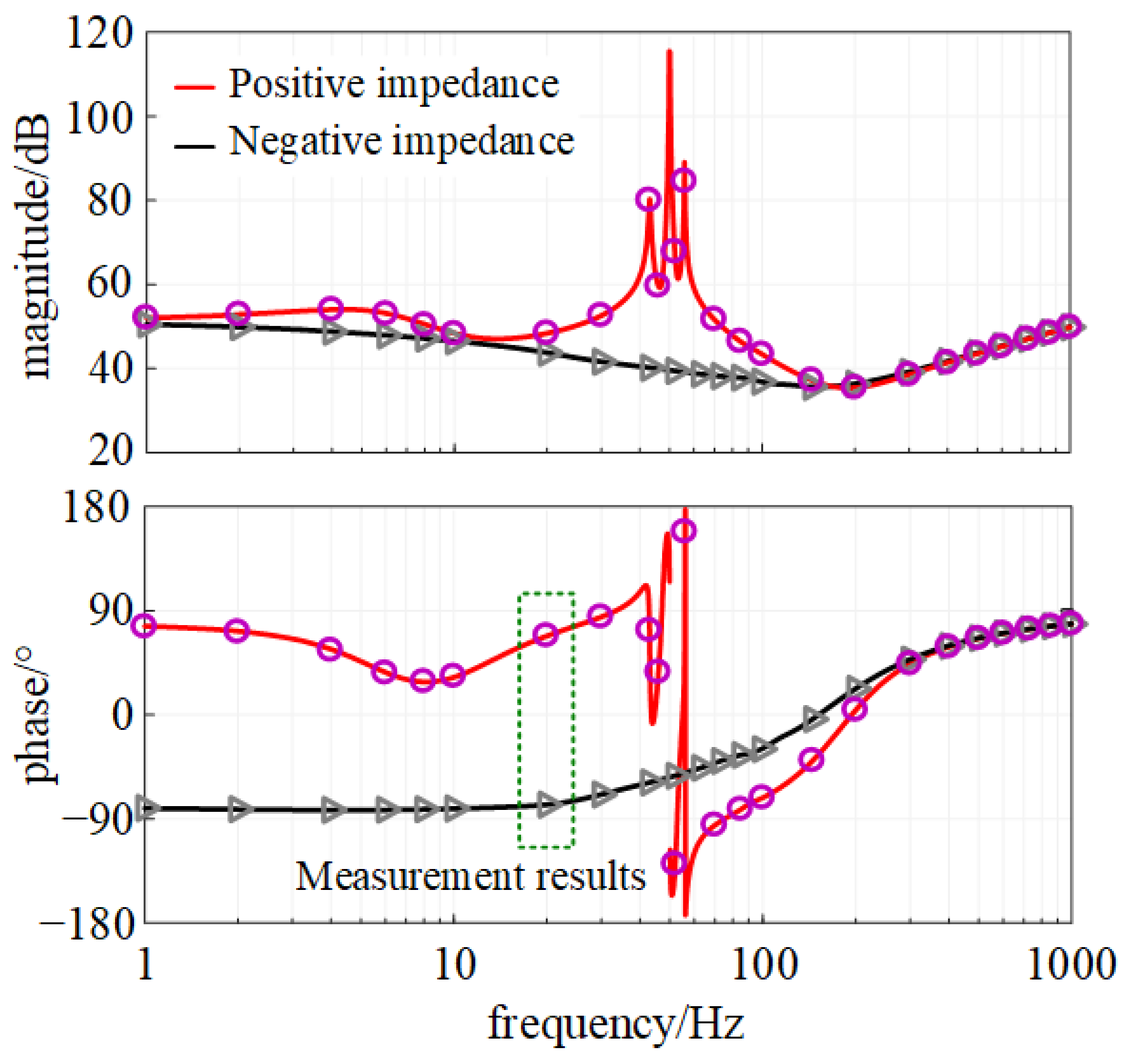
Figure 2 shows the comparison between the analytical and measurement results of both the positive and negative MMC-HVDC impedance. The simulated results are consistent with the analytical results, which confirms the accuracy of the developed MMC-HVDC impedance model.
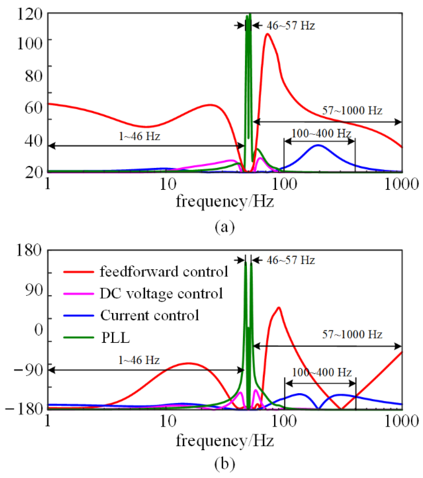
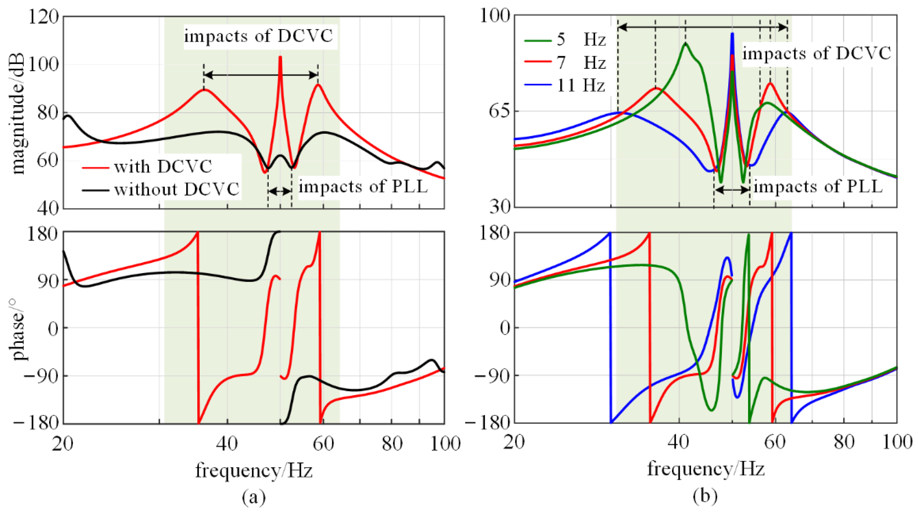
It can be observed that there are apparent differences between the positive and negative sequence impedance of MMC-HVDC; the positive sequence impedance increases with the frequency and the impedance amplitude and phase angle curve change significantly. In the frequency range of 20–80 Hz, the MMC-HVDC impedance is mainly affected by DC voltage control and PLL, and the impedance shows two symmetrical resonance peaks centered on the fundamental frequency. In the range of 80–400 Hz, the MMC-HVDC impedance is dominated by the current loop integrator. In the frequency range above 400 Hz, the MMC-HVDC impedance is mainly influenced by the filter and shows the damping characteristic. The positive and negative sequence impedance of the MMC-HVDC differs significantly in the low-frequency band, but with the increase in frequency both impedance curves gradually coincide.

3. MMC-HVDC Impedance Characteristic Analysis

3.1. Sensitivity Analysis of MMC-HVDC Impedance

Multiple controllers of MMC-HVDC are coupled with each other to affect the impedance characteristics of MMC-HVDC. Different controls dominate impedance characteristics of MMC-HVDC in their respective frequency ranges. In this section, impedance sensitivity is introduced to quantify the impacts of controllers on MMC-HVDC impedance.
From the above impedance modeling analysis, it can be seen that the impedance characteristics of the MMC-HVDC are affected by multiple controllers. The influence of controllers on impedance characteristics can be quantified by the impedance sensitivity. Impedance sensitivity can be refined as impedance magnitude sensitivity HMωα and impedance phase sensitivity HPωα to represent the influence of different controller parameters on magnitude and phase of MMC-HVDC impedance, respectively. The impedance magnitude and phase sensitivity of controller α are shown in Equations (17) and (18).
H M ω α ( s ) = lim Δ ω α 0 | | Z ( ω α + Δ ω α , s ) | | Z ( ω α , s ) | | Δ ω α
H P ω α ( s ) = lim Δ ω α 0 | Z ( ω α + Δ ω α , s ) Z ( ω α , s ) | Δ ω α
where Z(ωα,s) represents the MMC-HVDC impedance with the parameter of controller α is ωα, and Z(ωα + Δωα,s) represents that the parameter of controller α changes to ωα + Δωα.
Figure 3 depicts the impedance magnitude and phase sensitivity of the voltage feedforward coefficient, bandwidth of the current controller, DC voltage controller, and PLL control of the MMC-HVDC. The larger value of the sensitivity curve indicates that the corresponding controller has a greater effect on the impedance characteristics of MMC-HVDC.
In Figure 3, the impedance sensitivity of voltage feedforward control is significantly greater than other controllers in the frequency bands of 1 Hz ~ 46 Hz and 57 Hz ~ 1000 Hz, which means that the voltage feedforward coefficient dominates the impedance characteristics of MMC-HVDC in this frequency range. Voltage feedforward control will more greatly affect the magnitude of MMC-HVDC impedance at the frequency closer to the fundamental frequency. Similarly, the above rule can also be found on the effect of voltage feedforward control on the phase of MMC-HVDC impedance in the high-frequency range.
The impedance sensitivity of PLL and DC voltage control are more significant in the frequency band near the fundamental frequency (46 Hz ~ 57 Hz), indicating that the impedance characteristics of the MMC-HVDC are mainly influenced by PLL and DC voltage control, which is consistent with the existing findings.
The impedance sensitivity of the PLL and DC voltage control is approximately zero on the frequency range (1 Hz ~ 46 Hz, 57 Hz ~ 1000 Hz), where the voltage feedforward control plays a dominant role in the MMC-HVDC impedance characteristics mentioned above. This indicates that different controllers dominate impedance characteristics of MMC-HVDC in the different frequency ranges.
The output current control bandwidth is also located in the frequency range dominated by the voltage feedforward. At the cut-off frequency of the control bandwidth, the impedance sensitivity of the output current control is relatively improved, but still less than the voltage feedforward control, indicating that the MMC-HVDC impedance characteristics may be affected by more than one controller in some frequency ranges, but the influence degree of controllers is different.
In summary, the impedance characteristics of MMC-HVDC is affected by multiple control loops; the effect of different controls on MMC-HVDC impedance characteristics are different. Voltage feedforward control plays a dominant role in most frequency ranges.

3.2. Impacts of DC Voltage Control on Impedance Characteristics

Figure 4a compares MMC-HVDC impedance response with and without DC voltage control under the power and control parameters shown in Table 1. The DC voltage control affects the impedance characteristic mostly around the fundamental frequency (20 ~ 65 Hz): the impedance considering DC voltage control introduces a primary resonance peak at the fundamental frequency and a pair of secondary resonance peaks at both sides of the fundamental frequency (46.8 Hz and 56.5 Hz). Furthermore, the distance of frequency of the two secondary resonance peaks (9.7 Hz) is almost the same as the bandwidth of the DC voltage control (10 Hz). The impedance magnitude of MMC-HVDC increases significantly, while the impedance angle jumps from 180° to −180° at the resonance frequency.
Figure 4b compares the impedance response of the MMC-HVDC under different DC voltage control bandwidths. All the impedances of MMC-HVDC with different DC voltage bandwidths have a primary resonance peak at the fundamental frequency and a pair of secondary resonance peaks. The frequency offset between the two secondary resonant peaks increases with the increase in the DC voltage control bandwidth.

3.3. Impacts of Voltage Feedforward Control Coefficient on Admittance Characteristics

Figure 5a compares the characteristics of MMC-HVDC admittance (the reciprocal of impedance) considering and ignoring voltage feedforward control with the control parameters shown in Table 1. The amplitude of MMC-HVDC admittance with voltage feedforward control (denoted as YMMCo in Figure 5a) is significantly reduced compared with that without feedforward control admittance (denoted as YO). Near the fundamental frequency, both admittance curves almost overlap. With frequency increases, the effect of voltage feedforward control gradually decreases, and the magnitude of YMMCo approaches that of YO. It should be noted that the phase of equivalent admittance of voltage feedforward control (denoted as Ylf) is greater than 90° in the low-frequency range (1 Hz ~ 34 Hz) and less than −90° in the middle-frequency range (72 Hz ~ 160 Hz), which will lead YMMCo to exhibit extra negative-damping characteristics (1 Hz ~ 8 Hz and 74 Hz ~ 133 Hz). Similarly, in the frequency band where Ylf provides damping effects (34 Hz ~ 44 Hz), YMMCo also changes from negative-damping to positive-damping characteristics when voltage feedforward is considered.
Figure 5b compares the impedance responses of the MMC-HVDC with different voltage feedforward coefficient kf. As kf decreases, the magnitude of Ylf gradually decreases, which leads the magnitude of YMMCo closer to that of Yo. Similarly, with a smaller kf, the impacts of voltage feedforward control on the phase of impedance also decrease, and the frequency ranges where Ylf shows the negative-damping characteristic become narrower.

4. Stability Analysis of MMC-HVDC Integrated System

Based on the developed impedance model in 
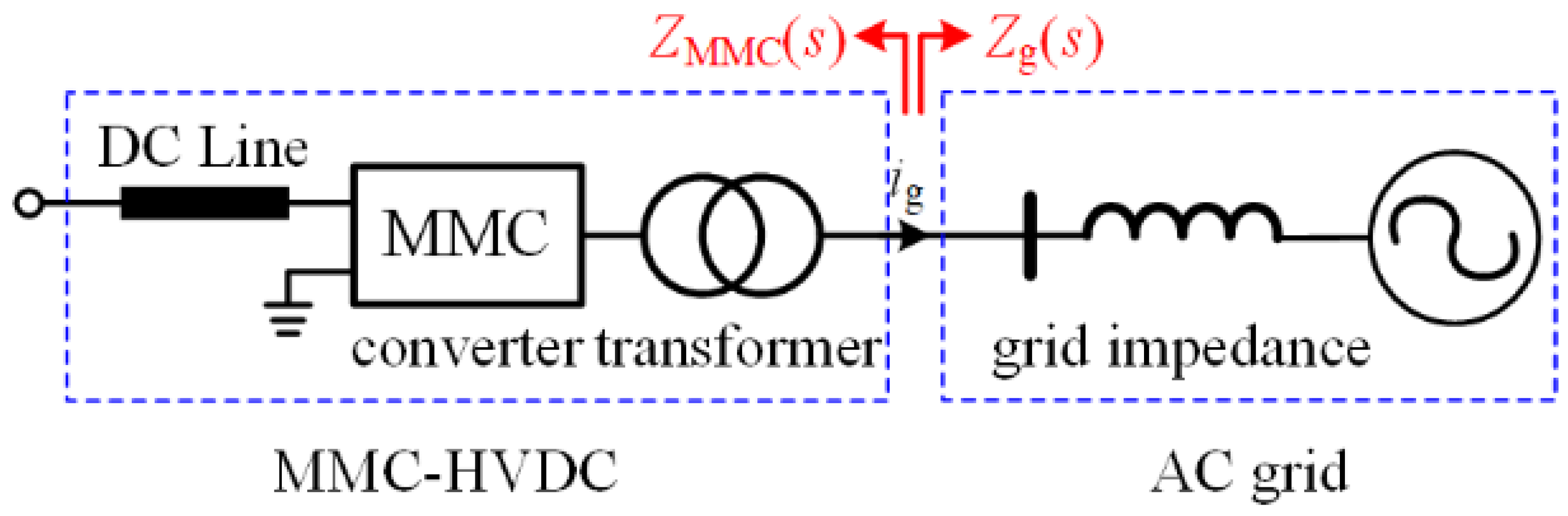
Section 2, the impedance-based analysis method can be used to evaluate the stability of the MMC-HVDC integrated system. The configuration of the MMC-HVDC integrated system used to analyze the stability is presented in Figure 6, where the impedance of MMC-HVDC is denoted as ZMMC(s) and the grid impedance is denoted as Zg(s), and the parameters of MMC-HVDC are presented in Table 1.
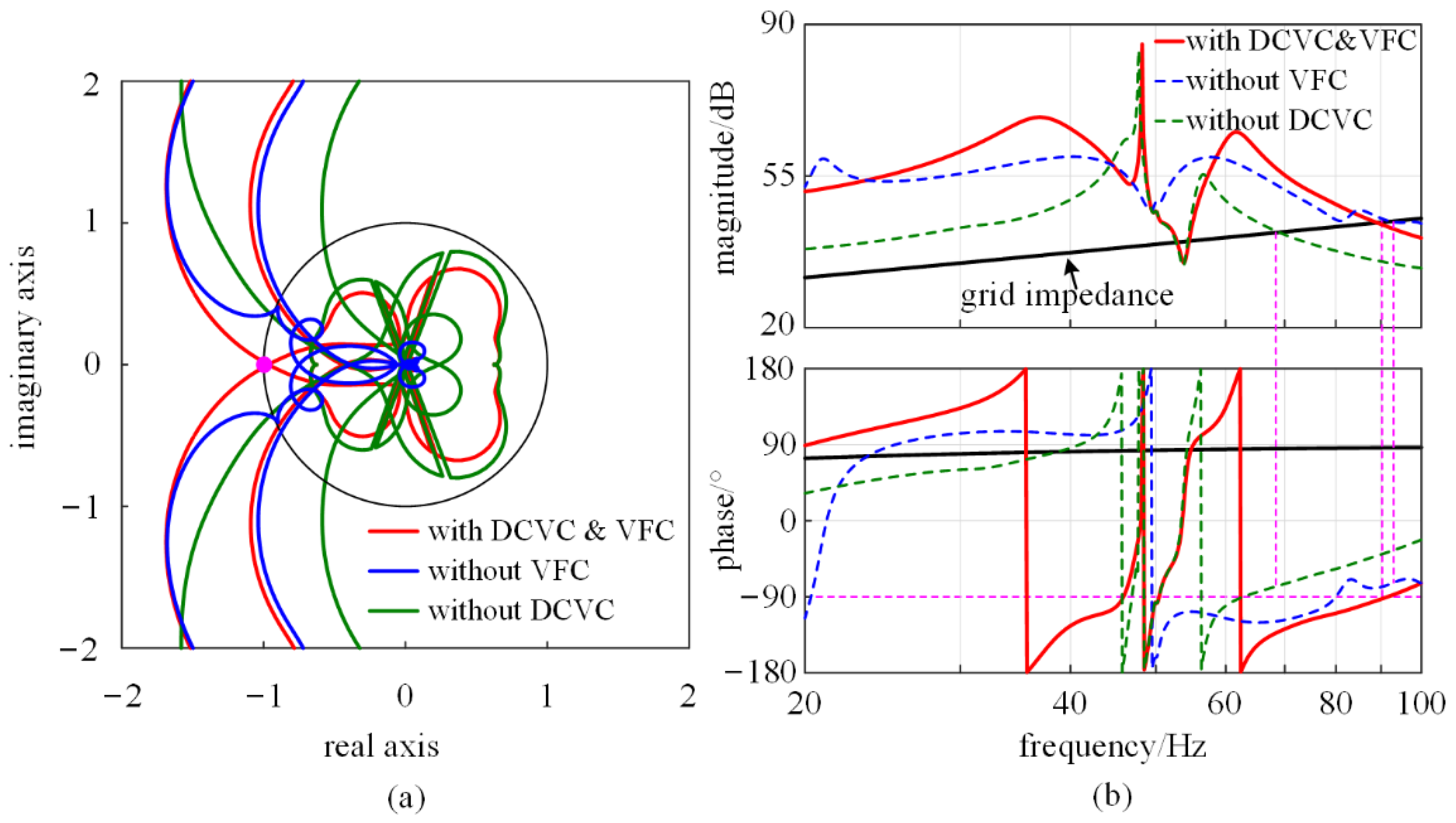
Figure 7a depicts the eigenloci curve of the return ratio matrix ZMMC(s)/Zg(s) of three cases. If the DC voltage control or voltage feedforward control is ignored in the system stability analysis, both trajectories will not enclose the (−1, j 0) point, indicating that the system is stable. However, when both DC voltage control and voltage feedforward control are considered in the stability analysis as an actual control structure, the trajectories will enclose the (−1, j 0) point clockwise, implying instability. The opposite analysis result indicated that both DC voltage control and voltage feedforward control are not negligible for stability analysis.
Figure 7b illustrates the frequency responses of impedance of MMC-HVDC considering DC voltage control and voltage feedforward control ZMMC(s) and Zg(s). The comparison of the impedance that ignores DC voltage control or voltage feedforward control is also shown in Figure 7b. The interaction characteristic of the MMC-HVDC ignoring DC voltage control or voltage feedforward control with grid impedance implies that the system will be stable. However, the MMC-HVDC impedance shows a negative-damping characteristic at the intersection frequency of 90 Hz, which makes the phase margin of the MMC-HVDC integrated system less than 0°. Those impedance responses may result in a resonance of the MMC-HVDC at the intersection frequency when DC voltage control and voltage feedforward control are considered.
A simulation developed in MATLAB/Simulink was used to verify the above analysis results, and the time-domain simulated results are shown in Figure 8. It can be found that there are obvious resonance exits in the injected currents of the MMC-HVDC. The corresponding FFT result of the injected current in Figure 8b confirms the resonance frequency is 90 Hz, which is in agreement with the impedance-based stability analysis.

5. Impedance Optimization Method for MMC-HVDC

From the above analysis, it can be seen that both DC voltage control and voltage feedforward control greatly influence the grid-connected system’s stability. Since the parameters of DC voltage control and voltage feedforward control impact each other, an impedance optimization method based on the stability boundary design is proposed in this section to improve the system stability.

5.1. Stability Boundary for the Control Parameters

According to the above analysis, both DC voltage control and voltage feedforward control have impacts on the MMC-HVDC impedance characteristics and grid-connected system stability in sub-/super-synchronous frequency ranges. The boundary conditions of voltage feedforward control parameters that ensure the grid-connected system stability will be different when the bandwidth of the DC voltage control changes, and vice versa. Therefore, the DC voltage control and voltage feedforward control need to be designed cooperatively. 
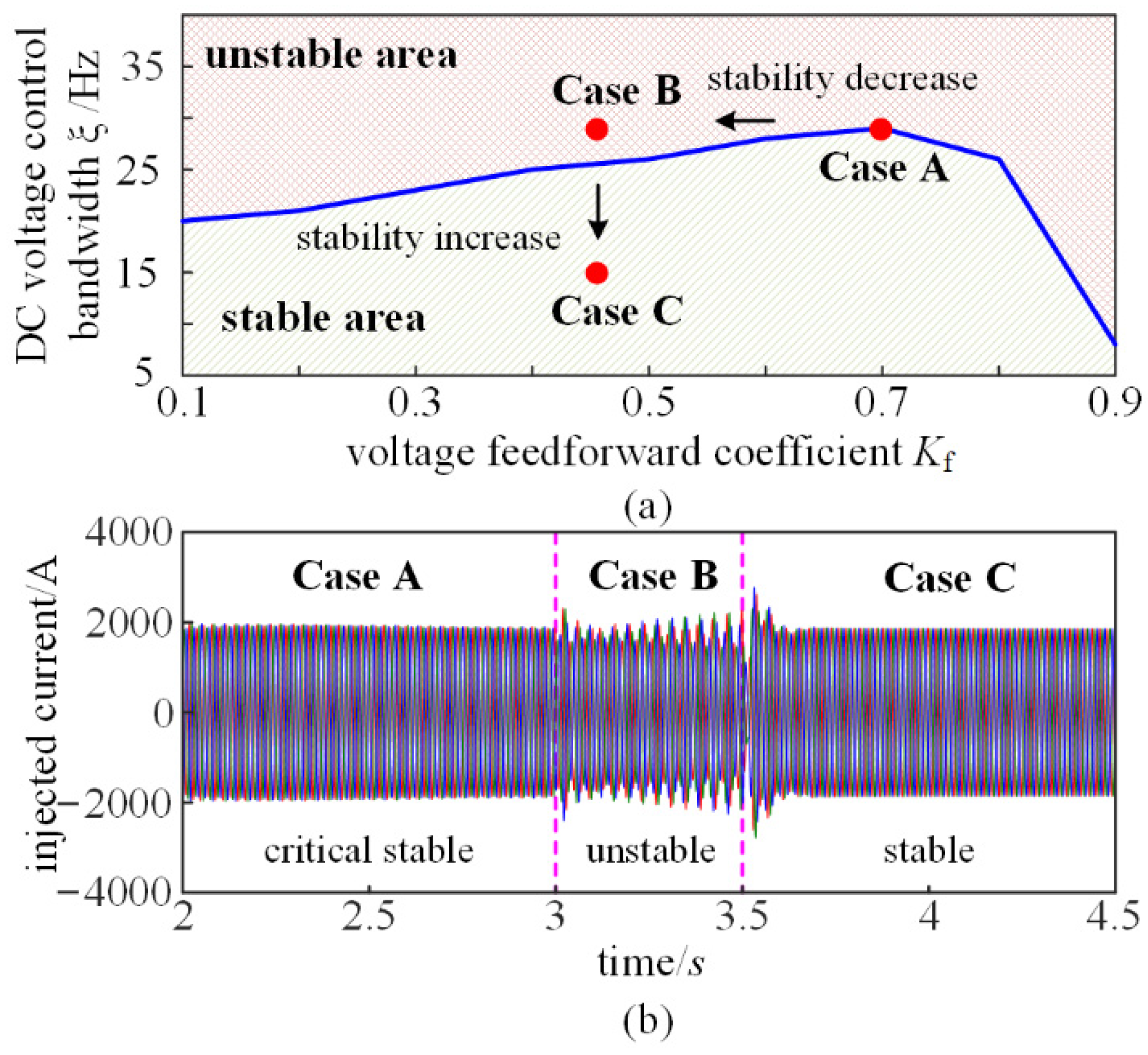
Figure 9a depicts the mapping of the stability margin of MMC-HVDC grid-connected system with different pairs of parameters of DC voltage control and voltage feedforward control. When the parameter combination (Kf, ξ) is located in the stable area (the lower area below the solid blue line), the corresponding stability margin is larger than 0. Otherwise, when the parameter combination (Kf, ξ) is located in the unstable area (the upper area higher than the solid blue line), the corresponding stability margin is less than 0. The solid blue line with zero stability margin represents the stability boundary of two control parameters to ensure the grid-connected system stability; the blue line is defined as ξmax(kf), kf is between Kfmin ~ Kfmax that can ensure the self-stability of MMC-HVDC.
Taking the three cases shown in Figure 9a as an example, Case A is on the blue line (the same case used in Ch. 4), whose DC voltage control bandwidth is 29 Hz and the voltage feedforward coefficient is 0.7, indicating the system is critical stable. If the system changes from Case A to Case B, i.e., the voltage feedforward coefficient decreases from 0.7 to 0.45, then the operating point changes from a stable area to an unstable area. If the system changes from Case B to Case C, i.e., the bandwidth of DC voltage control decreases from 29 Hz to 13 Hz, then the operating point changes from an unstable area to a stable area again.
The injected current waveforms of MMC-HVDC are shown in Figure 9b. From 2 s to 3 s, the bandwidth of DC voltage control is 29 Hz, and the voltage feedforward coefficient is 0.7 (Case A). The voltage feedforward coefficient changes from 0.7 to 0.45 at 3 s (Case B), and the bandwidth of DC voltage control decreases from 29 Hz to 13 Hz at 3.5 s (Case C). As is shown, injected currents of MMC-HVDC are critically stable/stable in Case A and Case C, and resonance occurs in case B. The simulation results are consistent with the impedance-based stability analysis.

5.2. Impedance Optimization Method Based on Parameters Stability Boundary

All the parameter combinations (Kf, 
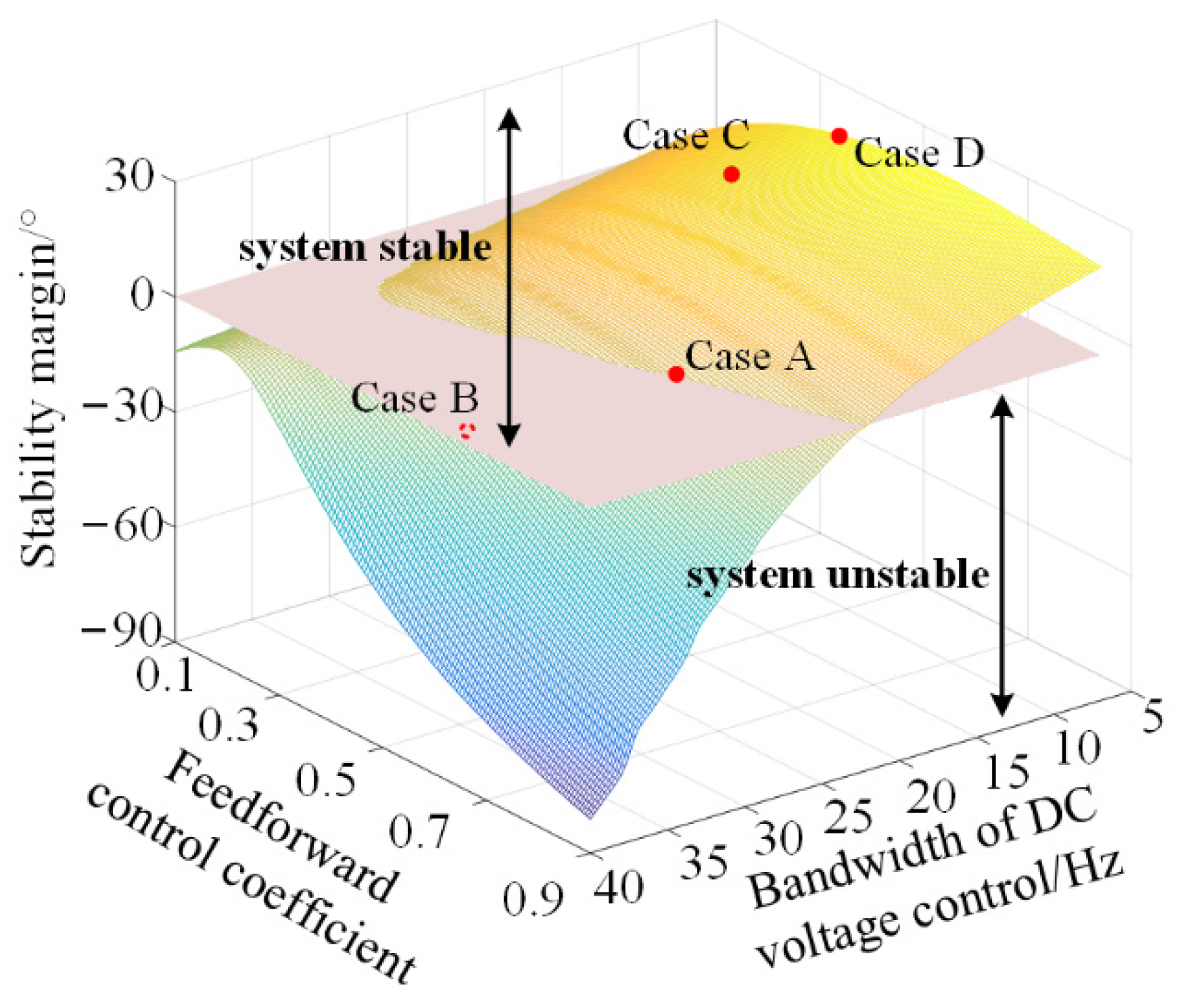
ξ) inside the stability boundary can maintain the MMC-HVDC system stable, but the corresponding phase margin will be different. The impedance optimization method of MMC-HVDC is to maximize the phase margin of the system. The relationship between the parameter combination (Kf, ξ) and system stability margin is illustrated in Figure 10. The (Kf, ξ) that lead to a zero-stability margin will be on the pink plane as Case A. The (Kf, ξ) that lead to a positive stability margin will be above the pink plane as Case C, otherwise, it will be under the pink plane as Case B.
It is difficult to quantify the effect of the parameter combination (Kf, ξ) on the phase margin of the integrated system. Thus, the traversal algorithm is used in this section to calculate every phase margin θs of the MMC-HVDC system under all the (Kf, 
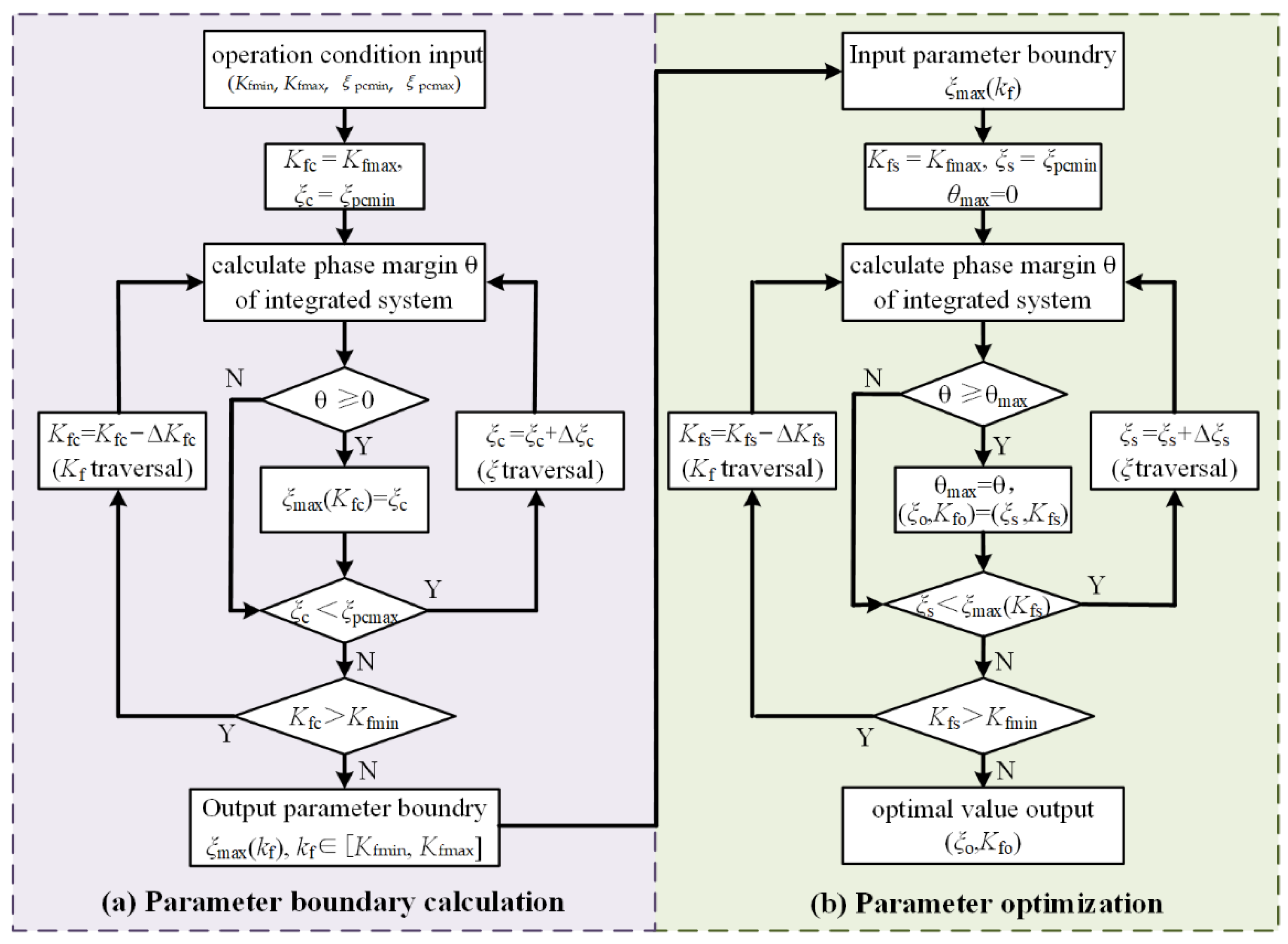
ξ) within the boundary obtained above. Maximizing the phase margin is taken as the aim of impedance optimization. The process of the impedance optimization is shown in Figure 11. The impedance optimization can be divided into the control parameter stability boundary calculation as shown in Figure 12a, and traversal searching of optimized control parameters as shown in Figure 11b.
The process of parameter boundary calculation should be:
Step 1: Input the working conditions of the MMC-HVDC integrated system, including the parameters of the power grid and control parameters and the boundary of parameter combination (Kf, ξ) that can ensure the self-stability of MMC-HVDC denoted as Kfmin ~ Kfmax and ξpcmin ~ ξpcmax.
Step 2: Keep kf as a constant Kfc and traverse all the possible values of bandwidth of DC voltage control ξ within ξpcmin ~ ξpcmax by the step of Δξc and calculate every phase margin under each (Kfc, ξ).
Step 3: Denoted the maximum of ξ that leads to a positive stability margin as ξmax(Kfc) under kf as a constant Kfc.
Step 4: Traversal all the possible value of kf within the Kfmin ~ Kfmax by the step of ΔKfc and repeat steps 2–4.
Step 5: Output stability boundary ξmax(kf), kf ∈ [Kfmin, Kfmax].
The process of parameter optimization should be:
Step 1: Input the working conditions of the MMC-HVDC integrated system as well as the parameter boundary ξmax(kf).
Step 2: Traversal all the possible parameter combination (Kf, ξ) within the ξmax(kf) by the step of ΔKfs and Δξs.
Step 3: Output the maximum of the phase margin and corresponding parameters as the optimal outputs (Kfo, ξo).
In the application shown in Figure 11, the optimal control parameters of (Kfo, ξo) are 5Hz and 0.4, which is shown as Case D, and the maximum phase margin is 26.7°. The system impedance characteristic in Case D (ξo = 5 Hz, Kfo = 0.4), Case A (ξ = 25 Hz, Kf = 0.7), and Case C (ξ = 13 Hz, Kf = 0.45) are compared in Figure 12. It can be observed that both the amplitude intersection frequency of MMC-HVDC and grid impedance in Case C and Case D change from 90 Hz (Case A) to 78 Hz, where the MMC-HVDC impedance characteristics change from negative-damping to positive-damping. The system stability margin increased more in Case D than in Case C. This verifies that the parameters within the boundary can ensure the grid-connected system stability, and the parameters searched by the proposed optimization method can maximize the phase margin of the system.
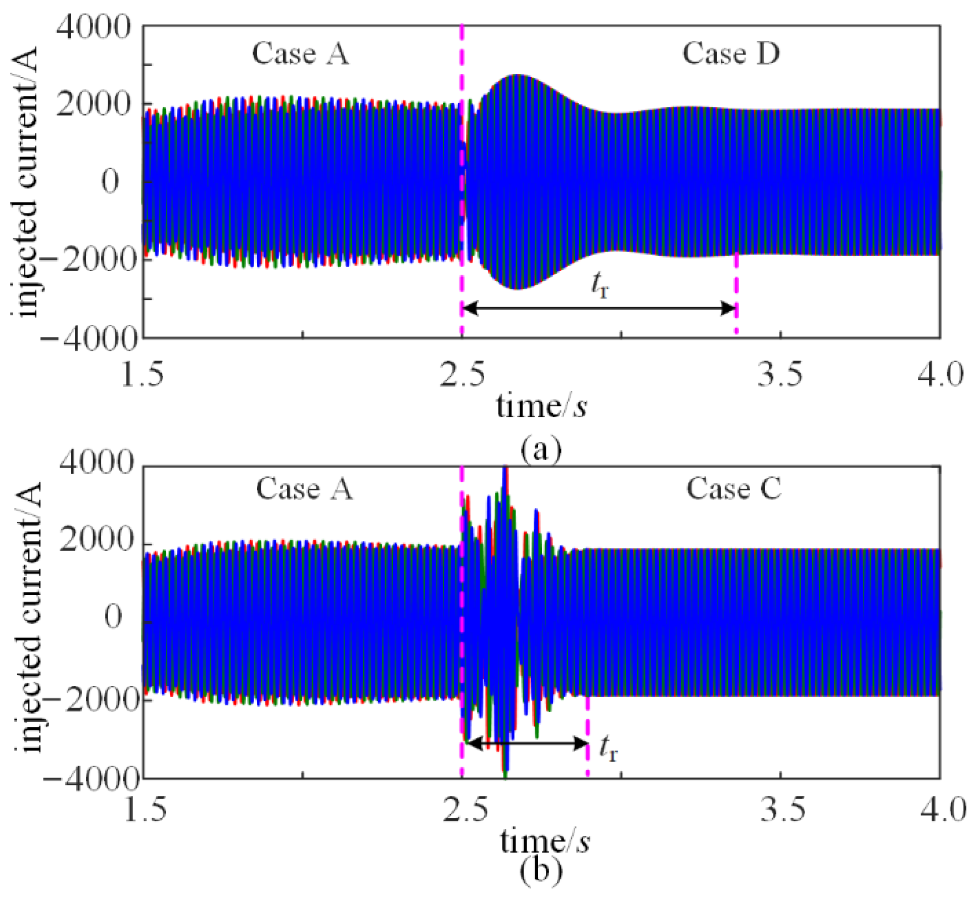
The injected current waveforms of MMC-HVDC system are shown in Figure 13. At the beginning of the simulation, the MMC-HVDC is operated as in Case A. At 2.5 s, the system changes from Case A to Case D (ξ = 5 Hz, Kf = 0.4, obtained by the proposed optimization method above). As is shown in Figure 13a, the injected current of MMC-HVDC contains significant harmonics within 2.5 s and becomes stable after impedance optimization. The THD of the stable current waveforms after optimization is less than 1%. Compared with the optimized control parameter (Case D), Case C of other nonoptimized stability parameters, shown in Figure 13b, has significantly more current harmonics during the switching processing, indicating that Case C is more likely to introduce resonance due to disturbance. Thus, the proposed impedance optimization method can effectively improve the system stability of MMC-HVDC.

6. Conclusions

In this paper, the MMC-HVDC impedance modeling and influence of the control parameter on the impedance characteristics and the stability of the grid integrated system considering both DC voltage control and voltage feedforward control are studied, and the following can be concluded:
(1)
In the multi-terminal flexible direct transmission system, there must be a DC voltage control in the MMC-HVDC converter station to maintain the DC voltage stability. Moreover, the voltage feedforward control cannot be ignored either. An MMC impedance modeling considering DC voltage control and voltage feedforward control is derived by using the multi-harmonic linearization method.
(2)
The DC voltage control and voltage feedforward control have great impacts on the impedance characteristics as well as the system stability analysis. The different control loops of MMC-HVDC interact on the premise of guaranteeing the grid-connected system stability. The boundary condition of MMC-HVDC control parameters is given to guide the design of DC voltage control and voltage feedforward control to ensure the system stability.
(3)
An MMC-HVDC impedance optimization method based on stability boundary is proposed. The optimal stability margin is achieved by searching the control parameters within the stability boundary. The impedance optimization method of MMC-HVDC can ensure the stability of the integrated system and maximize the phase margin of the system.

Author Contributions

Conceptualization, T.H. and X.C.; methodology, T.H. and X.C.; software, T.H.; validation, T.H.; formal analysis, T.H.; investigation, T.H.; resources, X.C.; data curation, T.H.; writing—original draft preparation, T.H.; writing—review and editing, X.C.; visualization, T.H.; supervision, X.C.; project administration, X.C.; funding acquisition, X.C. All authors have read and agreed to the published version of the manuscript.

Funding

This work was supported by the National Natural Science Foundation of China (52277186).

Data Availability Statement

The data presented in this study are available on request from the corresponding author.

Conflicts of Interest

The authors declare no conflict of interest.

Appendix A

The nonzero elements in T1 ~ T5 are expressed as (A1):
T 1 ( 2 , 1 ) = 1 2 V 1 p , T 1 ( 2 , 3 ) = 1 2 V 1 n T 2 ( 2 , 1 ) = 1 2 I 1 p , T 2 ( 2 , 3 ) = 1 2 I 1 n T 3 ( 2 , 1 ) = ( s j ω 1 ) L I 1 p 2 , T 3 ( 2 , 2 ) = ( s j ω 1 ) L I d c , T 3 ( 2 , 3 ) = ( s j ω 1 ) L I 1 n 2 , T 3 ( 2 , 4 ) = ( s j ω 1 ) L I 2 n 2 T 4 ( 2 , 1 ) = ( s j ω 1 ) C m V C 1 p 2 , T 4 ( 2 , 2 ) = ( s j ω 1 ) C m V C d c , T 4 ( 2 , 3 ) = ( s j ω 1 ) C m V C 1 n 2 , T 4 ( 2 , 4 ) = ( s j ω 1 ) C m V C 2 n 2 T 5 ( 2 , 2 ) = 3
where V1p and V1n represent the positive and negative Fourier coefficients of the output voltage at the fundamental frequency (f1). I1p, I1n, I2p, and I2n represent the positive and negative Fourier coefficients of the phase current at f1 and two times of f1. VCdc, VC1p, VC1n, and VC2n represent the positive and negative Fourier coefficients of the equivalent capacitive voltage at dc, f1, and two times of f1.
The nonzero elements in Q1 are expressed as (A2):
Q 1 ( 2 , 4 ) = 2 H i ( s j ω 1 ) + j 2 K i , Q 1 ( 4 , 4 ) = 2 H i ( s j ω 1 ) j 2 K i
where Hi(s-−1) represent PI regulators of phase current control and Ki represents dq-frame decoupling coefficient of phase current control.
The nonzero elements in Q2 are expressed as (A3):
Q 2 ( 2 , 2 ) = G θ ( s j ω 1 ) ( 2 ( H i ( s j ω 1 ) j K i ) I ˙ 1 n M ˙ 1 n ) e j φ 1 , Q 2 ( 2 , 4 ) = G θ ( s j ω 1 ) ( 2 ( H i ( s j ω 1 ) + j K i ) I ˙ 1 n + M ˙ 1 n ) e j φ 1 , Q 2 ( 4 , 2 ) = G θ ( s j ω 1 ) ( 2 ( H i ( s j ω 1 ) + j K i ) I ˙ 1 p + M ˙ 1 p ) e j φ , Q 2 ( 4 , 4 ) = G θ ( s j ω 1 ) ( 2 ( H i ( s j ω 1 ) + j K i ) I ˙ 1 p M ˙ 1 p ) e j φ 1
where Gθ(s-−1) = Tθ(s)/(1 + VsTθ(s)) and Tθ(s) = Hθ(s)/s. M1p and M1n represent the positive and negative Fourier coefficients of the modulated signal at f1, φ1 is the phase of Vs.
The nonzero elements in Q3 are expressed as (A4):
Q 3 ( 2 , 3 ) = 0.5 H d ( s j ω 1 ) H i ( s j ω 1 ) e j φ 1 , Q 3 ( 4 , 3 ) = 0.5 H d ( s j ω 1 ) H i ( s j ω 1 ) e j φ 1
where Hd(s1) and Hi(s1) represent PI regulators of DC voltage control and phase current control.
The nonzero elements in Qv2 are expressed as (A5):
Q v 2 ( 2 , 2 ) = 0.5 G θ ( s j ω 1 ) G f ( s j ω 1 ) V s + H f ( s j ω 1 ) , Q v 2 ( 2 , 4 ) = 0.5 G θ ( s j ω 1 ) G f ( s j ω 1 ) V s e j φ 1 , Q v 2 ( 4 , 2 ) = 0.5 G θ ( s j ω 1 ) G f ( s j ω 1 ) V s e j φ , Q v 2 ( 4 , 4 ) = 0.5 G θ ( s j ω 1 ) G f ( s j ω 1 ) V s + H f ( s j ω 1 )
where Hf(s) represents the voltage feedforward controller.

References

  1. Sun, J.; Li, M.; Zhang, Z.; Xu, T.; He, J.; Wang, H.; Li, G.; Rensselaer Polytechnic Institute; State Grid Corporation of China; China Electric Power Research Institute. Renewable energy transmission by HVDC across the continent: System challenges and opportunities. CSEE J. Power Energy Syst. 2017, 3, 353–364. [Google Scholar] [CrossRef]
  2. Blaabjerg, F.; Yang, Y.; Yang, D.; Wang, X. Distributed Power-Generation Systems and Protection. Proc. IEEE 2017, 105, 1311–1331. [Google Scholar] [CrossRef] [Green Version]
  3. Xiong, L.; Liu, X.; Liu, Y.; Zhuo, F. Modeling and Stability Issues of Voltage-source Converter Dominated Power Systems: A Review. CSEE J. Power Energy Syst. 2022, 8, 1530–1549. [Google Scholar] [CrossRef]
  4. Shair, J.; Xie, X.; Wang, L.; Liu, W.; He, J.; Liu, H. Overview of Emerging Sub-synchronous Oscillations in Practical Wind Power Systems. Renew. Sustain. Energy Rev. 2019, 99, 159–168. [Google Scholar] [CrossRef]
  5. Xie, X.; Zhang, X.; Liu, H.; Liu, H.; Li, Y.; Zhang, C. Characteristic Analysis of Sub-synchronous Resonance in Practical Wind Farms Connected to Series-Compensated Transmissions. IEEE Trans. Energy Convers. 2017, 32, 1117–1126. [Google Scholar] [CrossRef]
  6. Zou, C.; Rao, H.; Xu, S.; Li, Y.; Li, W.; Chen, J.; Zhao, X.; Yang, Y.; Lei, B. Analysis of Resonance between a VSC-HVDC Converter and the AC Grid. IEEE Trans. Power Electron. 2018, 33, 10157–10168. [Google Scholar] [CrossRef]
  7. Buchhagen, C.; Rauscher, C.; Menze, A.; Jung, J. BorWin1–First Experiences with Harmonic Interactions in Converter Dominated Grids. In Proceedings of the International ETG Congress 2015, Die Energiewende—Blueprints for the New Energy Age, Bonn, Germany, 17–18 November 2015; pp. 1–7. [Google Scholar]
  8. Saad, H.; Fillion, Y.; Deschanvres, S.; Vernay, Y.; Dennetière, S. On Resonances and Harmonics in HVDC-MMC Station Connected to AC Grid. IEEE Trans. Power Deliv. 2017, 32, 1565–1573. [Google Scholar] [CrossRef]
  9. Sun, J.; Liu, H. Sequence Impedance Modeling of Modular Multilevel Converters. IEEE J. Emerg. Sel. Top. Power Electron. 2017, 5, 1427–1443. [Google Scholar] [CrossRef]
  10. Huang, T.; Chen, X.; Li, G.; He, G. Sequence Impedance Modeling and Frequency Characteristic Analysis of MMC-based HVDC. In Proceedings of the 2019 10th International Conference on Power Electronics and ECCE Asia (ICPE 2019—ECCE Asia), Busan, Republic of Korea, 27–30 May 2019; pp. 1–8. [Google Scholar]
  11. Huang, T.; Chen, X.; Li, Z. Impacts of Coupling Effects on Stability Analysis of PMSG-based Wind Farm Integration through MMC-HVDC. In Proceedings of the 2020 IEEE 9th International Power Electronics and Motion Control Conference (IPEMC2020-ECCE Asia), Nanjing, China, 9 March 2020; pp. 1918–1923. [Google Scholar]
  12. Huang, T.; Yang, F.; Zhang, D.; Chen, X. High-Frequency Stability Analysis and Impedance Optimization for an MMC-HVDC Integrated System Considering Delay Effects. IEEE J. Emerg. Sel. Top. Circuits Syst. 2022, 12, 59–72. [Google Scholar] [CrossRef]
  13. Wu, H.; Wang, X. Passivity-Based Dual-Loop Vector Voltage and Current Control for Grid-Forming VSCs. IEEE Trans. Power Electron. 2021, 36, 8647–8652. [Google Scholar] [CrossRef]
  14. Wu, H.; Wang, X. Dynamic Impact of Zero-Sequence Circulating Current on Modular Multilevel Converters: Complex-Valued AC Impedance Modeling and Analysis. IEEE J. Emerg. Sel. Top. Power Electron. 2020, 8, 1947–1963. [Google Scholar] [CrossRef]
  15. Lyu, J.; Cai, X.; Molinas, M. Optimal Design of Controller Parameters for Improving the Stability of MMC-HVDC for Wind Farm Integration. IEEE J. Emerg. Sel. Top. Power Electron. 2018, 6, 40–53. [Google Scholar] [CrossRef] [Green Version]
  16. Zhang, Y.; Yang, Y.; Chen, X.; Gong, C. Intelligent Parameter Design-Based Impedance Optimization of STATCOM to Mitigate Resonance in Wind Farms. IEEE J. Emerg. Sel. Top. Power Electron. 2021, 9, 3201–3215. [Google Scholar] [CrossRef]
  17. Zhu, J.; Hu, J.; Wang, S.; Wan, M. Small-Signal Modeling and Analysis of MMC Under Unbalanced Grid Conditions Based on Linear Time-Periodic (LTP) Method. IEEE Trans. Power Deliv. 2021, 36, 205–214. [Google Scholar] [CrossRef]
  18. Liu, H.; Xie, X. Impedance Network Modeling and Quantitative Stability Analysis of Sub-/Super-Synchronous Oscillations for Large-Scale Wind Power Systems. IEEE Access 2018, 6, 34431–34438. [Google Scholar] [CrossRef]
  19. Adams, J.; Carter, C.; Huang, S. ERCOT experience with Sub-synchronous Control Interaction and proposed remediation. PES TD 2012, 2012, 1–5. [Google Scholar]
  20. Cheng, Y.; Huang, S.-H.; Rose, J.; Pappu, V.A.; Conto, J. ERCOT Sub-synchronous Resonance Topology and Frequency Scan tool Development. In Proceedings of the 2016 IEEE Power and Energy Society General Meeting (PESGM), Boston, MA, USA, 17–21 July 2016; pp. 1–5. [Google Scholar]
  21. Adams, J.; Pappu, V.A.; Dixit, A. Ercot Experience Screening for Sub-synchronous Control Interaction in the Vicinity of Series Capacitor Banks. In Proceedings of the 2012 IEEE Power and Energy Society General Meeting, San Diego, CA, USA, 22–26 July 2012; pp. 1–5. [Google Scholar]
  22. Liu, H.; Xie, X.; Zhang, C.; Li, Y.; Liu, H.; Hu, Y. Quantitative SSR Analysis of Series-compensated DFIG-Based Wind Farms Using Aggregated RLC Circuit Model. IEEE Trans. Power Syst. 2017, 32, 474–483. [Google Scholar] [CrossRef]
  23. Liu, H.; Xie, X.; Liu, W. An Oscillatory Stability Criterion Based on the Unified dq -Frame Impedance Network Model for Power Systems with High-Penetration Renewables. IEEE Trans. Power Syst. 2018, 33, 3472–3485. [Google Scholar] [CrossRef]
Figure 1. Power stage circuit and control diagram of MMC-HVDC considering DC voltage control and voltage feedforward control.
Energies 15 09649 g001
Figure 2. Frequency responses of ZMMC(s).
Energies 15 09649 g002
Figure 3. Impacts of DC voltage controller on MMC-HVDC impedance characteristic. (a) impedance magnitude sensitivity; (b) impedance phase sensitivity.
Energies 15 09649 g003
Figure 4. Impacts of DC voltage controller on MMC-HVDC impedance characteristic (DCVC stands for DC voltage control). (a) comparison of MMC-HVDC impedance characteristic w/wo DC voltage control. (b) impacts of DC voltage control parameters on MMC-HVDC impedance characteristic.
Energies 15 09649 g004
Figure 5. Impacts of voltage feedforward control on admittance characteristics of MMC-HVDC (VFC stands for voltage feedforward control). (a) comparison of MMC-HVDC impedance characteristic w/wo voltage feedforward control. (b) impacts of voltage feedforward control parameters on MMC-HVDC impedance characteristic.
Energies 15 09649 g005
Figure 6. Block diagram of the MMC-HVDC integrated system.
Energies 15 09649 g006
Figure 7. (a) Comparison of eigenloci curve of return ratio matrix ZMMC(s)/Zg(s) w\o DCVC and VFC; (b) Impedance responses of Zg(s) and ZMMC(s) w\o DCVC and VFC.
Energies 15 09649 g007
Figure 8. Simulation results of the MMC-HVDC integrated system: (a) waveform of injected currents; (b) corresponding FFT results of injected currents.
Energies 15 09649 g008
Figure 9. (a) The curve of DC voltage controller bandwidth changing with voltage feedforward coefficient; (b) Waveform of injected current under different voltage feedforward coefficient and DC voltage controller bandwidths.
Energies 15 09649 g009
Figure 10. Impacts of voltage feedforward control coefficient and DC voltage controller bandwidth on stability margin of system.
Energies 15 09649 g010
Figure 11. The flow chart of the impedance optimization (a) the calculation process of parameter boundary; (b) the process of parameter optimization.
Energies 15 09649 g011
Figure 12. Impedance characteristics of the MMC-HVDC system before and after optimization.
Energies 15 09649 g012
Figure 13. (a) Waveform of injected current of the MMC-HVDC integrated system from Case A to Case D. (b) Waveform of injected current of the MMC-HVDC integrated system from Case A to Case C.
Energies 15 09649 g013
Table 1. Parameters of MMC-HVDC in simulation.
ParametersValueParametersValue
Rated power255 MWHd(s)0.021 + 1.743/s
Output L-L voltage375 kVHi(s)7.169 × 10⁻⁵ + 0.024/s
DC-side voltage±350 kVHc(s)6.089 × 10⁻⁵ + 0.024/s
Number of submodules per arm500Hθ(s)4.961 × 10⁻⁵ + 1.062 × 10⁻³/s
Arm inductance L100 mHHf(s)0.7 × 200π/(200π + s)
Module capacitance Cm13.6 mFSimulation step4 µs
Publisher’s Note: MDPI stays neutral with regard to jurisdictional claims in published maps and institutional affiliations.

