
Research on Vibration Characteristics of an Underground Powerhouse of Large Pumped-Storage Power Station


Abstract
1. Introduction
2. Analysis of Vibration Source Characteristics of Underground Powerhouse
2.1. Vibration Source Analysis
2.2. Research on the Characteristics of Vibration Source in Plant Area
2.2.1. Vibration Caused by Vortex Swing and Cavitation in the Draft Tube
- (1)
- Vibration caused by low-frequency vortex swing of draft tube
- nH—unit rated speed, r/min;
- μs—Turbines with relatively high speed generally take μs = 0.03~0.4.
- (2)
- Vibration caused by cavitation
2.2.2. Hydraulic Impact Pulsation of Runner Blades and Guide Vanes
- Z1, Z2—number of runner blades and water guide blades;
- A—the greatest common divisor of Z1 and Z2;
- nH—unit rated speed, r/min.
2.2.3. Vibration Caused by Uneven Flow Field in Volute
3. Overview and Finite Element Model of Pumped-storage Power Station
3.1. Overview of Pumped-Storage Power Station
3.2. Structural Material Properties
- (1)
- The influence of damping is not considered;
- (2)
- Surrounding rock pressure is not considered;
- (3)
- It is considered that the elastic modulus of the surrounding rock is approximately equal to the deformation modulus;
- (4)
- Steel, concrete, and surrounding rock are all regarded as isotropic materials.
3.3. Structural Finite Element Model
4. Modal Analysis of Underground Powerhouse Structure
5. Analysis of Steady-State Response Characteristics of Powerhouse Structure
5.1. Steady-State Process Calculation Principle
5.2. Steady-State Calculation Conditions and Loads
- (1)
- Model 1: Only the powerhouse structure model is established, without considering the effect of surrounding rock, fixed constraints are taken on the upstream and downstream surfaces and bottom, and normal constraints are taken on the downstream surface of the draft tube.
- (2)
- Model 2: Establish the plant structure and surrounding rock model, and establish binding constraints for the boundary nodes of the plant side wall and the surrounding rock to deform together. The deformation modulus of the surrounding rock is selected according to the type II surrounding rock, and the deformation modulus is 4.0 × 10⁴ Mpa, and the Poisson’s ratio is 0.23. The upstream and downstream surfaces and sides of the surrounding rock are constrained by the normal direction, and the bottom is fixed.
- (3)
- Model 3: Establish the plant structure and surrounding rock model, and establish binding constraints for the boundary nodes of the plant side walls to deform together. The deformation modulus of the surrounding rock is selected according to the type III surrounding rock, and the deformation modulus is 3.0 × 10⁴ MPa, and Poisson’s ratio is 0.28. The upstream and downstream surfaces and sides of the surrounding rock are constrained by the normal direction, and the bottom is fixed.
- (4)
- Model 4: Establish the plant structure and surrounding rock model, and establish binding constraints for the boundary nodes of the plant side walls to deform together. The rock deformation modulus is selected according to Class II surrounding rock, and the deformation modulus is 4.0 × 10⁴ MPa, and Poisson’s ratio is 0.23. The upstream and downstream surfaces, sides and bottom of the surrounding rock are fully fixed.
- (1)
- Vertical dynamic load: including generator rotor, turbine runner, axial water thrust, etc.;
- (2)
- Tangential dynamic load: normal torque, two-phase short-circuit torque and out-of-step torque;
- (3)
- Radial dynamic load: When the generator is running, it is caused by magnetic and mechanical imbalance, a short circuit of half of the magnetic poles, and temperature change.
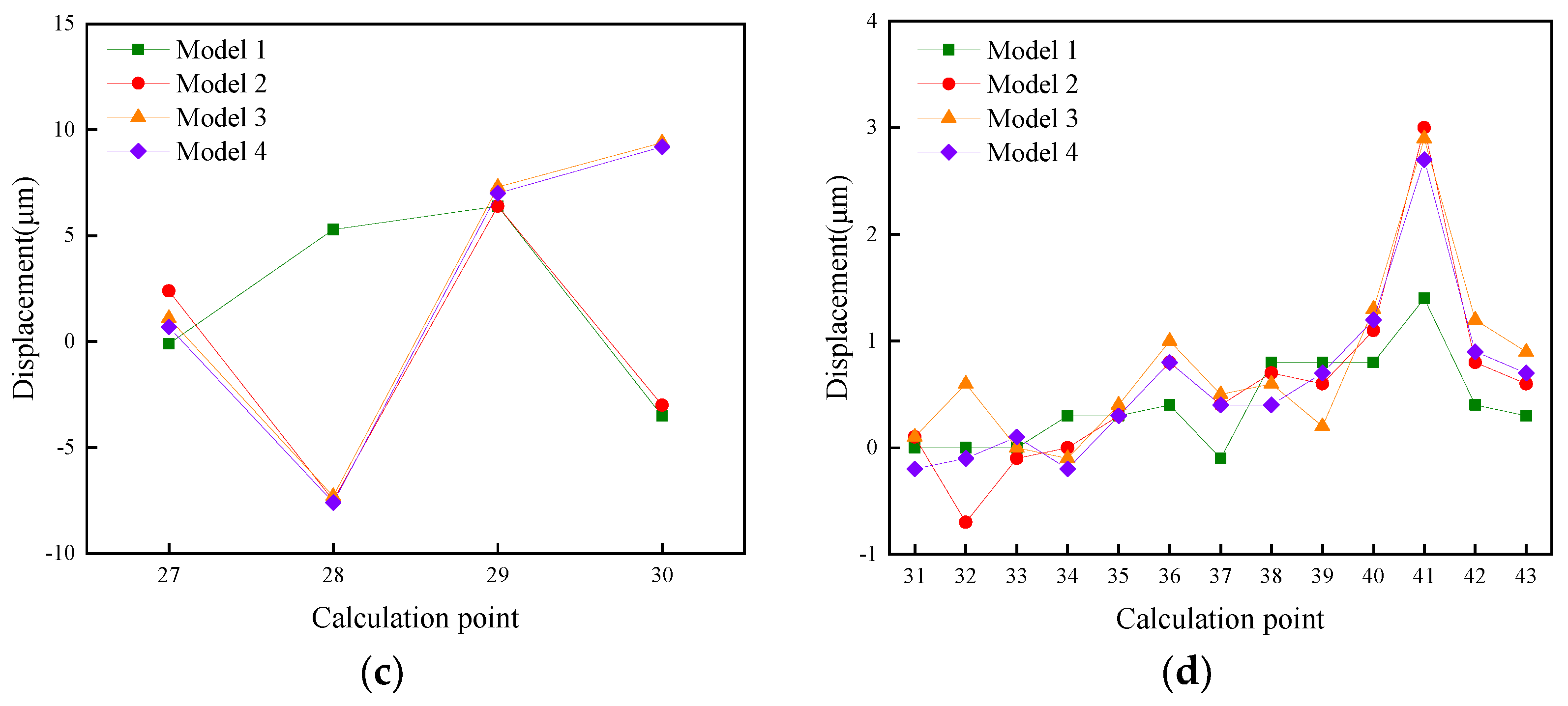
5.3. Calculation Result Analysis of Steady State Process
6. Conclusions
- (1)
- The fundamental frequency of the plant structure and the excitation frequency of the main vibration source are greatly staggered, and resonance will not be induced. Moreover, the mode shape of each order of the plant structure does not change much, mainly manifested as the vibration of the beam-system structure. This is because the stiffness of the beam-system components is much smaller than that of the wind cover, machine pier, and mass concrete around the volute.
- (2)
- According to the calculation results of the dynamic response of the plant in the steady-state process of the unit, the maximum vibration displacement of each calculation point of the plant structure meets the design requirements. The calculation results also reflect the distribution law of the larger vibration displacement positions of the plant structure. It can provide a theoretical reference for the layout of measuring points for plant safety monitoring, and has guiding significance for the anti-vibration and vibration-reduction design of underground plant structures of pumped-storage power stations.
- (3)
- Considering the influence of different connection forms between the upstream and downstream side walls and surrounding rocks on the dynamic response of the factory building structure, four kinds of factory-building-structure models were established. The calculation results of this project show that the maximum displacement of the factory building structure in all directions meets the design requirements. In addition, the distribution law of the large vibration-displacement position of the plant structure is revealed, which can provide a theoretical reference for the arrangement of measuring points for plant safety monitoring.
Author Contributions
Funding
Conflicts of Interest
References
- Lian, J.; Zhang, Y.; Ma, C.; Yang, Y.; Chaima, E. A review on recent sizing methodologies of hybrid renewable energy systems. Energy Convers. Manag. 2019, 199, 112027. [Google Scholar] [CrossRef]
- Mahlia, T.M.I.; Saktisandan, T.J.; Jannifar, A.; Hasan, M.H.; Matseelar, H.S.C. A review of available methods and development on energy storage; technology update. Renew. Sustain. Energy Rev. 2014, 33, 532–545. [Google Scholar] [CrossRef]
- Hemmati, R.; Saboori, H. Emergence of hybrid energy storage systems in renewable energy and transport applications—A review. Renew. Sustain. Energy Rev. 2016, 65, 11–23. [Google Scholar] [CrossRef]
- Koohi-Fayegh, S.; Rosen, M.A. A review of energy storage types, applications and recent developments. J. Energy Storage 2020, 27, 101047. [Google Scholar] [CrossRef]
- Koohi-Kamali, S.; Tyagi, V.V.; Rahim, N.A.; Panwar, N.L.; Mokhlis, H. Emergence of energy storage technologies as the solution for reliable operation of smart power systems: A review. Renew. Sustain. Energy Rev. 2013, 25, 135–165. [Google Scholar] [CrossRef]
- Zhang, H.; Baeyens, J.; Caceres, G.; Degreve, J.; Lv, Y. Thermal energy storage: Recent developments and practical aspects. Prog. Energy Combust. Sci. 2016, 53, 1–40. [Google Scholar] [CrossRef]
- Zhang, H.; Huys, K.; Baeyens, J.; Degreve, J.; Kong, W.; Lv, Y. Thermochemical Energy Storage for Power Generation on Demand. Energy Technol. 2016, 4, 341–352. [Google Scholar] [CrossRef]
- Fernandes, D.; Pitie, F.; Caceres, G.; Baeyens, J. Thermal energy storage: “How previous findings determine current research priorities”. Energy 2012, 39, 246–257. [Google Scholar] [CrossRef]
- Suberu, M.Y.; Mustafa, M.W.; Bashir, N. Energy storage systems for renewable energy power sector integration and mitigation of intermittency. Renew. Sustain. Energy Rev. 2014, 35, 499–514. [Google Scholar] [CrossRef]
- Groppi, D.; Pfeifer, A.; Garcia, D.A.; Krajac, G.; Duic, N. A review on energy storage and demand side management solutions in smart energy islands. Renew. Sustain. Energy Rev. 2021, 135, 110183. [Google Scholar] [CrossRef]
- Wang, X.; Yu, J. The operation strategy and its benefit assessment of the distributed pumped storage system. Power Syst. Prot. Control. 2012, 40, 129–137+142. [Google Scholar]
- Rehman, S.; Al-Hadhrami, L.M.; Alam, M.M. Pumped hydro energy storage system: A technological review. Renew. Sustain. Energy Rev. 2015, 44, 586–598. [Google Scholar] [CrossRef]
- Mansoor, S.P.; Munoz-Hernandez, G.A. Development of gain scheduling scheme for pumped storage plant. In Proceedings of the 9th IASTED International Conference on Intelligent Systems and Control, Honolulu, HI, USA, 14–16 August 2006; p. 13. [Google Scholar]
- Ramos, H.M.; Dadfar, A.; Besharat, M.; Adeyeye, K. Inline Pumped Storage Hydropower towards Smart and Flexible Energy Recovery in Water Networks. Water 2020, 12, 2224. [Google Scholar] [CrossRef]
- Wang, H.; Mao, L.; Lian, J. Structural vibration prediction for a hydropower house based on RVM method. J. Vib. Shock. 2015, 34, 23–27. [Google Scholar]
- Fitzgerald, N.; Arantegui, R.L.; McKeogh, E.; Leahy, P. A GIS-based model to calculate the potential for transforming conventional hydropower schemes and non-hydro reservoirs to pumped hydropower schemes. Energy 2012, 41, 483–490. [Google Scholar] [CrossRef]
- Valavi, M.; Nysveen, A. Variable-Speed Operation of Hydropower Plants. IEEE Ind. Appl. Mag. 2018, 24, 18–27. [Google Scholar] [CrossRef]
- Kuiwei, Z.H.U. Summarization of safety monitoring on underground works of Baishan Pumped Storage Hydropower Station. Water Resour. Hydropower Eng. 2008, 39, 59–62. [Google Scholar]
- Li, Y.; Zhu, X. Measurement and control of vibration from blasting construction of rock-bolted crane beam in underground powerhouse of Hongping Pumped Storage Hydropower Station. Water Resour. Hydropower Eng. 2015, 46, 77–79+83. [Google Scholar]
- Chen, J.; Yang, T. Water filling and discharging test for tailrace system of Xianyou Pumped Storage Hydropower Station. Water Resour. Hydropower Eng. 2015, 46, 41–45. [Google Scholar]
- Dechang, X.U.; Jigong, L.I.; Genyi, Z.U. Reservoir operation of Baishan Pumped Storage Hydropower Station during construction period. Water Resour. Hydropower Eng. 2008, 39, 78–80. [Google Scholar]
- Kiene, S.; Linkevics, O. Simplified model for evaluation of hydropower plant conversion into pumped storage hydropower plant. Latv. J. Phys. Tech. Sci. 2021, 58, 108–120. [Google Scholar] [CrossRef]
- Xiaojun, H.; Bingfang, W.; Min, A.I. Analysis on monitoring of underground powerhouse and water conduit system during water filling and storing process at Langyashan Pumped Storage Hydropower Station. Water Resour. Hydropower Eng. 2008, 39, 79–82. [Google Scholar]
- Jia, D.; Cheng, L. Research on Development of Pumped-Storage Hydropower in Northwest of China. Electr. Power 2012, 45, 5–7. [Google Scholar]
- Xiaoxia, C.; Lin, F.; Runbao, Y. Study on vibration of trash-rack for Baishan Pumped Storage Hydropower Station. Water Resour. Hydropower Eng. 2008, 39, 63–66. [Google Scholar]
- Jing, Y.; Kui, W.U. Analysis of the factors that affect the arrangement of powerhouse of pumped storage power station. J. Hydroelectr. Eng. 2009, 28, 114+157–160. [Google Scholar]
- Zhang, H.; Chen, D.; Xu, B.; Patelli, E.; Tolo, S. Dynamic analysis of a pumped-storage hydropower plant with random power load. Mech. Syst. Signal Process. 2018, 100, 524–533. [Google Scholar] [CrossRef]
- Xueyuan, Z.; Enbo, Z. Analysis on dynamic water closing test of butterfly valve for hydro-power unit in Baishan Pumped Storage Hydropower Station. Water Resour. Hydropower Eng. 2008, 39, 39–41. [Google Scholar]
- Zhao, X.; Gao, L. Study on availability of weathered-rock materials for construction of dam for Wendeng Pumped Storage Hydropower Station. Water Resour. Hydropower Eng. 2014, 45, 73–76. [Google Scholar]
- Zhou, H. Method for water filling and discharging test on water delivery system of Pushihe Pumped Storage Hydropower Station. Water Resour. Hydropower Eng. 2015, 46, 86–87+90. [Google Scholar]
- Jijian, L.; Liang, Q.I.N.; Huijing, T.; Wei, Z.; Chenglian, H.E. Vibration analysis of hydropower-house during start-up process. J. Hydroelectr. Eng. 2006, 25, 1–5+15. [Google Scholar]
- Lian, J.; Hu, Z.; Qin, L.; Wang, R. Study on dynamic characteristics of unit supporting structure of underground power-house of large hydropower station. J. Hydroelectr. Eng. 2004, 23, 49–54. [Google Scholar]
- Lian, J.; Qin, L.; Wang, R.; Hu, Z.; Wang, H. Study on the dynamic characteristics of the power house structure of two-row placed units. J. Hydroelectr. Eng. 2004, 23, 55–60. [Google Scholar]
- Cheng, S.; Li, S.; Si, Z.; Bi, C.; Yang, Y.; Chen, Y. Relational grade analysis for influencing factors and the natural vibration frequency of hydropower house. S. N. Water Transf. Water Sci. Technol. 2017, 15, 190–196+203. [Google Scholar]
- Geng, D.; Song, Z.; Su, C. Review on the Impact of Hydraulic Vibration on Hydropower Unit and Hydropower House and Vibration Control. J. Yangtze River Sci. Res. Inst. 2016, 33, 135–139. [Google Scholar]
- Peng, G.; Qin, L.; Wang, Z.; Tian, H.; Luo, Y.; ASME. Structure Vibration of Hydropower House Induced by Francis Turbine Based on CFD. In Proceedings of the ASME Fluids Engineering Division Summer Conference, Jacksonville, FL, USA, 10–14 August 2008; pp. 1173–1178. [Google Scholar]
- NB/T35011-2016; People’s Republic of China Energy Industry Standards: Design Code for Powerhouses of Hydropower Stations. Chinese Standard: Beijing, China, 5 December 2016.
- Yunhe, L.I.U.; Xingjun, S.; Shouyi, L.I. Study on dynamic characteristics of overflow hydropower house structure. J. Hydroelectr. Eng. 2007, 26, 39–43. [Google Scholar]
- Zhang, C.; Ma, Z.; Zhou, S.; Zhang, Y. Analysis of fluid-solid interaction vibration characteristics of large-scale hydropower house. J. Hydroelectr. Eng. 2012, 31, 192–197. [Google Scholar]
- Song, Z.; Zhao, E. Analysis on endogenous vibrations of hydropower house on soft foundation. J. Hydroelectr. Eng. 2014, 33, 181–186. [Google Scholar]


| Parameter | Unit | Value |
|---|---|---|
| Rated head | m | 545 |
| Rated output | MW | 350 |
| Rated speed | r/min | 428 |
| Runaway speed | r/min | 620 |
| Number of runner blades | / | 11 |
| Number of movable guide vanes | / | 20 |
| Material | Elastic Modulus (MPa) | Poisson’s Ratio | Density (kg/m3) |
|---|---|---|---|
| C30 | 3.0 × 10⁴ | 0.2 | 2500 |
| steel | 2.1 × 10⁵ | 0.3 | 7800 |
| Type II surrounding rock | 1.5 × 10⁴ | 0.22 | 2700 |
| Class III surrounding rock | 0.8 × 10⁴ | 0.25 | 2600 |
| Conditions | 1 | 2 | 3 | 4 | 5 | 6 |
|---|---|---|---|---|---|---|
| Dynamic modulus of elasticity | 1.0 E | 1.1 E | 1.2 E | 1.3 E | 1.4 E | 1.5 E |
| Step | Frequency/Hz | ||||||
|---|---|---|---|---|---|---|---|
| Condition 1 | Condition 2 | Condition 3 | Condition 4 | Condition 5 | Condition 6 | ||
| 1 | 15.07 | 18.25 | 19.06 | 19.84 | 20.58 | 21.31 | 29.287% |
| 2 | 15.23 | 18.45 | 19.27 | 20.05 | 20.81 | 21.54 | 29.288% |
| 3 | 16.20 | 19.62 | 20.49 | 21.32 | 22.13 | 22.91 | 29.291% |
| 4 | 16.23 | 19.65 | 20.52 | 21.36 | 22.17 | 22.95 | 29.291% |
| 5 | 16.62 | 20.12 | 21.02 | 21.88 | 22.70 | 23.50 | 29.291% |
| 6 | 17.21 | 20.84 | 21.77 | 22.66 | 23.51 | 24.34 | 29.290% |
| 7 | 17.23 | 20.87 | 21.80 | 22.69 | 23.54 | 24.37 | 29.287% |
| 8 | 17.67 | 21.40 | 22.36 | 23.27 | 24.15 | 24.99 | 29.288% |
| 9 | 17.84 | 21.60 | 22.56 | 23.48 | 24.37 | 25.23 | 29.288% |
| 10 | 18.06 | 21.87 | 22.84 | 23.78 | 24.68 | 25.54 | 29.290% |
| fj | fz | ||||||||
|---|---|---|---|---|---|---|---|---|---|
| 1 | 2 | 3 | 4 | 5 | 6 | 7 | 8 | ||
| 0.2~2.9 | 6.4~8.6 | 7.1 | 10.5 | 14.2 | 21.3 | 78.6 | 157.2 | ||
| No. | Value | |(fj − fz)/fj| × 100% | |||||||
| 1 | 15.07 | 5.8 | |||||||
| 2 | 15.23 | 6.8 | |||||||
| 3 | 16.20 | 12.3 | |||||||
| 4 | 16.23 | 12.5 | |||||||
| 5 | 16.62 | 14.6 | |||||||
| 6 | 17.21 | 17.5 | |||||||
| 7 | 17.23 | 17.6 | |||||||
| 8 | 17.67 | 19.6 | |||||||
| 9 | 17.84 | 19.4 | |||||||
| 10 | 18.06 | 17.9 | |||||||
| 11 | 18.37 | 15.9 | |||||||
| 12 | 19.32 | 10.2 | |||||||
| 13 | 22.40 | 4.9 | |||||||
| 14 | 22.67 | 6.0 | |||||||
| 15 | 23.18 | 8.1 | |||||||
| 16 | 23.49 | 9.2 | |||||||
| 17 | 23.61 | 9.8 | |||||||
| 18 | 23.69 | 10.1 | |||||||
| 19 | 24.00 | 11.3 | |||||||
| 20 | 24.23 | 12.1 | |||||||
| Conditions | Frequency (Hz) | Standard Value of Load Amplitude (kN) | ||||||
|---|---|---|---|---|---|---|---|---|
| Stator Foundation | Stator Foundation | Stator Foundation | ||||||
| F1 Vertical | F2 Radial | F3 Tangential | F4 Radial | F5 Tangential | F6 Radial | F7 Tangential | ||
| Normal operation | 7.14 | 241.4 | 120.4 | 542 | 298 | 200 | 10 | 2 |
| Conditions | Point Number | Location |
|---|---|---|
| Generator layer | 4, 5 | Rectangular lifting hole upstream of the floor |
| 6, 7 | Lifting hole of the ball valve on the floor plate of the generator | |
| 8, 9, 10, 11 | Windshield top | |
| 12, 13 | Floor stairwell | |
| Middle layer | 19, 20 | Middle layer ball valve hanging hole |
| 21, 22 | Machine pier top | |
| 27, 28, 29, 30 | Stator foundation |
| Condition | Model | X (Horizontal) | Y (Forward) | Z (Vertical) | |||
|---|---|---|---|---|---|---|---|
| No. | Displacement | No. | Displacement | No. | Displacement | ||
| Steady state process | 1 | 27 | 7.6 | 29 | 6.4 | 29 | −54.2 |
| 2 | 29 | −5.8 | 28 | −7.5 | 29 | −59.3 | |
| 3 | 29 | −6.3 | 30 | 9.4 | 29 | −60.7 | |
| 4 | 29 | −5.6 | 30 | 9.2 | 29 | −58.6 | |
Publisher’s Note: MDPI stays neutral with regard to jurisdictional claims in published maps and institutional affiliations. |
© 2022 by the authors. Licensee MDPI, Basel, Switzerland. This article is an open access article distributed under the terms and conditions of the Creative Commons Attribution (CC BY) license (https://creativecommons.org/licenses/by/4.0/).
Share and Cite
Zhang, L.; Guo, Y.; Wang, H.; Yang, X.; Lian, J. Research on Vibration Characteristics of an Underground Powerhouse of Large Pumped-Storage Power Station. Energies 2022, 15, 9637. https://doi.org/10.3390/en15249637
Zhang L, Guo Y, Wang H, Yang X, Lian J. Research on Vibration Characteristics of an Underground Powerhouse of Large Pumped-Storage Power Station. Energies. 2022; 15(24):9637. https://doi.org/10.3390/en15249637
Chicago/Turabian StyleZhang, Lijuan, Yaohua Guo, Haijun Wang, Xuliang Yang, and Jijian Lian. 2022. "Research on Vibration Characteristics of an Underground Powerhouse of Large Pumped-Storage Power Station" Energies 15, no. 24: 9637. https://doi.org/10.3390/en15249637
APA StyleZhang, L., Guo, Y., Wang, H., Yang, X., & Lian, J. (2022). Research on Vibration Characteristics of an Underground Powerhouse of Large Pumped-Storage Power Station. Energies, 15(24), 9637. https://doi.org/10.3390/en15249637