1. Introduction
In order to address the high maintenance cost of non-electric actuators, more/all-electric aircraft that employ “power by wire” actuators are developed to replace them, and this trend has been rapidly increasing in recent years [
1]. To drive the electric actuators in the aircraft, an efficient and light power converter that can control the currents and voltages very accurately and efficiently should be employed. The GaN semiconductor-based power switch is one of the most promising technologies in electric aircraft application, due to its extremely low switching loss [
2]. By using the GaN power semiconductors, which facilitate the implementation of ultra-high-speed converters, the switching frequency can be increased up to several hundred kHz, which can reduce the converter’s size and weight.
In Airbus A350 and A380, the wing flaps and slats of aircraft are controlled by electromechanical actuators (EMA). The fuel consumption reduction and ease of fault detection are the main advantages of the EMA, compared with the conventional hydraulic system. For the reliable development and investigation of using novel EMAs in the aircraft power network, it is vital to be able to emulate the behaviour of the EMA by using a power converter-based emulator [
3] for all ground testing of all future generation aircrafts.
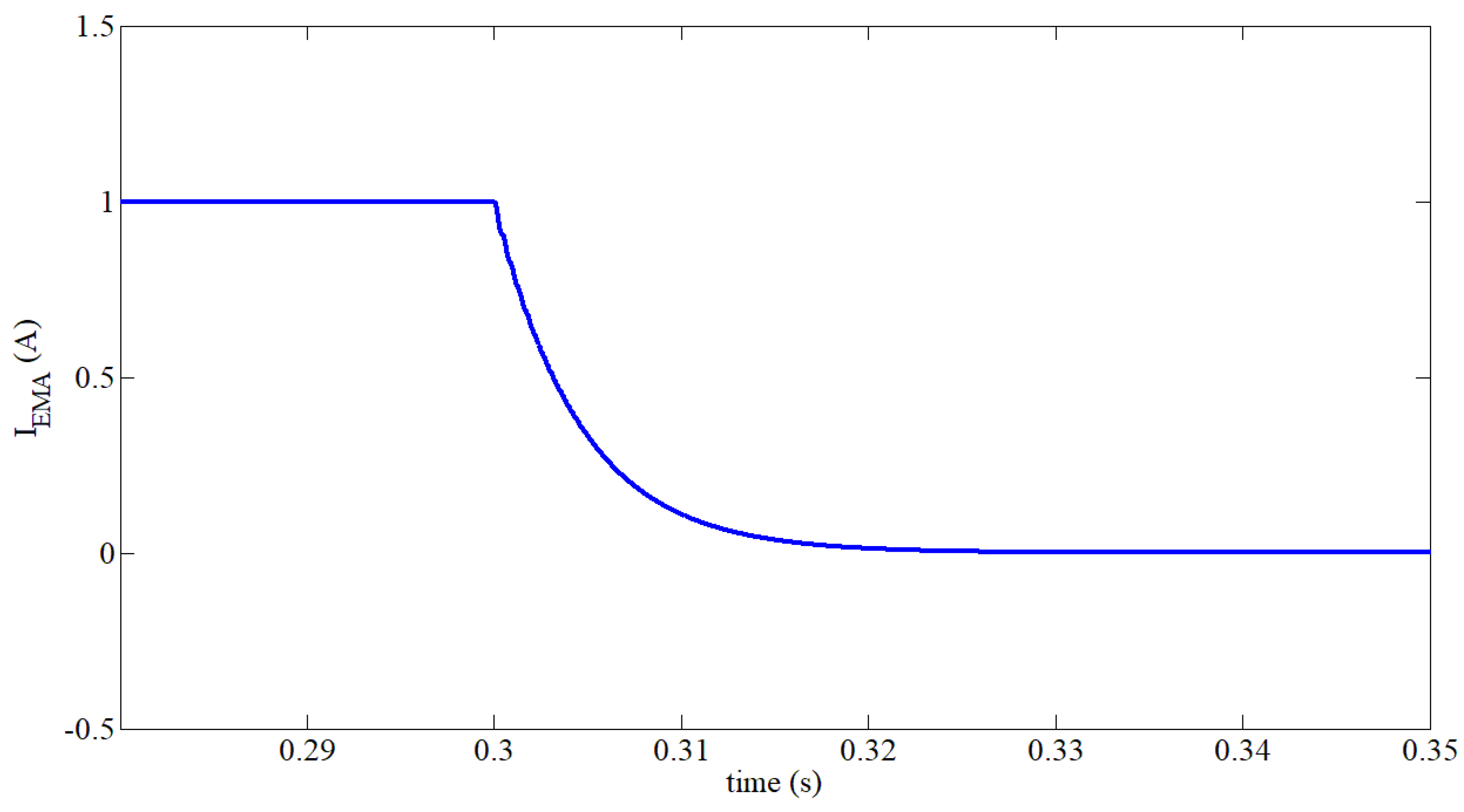
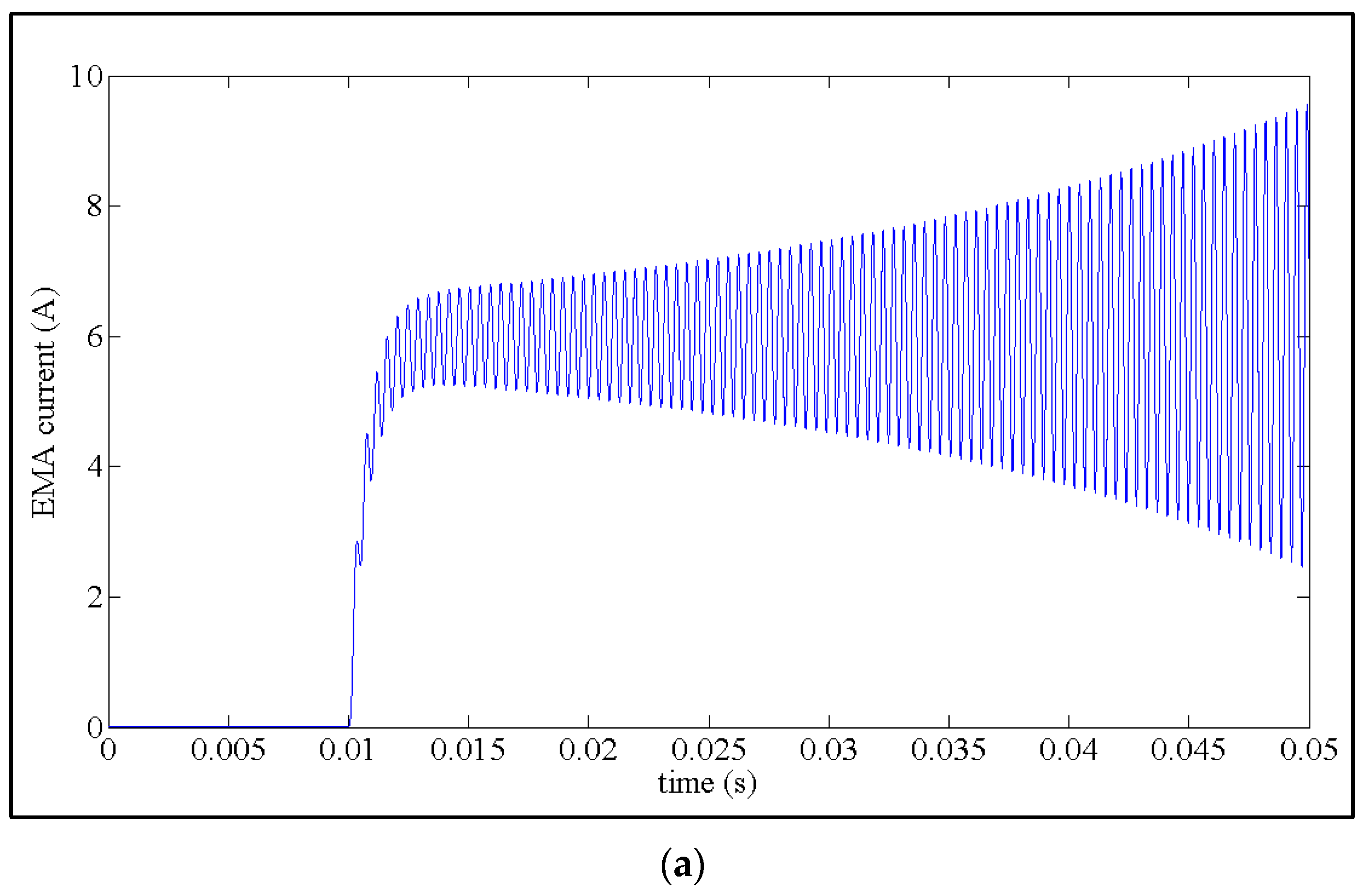
In
Figure 1, a typical profile for the current absorbed from the 270 V DC bus absorbed by a real EMA [
4] and power topology of the developed EMA emulator are illustrated. To emulate the EMA system behaviour, it is necessary to implement a power converter that uses a DC-DC chopper configuration. It should be regulated with a current control loop to track any EMA current profile accurately, similar to the one illustrated in
Figure 1a.
There are two main types of DC-DC converters, buck step-down and boost step-up choppers, that can be employed as an EMA emulator. From the controller design viewpoint, the DC-DC boost converter is a non-minimum phase system [
5]. So, direct output voltage control of the boost DC-DC converter is a challenging task, due to the presence of a right half-plane zero in the system transfer function [
5]. To cope with this problem, indirect output voltage controllers could be employed, which complicates the closed-loop system design and implementation [
6]. Hence, in this paper, a DC-DC buck converter, which is a minimum phase system, will be studied as an EMA emulator, using the asynchronous step-down chopper [
7].
In [
8], the input current control of the DC-DC buck converter was studied for maximum power point tracking of the photovoltaic panels, and a detailed small-signal analysis of the photovoltaic-based battery charger was developed. To improve the accuracy of analysis, parasitic elements of the photovoltaic panel, including the source capacitance/inductance and interconnecting cable dynamics, were modelled. However, the linear controller was developed based on a small-signal approximation. It is well-known that the small-signal approximation can only model the system around the operating point, and it is not valid on the entire range of the model changes. Hence, a linear controller cannot guarantee the stable and robust performance of a system in a wide range of operations.
On the other hand, model-based nonlinear controllers are designed based on the exact model of converter without the help of small-signal approximation. So, the operational domain of nonlinear controllers is not limited to the location of nominal operating point. For example, in [
9], considering the passivity-based control, a nonlinear approach was developed for the closed-loop control of DC-DC converters. As a result, the asymptotic stability of the system can be maintained within the whole of the operating conditions. To decrease the number of required sensors, the state variables of the model were estimated based on the Hamiltonian framework. The asymptotic stability of designed closed-loop system was evaluated and proved using the Lyapunov theory. Due to the employment of an observer, the closed-loop controller can be implemented without input voltage and inductor current sensors. However, the observer’s parameters are tuned by trial and error in [
9]. Hence, the optimum functionality of closed-loop system cannot be guaranteed in [
9].
As another example of a model-based nonlinear control method, the application of adaptive backstepping technique has been reported for closed-loop control of DC-DC converter in the presence of model nonlinearity and uncertainty [
10]. The control law and parameter estimation rules are developed by adding the virtual control inputs successively into the Lyapunov function. Hence, adaptive backstepping can maintain the asymptotic stability of the system in a wide operating range, and its performance does not deteriorate by changes of the controlling gains. However, heavy calculations are needed for the implementation of an adaptive backstepping controller because, for each adaptation rule, a complex differential equation should be solved separately. For this reason, the adaptive backstepping controller is not a very good candidate for the closed-loop control of high-speed power electronics converters.
Moreover, an adaptive extremum-seeking approach for closed-loop control of the DC-DC buck converters was proposed in [
11]. Utilizing a Lyapunov-based adaptive controller guarantees stability and robustness of the closed-loop system in a wide range of operations. For the practical implementation of the adaptive controllers, application of the powerful processors is mandatory for calculation of the control effort and estimation laws. In another word, the adaptive approach is not the first choice for real-time control of the power converters with GaN switches, which may operate at several hundred kHz. So, for closed-loop control of the EMA emulator, a nonlinear controller with a simple control law is a more interesting choice.
Considering the ease of implementation, fast transient response, and robustness in a wide range of operations, the application of sliding mode control (SMC) is a remarkable choice for the closed-loop control of the power converters. So, the SMC of the synchronous buck DC-DC converters is studied in [
12]. To stabilize the switching frequency of the converter, an extra control-loop is needed for the adjustment of the hysteresis band of the SMC. The robustness of the developed controller is investigated at different operating points. However, as the input current of the standard DC-DC buck converter has a pulsating waveform, it cannot be employed for the EMA emulator directly. To smooth out the input current, an LC filter could be inserted between the voltage source and the input port of the buck choppers, as shown in
Figure 1b. However, the existence of the LC filter may result in un-damped oscillations in the closed-loop system, which deteriorates the converter stability [
13].
Briefly, the main challenges of the input current controller design for the EMA emulator can be summarized as follows:
- (a)
Due to the nonlinear model of system, the use of conventional linear controllers is not straightforward. In this paper, although a modified PI-feedforward controller is developed analytically for the EMA emulator, it is seen that the controller cannot stabilize the closed-loop system against model uncertainty, e.g., changes in the input filter parameters.
- (b)
Changes of the operating point in a wide range. Considering the current profile of EMA in
Figure 1a, the closed-loop controller needs to stabilize the system at different operating points. Hence, if the controller is tuned at a specific operating point using a small signal approximation, stability cannot be guaranteed within the whole operating domain.
- (c)
The application of an LC filter for current smoothing at the input port of EMA emulator complicates the controller design since the LC circuit has an inherent tendency to generate oscillation and instability.
To cope with these problems, a fixed-frequency SMC for the input current control of the DC-DC synchronous buck converter is designed in this paper, which can be employed as an EMA emulator. Despite the application of the LC input filter, the stability of the proposed controller is proved considering Lyapunov theory, so it can stabilize the closed-loop system in a wide range of operations. Moreover, a systematic approach is introduced for tuning the developed nonlinear controller and selection of the SMC’s gains.
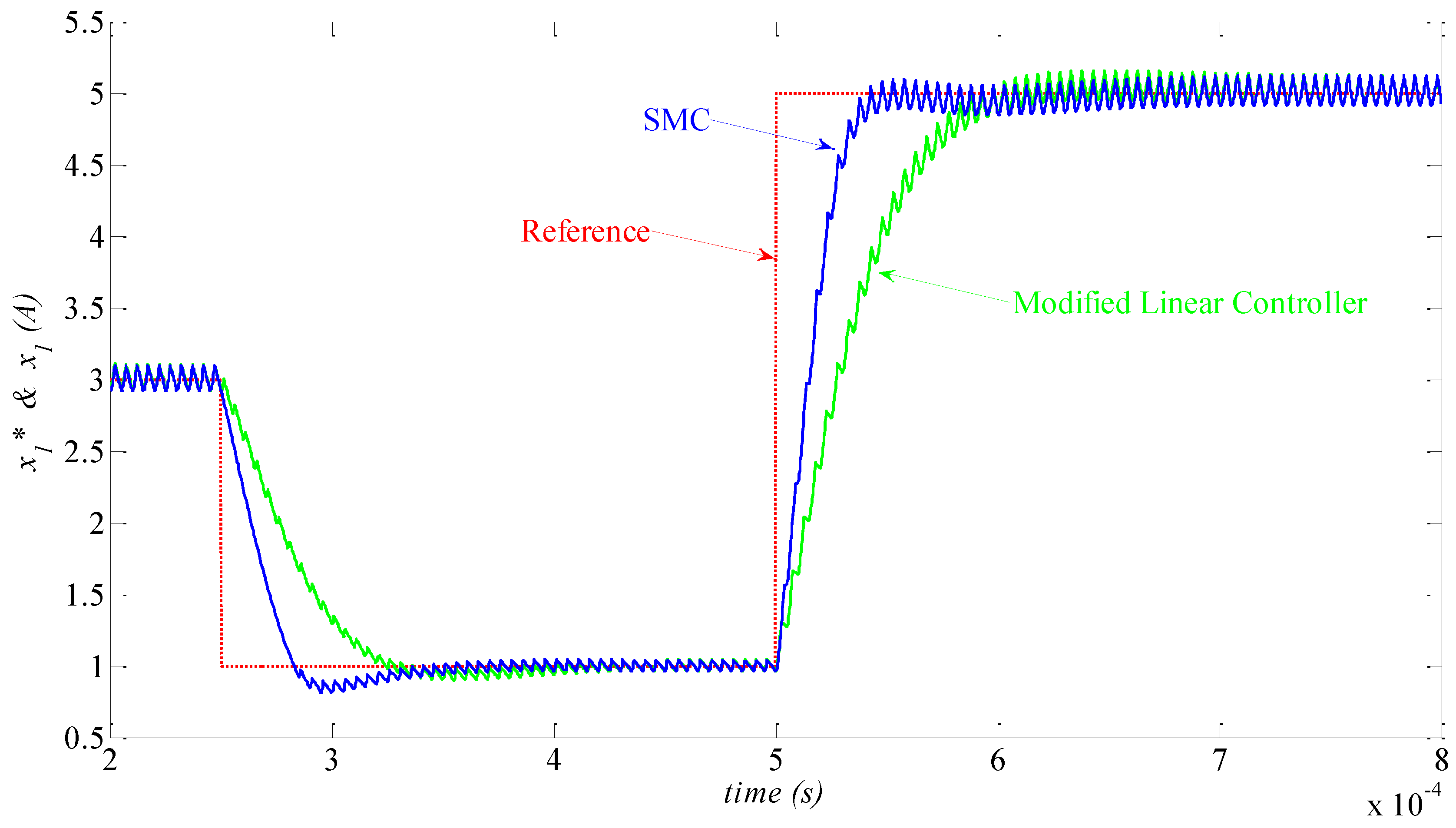
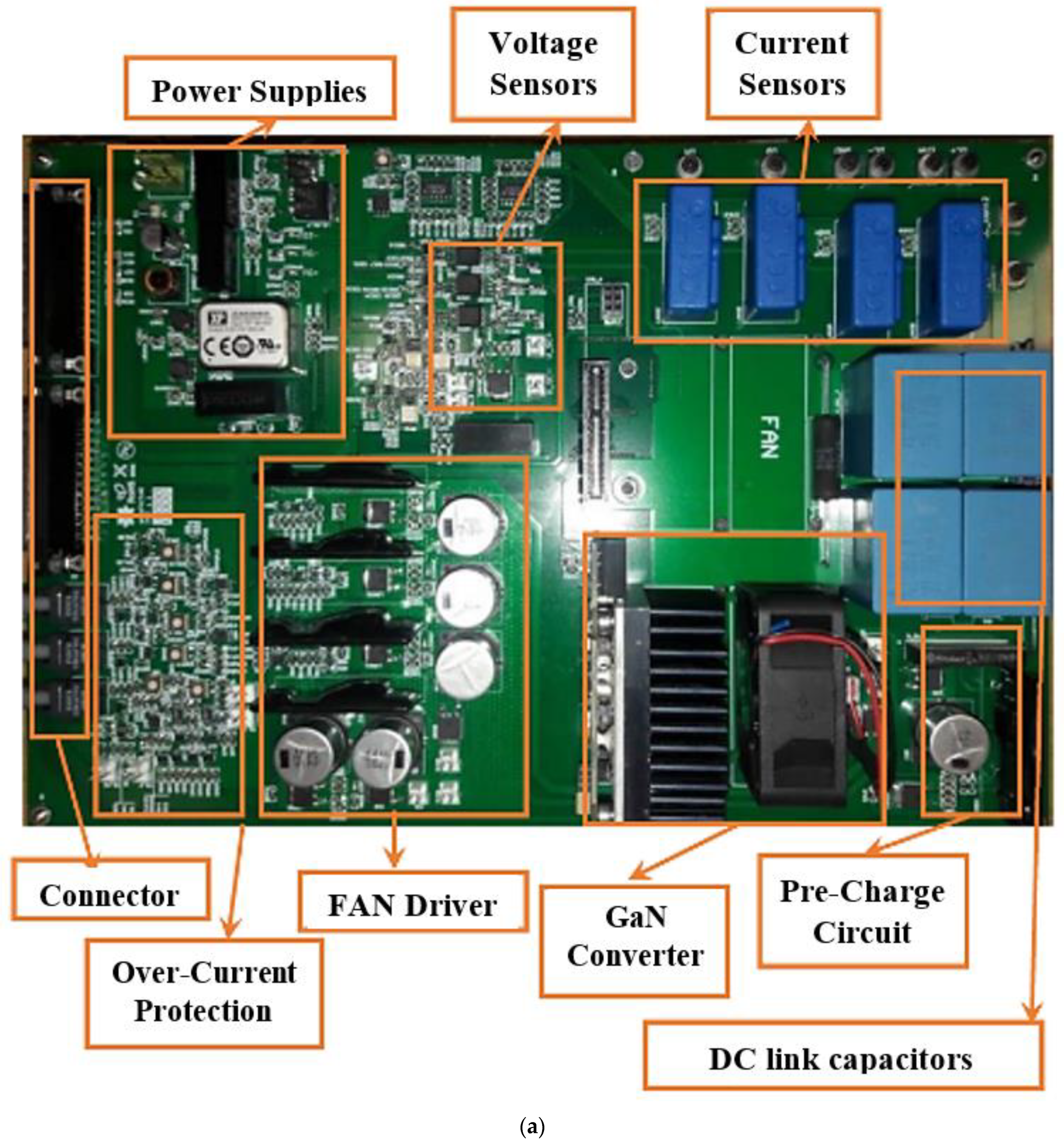
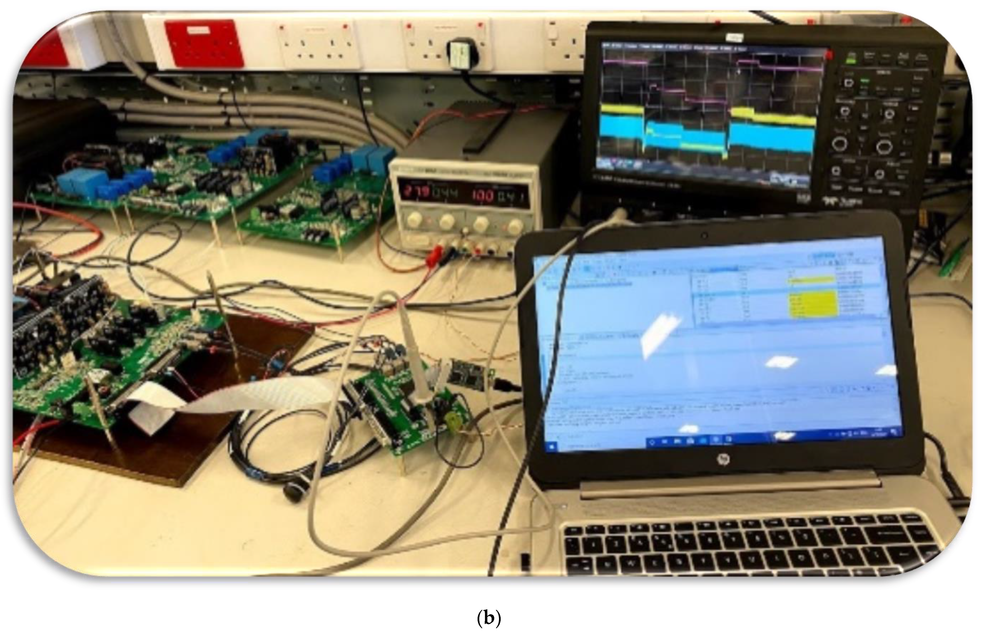
Moreover, the developed controller enjoys a simple control law. So, despite the fast switching of the GaN-based EMA emulator, the controller can be updated in each switching interval. It is shown that the proposed SMC has a superior transient response compared with conventional linear controllers. Using the TMS320F28335PGFA DSP from Texas Instrument, the experimental response of the designed synchronous DC-DC buck converter is evaluated as an EMA emulator. Despite the large changes of the load current, it is shown that the designed SMC is able to reject disturbances properly and stabilize the EMA current satisfactorily. Moreover, the comprehensive comparison of the proposed SMC controller and a PI-feedforward controller proved the superior performance of the developed closed-loop system, in terms of transient time response, robustness, and stability of EMA emulator.
2. Modelling of the EMA Converter
According to
Figure 1b, in order to emulate the EMA in more electric aircraft, a synchronous chopper with resistive load (
R) is employed. In the power topology,
VH is the input voltage that supplies the converter through a DC filter. The LC type filter is responsible for input current smoothing on the high voltage port of the converter.
Considering the PWM switching of the half-bridge converter, the equivalent input resistance, which is seen from the 270 V DC bus, can be calculated as follows:
where
is the averaged value of the duty-cycle and
is load resistance. So,
is the equivalent impedance of the load resistor (
R) that is transferred to the converter input port. In
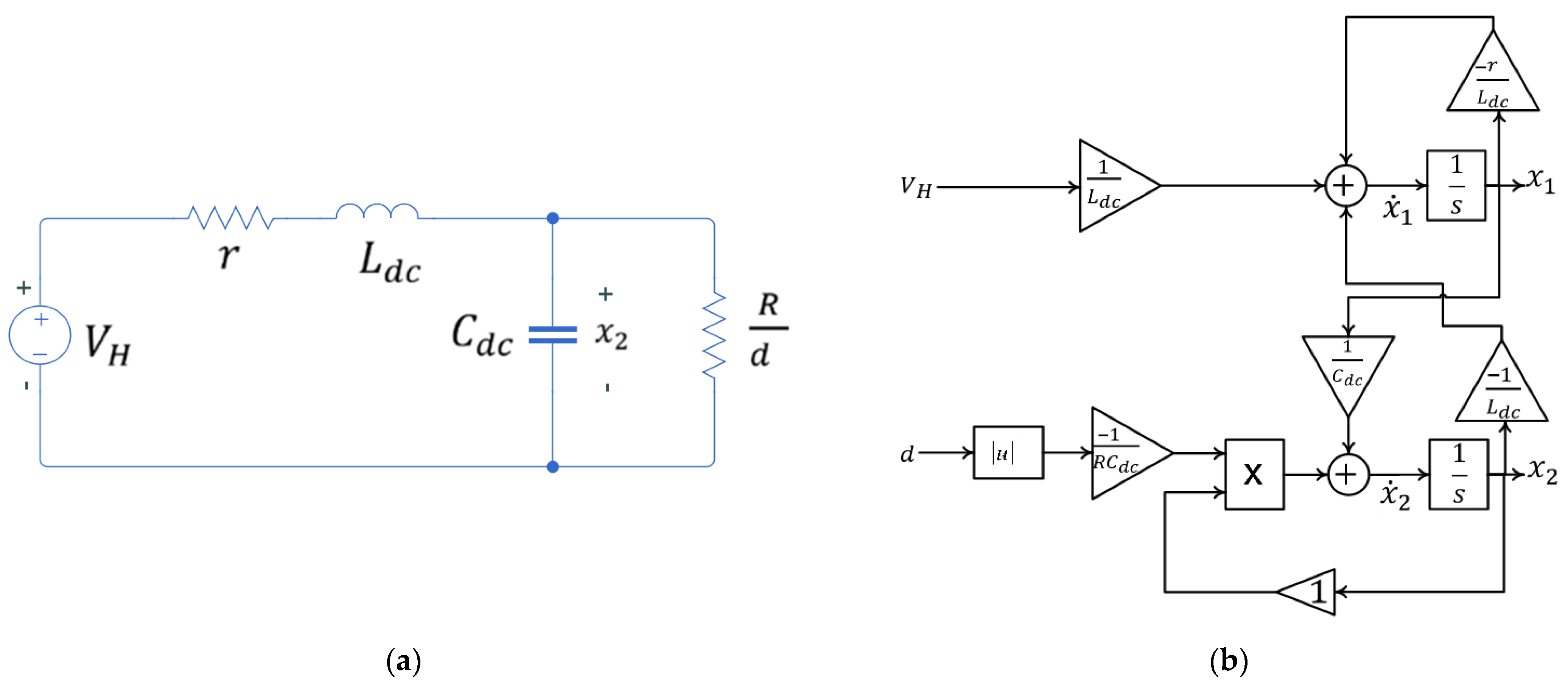
Figure 2, the averaged equivalent model of the converter is illustrated.
Considering
as a state vector of the system in
Figure 2a, the averaged state-space model of the EMA emulator can be written as follows. It should be noted that in this equation, the parameter
refers to the load resistance.
According to (2), dynamic model of the EMA emulator is illustrated in
Figure 2b. It is seen that the EMA converter is a nonlinear system. Considering small-signal perturbations of the system:
where
,
, and
are AC small perturbations of the parameters. Additionally,
,
, and
are DC steady-state quantities. Using Equations (3)–(5) in Equation (2) and rearranging the DC and AC terms, the linearized averaged state-space model of the system can be obtained.
and steady-state model of the system can be written as:
Considering
in Equation (7), the steady-state operating point of the EMA converter (
and
) can be calculated.
Applying Laplace transform to Equation (6) with zero initial conditions, small-signal transfer function (input current to duty-cycle) of the system can be written as:
where
and
are duty-cycle and capacitor voltage of the converter on the operating point.
4. Stability Analysis of the Linear Controller
In the previous section, a PI controller is designed for current control of the EMA emulator. Considering the skin and proximity effects in the winding, the AC resistance of inductor is a frequency-dependent parameter. So, from the control design viewpoint, equivalent series resistance (ESR) of the inductor is an uncertain parameter. In this section, the effect of ESR changes on the stability of the closed-loop controller is studied.
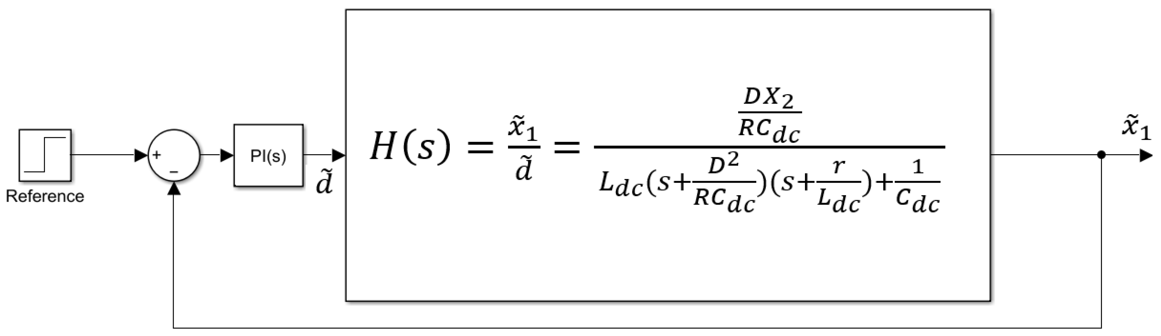
Considering
Figure 3, closed-loop transfer function of the system can be written as:
and the characteristic equation:
where:
Considering inductor ESR changes, to investigate the stability of the closed-loop system, Routh-Hurwitz stability criterion can be employed. So, the Routh array for generic cubic polynomial in (12) can be arranged as:
Considering nominal values of the converter elements in
Figure 1b and controller parameters (
and
), stability criteria can be simplified as follows. It is assumed that
on the operating point of the converter.
where
is ESR of the input inductor.
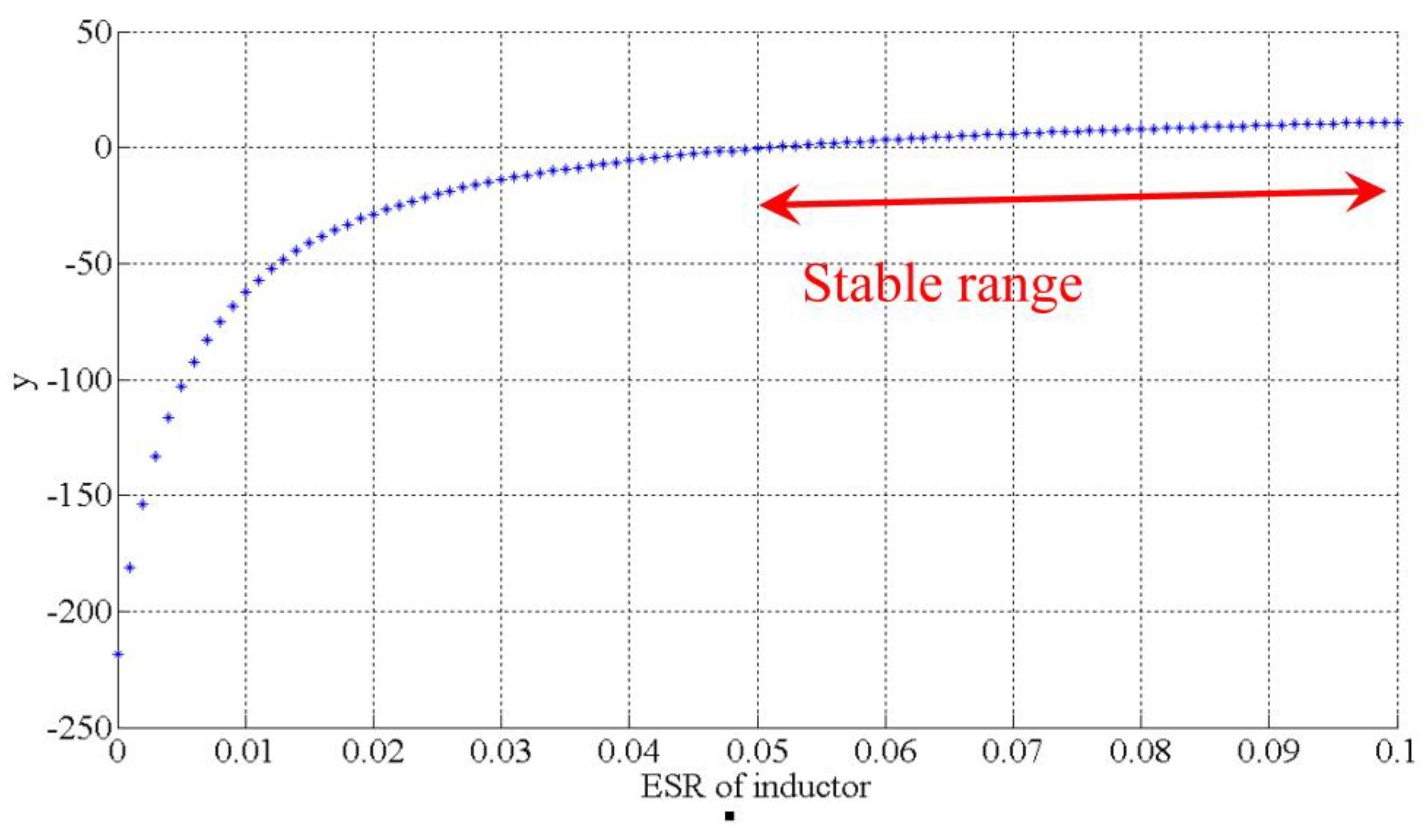
To find the stable range of converter,
is plotted in
Figure 5. It is seen that
is zero for
.
If it is assumed that if
, then
. So, Equation (17) can be simplified as
, and the stable range of the closed-loop system will be
, which is compatible with zero crossing point of the characterize equation in
Figure 5.
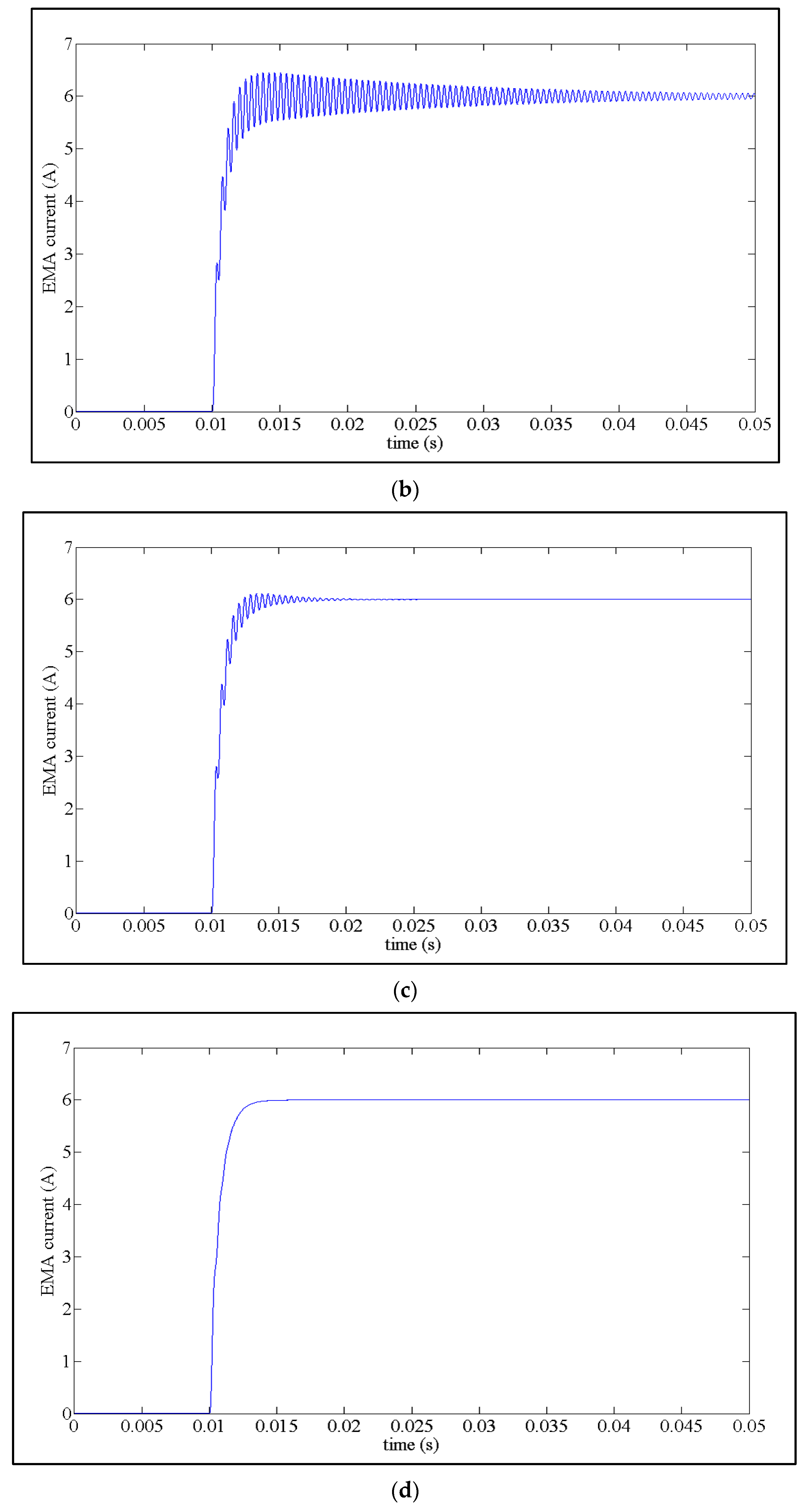
To investigate accuracy of the developed stability analysis, some simulations are done in MATLAB/Simulink. In
Figure 6, the step responses of the designed linear controller for different values of the ESR are shown. The reference value of the EMA current is stepped up from 0 A to 6 A at t = 0.01 s. It is seen that, for
, the response is unstable, which is compatible with the developed analysis. Additionally, for
, oscillations are completely damped in the step response.
6. Sliding Mode Controller Design for Input Current Control of the EMA Emulator
To improve the robustness of the closed-loop system against model uncertainties and disturbances, an SMC is developed for input current control of the EMA emulator. Despite the changes of converter operating point in a wide range, the SMC control is able to stabilize the closed-loop system satisfactorily.
At first, the equivalent SMC is designed according to certain nominal values of the model parameters. However, the uncertainties and required modifications for controller improvement will be studied in the next sections. Assuming the nominal values of the model parameters in
Figure 1b, such as
,
,
,
, and
(
stands for the nominal value), to simplify the matrix representation of state-space model, the following parameters can be defined considering Equation (2):
So, the averaged state-space model of the EMA converter in Equation (2) can be rewritten as follows, considering the nominal parameter.
To design the SMC, the error variables of the system can be defined as:
where
is reference value of the capacitor voltage (
). According to (8) and (9), and assuming that
, the reference of the capacitor voltage can be approximated as:
However, to eliminate steady-state error, Equation (23) can be rewritten as:
where
is a design parameter.
At first, nominal sliding surface is defined as:
If it is assumed that the converter dynamics are settled on the sliding surface, then
is obtained. As a result, in sliding mode, time derivative of the sliding surface will be zero, as well. According to (24) and (25), the time-derivative of the sliding surface can be written as follows.
By replacing for
from (21) into (26):
Considering the parameters nominal values, the equivalent SMC can be obtained by setting Equation (27) into zero.
By setting error variables into zero in Equation (28), the following equation can be obtained for steady-state operation, which is compatible with Equation (8):
8. Stability Analysis
Clearly, if the model parameters in (28) do not be equal to nominal values, then the proposed SMC in (28) cannot force the sliding surface and its time derivative into zero (
and
). So, in the presence of model uncertainty, the system response cannot be settled on the sliding surface. Hence, the developed equivalent SMC should be modified to achieve robust and stable behaviour from the closed-loop system. Considering model uncertainty, and according to Equation (27), the sliding surface derivative can be written as:
where
is system uncertain compressed function and
is sliding surface of the nominal parameters. Clearly, on the sliding surface,
. The system uncertainties are expressed by
in (32). To improve robustness of the designed controllers against model uncertainties, developed equivalent controller in (28) is revised as:
where
is system equivalent controller for nominal parameters. Obviously, controller gains should be selected to satisfy
. Additionally,
is a positive scaler. In (33),
modifies the reaching path of the controller toward sliding surface. Moreover,
is an estimation from highest value of the uncertain compressed function
Despite model uncertainties and load disturbances, it can be proved that the system response will certainly be on the sliding surface by using the modified controller in (33). To do so,
can be simplified by replacing (33) in (32).
If Lyapunov function is defined as:
where
, then time derivative of Lyapunov function will be:
By placing (35) in (37) and considering
, the time derivative of Lyapunov function can be simplified:
Assuming
and according to
, Equation (38) can be rewritten as:
Considering Equation (34), it is clear that
. Hence, the following equation can be written according to (39):
As and , the time derivative of the Lyapunov function in (40) will be a negative semi-definite function. So, the asymptotical stability of the system will be proved using modified SMC in (33) and as an estimation law.
9. Proposed SMC for EMA Emulator
To improve robustness of the system, in the previous section, the SMC controller has been modified. Additionally, an estimation law has been extracted for the proposed SMC. To cope with the model uncertainties, another approach for the modification of the equivalent SMC is presented:
If Equation (41) is employed as a SMC, despite system uncertainties, the asymptotical stability of the proposed controller can be proved by choosing . In this condition, the previous estimation rule will not be needed anymore.
By replacing (41) into (32):
If Lyapunov function and its time derivative are assumed as:
By replacing
from (42) in (43):
Considering
, Equation (44) can be simplified as:
As
is selected to be more than the uncertainty function (
):
Hence, despite the presence of model uncertainness and load change in the EMA emulator, it is observed that
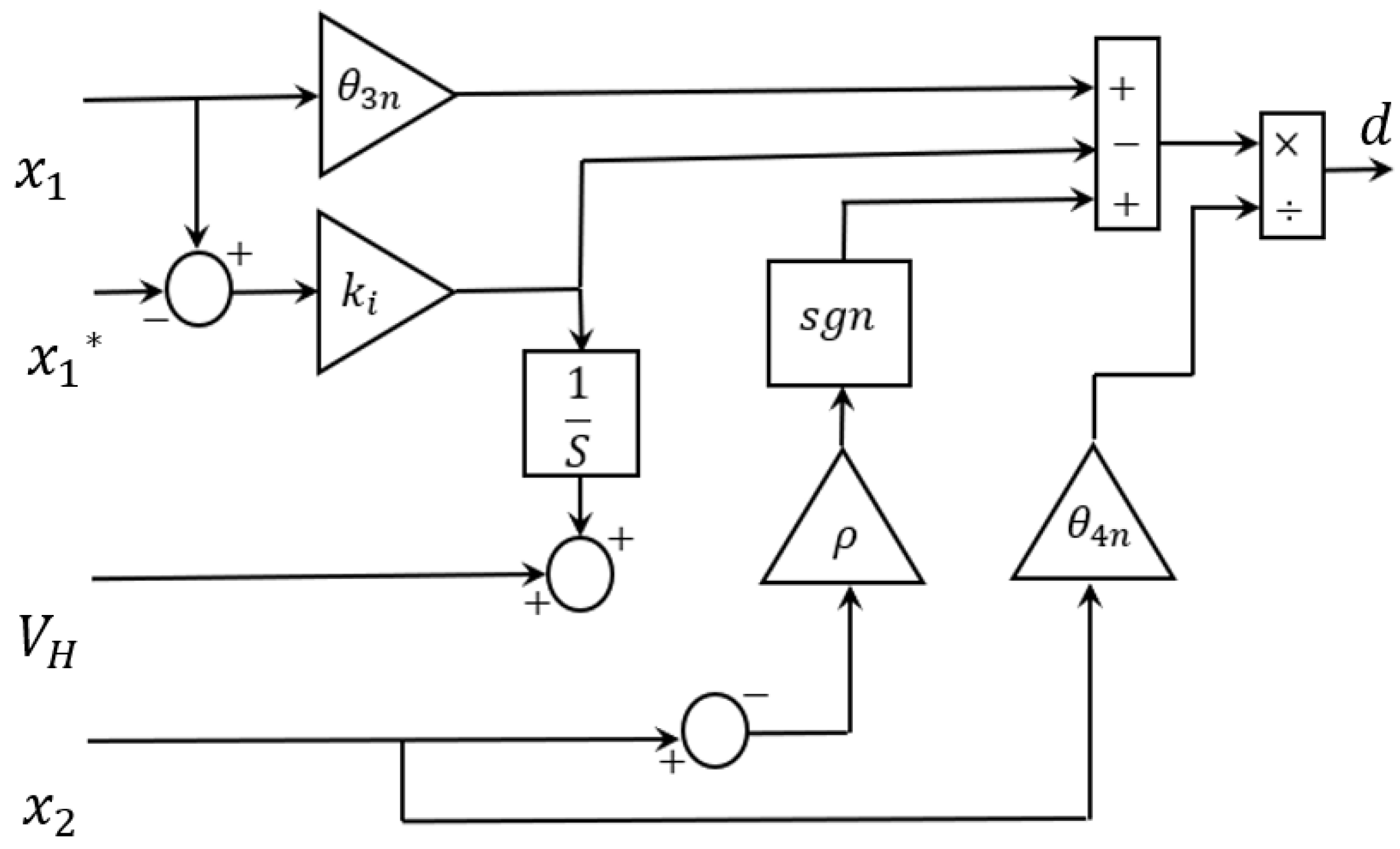
is a negative semi-definite function in (46), and as a result, asymptotical stability of the controller presented in (41) will be proven. Considering Equation (41), the block diagram of the implemented SMC is shown in
Figure 9.
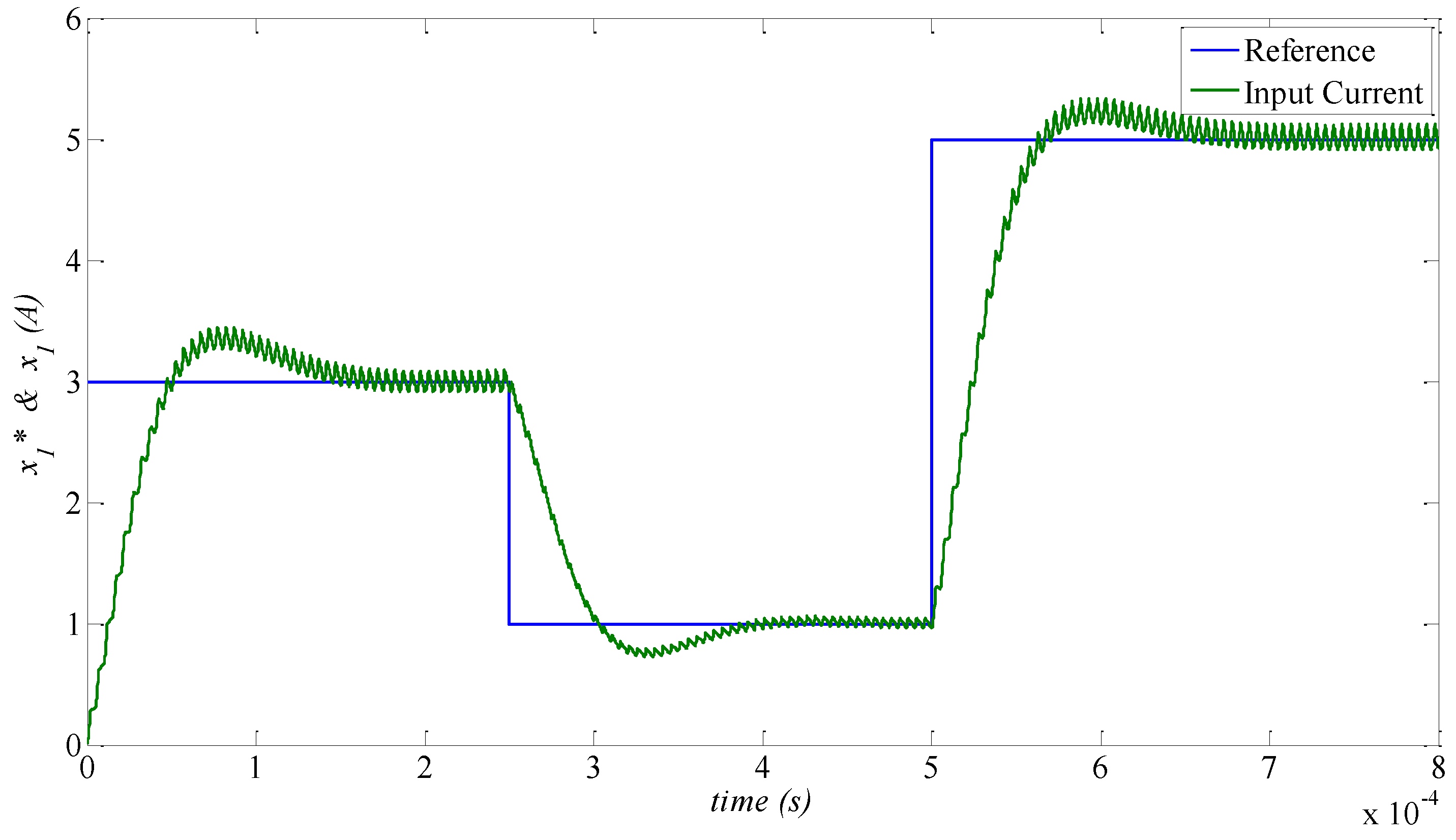
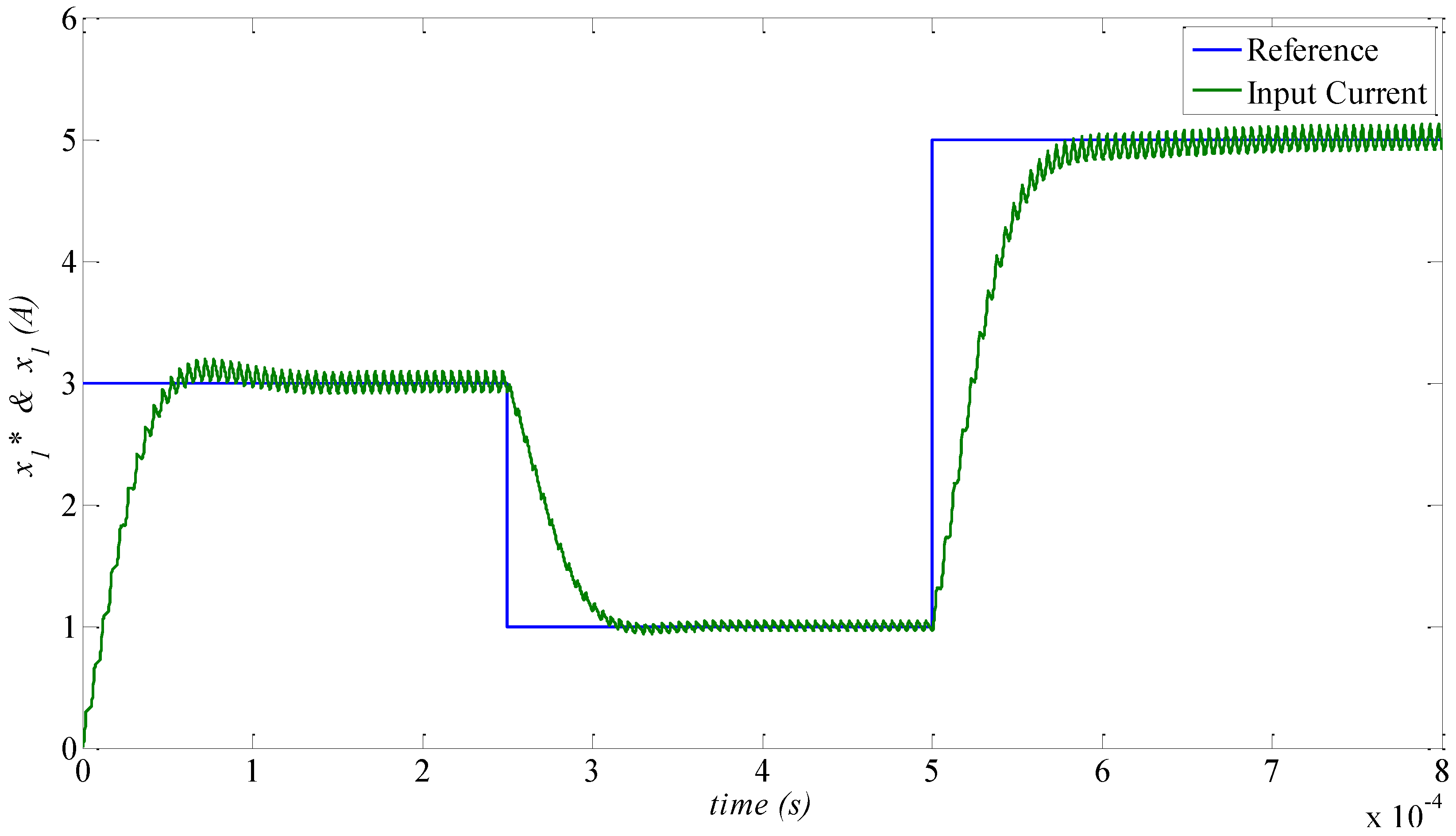
In
Figure 10, step response of the designed SMC in (41) is illustrated in similar condition with the previous simulations. It is seen that the rise/fall time of the inductor current is about
.
12. Conclusions
In this paper, the closed-loop control of the EMA emulator was studied using GaN based synchronous DC-DC buck converters. Due to the inherent challenges of controller design, e.g., the model nonlinearity, changes of the operating point in a wide range, and resonance issues of the input LC filter, it was shown that the linear PI-feedforward controller could not stabilize the closed-loop system against the model uncertainties. Hence, to cope with the mentioned issue, a novel fixed frequency SMC was developed for closed-loop stabilization of the EMA emulator. Using the Lyapunov stability criteria, the asymptotic stability of the developed controller was proven in the whole operational range of system, and it was proven that the SMC can reject the external disturbances, resonance issues of the LC input filter, and model uncertainties stably. The proposed nonlinear SMC controller enjoys a very simple control law. Hence, despite having very high switching and sampling frequencies, it can be easily implemented. The experimental response of the designed synchronous DC-DC buck converter was evaluated experimentally by implementing the control strategy in a TMS320F28335PGFA DSP from Texas Instrument. Moreover, the comprehensive comparison of the proposed SMC controller and a PI-feedforward controller proved the superior performance of the developed closed-loop system, in terms of the transient time response, robustness, and stability of the EMA emulator.


