Abstract
No alternatives are currently available to operate industrial furnaces, except for hydrocarbon fuels. Plant managers, therefore, face at least two challenges. First, environmental legislation demands emission reduction. Second, changes in the origin of the fuel might cause unforeseen changes in the heat release. This paper develops the hypothesis for the detailed control of the combustion process using computational fluid dynamic models. A full-scale mock-up of a rotary cement kiln is selected as a case study. The kiln is fired by the non-premixed combustion of Dutch natural gas. The gas is injected at Mach via a multi-nozzle burner located at the outlet of an axially mounted fuel pipe. The preheated combustion air is fed in (co-flow) through a rectangular inlet situated above the attachment of the fuel pipe. The multi-jet nozzle burner enhances the entrainment of the air in the fuel jet. A diffusion flame is formed by thin reaction zones where the fuel and oxidizer meet. The heat formed is transported through the freeboard, mainly via radiation in a participating medium. This turbulent combustion process is modeled using unsteady Favre-averaged compressible Navier–Stokes equations. The standard k- equations and standard wall functions close the turbulent flow description. The eddy dissipation concept model is used to describe the combustion process. Here, only the presence of methane in the composition of the fuel is accounted for. Furthermore, the single-step reaction mechanism is chosen. The heat released radiates throughout the freeboard space. This process is described using a P1-radiation model with a constant thermal absorption coefficient. The flow, combustion, and radiative heat transfer are solved numerically using the OpenFoam simulation software. The equations for flow, combustion, and radiant heat transfer are discretized on a mesh locally refined near the burner outlet and solved numerically using the OpenFoam simulation software. The main results are as follows. The meticulously crafted mesh combined with the outlet condition that avoids pressure reflections cause the solver to converge in a stable manner. Predictions for velocity, pressure, temperature, and species distribution are now closer to manufacturing conditions. Computed temperate and species values are key to deducing the flame length and shape. The radiative heat flux to the wall peaks at the tip of the flame. This should allow us to measure the flame length indirectly from exterior wall temperature values. The amount of thermal nitric oxide formed in the flame is quantified. The main implication of this study is that the numerical model developed in this paper reveals valuable information on the combustion process in the kiln that otherwise would not be available. This information can be used to increase fuel efficiency, reduce spurious peak temperatures, and reduce pollutant emissions. The impact of the unsteady nature of the flow on the chemical species concentration and temperature distribution is illustrated in an accompanying video.
1. Introduction
Rotary kilns are long cylindrical furnaces used in various material processing applications [1]. The production of cement is an important example. Driven by the goal to minimize operational costs, these furnaces have been studied extensively both by modeling [2,3,4] and experiments [5,6].
The objective of this paper is to model the non-premixed turbulent combustion of Dutch natural gas in the rotary kiln operated by the author’s industrial partner for the production of special-purpose cement. To render our work reproducible, the use of open-source software tools for mesh generation and combustion simulation is targeted. A considerable amount of effort in this paper is spent on identifying models for flow, combustion chemistry, and radiative heat transfer that provide an appropriate balance between complexity and computational cost. Another large part is devoted to identifying factors critical for the convergence of the numerical solution algorithm. Only limited amounts of experimental data or field measurements on the kiln are publicly available. This study is, thus, predominantly computational. It is, however, expected that an established baseline model for the combustion in the kiln will foster the dialogue of an experimental validation and more detailed modeling approaches.
In this paper, the kiln is assumed to be empty. The challenging task of modeling the heat transfer to the material bed and its effect on the combustion process is postponed to future work. By mixing the multi-nozzle fuel jet and preheated air stream, the resulting chemical reaction and the formation of the flame are studied. Flow recirculation stabilizes the flame. The paper seeks to understand how the flame shape fluctuates in the non-stationary flow. The model should capture how combustion products are formed in the flame and how they are convected downstream with the flow. Heat release in the flame and heat transport through the absorbing gas mixture to the outer walls of the furnace by radiative heat transfer ought to be quantified. The authors wish to translate the results of these simulations into guidelines for the operation of the kiln. Longer-term objectives of this work include lowering fuel consumption and pollutant formation, accounting for the variability of fuel composition, assessing the feasibility of alternative fuel blends, and obtaining a better grip on the heat transfer to the material bed.
The introduction of OpenFoam in this work is motivated by the software’s ability to simulate turbulent reactive flow in a full-scale three-dimensional geometry of industrial relevance. The simulation of turbulent combustion using OpenFoam has recently attracted considerable attention, e.g., [7,8,9]. Recent publications discussing the radiative heat and thermodynamics modeling in OpenFoam include [10,11,12,13]. This paper fills the gap in the publications on the use of OpenFoam for the simulation of industrial furnaces. The absence of expensive license fees allows us to introduce advanced computational fluid dynamical approaches in collaboration with our industrial partner that is, hitherto, unacquainted with these techniques. Conversely, the industrial partner does provide the scientific community with a challenging study case.
The modeling of the turbulent non-premixed combustion and heat transfer process in the kiln requires numerically solving the conservation of mass, momentum, and energy for the unsteady turbulent flow of the mixture of ideal gasses. Close to the burner outlet, the Mach number is equal to 0.6. A compressible flow formulation is, therefore, required. The conservation of energy is expressed using sensible enthalpy as the dependent variable to account for the heat released by combustion. An unsteady Reynolds Averaged Navier–Stokes model with density-weighted averaging closed by the two equation standard k- model with standard coefficients and standard wall functions is adopted. Details of the unsteady RANS model are given in e.g., [14] and references cited therein. Thermodynamics is expressed in terms of compressibility. The flow is solved using the extension of the PIMPLE algorithm [15]. Wave-transmissive boundary conditions for the pressure at the outlet patch are applied [16]. The combustion is modeled by adding to the flow model a set of convection–diffusion–reaction equations for the mass fraction of the fuel, oxidizer, and combustion products. A single-step reaction mechanism for methane and the eddy-dissipation concept with standard coefficients as the combustion model are employed. The radiative heat through participating media of gas mixture is modeled by adding to the flow model a non-linear diffusion equation for the first-order spherical approximation of the total radiative intensity. A constant absorption coefficient is used. Unlike in [17], the solid insulating lining is left out of consideration in this paper. Performing conjugate heat transfer computations is, thus, avoided. This paper instead makes use of a heat transfer condition on the outer shell of the cylinder.
This paper is a direct extension of the two previous papers [18,19]. In [18], the geometry of the kiln, the mesh generation using cfMesh, and the case setup are described. Simulation results for the non-reactive and reactive flow are established. In [19], case-specific guidelines to obtain stable convergence of the transonic non-stationary reactive flow simulations using reactingFoam are outlined. In [19], however, inflow conditions of preheated air that are of merely academic interest are used. The wall of the furnace was furthermore thermally insulated. The goal of this paper is to discuss how simulation results published in [19] change in case the more realistic inflow conditions for the oxidizer (and, thus, a more realistic air-to-gas ratio) are employed. The authors also wish to alleviate the restrictive condition of the insulation of the walls. Unlike previous work, this paper does not take the conjugate heat transfer to the insulating lining into account. A heat transfer condition on the walls of the gas domain is imposed instead. The modeling of conjugate heat transfer to the insulating lining of the kiln with the inflow conditions employed in this paper is left for future work.
The modeling of non-premixed combustion and radiative heat transfer are first illustrated using the reverseBurner tutorial case. This tutorial is part of the heat transfer tutorial section of the OpenFoam distribution. It illustrates the inflow of air and gaseous fuel in co-flow through separate channels in a U-shaped duct, their chemical reactions, and the heat transfer away from the flame. It, therefore, shares various features with the combustion in the kiln. The version of the tutorial available in OpenFoam-v1906 does not include radiative heat transfer. The authors, therefore, extended this tutorial and activated the radiative heat transfer model. Numerical results show that the chemical source for the enthalpy equation is large in a thin reaction zone where fuel and oxidizer mix. The sink term for radiative heat transfer is large in the same zone.
This paper contains three sets of results relative to the kiln. In the first set, the authors show that the nominal inflow of methane and preheated air causes a long diffusion flame to form downstream from the burner. The flame fluctuates in the unsteady flow. The spatial distribution of the chemical source terms and thus the flame is mainly determined by flow-induced mixing and thus by the internal and external recirculation vortices. The single-sided supply of the oxidizer from the top of the burner pipe only pushes the time-average flame downwards to the lining. A large recirculation vortex underneath the burner pipe transports the hot oxidizer into the flame. In the second set of results, the authors show how heat is transferred from the flame into the freeboard and the furnace walls. The wall radiative heat flux peaks at the tip of the flame. In the third set, the authors show how thermal nitric oxide is formed in the flame and transported downstream toward the outlet.
This paper is structured as follows: In Section 2, the modeling of turbulent non-premixed combustion and heat transfer in the kiln and its implementation in OpenFoam is described. In Section 3, the numerical results for the reverseBurner test case are presented. In Section 4 and Section 5, the kiln test case and the numerical results are presented, respectively. In Section 6, the conclusions of the paper are summarized.
2. Computational Fluid Dynamics of Turbulent Non-Premixed Combustion
In this section, the computational fluid dynamics models for the non-premixed turbulent combustion in the kiln that will be solved using OpenFoam will be presented. This model consists of four submodels. The first submodel is for the unsteady turbulent compressible flow of the mixture of fuel, oxidizer, and combustion products. The second is a model for the non-premixed combustion of fuel and oxidizer. The third is for the radiative heat transfer in the gas mixture. The fourth is a model for evaluating the thermal nitric oxide mass fraction in the post-processing stage of the reactive flow model. For details on turbulent combustion modeling and pollutant formation, the reader can refer to the references, e.g., [20,21,22]. More information on the modeling of radiative heat transfer can be found in e.g., [23].
2.1. Unsteady Compressible Turbulent Flow of the Gas Mixture
The unsteady compressible turbulent flow is modeled by the conservation of mass, momentum and enthalpy. These conversation equations are density-weighted and ensemble-averaged. Resorting to an unsteady Reynolds-averaged Navier–Stokes (URANS) allows the avoidance of the computational complexity of more detailed models, such as (delayed) detached eddy ((D)DES), large eddy (LES), or hybrid RANS-LES simulations. The additional computational cost of these more advanced models derives from the use of a smaller time step on a finer mesh required to resolve smaller scale features. The formulation of more quantitative statements on the accuracy lost in the URANS model and the additional computational cost of the more detailed models is left for future research. The averaged density and velocity components are denoted by and , respectively. The standard two-equation k- turbulence model is adopted to model unclosed terms. Standard wall functions are used. On the outlet, we apply a wave-transmissive boundary condition for the pressure with an appropriate setting of the parameter [16]. The governing equations are first discretized in space and time and subsequently solved using an extension of the PIMPLE algorithm that takes the pressure–velocity–density coupling into account [24] and [15]. Using the turbulent kinetic energy k and the turbulent dissipation rate , the turbulent eddy viscosity is defined as
where is a k- model constant. More details on the flow model can be found in the literature cited above.
2.2. Non-Premixed Combustion of Gaseous Fuels
The combustion is assumed to occur in a regime in which diffusion flames with thin reaction fronts are formed. With this assumption, the turbulent mixing time scale dominates the chemical time scale. The Damköhler number is, thus, much larger than one. To model this combustion regime, the eddy dissipation concept combustion model [25,26] is used.
We simplify Dutch natural gas to its main component—methane. The single-step irreversible global reaction mechanism
is employed. This reaction has an enthalpy of combustion equal to of CH. The mass fraction of four chemical species (), thus, needs to be tracked. The presence of the inert N as the fifth species in the gas mixture facilitates ensuring that the mass fractions sum up to one. The one-step mechanism predicts peak temperatures that are too high and does not take the presence of carbon monoxide into account. To address these limitations, resorting to more detailed reaction mechanisms is required.
The mass fraction of the chemical species s and its Favre average are denoted by and for , respectively. The latter is governed by a convection–diffusion–reaction with the source term . This source term is given by the eddy dissipation (EDC) combustion model. All species are assumed to have the same molecular mass diffusivity coefficient denoted by . The conservation equation for can then be written as
where is the turbulent Schmidt number for the transport of species. The source term for species s is given by
where and are the characteristic length and time scales, and where and are obtained from the transport equation and evolving the chemistry over a time interval starting from , respectively. Suitable boundary conditions need to be supplied. The previously discussed flow model provides the required values for , , and . Computed values for allow updating and the combustion heat release term given by
where and are the heat of combustion of the fuel and chemical source term for the fuel. The value for is given after Equation (2).
2.3. Radiative Heat Transfer in Gas Mixture
The literature provides several models to compute the radiative heat transfer to various degrees of accuracy. This paper adopts the so-called P1 model without any scattering effects. This model solves a non-linear diffusion equation for a single scalar field at each update of the radiative field. It yields a good balance between accuracy and computational cost. The P1 model assumes medium isotropy in space. This assumption is valid if the optical thickness of the medium is large. It computes the total radiative intensity G with Favre average via the following diffusion equation
The boundary condition is written in terms of the wall emissivity, denoted by . This quantity is equal to zero on the symmetry patch, to one on the inlet and outlet patches, and to on all other patches. The Marshak boundary condition for can then be written as
where the vector with component is the unit normal vector on the boundary patch. The radiative heat flux is denoted by . In case the P1 model for radiative heat transfer is used, the energy sink term due to radiation is given by
where . is the Stefan–Boltzmann constant. Here, we assume that the Favre average of the product of the absorption coefficient and the total intensity is given by the product of their Favre averages. Similarly, we assume that the Favre average of the fourth power of temperature is given by the fourth power of the Favre average of the temperature. The turbulence–radiation interaction is thus neglected.
2.4. Zeldovich Thermal Nitric Oxide Post-Processing
The thermal nitric oxide mass fraction is computed in post-processing using the three-step Zeldovich model. This model is described in, e.g., [27]. The model requires as input the mass fraction of O and OH. These are evaluated assuming that chemical equilibrium has been reached. The thermal nitric oxide mass fraction is transported by the frozen velocity field provided by the flow model. The implementation of this thermal nitric oxide model in the NOxFoam solver is developed in the master thesis [28].
2.5. Implementation in chtMultiRegionFoam and reactingFoam
A cell-centered finite volume method is adopted for the spatial discretization of the combustion model introduced above. A finite difference method is subsequently used to discretize the model in time. The resulting set of ordinary differential equations is solved using an extension of the PIMPLE algorithm for the velocity-pressure coupling that takes the variability of density into account. This segregated solution approach is implemented in the chtMultiRegionFoam and the reactingFoam applications. At each pressure–velocity–energy iteration, the transport equations for the turbulent kinetic energy k, turbulent dissipation rate , chemical species , and the total incident radiation are solved. This allows one to update the turbulent viscosity , the source terms , and the sink term in the enthalpy conservation equation.
3. The reverseBurner Tutorial Case for Non-Premixed Turbulent Combustion
In this section, we discuss the case setup and some numerical results for the reverseBurner tutorial case. This case is included in the heat transfer tutorial section of the OpenFoam distribution. We added radiative heat transfer to the tutorial case. A turbulent non-premixed combustion process caused by the co-flow of a fuel jet and fuel stream is simulated. The case, thus, has similar features to the kiln. The goal of introducing this tutorial case here is to discuss OpenFoam solver capabilities. We wish to highlight the similarities and differences in the combustion and radiative heat transfer with the kiln case. We in particular intend to investigate the spatial distribution of the source terms and in the energy equation.
In the reverseBurner case, the fuel and oxidizer are injected at room temperature through separate channels in co-flow into a main U-shaped combustion chamber. The mixture of fuel and oxidizer is ignited and reacts further downstream. This reaction causes the formation of heat and combustion products. The combustion chamber is surrounded by a solid material insulating lining. The conjugate heat transfer is solved using the chtMultiRegionFoam solver, which extends the capabilities of the compressible transient rhoPimpleFoam solver with heat transfer from a fluid to a solid domain. The fluid and solid domains are coupled using interface coupling conditions implemented in the compressible::turbulentTemperatureCoupledBaffleMixed boundary conditions. The combustion in the fluid domain is activated by the file combustionProperties in the constant folder. The combustion model is set to the eddy-dissipation concept combustion model. The fuel and the reaction mechanism are set to methane and single step, respectively. We added the radiative heat transfer using the P1-model by adding the file radiationProperties in the same folder. The case is solved using the PIMPLE algorithm until a steady state is reached.
Numerical results for the source terms and obtained at convergence are shown on the left and right of Figure 1, respectively. Both source terms are seen to be large in a thin reaction zone where the fuel and oxidizer mix. Due to the geometry being two-dimensional, only limited mixing occurs. The reaction zone, therefore, extends to the outlet.
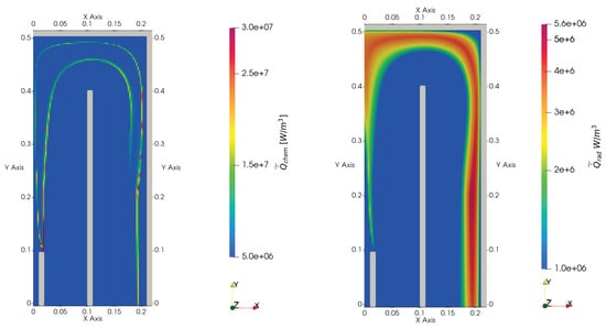
Figure 1.
Source term in the energy equation given by chemistry (left, in W/m) and sink term given by radiative heat transfer (right, in W/m) in the reverseBurner tutorial case.
In the simulation of the cement kiln, we will reveal similar thin reaction fronts. In the kiln case, however, the multi-jet nozzles ensure better mixing. The reaction front, therefore, only extends a few kiln diameters into the freeboard.
4. Cement Kiln: Geometry Definition, Mesh Generation, and Boundary Conditions Imposed
In this section, we describe the geometry, the mesh, and the boundary conditions used in the simulations of the kiln.
4.1. Geometry Definition
The kiln is represented on the true scale. The same geometry of the freeboard as published in [18,19] is employed. The insulating lining, however, is omitted. The geometry is enclosed by a long cylinder that is slightly tilted about its center axis. Figure 2 shows that the burner pipe is placed on the center axis at the lower end of the kiln. The burner is fitted at the end of the burner pipe. The burner pipe is fixed to the kiln hood. At the top of the kiln hood, the rectangular secondary air inlet is located. The top end of the cylinder is left open.
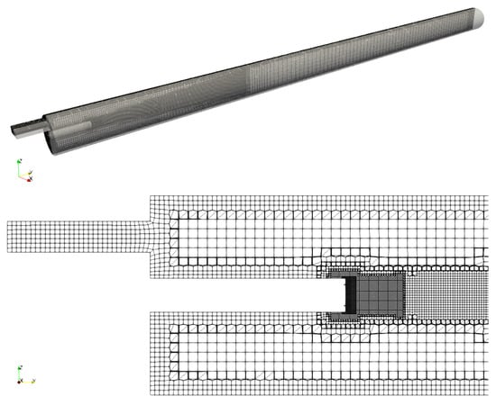
Figure 2.
Mesh on the plane (top) and a detail of this view near the burner outlet (bottom).
The burner has two sets of eight nozzles that form two regular octagons with the same center but an unequal radius. The nozzles on the inner octagon are angled away from the center axis of the kiln, while those on the outer octagon are parallel to this axis. A cooling slot surrounds the nozzles. The arrangement of the nozzles enables proper fuel and air mixing. The burner design is therefore accurately taken into account. The nozzles are represented as cylinders. To allow for a proper definition of the inlet conditions on the angled fuel nozzles, the geometry model defines inlet patches perpendicular to the axis of the inclined nozzles. This improves on the previous work published in [18]. The perpendicular inlet patches significantly benefit the convergence of the numerical solution procedure.
The cross-section of the fuel nozzles is very small compared to the length of the kiln. This renders the mesh construction process to be demanding. The mass flow rate through the fuel nozzles is high enough to violate the assumptions of incompressible flow. Turning to compressible flow computation thus becomes unavoidable.
In the remainder of the paper, the symmetry plane cutting perpendicular through the air inlet is referred to as the plane . This plane is shown on top of Figure 2.
4.2. Mesh Generation
The cfMesh package [29] was used to construct a mesh of million cells. The cell size is reduced in two regions: at the burner outlet, to capture the large fuel mass flow rate; near the furnace walls, to resolve large temperature gradients. The mesh on the plane is shown on top of Figure 2. A detail of this view near the burner outlet is shown at the bottom of the same figure. The output of checkMesh can be found in the appendix of [19]. The mesh generation process can be entirely scripted. This facilitates the mesh coarsening and refinement process in a mesh dependency study. Such a study is postponed to future work.
4.3. Imposed Boundary Conditions
We apply a nominal mass inflow rate for the gaseous fuel through the burner and the air through the secondary air inlet. The air is preheated to 550 degrees Celsius. With these settings, the air-to-gas ratio in mass is equal to nine. Unlike in [3] and previous work by the same author, the air enters the kiln from above the fuel pipe only. Compared to our previous work [19], much more air enters the kiln.
On the external furnace walls, we apply the externalWallHeatFluxTemperature boundary conditions to allow heat to escape to the environment mainly by radiative heat transfer. The insulating properties of the lining are accounted for in the boundary condition.
On the outlet, we prescribe a wave transmissive condition for the pressure. At the walls, we employ standard wall functions, a constant thermal absorption coefficient equal to and a wall emissivity value equal to .
5. Numerical Results
In this section, we report numerical results obtained for the kiln. We subsequently discuss the results for the computed flow field, the species concentration, the temperature, the wall heat flux, and the thermal nitric oxide concentration. We will show snapshots of computed results. Given the unsteady nature of the flow, the results depend to some extent on the time stamp. We employ the same time step throughout the entire section.
5.1. Results for the Flow Field
A snapshot of the computed axial velocity on the plane and the streamlines on the same plane are shown in Figure 3. The axial velocity plot shows the high-speed fuel jet in the center and the low-speed air jet at the top. The inflow of air from the top of the fuel jet makes the latter bend downwards. The axial velocity peaks at . The two-dimensional streamline plot shows two recirculation vortices: one above the fuel jet and one below. The first and second are reminiscent of a Craya–Curtet and a bluff body type flow. Flow patterns similar to the ones reported here have been discussed in, e.g., [30]. These recirculation vortices will aid in explaining the observed species concentration in the next subsection.
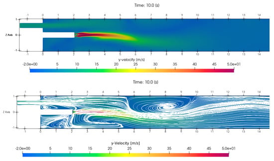
Figure 3.
Snapshot of the computed axial velocity (top) and streamline plot (bottom) on the plane .
A snapshot of the computed Mach number on the center plane is shown in Figure 4. This figure shows that the Mach number exceeds the limit of 0.4 in a region close to the burner outlet. The use of a compressible flow solver and thermodynamics based on the compressibility is thus required.

Figure 4.
Snapshot of the computed Mach number on the plane . The largest Mach number is equal to .
To gain a better understanding of the unsteady nature of the flow, we recorded the computed axial velocity component and the pressure over a period of time at two probe points. Both probe points are located on the center axis of the kiln. The first is located close to the burner outlet at , where L denotes the length of the kiln. The second is located close to the kiln outlet at . The time-domain discrete Fourier transform of the four signals is plotted in Figure 5. This figure shows that near the inlet the axial velocity and pressure vary at various frequencies. At the outlet, the set of frequencies has been reduced. The pressure at the outlet varies at a single dominant frequency of . We link this frequency to the resonant acoustic frequency of a cylinder of length L open at both ends. The axial velocity at the outlet varies at two dominant frequencies. The first is the resonant frequency. The second is a lower frequency mode. Compared to results in [19], results of the frequency domain analysis have changed insignificantly due to the increase of the mass flow rate of the combustion air flow from small to nominal values. This seems to suggest that the frequency content of the signals is mainly determined by the mass flow rate through the burners.

Figure 5.
Time-domain discrete Fourier transform of axial velocity (top) and pressure (bottom) recorded at probe points located at where (left) and (right). L denotes the length of the kiln.
5.2. Results for Species Concentration
A snapshot of the computed species concentration for methane, oxygen, and carbon dioxide on the center plane is given in Figure 6. This plot shows how the oxidizer and fuel are consumed, and combustion products are formed. The oxidizer and fuel are entirely consumed a few kiln diameters after being injected into the kiln. This finding is in contrast with the results in [19]. The front in the oxygen concentration perpendicular to the axial direction is caused by the top recirculation vortex shown in Figure 3. Part of the oxygen is transported to an area below the burner pipe. The results for species concentration compare favorably with those generated for the same configuration using commercial software using a similar finite volume formulation in [31].
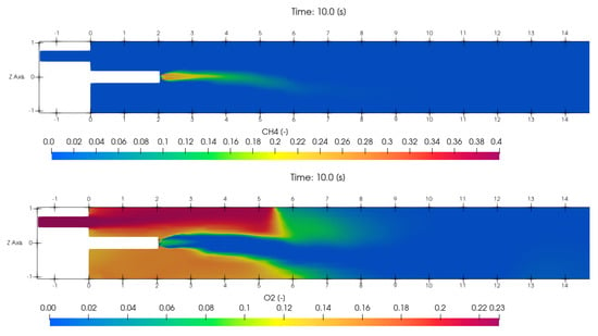

Figure 6.
Snapshot of the computed mass fraction of methane (top), oxygen (middle), and carbon dioxide (bottom) on the plane .
5.3. Results for Temperature
A snapshot of the computed chemical source term on the plane , the computed temperature on the same plane, and the computed temperature on the exterior wall of the kiln is shown in Figure 7.
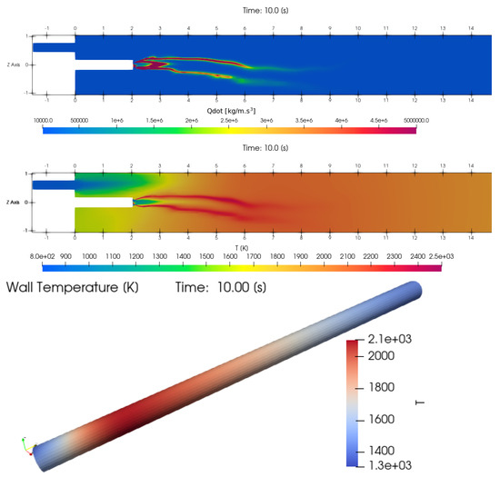
Figure 7.
Snapshot of the computed combustion source term on the plane (top), the computed temperature on the plane (middle), and the temperature on the outer wall (bottom).
The spatial distribution of shows two thin reaction fronts formed on the edges of the jet leaving the burner shown in Figure 3. The top and bottom front coincide and are caused by the inflow of air through the air inlet channel and the recirculation of air underneath the fuel pipe, respectively. The value of on the plane peaks at . Unlike the reverseBurner results reported in Figure 1, the reaction front only extends a few kiln diameters into the freeboard. This is ascribed to the better mixing properties of the multi-jet burner.
The computed temperature on the plane is large in the reaction front and convected further downstream. The temperature peaks on the plane and the exterior wall of the kiln peak at and , respectively. These elevated temperatures are required in the treatment of the raw materials of special-purpose cement.
The computed temperature on the lateral surface of the kiln is plotted in Figure 8. A good agreement with results published in [31] is obtained.
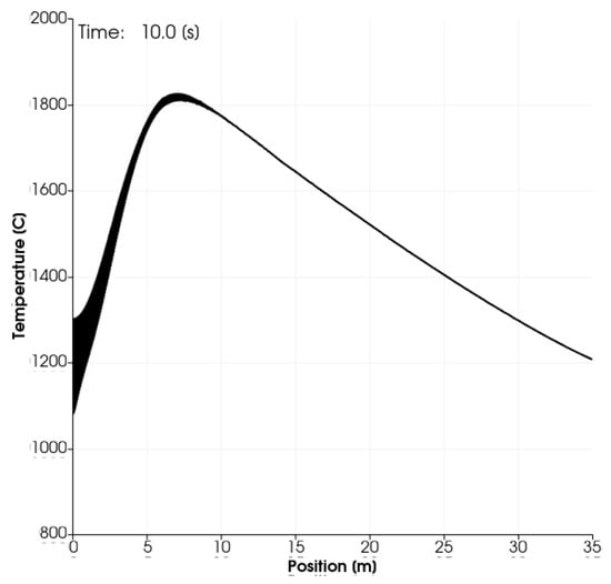
Figure 8.
Plot of the temperature on the wall of the kiln.
5.4. Results for Radiative Heat Transfer Quantities
A snapshot of the computed radiation sink term on the plane and the computed wall heat flux on the exterior wall of the kiln is shown in Figure 9.
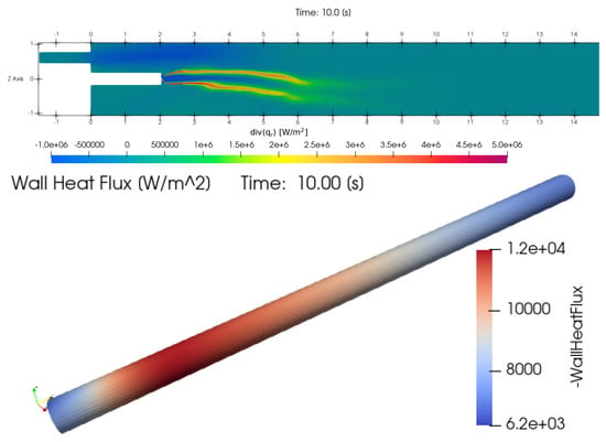
Figure 9.
Snapshot of the computed radiation sink term on the plane (top) and the computed wall heat flux (bottom).
The computed values for are large in the reaction zone. Values in the figure were truncated to fit the scale . The plot of the wall heat flux shows that most of the heat transfer to the ambient environment occurs at the hottest section of the kiln.
5.5. Results for Thermal NO Concentration
Numerical results related to the thermal NO mass fraction computed using a frozen field as input are shown in Figure 10 and Figure 11. Figure 10 shows the source term in the transport equation for the thermal NO concentration computed on the plane after of simulation time. The figure shows that thermal NO is formed in the vicinity of the flame. Figure 11 shows the resulting thermal NO concentration. Thermal NO is shown to be formed in the flame and to be transported and diluted downstream towards the outlet. The computed mass fraction in the flame and the outlet equals and (dimensionless), respectively.

Figure 10.
Computed thermal NO source term (in ) after of simulation time.

Figure 11.
Computed thermal NO mass fraction (dimensionless) after (bottom) of simulation time.
6. Conclusions
A computational fluid dynamics model for the non-premixed turbulent combustion of natural gas in a cement kiln in OpenFoam was developed. This model consists of an unsteady Reynolds-averaged Navier–Stokes model for the compressible turbulent flow, an eddy-dissipation concept model for the non-premixed combustion, a single-step chemical reaction model for methane, and a P1-model with a constant absorption coefficient for the radiative heat transfer. After discretization in space and time, the flow model is solved using the PIMPLE algorithm that takes the pressure–velocity–density coupling into account. At each iteration, the combustion model, the radiative heat transfer model, and the corresponding source terms in the energy equation are updated. The thermal nitric oxide concentration is computed in the post-processing stage using a Zeldovich algorithm. The formation of a long diffusion flame with thin reaction fronts downstream from the burner was simulated for the first time using public-domain software tools. The flame is shown to bend downwards due to the top inflow of secondary air. The heat is transferred through the freeboard and to the ambient environment mainly via radiation. The areas of the largest temperature and thermal nitric oxide concentration coincide. The results obtained agree reasonably well with the results obtained earlier using commercial software via a similar finite volume formulation. The results are, therefore, indispensable as input to minimize fuel consumption, lower pollutant emissions, and introduce alternative fuels; the results meet stringent productivity constraints. This paper, therefore, presents an excellent point of departure for the development of more detailed models.
Author Contributions
Conceptualization, D.L., M.T.; Methodology, D.L., M.T.; Software, M.T., F.J.; Validation, D.L., M.T., F.J.; Formal Analysis, D.L., M.T.; Investigation, D.L., M.T.; Resources, D.L.; Data Curation, D.L., M.T., F.J.; Writing—original draft preparation, D.L., M.T.; Writing—review & Editing, D.L., M.T.; Visualization, M.T.; Supervision, D.L.; Project Administration, D.L. All authors have read and agreed to the published version of the manuscript.
Funding
This research received no external funding.
Institutional Review Board Statement
Not applicable.
Informed Consent Statement
Not applicable.
Data Availability Statement
Not applicable.
Conflicts of Interest
The authors declare no conflict of interest.
References
- Boateng, A. Rotary Kilns: Transport Phenomena and Transport Processes; Elsevier Science: Amsterdam, The Netherlands, 2015. [Google Scholar]
- Giannopoulos, D.; Kolaitis, D.; Togkalidou, A.; Skevis, G.; Founti, M. Quantification of Emissions from the Co-Incineration of Cutting Oil Emulsions in Cement Plants: Part I: NOx, CO and VOC. Fuel 2007, 86, 1144–1152. [Google Scholar] [CrossRef]
- Larsson, I.S.; Lundström, T.S.; Marjavaara, B.D. Calculation of kiln aerodynamics with two RANS turbulence models and by DDES. Flow Turbul. Combust. 2015, 94, 859–878. [Google Scholar] [CrossRef]
- Elattar, H.F.; Specht, E.; Fouda, A.; Rubaiee, S.; Al-Zahrani, A.; Nada, S.A. Swirled Jet Flame Simulation and Flow Visualization Inside Rotary Kiln?CFD with PDF Approach. Processes 2020, 8, 159. [Google Scholar] [CrossRef]
- Gunnarsson, A.; Bckstrm, D.; Johansson, R.; Fredriksson, C.; Andersson, K. Radiative heat transfer conditions in a rotary kiln test furnace using coal, biomass, and cofiring burners. Energy Fuels 2017, 31, 7482–7492. [Google Scholar] [CrossRef]
- Edland, R.; Smith, N.; Allgurén, T.; Fredriksson, C.; Normann, F.; Haycock, D.; Johnson, C.; Frandsen, J.; Fletcher, T.H.; Andersson, K. Evaluation of NOx-Reduction Measures for Iron-Ore Rotary Kilns. Energy Fuels 2020, 34, 4934–4948. [Google Scholar] [CrossRef]
- Chen, Z.X.; Langella, I.; Swaminathan, N.; Stöhr, M.; Meier, W.; Kolla, H. Large Eddy Simulation of a dual swirl gas turbine combustor: Flame/flow structures and stabilisation under thermoacoustically stable and unstable conditions. Combust. Flame 2019, 203, 279–300. [Google Scholar] [CrossRef]
- Tekgül, B.; Peltonen, P.; Kahila, H.; Kaario, O.; Vuorinen, V. DLBFoam: An open-source dynamic load balancing model for fast reacting flow simulations in OpenFOAM. Comput. Phys. Commun. 2021, 267, 108073. [Google Scholar] [CrossRef]
- Sforza, L.; Abdelwahid, S.; Lucchini, T.; Onorati, A. Ultra-Lean Premixed Turbulent Combustion: Challenges of RANS modeling. Energies 2022, 15, 5947. [Google Scholar] [CrossRef]
- Ge, W.; Marquez, R.; Modest, M.F.; Roy, S.P. Implementation of High-Order Spherical Harmonics Methods for Radiative Heat Transfer on OpenFoam. J. Heat Transf. 2015, 137, 052701. [Google Scholar] [CrossRef]
- Sun, Y.; Shen, H.; Zheng, S.; Jiang, L. A hybrid non-gray gas radiation heat transfer solver based on OpenFOAM. J. Quant. Spectrosc. Radiat. Transf. 2022, 281, 108105. [Google Scholar] [CrossRef]
- Wu, B.; Ihme, M.; Zhao, X. Limitations of flamelet formulation for modeling turbulent pool fires. Combust. Flame 2021, 227, 346–358. [Google Scholar] [CrossRef]
- Nguyen, D.N.; Jung, K.S.; Shim, J.W.; Yoo, C.S. Real-fluid thermophysicalModels: An OpenFOAM-based library for reacting flow simulations at high pressure. Comput. Phys. Commun. 2022, 273, 108264. [Google Scholar] [CrossRef]
- Zhang, Y.; Vanierschot, M. Modeling capabilities of unsteady RANS for the simulation of turbulent swirling flow in an annular bluff-body combustor geometry. Appl. Math. Model. 2021, 89, 1140–1154. [Google Scholar] [CrossRef]
- Moukalled, F.; Mangani, L.; Darwish, M. The Finite Volume Method in Computational Fluid Dynamics; Springer: Berlin/Heidelberg, Germany, 2016; Volume 113. [Google Scholar]
- Poinsot, T.; Lelef, S. Boundary conditions for direct simulations of compressible viscous flows. J. Comput. Phys. 1992, 101, 104–129. [Google Scholar] [CrossRef]
- Lahaye, D.; Nakate, P.; Vuik, K.; Juretić, F.; Talice, M. Modeling Conjugate Heat Transfer in an Anode Baking Furnace Using OpenFoam. Fluids 2022, 7, 124. [Google Scholar] [CrossRef]
- Lahaye, D.; Abbassi, M.E.; Vuik, K.; Talice, M.; Juretić, F. Mitigating Thermal NOx by Changing the Secondary Air Injection Channel: A Case Study in the Cement Industry. Fluids 2020, 5, 220. [Google Scholar] [CrossRef]
- Talice, M.; Juretić, F.; Lahaye, D. Turbulent Non-Stationary Reactive Flow in a Cement Kiln. Fluids 2022, 7, 205. [Google Scholar] [CrossRef]
- Law, C. Combustion Physics; Cambridge University Press: Cambridge, UK, 2010. [Google Scholar]
- Poinsot, T.; Veynante, D. Theoretical and Numerical Combustion, 2nd ed.; R.T. Edwards, Inc.: Spring Hope, NC, USA, 2005. [Google Scholar]
- Baukal, C. Industrial Combustion Pollution and Control; Environmental Science & Pollution; CRC Press: Boca Raton, FL, USA, 2003. [Google Scholar]
- Modest, M.F.; Haworth, D.C. Radiative Heat Transfer in Turbulent Combustion Systems: Theory and Applications; Springer: Berlin/Heidelberg, Germany, 2016. [Google Scholar]
- Ferziger, J.; Perić, M. Computational Methods for Fluid Dynamics; Springer: Berlin/Heidelberg, Germany, 1999. [Google Scholar]
- Magnussen, B.F. The eddy dissipation concept: A bridge between science and technology. In Proceedings of the ECCOMAS Thematic Conference on Computational Combustion, Libson, Portugal, 21–24 June 2005; Volume 21, p. 24. [Google Scholar]
- Ertesvåg, I.S. Analysis of some recently proposed modifications to the Eddy Dissipation Concept (EDC). Combust. Sci. Technol. 2020, 192, 1108–1136. [Google Scholar] [CrossRef]
- Versteeg, H.; Malalasekera, W. An Introduction to Computational Fluid Dynamics: The Finite Volume Method, 2nd ed.; Pearson Education Limited: London, UK, 2007. [Google Scholar]
- Kadar, A.H. Modeling Turbulent Non-Premixed Combustion in Industrial Furnaces. Master’s Thesis, TU Delft, Delft, The Netherlands, 2015. [Google Scholar]
- Juretic, F. cfMesh Version 1.1 Users Guide. Available online: http://cfmesh.com/wp-content/uploads/2015/09/User_Guide-cfMesh_v1.1.pdf (accessed on 1 November 2020).
- Elattar, H.F.; Specht, E.; Fouda, A.; Bin-Mahfouz, A.S. Study of parameters influencing fluid flow and wall hot spots in rotary kilns using CFD. Can. J. Chem. Eng. 2016, 94, 355–367. [Google Scholar] [CrossRef]
- Pisaroni, M.; Sadi, R.; Lahaye, D. Counteracting ring formation in rotary kilns. J. Math. Ind. 2012, 2, 1–19. [Google Scholar] [CrossRef]
Publisher’s Note: MDPI stays neutral with regard to jurisdictional claims in published maps and institutional affiliations. |
© 2022 by the authors. Licensee MDPI, Basel, Switzerland. This article is an open access article distributed under the terms and conditions of the Creative Commons Attribution (CC BY) license (https://creativecommons.org/licenses/by/4.0/).