1. Introduction
Natural gas hydrates remain stable under the high-pressure and low-temperature environment of the seafloor [
1]. During the drilling process, the changes in temperature and pressure easily lead to the decomposition of hydrates [
2]. When the natural gas overflow into the wellbore is not detected in time and controlled effectively, more natural gas overflow enters the wellbore and expands continuously during the transportation process. The rapid expansion of natural gas overflow triggers borehole dilation, collapse, gas precipitation (gas protrusion phenomenon) and even well blowout approaching the wellhead, among which uncontrolled well blowout is a catastrophic accident with huge losses in the process of oil and gas resource exploration and development [
3,
4]. Early overflow monitoring is one of the main technical tools to achieve well blowout prevention in oil and gas wells [
5].
Due to the complex downhole environment, the conventional platform detection method is delayed in detection results, resulting in a significant reduction in well control response time, which cannot meet the requirements of early monitoring of hydrate drilling overflow. Moreover, the volume of the gas invading annular drilling fluid for the first time is very small under the influence of a deep-water high-pressure environment, having little impact on the drilling fluid. During the continuous upward return of gas with drilling fluid, the volume of gas rapidly expands in the presence of decompression, especially when approaching the wellhead. Therefore, there is not enough time to judge the degree of gas invasion according to wellhead parameters [
6,
7]. It is of great significance to develop potential disaster control measures in time, promote the safe development of marine natural gas hydrates and protect the marine ecological environment to carry out research on the technology of open-circuit drilling wellhead overflow and methane monitoring of marine natural gas hydrates.
2. Current Status of Research on Monitoring Methods
2.1. Monitoring Method Based on Downhole Measurement Parameters
The downhole logging parameter monitoring method uses relevant parameters collected from the downhole logging tool for leakage monitoring. According to different downhole measurement tools, it can be divided into APWD (annular pressure while drilling), LWD (logging while drilling), ultrasonic monitoring and spectral monitoring. This monitoring method realizes the early detection of overflow and reflects the real overflow situation at the bottom of the well, but requires downhole follow-up measurement tools. Due to the complexity of the development process, the cost of the method is higher than that of the surface parameter monitoring method. In addition, downhole follow-up measurement tools still face problems such as low temperature/pressure tolerance and slow data transmission [
8].
In the annular pressure monitoring while drilling method, the downhole annular pressure, temperature, and density measurements are obtained in real time by annular pressure while drilling tools. for the method achieves the detection of the changes in real-time data and the early monitoring of overflow as it occurs [
9,
10]. Charlez et al. obtained pressure and temperature data by a follow-hole annular pressure measurement tool to validate and optimize the hydrodynamic parameter model in real time, which ensured that the calculated value of bottom-hole pressure was closer to the actual value [
11]. However, a follow-hole measurement tool was employed in the method, resulting in higher costs.
The LWD method monitors the conductivity, resistivity, salinity and other characteristics of drilling fluid at the bottom of the well with logging while drilling tools and then analyzes whether overflow occurs. Considering the high logging cost and slow data transmission, resistivity, natural gamma and acoustic sensors are usually used to monitor overflow, and experienced engineers are equipped for observation and analysis [
12]. Okoli et al. identified the change in formation lithology with the natural gamma logging tool while drilling and analyzed the possibility of formation overflow. However, the accuracy of overflow warning is low and the cost is high by simply analyzing the change in formation lithology, which is due to the phenomenon of negative pressure at the bottom hole [
13].
The ultrasonic while drilling method monitors the change in drilling fluid flow in the annular drill collar by installing ultrasonic sensors on the collar joint. The method is usually used together with temperature and pressure sensors to realize the real-time monitoring of overflow. Professor Chen Ping and others installed ultrasonic, temperature, pressure and other sensors at the drill collar joints to monitor the acoustic transit time, temperature and pressure at the bottom of the well, but there were problems of low pressure and temperature, slow data transmission and high cost [
14].
Spectral monitoring while drilling is employed to analyze the composition of drilling fluid at the bottom of the well and observe the content change of hydrocarbon components in the drilling fluid to determine the occurrence of overflow. This technology has been successfully used to analyze offshore oil spills, but the MWD (measurement while drilling) tool is still in the development stage [
15].
2.2. Comprehensive Monitoring Method
The comprehensive monitoring method collects the real-time data of surface sensors and downhole MWD tools a comprehensive logging instrument and then analyzes the real-time data changes in these logging parameters to monitor the overflow. This method fully combines the advantages of the surface parameter monitoring method and downhole MWD parameter monitoring method, which can obtain logging parameters under various working conditions, comprehensively analyze the changes in logging parameters, and carry out the early warning of overflow. This method exhibits the best monitoring effect, but it requires expensive downhole MWD tools and a high-precision flowmeter, leading to a high monitoring cost [
16,
17,
18]. Combined with the various characteristics of comprehensive logging parameters, the overflow model is established by using the dynamic neural network method. The overflow model shows an excellent monitoring effect of overflow, but it requires a high-precision flowmeter and downhole MWD tools, as well as a large amount of logging data from adjacent wells, which is costly. Nayeem et al. monitored bottom-hole pressure, temperature, wellhead flow and other data using pressure and flow sensors and detected overflow through a threshold method. However, monitoring costs are high in the presence of expensive sensors. To improve the accuracy of overflow monitoring, Andia et al. proposed a Bayesian method for overflow monitoring, in which small changes in comprehensive logging data were identified and a large amount of logging data for training before use was required, which is a heavy workload [
19,
20,
21].
2.3. Methane Monitoring Based on Seabed Interface
There is no professional wellhead methane monitoring technology for marine gas hydrate trial recovery projects. Currently, the known subsea boundary layer methane monitoring system [
22] and ROV are usually used.
The methane sensors on the subsea submersible markers are combined with acoustic communicators to send methane data to the shipboard receiving system, realizing methane measurement at the boundary layer of the seafloor. Due to the large size and mass of the subsea submersible observation system, the method may not be able to accurately cast to the hydrate test wellhead from the surface to the seafloor, which may not achieve the expected monitoring effect.
ROVs equipped with high-precision methane sensors can submerge in the wellhead near the mudline and monitor the submerged wellhead during the surface drilling stage of the seafloor by combining the real-time camera function of ROVs, further realizing overflow monitoring during the drilling process. As shown in
Figure 1.
To meet the safety development of unconventional oil–gas, it is necessary to pursue a lower detection limit and faster detection speed, realize the timeliness of gas analysis and logging information synchronization and develop high accuracy, miniaturization and intelligence in equipment manufacturing. To address the above problems, a methane monitoring system at the wellhead of offshore natural gas open-hole drilling was designed for the construction environment of offshore natural gas hydrate extraction, including an above-water acoustic communication receiving part and a subsea self-contained methane monitoring part [
23]. Compared with the existing MWD methods, the as-designed system monitored the methane content at the wellhead at various stages (such as drilling, casing running, cementing, completion and fracturing) in the process of natural gas hydrate exploitation and effectively warned of the potential risks (including overflow and methane leakage that may occur during the trial production of marine natural gas hydrate).
3. System Principle and Design Scheme
3.1. System Structure
The wellhead methane monitoring system of open-circuit drilling for offshore natural gas includes the underwater acoustic communication receiving part and the underwater self-contained methane monitoring part, which is generally composed of a logging system, central control system, and communication system. The wellhead methane gas overflow status and content were monitored by placing an underwater self-contained methane monitoring system around the wellhead and combining acoustic communication technology, and the related technical parameters are listed in
Table 1. As shown in
Figure 2 and
Figure 3.
The logging system consists of a wellhead suction filtration device and a measurement system. Among them, the wellhead suction filtration device is the core part of the front to prevent the drilling mud fluid from clogging the detection module. The measurement system mainly uses a self-contained methane monitoring system, which is composed of a sensor for measuring methane gas and a suction pump for detecting the concentration of gas carried by the drilling mud return fluid. The test gas of the system is mainly methane, and other gas sensors can be added later.
- 2.
Control system
The central control system is composed of two parts, including a data storage and transmission system and a power supply unit, which are integrated into the battery compartment. The data storage and transmission system are responsible for controlling the data acquisition sequence to complete the data storage and transmission, and the power supply unit with a long-term service life provides the required power for the whole device.
- 3.
Communication system
The communication system includes two modules: one is the communication module, which receives and processes underwater data; the second is the data display module, which mainly matches the communication interface for time calibration and outputs the data processing results in a graphical manner.
3.2. Working Mode and Technical Route
The technical route is shown in
Figure 4. The upper computer software was used to receive the data from the lower computer (underwater measurement system), including real-time data acquisition and historical data acquisition, which were controlled and sent by the upper computer. Specifically, the surface acoustic communicator was first put into the water through the offshore platform, and the host computer first sent acoustic instructions to wake up the underwater acoustic communicator through the surface acoustic communicator. The real-time collection or view history data command was sent to the underwater acoustic communication machine, and then the underwater acoustic communication machine was transported to the lower computer. The lower computer received the reading instructions for the real-time collection or viewing of historical data and then sent the relevant data to the underwater acoustic communication machine, and the surface acoustic communication machine and the upper computer were responsible for receiving and processing the data.
3.3. Design of Suction Filtration Device
The suction filtration device was used to filter the mud liquid at the mining wellhead to prevent blocking the methane measurement module. The methane measurement module included a methane sensor installed in the suction filtration device. The application of this device improved the detection effect to a certain extent. The specific working principle is as follows.
The suction pump and the first motor were installed in the upper channel to pump out the filtered mud liquid, and the upper channel was also equipped with a one-way valve to prevent external seawater from entering the channel. After the suction pump was turned on, the mud liquid entered the upper channel through the filter, and then it was sucked into the front end of the sensor located in the flange. The methane in the mud liquid was detected by the sensor, and then the after-detected mud liquid was discharged through the upper channel. The flushing pump and the second motor were installed in the lower channel to draw seawater into the lower channel for flushing. After filtering, the seawater was filtered and injected into the front of the methane sensor in the flange by the flushing pump through the one-way valve in the lower channel, and then the seawater was discharged to complete the backflushing of the screen. The pipelines and mud screen in the lower channel were eventually cleaned. Schematic diagram of suction filtration device design is shown
Figure 5.
4. System Sea Trial
After the preliminary lake test, the system was carried on a survey ship for sea testing to verify the system stability and data receiving reliability in a real environment. The sea trial area is located in the northern part of the South China Sea, with a water depth of approximately 1300 m, matching the actual water depth environment for hydrate production.
Sea Trial Process
(1) Deck commissioning.
Underwater methane monitoring: three sets of underwater equipment (two in service and one for standby) were all installed in the wellhead basket, which was designed according to the actual wellhead structure and working environment.
Underwater acoustic communication: Three acoustic communication devices (two for use and one for standby) were connected to the computer upper computer software through a 200 m communication cable and powered by the built-in battery. The underwater part and the above-water part need to be paired with a pairing serial number of 18,264–18,187, 18,260–18,265, 18,263–18,259.
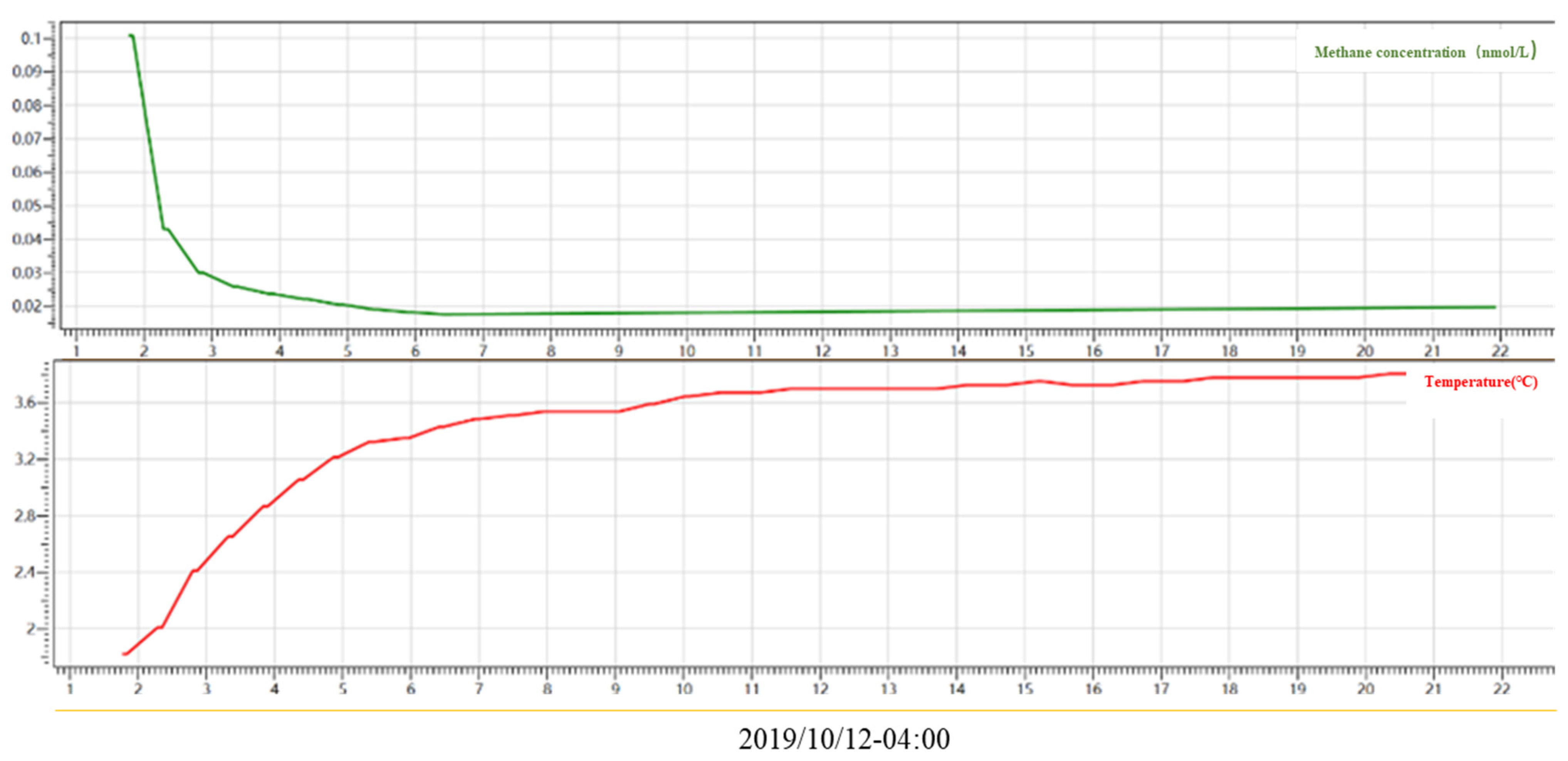
(2) The communication sampling frequency at a water depth of 500 m was set as 3 s, and the sampling time was 2–3 min. The test results showed that the communication was normal and the data were successfully received.As shown in
Figure 6 and
Figure 7.
(3) The operating frequency was 30 s at a water depth of 1250 m, and the test time was 10–20 min. The test results showed that the communication was normal, and the data were successfully received. As shown in
Figure 8,
Figure 9 and
Figure 10.
The deep-sea environment is subject to less interference, and the sensor was preheated during the system-lowering process, which achieved the optimal state of sensor use. Therefore, the data received by the sensor tended to be flat as the depth increased from 500 m to 1250 m.
5. Results and Discussion
(1) A wellhead overflow monitoring system for the open-circuit drilling of offshore natural gas was designed, which was mainly used to monitor the methane content of the drilling fluid return fluid and surrounding areas. The as-designed system is composed of an underwater acoustic communication receiving part and an underwater self-contained methane monitoring part. In actual use, the underwater self-contained methane monitoring system was arranged around the mining wellhead to monitor the overflow status and content of methane gas at the wellhead in real time. Compared with the current gas logging technology (measurement while drilling) used in the oil and gas exploration drilling stage, the system realized the monitoring of methane content in the process of drilling, casing running, cementing, completion and fracturing of marine natural gas hydrate when it was placed at the production wellhead.
(2) The system included a wellhead suction filter device with forward and back flushing circuits, which avoided the blockage of the sensor detection module by mud return fluid and improved the detection effect to a certain extent. In addition, the sensor needs to be preheated to achieve optimal performance.
(3) This system updated the method of monitoring methane in the drilling overflow of marine gas hydrate. The drilling mud return fluid was pumped into the measurement system to detect the methane content, and the collected data were transmitted back to the shore-based system through acoustic communication, which effectively avoided the loss of methane in the mud return fluid in the process of collection and transportation, thus enhancing the monitoring accuracy of the system to a certain extent.
(4) The stability of the system and the reliability of data reception under a real environment were further verified through 500 m and 1250 m sea trials, which provided technical reserves for wellhead overflow monitoring and early warning in the process of gas hydrate exploitation.
Author Contributions
Analysis and investigation, C.Z.; writing—review and editing, C.Z.; methodology, C.Z. and J.L.; writing—original draft preparation, D.K. All authors have read and agreed to the published version of the manuscript.
Funding
This research was jointly supported by the Key-Area Research and Development Program of Guangdong Province (2020B1111030003) and the Geological Survey Projects of China Geological Survey (DD20221700, DD20221706).
Conflicts of Interest
The authors declare no conflict of interest.
References
- Fang, Y.X.; Li, M.B.; Jin, X.L.; Shentu, H.G. Character analysis of the marine gas hydrate stability zone. Mar. Geol. Quat. Geol. 2001, 21, 103–106. [Google Scholar]
- Li, J.; Zhang, C.; Wu, Z.; Zhang, G.; Gao, Q.; Liu, K.; Cheng, X. Can low hydration heat cement prevent the decomposition of natural gas hydrate under high pressure and low temperature? J. Nat. Gas Sci. Eng. 2022, 97, 104347. [Google Scholar] [CrossRef]
- Rakibul, I.; Faisal, K. Real time risk analysis of kick detection: Testing and Validation. Reliab. Eng. Syst. Saf. 2017, 161, 25–37. [Google Scholar]
- Ali, K.V. Early kick detection and well control decision-making for managed pressure drilling automation. J. Nat. Gas Sci. Eng. 2015, 27, 354–366. [Google Scholar]
- Wei, L.; Yang, X.; Xi, C.; Hong, C.; Yumin, L.; Xueqing, L. Research and application of downhole blowout prevention system while drilling: A review. J. Pet. Sci. Eng. 2019, 188, 106882. [Google Scholar] [CrossRef]
- Chen, P.; Ma, T.S. Research status of early monitoring technology for deepwater drilling overflow. Acta Pet. Sin. 2014, 35, 602–612. [Google Scholar]
- Liu, Z.; Ma, Q.; Cai, B.; Liu, Y.; Zheng, C. Risk assessment on deepwater drilling well control based on dynamic bayesian network. Proc. Saf. Environ. Prot. 2021, 149, 643–654. [Google Scholar] [CrossRef]
- Morley, J.; Heidler, R. Field testing of an new nuclear magnetic resonance logging while drilling tool. In Proceedings of the SPE Annual Technical Conference and Exhibition, San Antonio, TX, USA, 29 September–2 October 2002. [Google Scholar]
- Krishna, S.; Ridha, S.; Campbell, S.; Ilyas, S.U.; Dzulkarnain, I.; Abdurrahman, M. Experimental evaluation of surge/swab pressure in varying annular eccentricities using non-newtonian fluid under couette-poiseuille flow for drilling applications. J. Pet. Sci. Eng. 2021, 206, 108982. [Google Scholar] [CrossRef]
- Gandelman, R.A.; Martins, A.L.; Teixeira, G.T.; Waldmann, A.T.A.; Rezende, M.S.C.; Aragao, A.F.L. A comprehensive methodology to avoid and remediate drilling problems by real-time pwd data interpretation. In Proceedings of the SPE Annual Technical Conference and Exhibition, New Orleans, LA, USA, 4–7 October 2009. [Google Scholar]
- Charlez, P.A.; Easton, M.; Morrice, G.; Tardy, P. Validation of advanced hydraulic modeling using pwd data. In Proceedings of the Offshore Technology Conference, Houston, TX, USA, 4–7 May 1998. [Google Scholar]
- Harris, M.; Byrd, D.M.; Archibald, M.; Naupari, C.E.; Bittar, M.S.; Chemali, R.E. Real-time decisions with improved confidence using azimuthal deep resistivity and at-bit gamma imaging while drilling. In Proceedings of the SPE Offshore Europe Oil and Gas Conference and Exhibition, Aberdeen, UK, 8–11 September 2009. [Google Scholar]
- Okoli, U.; Schrader, H. Using LWD Tools to Enhance Drilling Operations: A Case Study. In Proceedings of the Nigeria Annual International Conference and Exhibition, Lagos, Nigeria, 6–8 August 2012. [Google Scholar]
- Zhou, Q.; Zhao, H.; Zhan, H.; Zhang, H.; Lu, C. The application of ultrasonic based on doppler effect used in early kick detection for deep water drilling. In Proceedings of the International Conference on Communications, Budapest, Hungary, 9–13 June 2013. [Google Scholar]
- Zhou, K.; Chen, G. Analysis of Oil Spill Hyperspectral Data Based on Spectral Characteristics; “The Belt and Road” Strategy and Marine Scientific and Technological Innovation; Oceanographic Society of China: Beijing, China, 2015. [Google Scholar]
- Yongshou, D.A.I.; Weijie, Y.U.E.; Weifeng, S.U.N. Online monitoring and warning system for early kick foreboding on three high wells. J. China Univ. Pet. (Ed. Nat. Sci.) 2015, 39, 188–194. [Google Scholar]
- Li, J.W.; Liu, G.H.; Li, J. Study on kick detection methods during U-tubing effect in dual gradient drilling. Drill. Prod. Technol. 2016, 39, 19–22. [Google Scholar]
- Wu, X.; Wan, F.; Chen, Z.; Han, L.; Li, Z. Drilling and completion technologies for deep carbonate rocks in the sichuan basin: Practices and prospects. Nat. Gas Ind. B 2020, 7, 547–556. [Google Scholar] [CrossRef]
- Nayeem, A.A.; Venkatesan, R.; Khan, F. Monitoring of down-hole parameters for early kick detection. J. Loss Prev. Proc. Ind. 2015, 40, 43–54. [Google Scholar] [CrossRef]
- Kamyab, M.; Shadizadeh, S.R.; Jazayeri-rad, H.; Dinarvand, N. Early kick detection using real time data analysis with dynamic neural network: A case study in iranian oil fields. In Proceedings of the SPE Nigeria Annual International Conference and Exhibition, Tinapa, Calabar, Nigeria, 31 July–7 August 2010. [Google Scholar]
- Yuan, J.L.; Fang, B.T.; Xing, X.S.; Gen, L.J.; Yin, Z.; Wang, Y. Real-time early warning of drilling overflow based on naïve Bayes algorithm. Oil Drill. Prod. Technol. 2021, 43, 455–460. (In Chinese) [Google Scholar]
- Dong, Y.F.; Luo, W.Z.; Liang, Q.Y.; Qiu, H.L.; Ren, C.; Yan, R.; Lin, J.Q. A developed bottom-supported submersible buoyant system and its testing application to a natural gas hydrate area. Mar. Geol. Quat. Geol. 2017, 37, 195–203. (In Chinese) [Google Scholar]
- Zhong, C.; Liang, Q.Y.; Guo, B.B.; Wu, X.M.; Dong, Y.F.; Yang, L.; Xiao, X.; Zhang, T.T.; Su, D.Y.; Wu, X.Y. An Open-Circuit Drilling Wellhead Methane Logging System. Chinese Patent ZL202011242750.1, 17 June 2022. (In Chinese). [Google Scholar]
| Publisher’s Note: MDPI stays neutral with regard to jurisdictional claims in published maps and institutional affiliations. |
© 2022 by the authors. Licensee MDPI, Basel, Switzerland. This article is an open access article distributed under the terms and conditions of the Creative Commons Attribution (CC BY) license (https://creativecommons.org/licenses/by/4.0/).


