Review

Review of Closed SCO2 and Semi-Closed Oxy–Fuel Combustion Power Cycles for Multi-Scale Power Generation in Terms of Energy, Ecology and Economic Efficiency

Moscow Power Engineering Institute, National Research University, Krasnokazarmen-naya, 14, 111250 Moscow, Russia
*
Author to whom correspondence should be addressed.
Energies 2022, 15(23), 9226; https://doi.org/10.3390/en15239226
Submission received: 1 November 2022 / Revised: 30 November 2022 / Accepted: 2 December 2022 / Published: 5 December 2022

Abstract

:
Today, with the increases in organic fuel prices and growing legislative restrictions aimed at increasing environmental safety and reducing our carbon footprint, the task of increasing thermal power plant efficiency is becoming more and more topical. Transforming combusting fuel thermal energy into electric power more efficiently will allow the reduction of the fuel cost fraction in the cost structure and decrease harmful emissions, especially greenhouse gases, as less fuel will be consumed. There are traditional ways of improving thermal power plant energy efficiency: increasing turbine inlet temperature and utilizing exhaust heat. An alternative way to improve energy efficiency is the use of supercritical CO2 power cycles, which have a number of advantages over traditional ones due to carbon dioxide’s thermophysical properties. In particular, the use of carbon dioxide allows increasing efficiency by reducing compression and friction losses in the wheel spaces of the turbines; in addition, it is known that CO2 turbomachinery has smaller dimensions compared to traditional steam and gas turbines of similar capacity. Furthermore, semi-closed oxy–fuel combustion power cycles can reduce greenhouse gases emissions by many times; at the same time, they have characteristics of efficiency and specific capital costs comparable with traditional cycles. Given the high volatility of fuel prices, as well as the rising prices of carbon dioxide emission allowances, changes in efficiency, capital costs and specific greenhouse gas emissions can lead to a change in the cost of electricity generation. In this paper, key closed and semi-closed supercritical CO2 combustion power cycles and their promising modifications are considered from the point of view of energy, economic and environmental efficiency; the cycles that are optimal in terms of technical and economic characteristics are identified among those considered.

1. Introduction

Organic and nuclear fuels are the main sources of thermal energy in the world. Steam turbine, gas turbine and steam-gas cycles utilizing water vapor and air as a working fluid are widely used to convert thermal energy into electric power. Under conditions of rising energy prices and tightening requirements for emissions of harmful substances, an urgent task is to increase the efficiency of converting thermal energy into electric power in order to reduce fuel consumption.
According to Carnot’s theorem, the maximum possible efficiency of a heat cycle depends on the temperature of the “heater” and the temperature of the “cooler”—the greater the first and the lower the second, the more efficient the heat machine is.
For traditional energy cycles, the main way to increase efficiency is to increase the temperature and pressure of the working fluid at the turbine input, that is, increase the “heater” temperature. Thus, transition from supercritical steam parameters (540 °C, 24 MPa) to ultra-supercritical (720 °C, 35 MPa) leads to an increase in the net efficiency of a steam turbine power unit of 5–6%. In advanced engineering enterprises using gas turbine and steam-gas cycles, working fluid temperature at the turbine input exceeds 1600 °C, and the net efficiency of the most efficient steam-gas plants is 62–64% [1].
However, an increase in the working fluid temperature leads to an increase in capital costs for the construction of power units, since elevated temperatures require expensive heat-resistant materials, and an increase in pressure requires either more mechanically durable materials or an increase in wall thickness for existing materials, which requires more metal for power plant construction.
In terms of environmental safety, an increase in temperatures during fuel combustion in the air leads to intensification of the oxidation of the main component of air—nitrogen (over 75% by weight)—which leads to an increase in emissions of nitrogen oxide (NOx), which is one of the most dangerous pollutants for the environment. To reduce NOx emissions, specialized low-emission combustion chambers and exhaust gas purification are used, while the introduction of new elements or the complication of existing structures also negatively affects the main equipment cost [2].
Another way to increase thermal plant efficiency is through waste heat recovery (WHR), that is, reducing the temperature of the “cooler”. Heat is utilized by introducing an additional low-temperature cycle which uses waste heat as a source of thermal energy. In this case, the use of expensive, heat-resistant alloys is not required. However, due to the low thermal potential of the waste heat, the waste heat recovery units have extremely low efficiency (not more than 5–6%), which gives an increase in the power unit efficiency of no more than 2–3%; for that, massive metal-intensive heat exchangers with a large heat exchange area, which increase the capital costs of the main equipment, are used. Thus, in WHR, specific capital costs increase due to the increase in the total metal consumption of the power unit [3,4,5].
Using low-boiling organic coolant can increase the thermodynamic efficiency of cycles. In study [6], a Brayton recompression cycle with pure CO2 and with binary mixture CO2–C7H8 was considered, and the thermal efficiency of the second one was 14.5% greater than the first one. On the other hand, low-boiling organic coolants have a high cost and are often dangerous for the environment. In particular, most freons are the strongest greenhouse gases [7,8]. Thus, HFC 134a freon has a global warming potential (GWP) of 1300, that is, the emission of 1 kg of freon is equivalent to 1300 kg of carbon dioxide. It is important to note that freons are emitted even when they are used in closed cycles due to vaporization through seals. Thus, an important problem of waste heat utilization power cycles is revealed by carbon footprint analysis taking into account the GWP of various fluids. In study [9], the organic Rankine cycle (ORC) was considered for various freons, and the difference between the maximum environmental impact fluid (R114) and the minimal environmental impact was more than 50%.
An alternative way to improve the energy efficiency of thermal power plants (TPP) and to reduce plant cost is through the use of supercritical carbon dioxide as a coolant. This direction began to develop in the middle of the last century; today, dozens of CO2 power cycles and their modifications are known. Examples of implemented industrial power plants are nuclear power plants based on gas-cooled nuclear reactors such as the Magnox and advanced gas-cooled reactor (AGR).
The attractiveness of the transition to CO2 power cycles in order to increase the energy and economic efficiency of TPP plants is primarily due to the thermal and physical properties of supercritical carbon dioxide.
Supercritical carbon dioxide (SCO2) is characterized by relatively low critical parameters (30.98 °C and 7.38 MPa), which make it possible to compress the working fluid near the saturation line and to significantly reduce the compressor work while also reducing the temperature of the heat removal from the cycle. In turn, reducing the temperature of the heat-recovering cycle makes it possible to increase the thermodynamic efficiency. In addition, carbon dioxide has a relatively low aggressiveness compared to water and exhibits corrosion activity only in the presence of moisture in the gas or in the presence of a film of water on the metal surface.
The thermophysical properties of water, air and supercritical carbon dioxide heat carriers, presented in Table 1 within the typical parameters of modern gas turbine and steam turbine plants, indicate the advantages of using carbon dioxide as a working fluid. High carbon dioxide density at the parameter values typical for the input and output of a carbon dioxide turbine determines its low weight and size characteristics compared to steam and gas turbines with a similar working flow.
Furthermore, the values of the dynamic viscosity coefficient of carbon dioxide at the turbine input are lower or comparable to those of air and water, which indicates that blade friction energy losses in the turbine utilizing supercritical carbon dioxide do not exceed the losses in steam and gas turbines. Thus, the transition to supercritical carbon dioxide is the prospective direction in the development of closed power cycles such as the Brayton cycle and the Rankine cycle.
On the other hand, an important direction in the development of carbon dioxide cycles is towards semi-closed oxy–fuel combustion power cycles with internal combustion. Semi-closed oxy–fuel combustion cycles can reduce carbon dioxide emissions due to the sequestration of CO2 from the exhaust of the turbine, and these types of cycles have characteristics of efficiency and specific capital costs comparable with traditional cycles [10].
The potential problems of using supercritical carbon dioxide power cycles and semi-closed oxy–fuel combustion cycles are:
  • The problem of coolant leakage, which can increase the carbon footprint of a plant;
  • The need for the compression of carbon dioxide in the near-critical region near the saturation boundary of the coolant (fraught with sharp jumps in thermophysical properties up to gravitational effects on the inlet blade of the compressor);
  • The large heating surfaces required by the carbon dioxide heat exchangers because of the large capacity of the regenerators, which generate increasing capital costs;
  • The low critical temperature of CO2, which creates the need for a low-temperature cold source (10–15 °C) for closed cycles, especially cycles with condensation.
Despite the differences in the schemes, the principle of operation and the regime parameters of the working fluid, both for closed SCO2 cycles and semi-closed oxy–fuel combustion cycles, both aim to increase the energy and economic efficiency of energy generation. In the case of closed SCO2 cycles, the increase in the techno-economic characteristics is achieved through the downsizing of the main equipment and significantly increases cycle efficiency. In the case of semi-closed oxy–fuel combustion cycles, the increase in techno-economic characteristics is achieved through the almost complete absence of carbon dioxide emissions, which leads to minimal expenses related to the purchase of emissions quotas. Thus, the two types of cycles can improve the technical and economic indicators of thermal power plants in different ways.
The purpose of this paper is to generalize and systematize the data presented in the scientific literature regarding thermodynamic cycles utilizing supercritical carbon dioxide, as well as to identify the optimal technical solutions for the sustainable development of thermal power engineering through a systematic comparative analysis of various carbon dioxide energy cycles among themselves and through comparing them with traditional, high-efficiency TPP plants with regard to key technical and economic characteristics.

2. Closed SCO2 Cycles

Closed thermodynamic cycles are characterized by the supply of heat from an external source—a boiler or nuclear reactor. Burning reactions do not occur in the working body itself. On the one hand, this approach expands the range of thermal energy sources—organic fuels and nuclear reactions, WHR or solar energy collectors can be used. On the other hand, this approach leads to an increase in the equipment cost since massive metal-intensive heat exchange devices are required for heat transfer—boilers, heat recovery boilers, etc.
To date, all closed cycles utilizing supercritical CO2 can be divided into two large groups:
  • Cycles without condensation, with the working fluid compression by a compressor (Brayton cycles);
  • Cycles with condensation, with the working fluid compression by a pump (Rankine cycles).
These cycles have a large number of modifications and arrangements with various heat energy sources and have different power, efficiency and capital intensity. In this paper, Brayton and Rankine cycles utilizing supercritical CO2 and their main modifications described within the literature are considered.

2.1. Closed SCO2 Brayton Cycles

The Brayton cycle with supercritical CO2 was mentioned for the first time in 1948. Sulzer Bros patented the Brayton cycle with partial condensation of carbon dioxide. After that, CO2 power cycles aroused the interest of power plant researchers and developers. Research in this area has been conducted in many countries. In the Soviet Union, D. Gokhshtein and G. Verkhivker were engaged in the development of CO2 power cycles [11] in 1969; in one of their works, they presented a thermal scheme of a nuclear power plant with carbon dioxide as a coolant and working fluid (Figure 1).
In the first loop, the reactor is cooled by carbon dioxide (3–4), which then expands from 3 MPa (675 °C) to 1 MPa (539 °C) in a turbine to generate electric power (4–5). Then, the hot gases pass sequentially through the first regenerative heater (5–6), in which they give off heat to the second cycle, thereby ensuring its initial temperature of 509 °C. Then, exhaust CO2 gases enter the second regenerative heater (6–7), where the working fluid of the first loop compressed in the compressor is heated from 173 to 320 °C. In the third regenerative heater (7–1), carbon dioxide also gives heat to the second loop, after which, it is compressed in the compressor and passes sequentially through the second regenerative heater and the reactor back into the turbine.
In the second loop, CO2 is also used as a working fluid. In a gas turbine, carbon dioxide expands from 23.5 (509 °C) to 6 MPa (355 °C) (12–13) and then it passes sequentially through two regenerative heaters (13–15), the cold source (15–8), pump (8–9) and the regenerator system (9–12), in which the coolant temperature rises to the initial value.
The authors found that the net electrical efficiency of the considered cycle is 44.5%, 3% higher than that of the same cycle utilizing water. This scheme’s disadvantage is a 71% larger heat exchange area and, as a result, greater metal consumption by the main equipment.
First, CO2 power cycles became a foundation for numerous subsequent studies, the main results of which were the development of the following five cycles based on supercritical carbon dioxide:
  • Supercritical CO2 Brayton cycle with regeneration [12,13];
  • Supercritical CO2 Brayton cycle with reheating [12,14];
  • Supercritical CO2 Brayton cycle with precooling [12];
  • Supercritical CO2 Brayton cycle with partial cooling [12,15];
  • Supercritical CO2 Brayton cycle with recompression [12];
  • Supercritical CO2 Brayton cascade cycle [16].
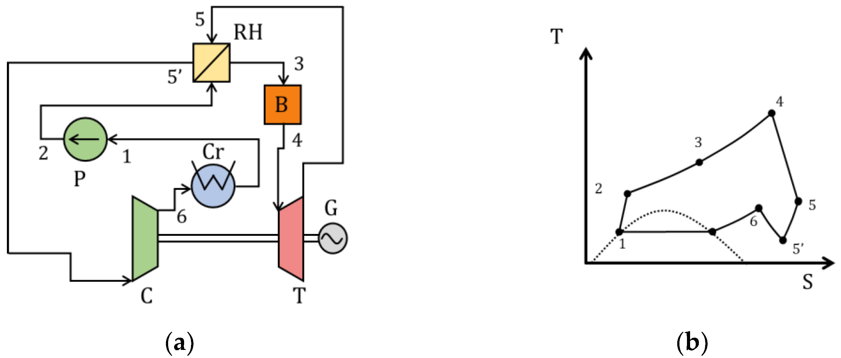
The simplest cycle utilizing supercritical CO2 is the closed Brayton cycle with exhaust gas heat regeneration (Figure 2a). The compressor receives recirculating carbon dioxide (1–2), which, after compression, is sent to the regenerator for heating (2–3). The heated flow of the working fluid enters the reactor (3–4) and further increases in temperature. Next, the supercritical working fluid is sent to a gas turbine (4–5), which rotates the electric generator. After expansion, the turbine exhaust gases enter the regenerator (5–6) to transfer heat to the working fluid compressed in the compressor. Then, before being fed to the compressor, the cooled CO2 stream is directed to a cold source (precooler) (6–1), where additional cooling of the coolant occurs. Figure 2b shows a T–S diagram of this cycle.
At an initial temperature of 550 °C, the compressor inlet temperature is 32 °C, and, at a compressor output pressure of 25 MPa, the thermal efficiency is about 40%. Results of the study on the effect of the initial pressure at the turbine input on the efficiency of the Brayton supercritical cycle showed that the pressure increase of 2 MPa in the range of 13.8–27.6 MPa leads to an increase in efficiency of 0.71% [13], and an increase in initial temperature of 150 °C is accompanied by an increase in thermal efficiency of 5.5%.
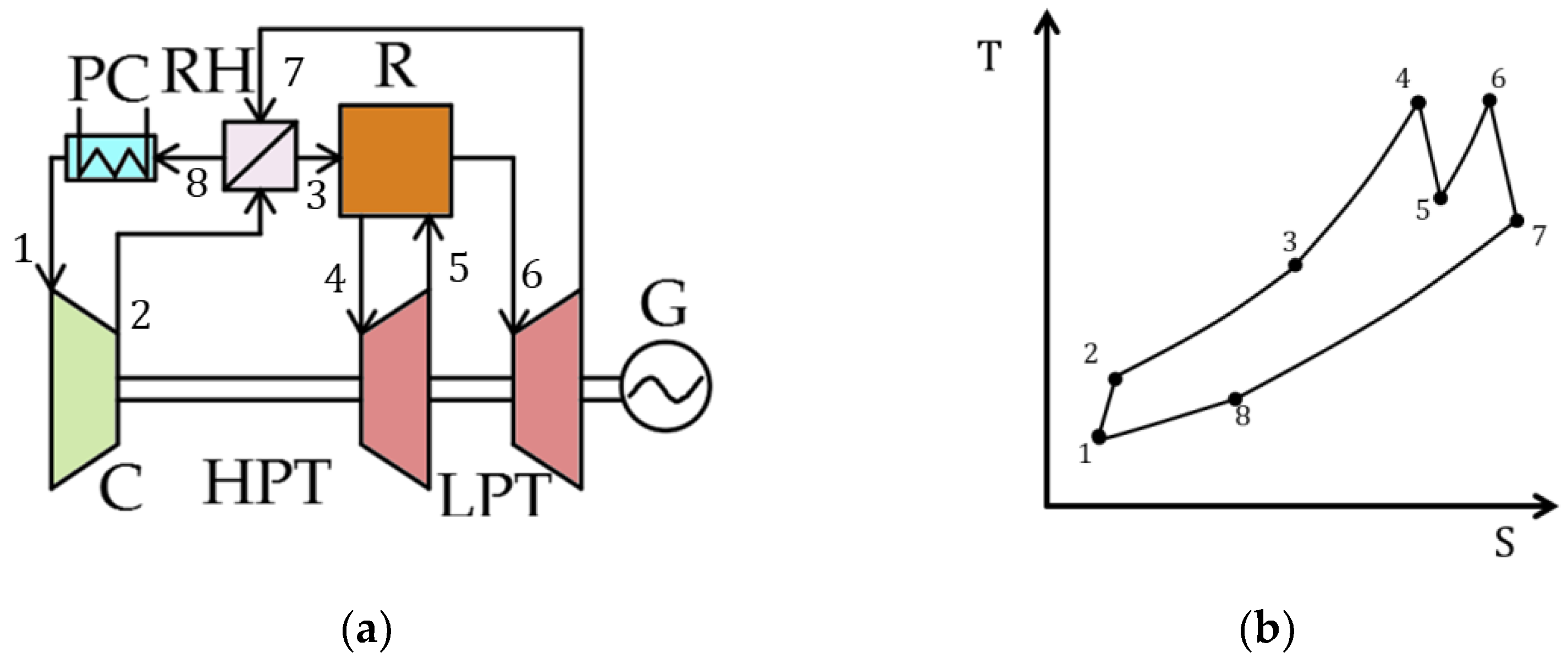
It is possible to increase the efficiency of the closed supercritical Brayton cycle based on CO2 by using intermediate overheating. The thermal scheme presented in Figure 3a differs from the previous one (Figure 2a) by the presence of a second working fluid entry into the reactor, that is, carbon dioxide is also compressed in the compressor and then sent to the regenerator, where it is heated due to the heat of the working fluid at the turbine output. After that, the carbon dioxide stream is sent to the reactor to increase the working fluid temperature (5–6) to the initial cycle value and then enters the gas turbine (6–7). Next, expansion occurs in the wheel space of the high-pressure turbine, after which, the working fluid enters the reactor again for reheating. Figure 3b shows a T–S diagram of this cycle.
Results of the thermodynamic study presented in [14] revealed that the largest increase in efficiency is achieved when the expansion degree under pressure in the high-pressure turbine (HPT) is equal to that in the low-pressure turbine (LPT). With initial cycle parameters of 550 °C and 25 MPa, and a turbine exhaust pressure of 7.5 MPa, the cycle efficiency is about 41.5%.
However, it should be borne in mind that the introduction of additional superheaters will certainly be accompanied by pressure losses. An increase in pressure losses of 10% in the range of 0–250 kPa will lead to a decrease in power plant efficiency of about 0.11%. With a further increase in pressure losses in the heater, the use of repeated overheating of the working fluid is impractical, since this leads to a decrease in the efficiency of the cycle.
Implementation of a second intermediate superheater makes it possible to increase the efficiency of the Brayton cycle based on supercritical CO2 by another 0.20–0.26% with pressure losses in the heater not exceeding 125 kPa.
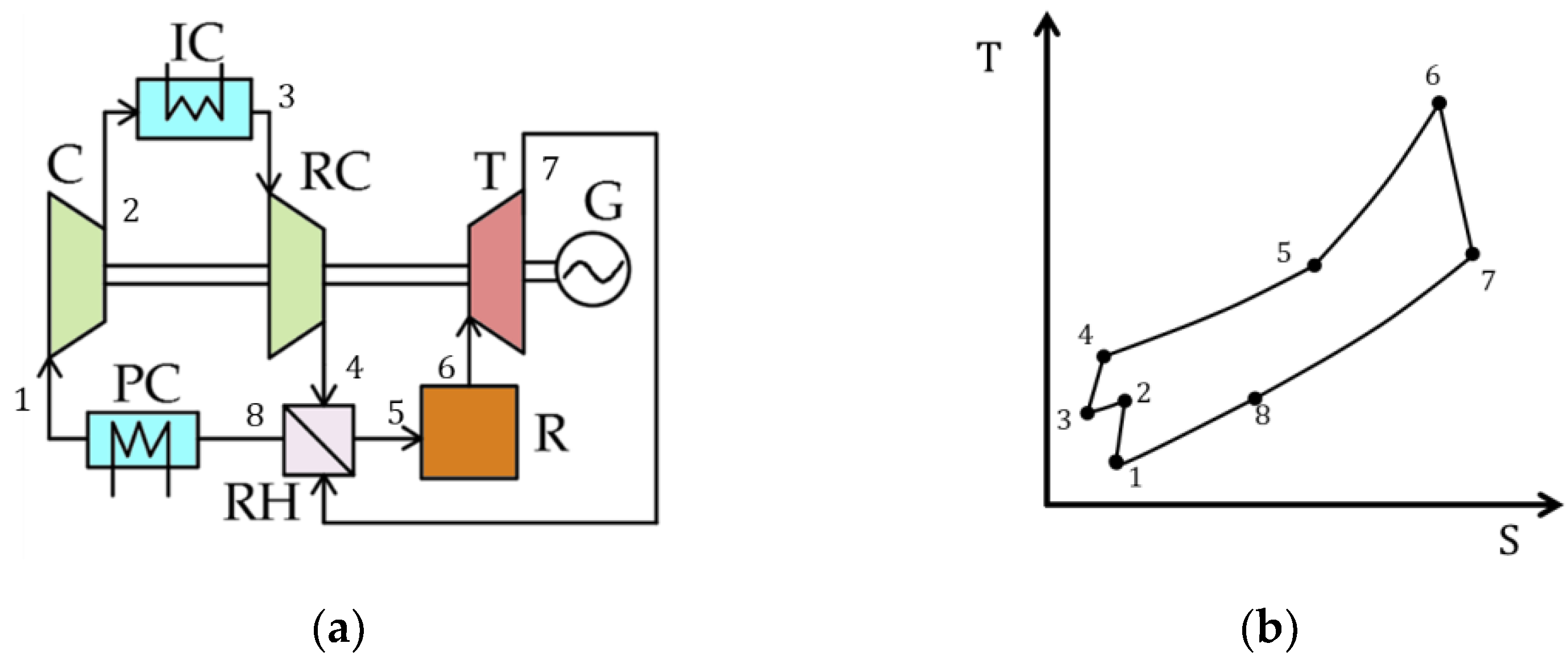
Another way to increase the efficiency of the simplest Brayton cycle based on supercritical CO2 is the introduction of intermediate cooling, which helps to reduce compressor energy consumption (Figure 4). In contrast to the simple Brayton cycle with regeneration (Figure 2a), in this case, two low- (1–2) and high-pressure (3–4) compressors (RC) and an intermediate cooler (2–3) are used.
A maximum increase in the cycle thermodynamic efficiency is achieved when the second compressor compression ratio is 1.5–1.9 times greater than that of the first one. In this case, the efficiency of the Brayton cycle based on supercritical CO2 increases by 0.8%.
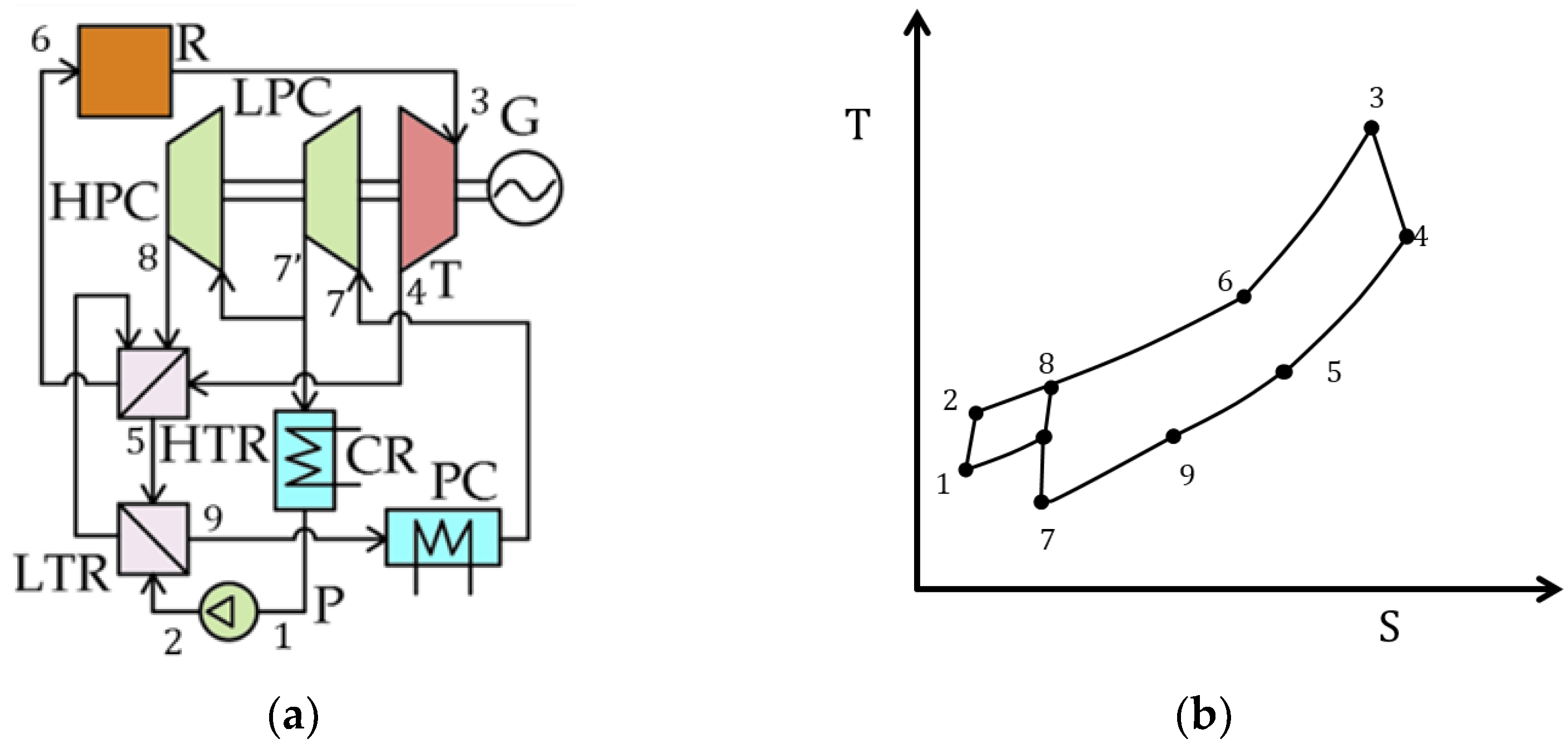
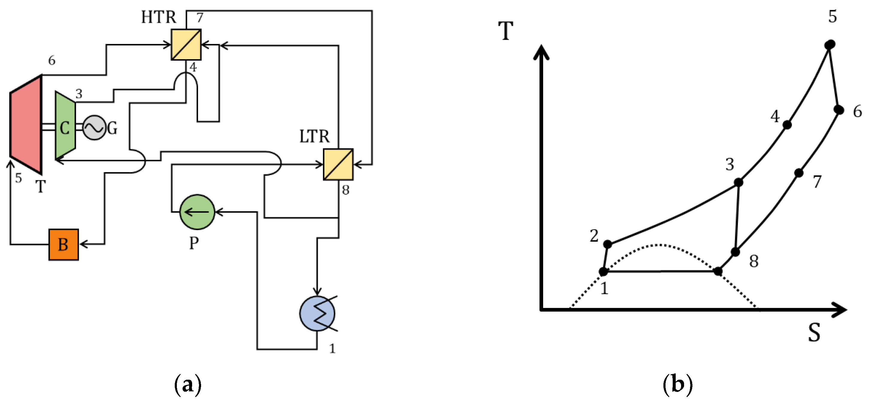
In addition to the above schemes, in 1968, G. Angelino proposed another option to increase the efficiency of the supercritical CO2 Brayton cycle—a cycle with partial cooling [15]. The scheme presented in Figure 5 differs from the Brayton cycle based on supercritical CO2 with regeneration by the presence of high-temperature and low-temperature heat exchangers, a condenser, pump (compressor) and a recompression compressor.
The working fluid is compressed in the compressor (7–7′) and then is divided into two streams; the first stream is sent to the recompression compressor (RC) (7′–8), and the second is cooled in the condenser (CR) (7′–1) and then is also compressed in the compressor (pump) (1–2). CO2 compressed in the pump is first heated in a low-temperature heat exchanger (LTR) by utilizing exhaust gas heat (2–8) and then it is mixed with the first stream of carbon dioxide in a high-temperature heat exchanger (HTR) (8–6). After that, the entire volume of the heated working fluid is sent to the reactor, where it is heated to the initial temperature of the cycle (6–3). Such a solution makes it possible to increase the regeneration system efficiency by means of a heat exchanger operation at different pressures.
At an initial temperature of 550 °C and a pressure of 25 MPa, the thermal efficiency of the Brayton cycle based on supercritical CO2 with partial cooling is 44.8%. The main disadvantage of this cycle is associated with the low critical temperature of CO2 (30.98 °C), as condensing CO2 cycles require an available supply of cooling water at a temperature of 10–15 °C, which is not available in all regions worldwide all year.
Additionally, Angelino proposed a simplified version of the cycle described above—a supercritical CO2 Brayton cycle with recompression (Figure 6). Unlike the cycle with partial cooling, there is no pump or cooler in this scheme.
The carbon dioxide stream is separated before the precooler, then the first part of the stream is cooled (8–1) and enters the main compressor (1–2) for compression to the initial pressure, and the second part of the stream immediately enters the recompression compressor (8–3), where the working fluid is also compressed to the initial pressure of the cycle. After the main compressor, the compressed CO2 enters a low-temperature heat exchanger (2–3), where, due to the regeneration of the exhaust gas heat, carbon dioxide is heated to the same temperature as the second CO2 stream after compression in the recompressor.
This arrangement of the thermal circuit allows the problem of the relatively low efficiency of waste gas heat regeneration associated with the significant difference in specific heat capacity between hot and cold flows in the regenerator, which is characteristic of the supercritical CO2 Brayton cycle with regeneration, to be solved. In other words, the separation of compressible flows and the introduction of a low-temperature and high-temperature heat exchanger allow increasing efficiency of exhaust gas heat regeneration and reduce losses in the cold source. As a result of this technical solution application, the thermal efficiency of the Brayton cycle based on supercritical carbon dioxide increases to 46%.
The Brayton cascade cycle was designed to utilize exhaust gas waste heat in the gas turbine plants, and it has a large number of heat exchangers. In [16], various configurations of cascade Brayton cycles were considered, the most promising of which, according to the author, is a cascade cycle with double overheating, which has an efficiency of 32.6% when the temperature at the turbine input is about 500 °C. Figure 7 shows a scheme and T–S diagram of the cascade Brayton cycle.
Brayton cycles using supercritical carbon dioxide as a coolant can also be used as cycles for waste heat recovery. In [17], Brayton cycles for waste heat regeneration were considered, in particular:
  • Supercritical CO2 Brayton simple cycle;
  • Supercritical CO2 regenerative Brayton cycle;
  • Supercritical CO2 regenerative Brayton cycle with recompression;
  • Supercritical CO2 Brayton cascade cycle.
When the temperature at the turbine input is equal to 200–600 °C, these cycles demonstrate an efficiency of 10 to 40%, depending on the scheme.
In [18], the joint use of the Kalina cycle and a simple supercritical Brayton cycle for the WHR of a diesel engine was considered. At a heater temperature of 268 °C, the system had an efficiency of 16% and allowed the generation of 242 kW of electrical power.

2.2. Closed SCO2 Rankine Cycles

The fundamental difference between supercritical Rankine CO2 power cycles and the Brayton cycles is the presence of carbon dioxide condensation after expansion in the turbine. Supercritical CO2 power cycles with condensation were considered for the first time in papers by Angelino in 1968 [13]. The advantage of Rankine cycles over Brayton cycles is the reduced work required for compression with a pump compared to that required for compression with a compressor. The main disadvantage is the need for a cold source with a temperature 10–15 °C because of the low critical temperature of CO2. The most effective cycle of those presented in Angelino’s papers is considered to be the Rankine cycle with recompression, which has a calculated theoretical efficiency 43% at a temperature at the turbine input of 550 °C.
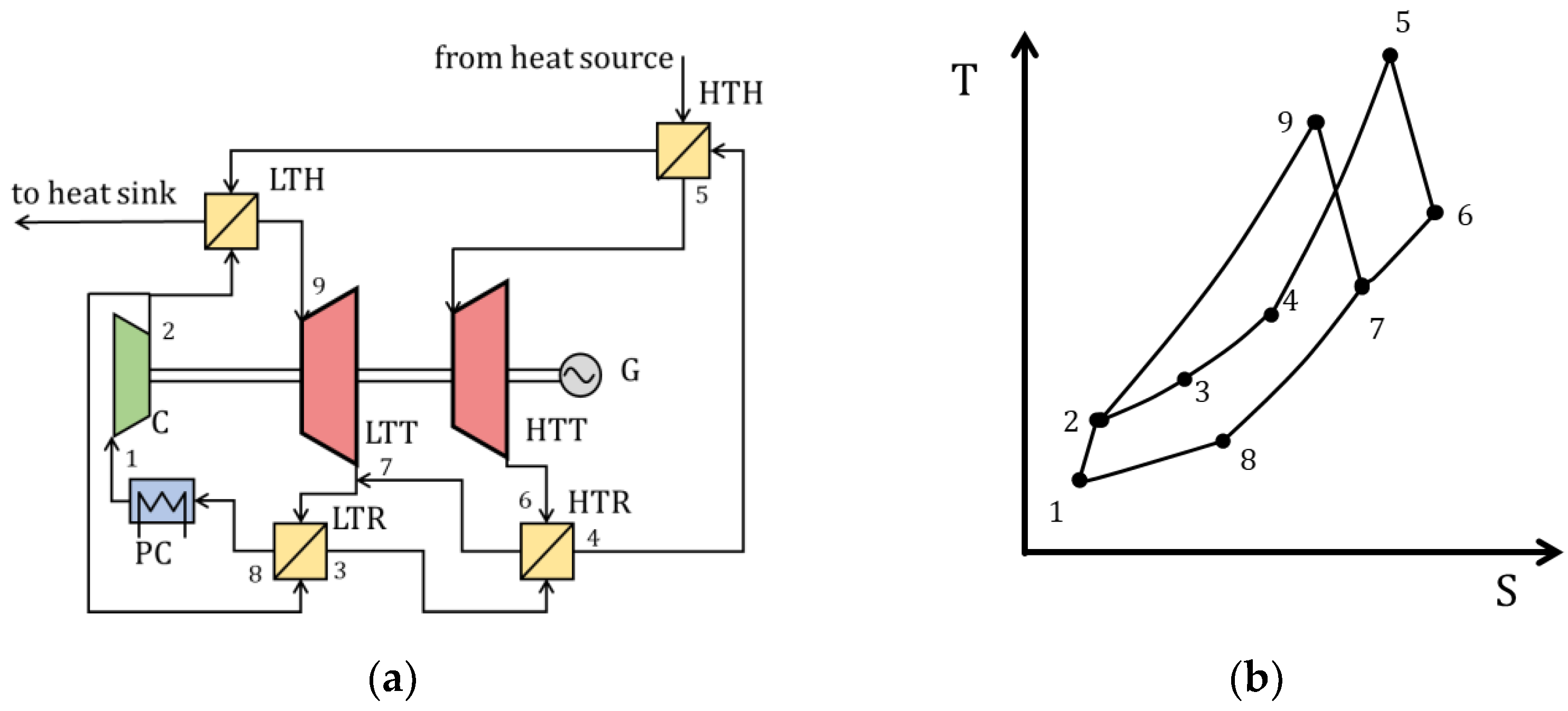
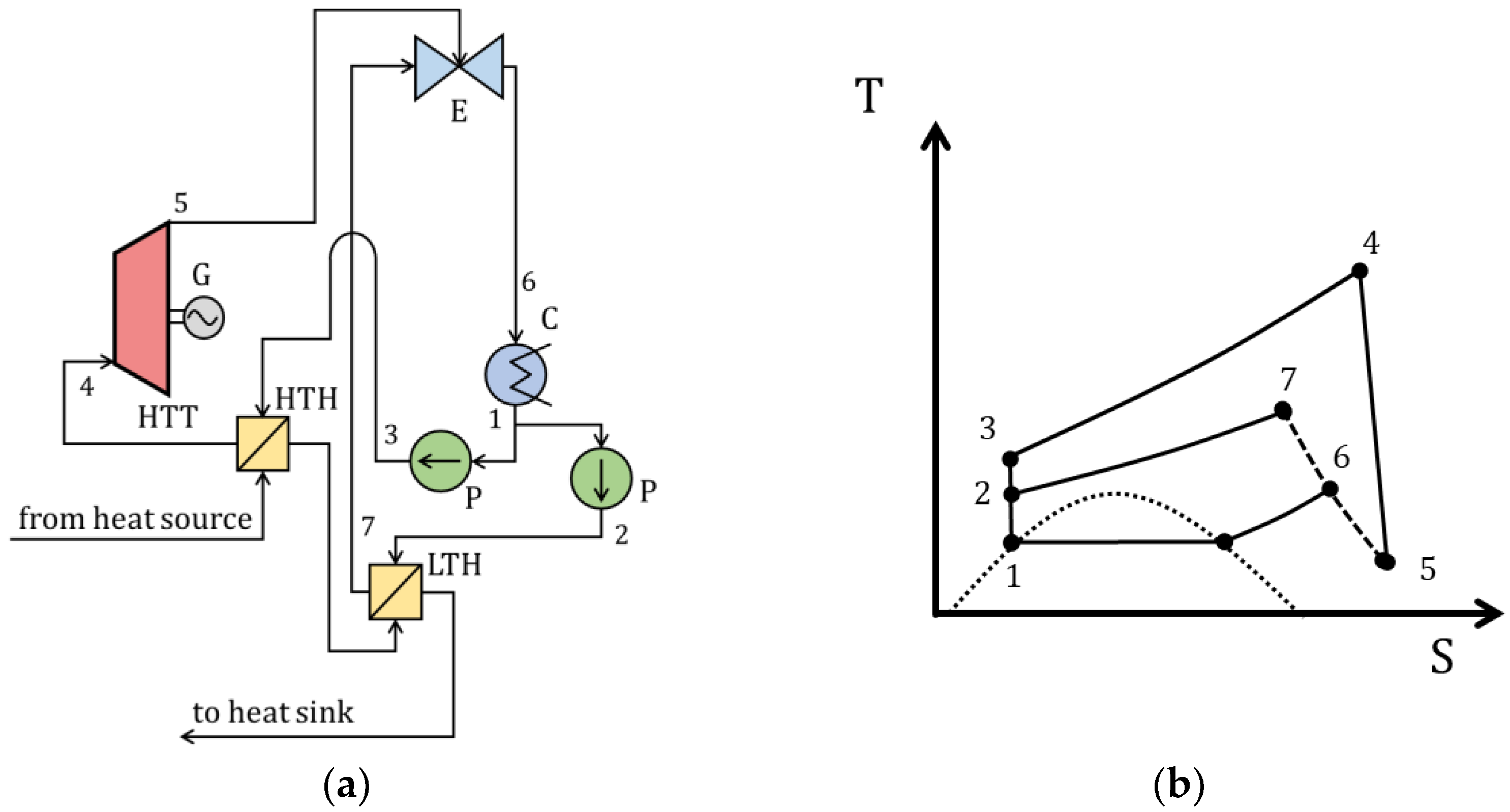
The schematic and T–S diagram of the Rankine cycle with recompression are shown in Figure 8. In this cycle, carbon dioxide expands in the turbine after the heater (5–6), then it is cooled in the high-temperature regenerative heat exchanger (6–7), after which, it is cooled in the low-temperature regenerative heat exchanger (7–8). Further, part of the flow is directed to the condenser (8–1), after which, condensate is compressed by a pump (1–2) and fed through a low-temperature regenerator (2–3) to a high-temperature regenerator (3–4). Another part of the flow is immediately sent to the compressor for compression (8–3) and then it enters the high-temperature regenerator (3–4), where it is mixed with the first part, heated and sent to the heater (4–5).
At the same turbine inlet temperature, supercritical carbon dioxide power plants operating with the use of the Rankine cycle have lower efficiency and higher metal consumption compared to those operating with the Brayton cycles. However, the implementation of cooling during the working fluid condensation of the low-pressure cycle allows efficient cooling at a low temperature with a relatively small heat exchange area. Thus, Rankine cycles can be used for WHR, including low-potential WHR.
At present, the efficiency of a number of modifications of the supercritical carbon dioxide Rankine cycle for waste heat recovery is being considered, including the efficiency of a low-thermal-potential-heat modification.
In paper [14], the following Rankine cycles based on supercritical carbon dioxide were considered for the regeneration of the waste heat of natural gas turbine exhaust gases [14]:
  • Rankine cycle with regeneration;
  • Cascade Rankine cycle;
  • Split Rankine cycle with regeneration.
According to the paper, the efficiency of the cycles at heater temperatures from 300 °C to 500 °C was from 20 to 30%, depending on the scheme and temperature.
A schematic diagram of a power plant operating using the Rankine cycle with regeneration is shown in Figure 9. In the Rankine cycle with regeneration, the working fluid is compressed by the pump (1–2), after which, it is heated in the waste heat exchanger (2–3), then it reaches the heat exchanger (3–4), where the working fluid cools the exhaust gases. Further, the working fluid expands in the turbine (4–5), connected to an electric generator, after which, it is cooled in the regenerator (5–6) and then cooled and condensed in the condenser (6–1).
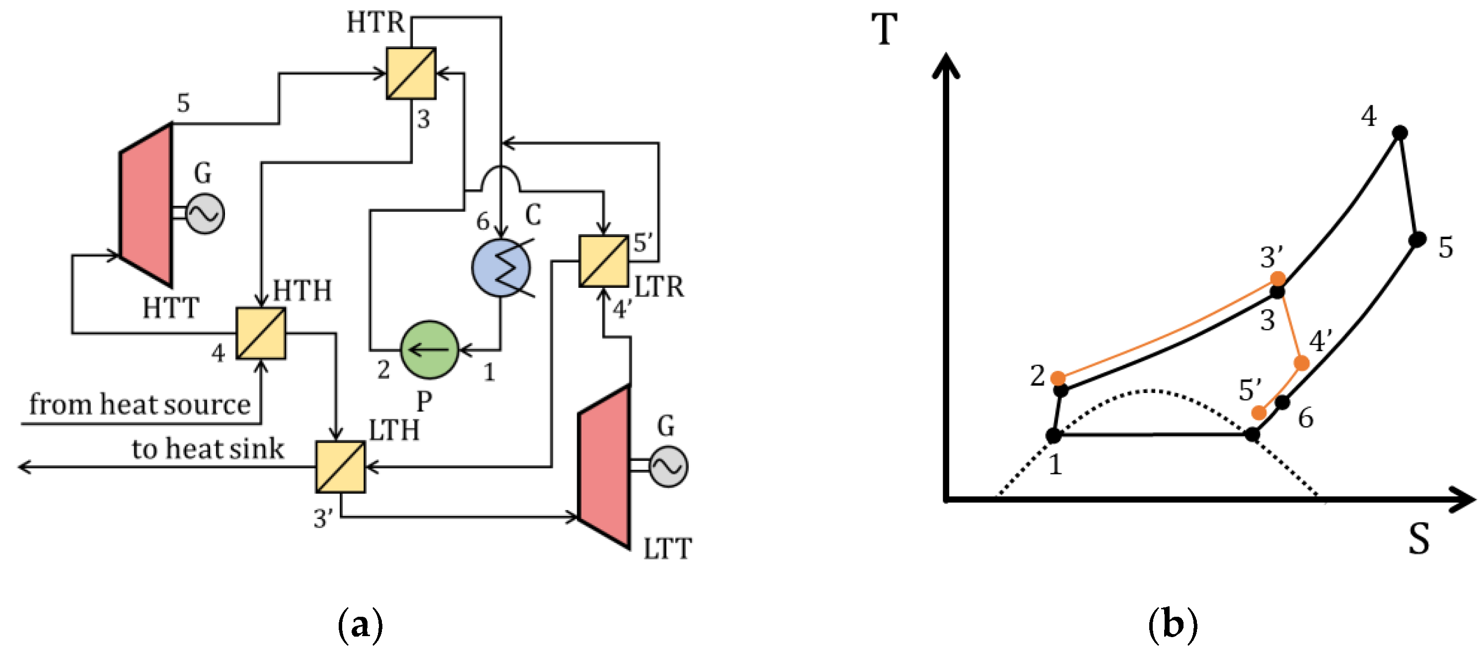
A schematic diagram of a power plant operating with the implementation of the cascade Rankine cycle with regeneration is shown in Figure 10. In this cycle, the working fluid is divided into two streams after compression in the pump (1–2). The first stream forming the cycle inner loop is first heated in the low-temperature regenerator (2–3′), after which, it is heated in the low-temperature heater (3′–4′) and further expands in the turbine, performing work, and then it is cooled in the low-temperature regenerator (4′–5′) and condensed in the condenser (5′–1).
The second stream forming the outer loop of the cycle, after compression in the pump, is heated in the high-temperature regenerator (2–3), then in the high-temperature heater (3–4) and then is used in the turbine (4–5) and cooled in the high-temperature regenerator (5–6) and condensed in the condenser (6–10), where it is combined with the first stream.
This cycle is more efficient than the basic Rankine cycle with regeneration due to the introduction of a lower-temperature internal loop; according to the source, at the same inlet temperatures, the cascade cycle increases the efficiency by 3–4% compared to the basic Rankine cycle with regeneration. The scheme disadvantages include a larger number of heat exchangers and the necessity of two separate turbine units, which significantly increase the metal consumption of the equipment.
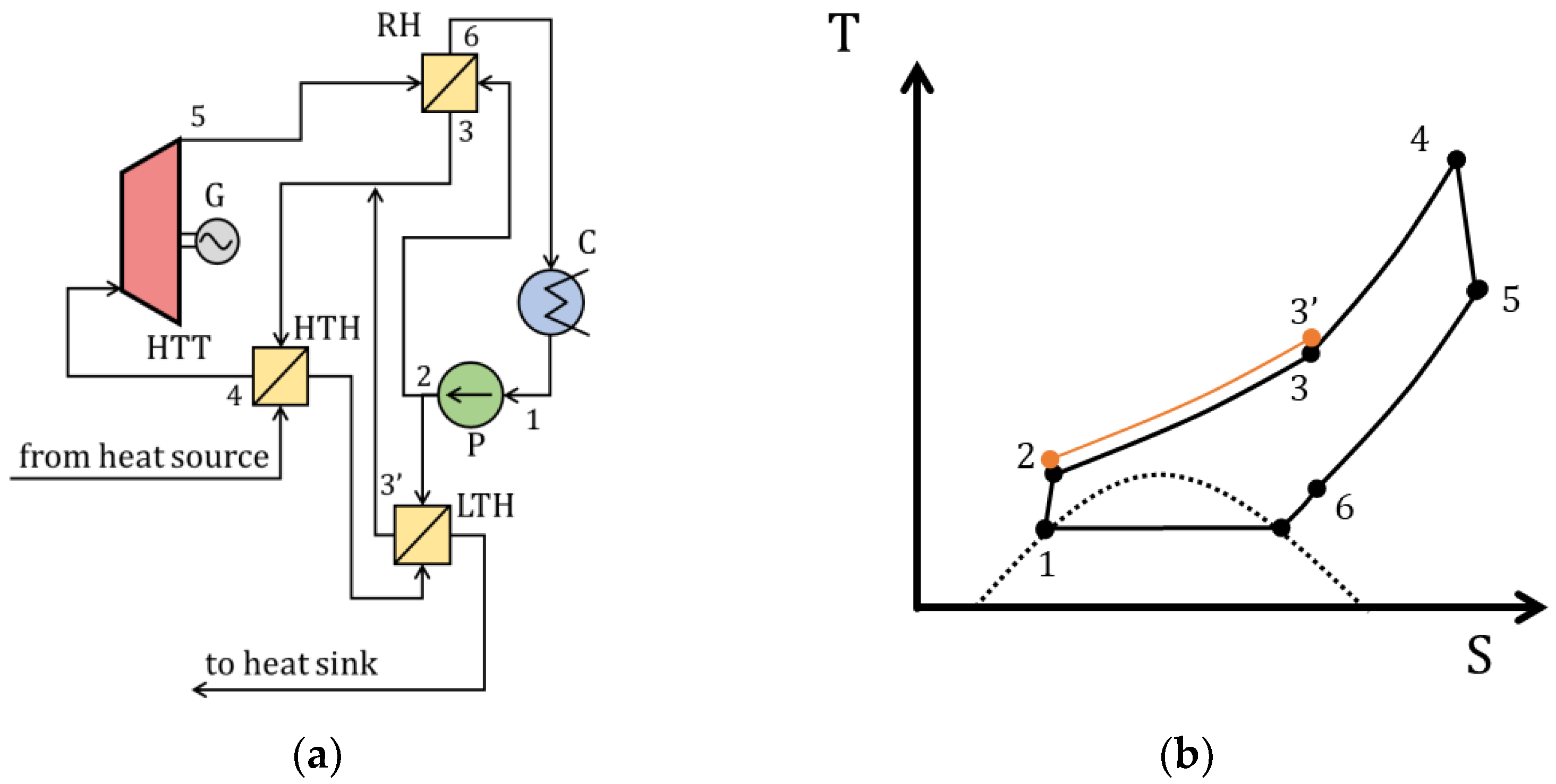
According to [14], the split Rankine cycle with regeneration and preheating is the best option as it has the highest efficiency and relatively low metal consumption due to the smaller heat exchange surface area and number of turbine units. The increased efficiency is due to the absence of a low-temperature turbine with low efficiency. The efficiency of this cycle is 6% greater than that of the basic cycle with regeneration at the same temperatures and 3% greater compared to a cascade cycle.
A schematic and T–S diagram of the split Rankine cycle with regeneration and preheating are shown in Figure 11. In this cycle, similar to the previous cycle considered, the working fluid after compression by the pump is divided into two streams. The first stream is heated in the regenerator (2–3), and the second stream is heated in the low-temperature heater (2–3′), after which, it is combined with the first one.

2.3. Prospective Closed Cycles

The prospective closed cycles utilizing supercritical carbon dioxide include modifications of the closed Brayton and Rankine cycles, which allow an increase in the cycle efficiency and expand the range of applicability. In this paper, the following modifications of closed supercritical CO2 power cycles are considered:
  • Supercritical carbon dioxide Brayton cycle with liquefied natural gas;
  • Supercritical carbon dioxide Brayton cycle with trigeneration;
  • Supercritical carbon dioxide Rankine cycle with ejection of the working fluid;
  • Supercritical carbon dioxide Brayton cycle with partial condensation of the working fluid.
Currently, liquefied natural gas (LNG) is one of the promising, environmentally friendly fuels with wide applicability and a high level of technological readiness. The attractiveness of liquefied natural gas is due to the possibility of its transportation by sea with subsequent regasification in regasification terminals. Liquefied natural gas has a low temperature (−163 °C), and its regasification occurs by heating; sea water is most often used as a heater. Thus, in most cases, the cold energy is discharged into the sea and is not used.
In [20,21], it was proposed to use liquefied natural gas to increase the energy efficiency of Brayton CO2 power cycles by reducing the cooling temperature of the working fluid. The schematic diagram of the Brayton cycle using liquefied natural gas and the T–S diagram are shown in Figure 12.
In this cycle, carbon dioxide is cooled in the regenerator (5–6) and in the cooling heat exchanger (6–1), where it heats the LNG. Thus, a coolant with a very low temperature is used as a cooling fluid, which significantly increases the cycle efficiency. The efficiency is 52% at a turbine input gas temperature of 550 °C. This scheme’s disadvantages include the ability to use it only near a regasification terminal, and, also, LNG’s disadvantage in general is its high cost—a kilogram of LNG is more than twice as expensive as pipeline natural gas.
Carbon dioxide belongs to low-boiling heat carriers; the boiling point at atmospheric pressure is −56 °C, so it can be used not only as a working fluid in the energy cycle, but also as a sufficiently efficient refrigerant in the refrigeration cycle. The use of high-boiling substances, for example, water, as refrigerants is impractical, since it requires a high degree of vacuum and powerful vacuum compressors to maintain low pressures. On the other hand, the energy cycle itself implies the possibility of waste heat regeneration to generate thermal energy. For Rankine cycles running on a water coolant, cogeneration plants, which generate electric power and thermal energy, have been known since the first half of the 20th century. Installations which simultaneously generate electric power, thermal energy and cold are called trigeneration installations.
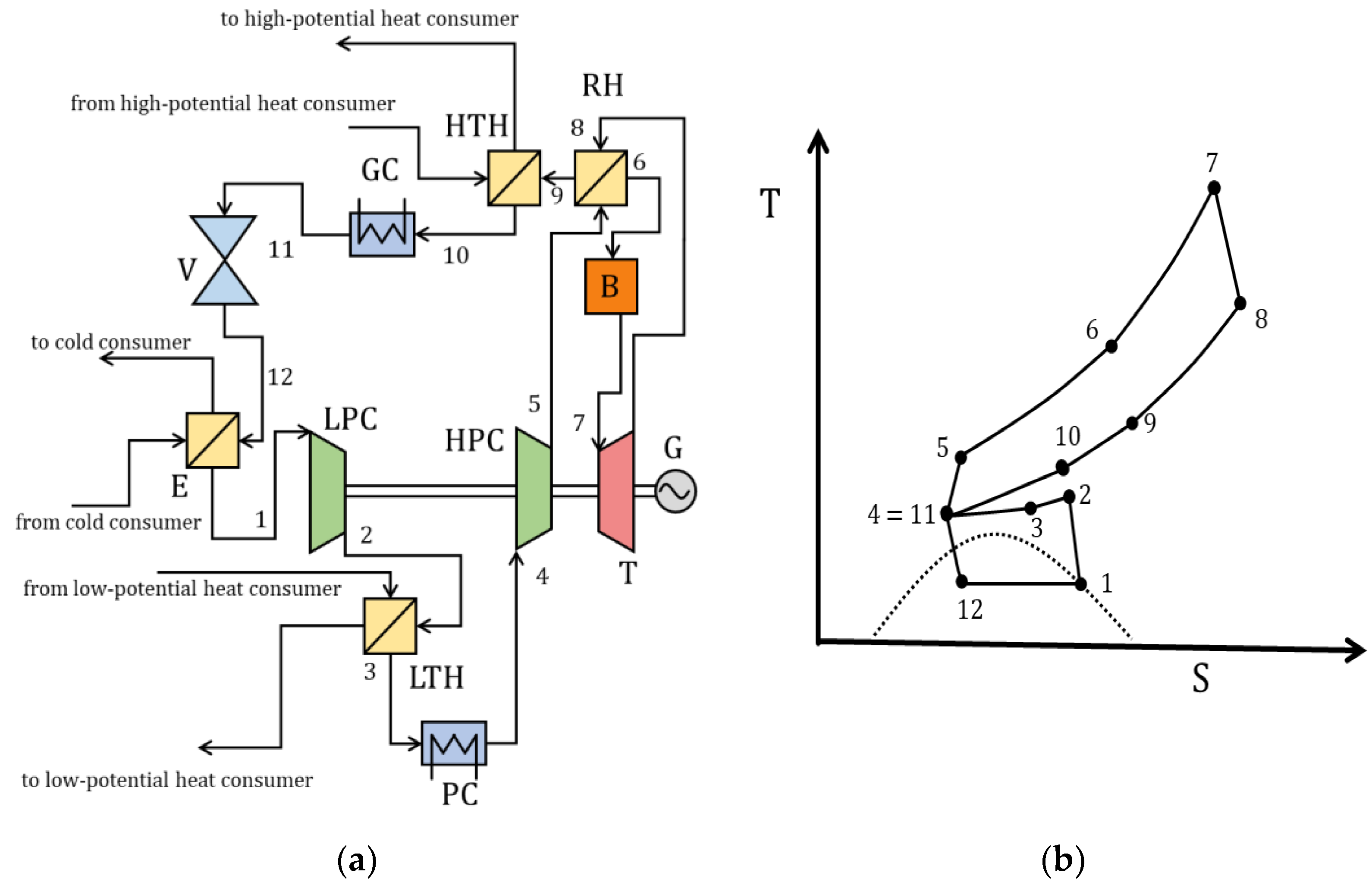
Figure 13 shows the schematic diagram and T–S diagram of the proposed Brayton cycle with trigeneration based on supercritical carbon dioxide. After compression in the high-pressure compressor (4–5), carbon dioxide is heated in the regenerative heat exchanger (5–6) and enters the heater (boiler) (6–7), after which, it expands in the turbine (7–8) connected to the electric generator. Next, the working fluid is cooled in the regenerative heat exchanger (8–9) and cooled in the electric heater while transferring thermal energy to a high-potential heat consumer (9–10) (80 °C); after that, it is cooled in the gas cooler (10–11). Next, the gas passes through the throttle (11–12) with a decrease in pressure and temperature, and then the cold, two-phase fluid takes heat from the cold consumer (5 °C) (12–1) and turns into a gaseous state, and it is compressed in a low-pressure compressor (1–2). After the low-pressure compressor, the gas is cooled and gives heat to the WHR consumer (45 °C) (2–3), after which, it enters the cooler and is cooled before the high-pressure compressor (3–11). The advantages of this scheme include its high efficiency, available provided that thermal energy, cold energy and electric power are considered equivalent. According to work [22], the total efficiency of such a plant is 78%. This scheme’s disadvantages include high complexity and the necessity of a large number of pieces of compressor equipment and heat exchangers, which negatively affect the plant cost.
One of the promising areas for using supercritical CO2 power cycles is WHR, especially low-potential WHR. Traditionally, the most effective CO2 power cycle is considered to be the Rankine cycle. However, for low-temperature cycles, the problem of a low-pressure drop between isobars at heating and cooling temperatures, which significantly reduces the mechanical work of turbines and plant power, is relevant. Ejectors are sometimes used to increase the pressure drop between the turbine input and output. Actually, the use of an ejector means that the flow is throttled; pressure decreases both due to the flow acceleration in the narrow part of the ejector and due to additional hydraulic losses. The disadvantages of using ejectors are the decrease in the plant efficiency and the increase in metal consumption due to the introduction of additional elements.
In [23], the Rankine cycle based on supercritical carbon dioxide with an ejector was considered. The plant schematic diagram and T–S cycle diagram are shown in Figure 14. In this cycle, condensed carbon dioxide is divided into two streams, one of which is heated in a low-temperature heater (2–7) and expands in the tapering part of the ejector (7–6) while maintaining pressure difference between the turbine input and output. The second stream is heated in the high-temperature heater (3–4), after which, it expands in the turbine (4–5) and is fed into the expanding part of the ejector, thus, increasing the pressure (5–6). After the ejector, both streams are combined and condensed in the condenser (6–1). The cycle efficiency is 7% at a heat source temperature of 100 °C.
Using a pump for compression is more efficient than using a compressor. In [24], a Brayton cycle with working fluid condensation using acetone to dissolve carbon dioxide was considered. A schematic diagram and T–S cycle diagram are shown in Figure 15. After compression in the compressor (5′–6), carbon dioxide is cooled and dissolved in acetone (6–1). After that, the mixture is compressed by the pump (1–2). According to [19], the cycle efficiency at the turbine inlet temperature of 1400 °C is 56%.

3. Semi-Closed Oxy–Fuel Combustion Power Cycles with CO2 Recirculation

Unlike closed CO2 cycles, where the working fluid heating is carried out from outside by means of a heat exchanger (boiler, heat recovery boiler, etc.), in semi-closed cycles, the working fluid heating occurs in the combustion chamber, where the fuel burns in a carbon dioxide environment with an oxidizer supplied. After that, additional carbon dioxide formed during fuel combustion is separated from the main stream; after expansion in the turbine, it is compressed and utilized. This approach allows two problems to be solved:
  • Optimization of the structure of the metal consumption of the main equipment due to the absence of massive boiler units;
  • Minimization of greenhouse gas emissions into the atmosphere through carbon dioxide capture and deposition.
Closed thermodynamic cycles with oxygen–fuel combustion are energy complexes consisting of the cycle itself, oxygen production plants and plants for carbon dioxide preparation for deposition. The following closed thermodynamic cycles have become widely known: a semi-closed cycle with oxygen–fuel combustion (SCOC-CC), MATIANT cycles, NET Power cycles (Allam cycle), Graz cycles, “water” (CES) cycles and membrane cycles (AZEP cycle, ZEITMOP) [25]. The first modifications of these cycles appeared at the end of the last century. Today, the USA, Japan and European countries are actively developing these technologies. By grant making, the active financing of “green” electric power generation technologies, creating legislative bases to stimulate the reduction of carbon dioxide emissions and conducting scientific research, experimental installations are being built, and prerequisites are being created for the development of power units with “zero” emissions of harmful substances. Large energy corporations are joining forces to create demonstration plants capable of releasing up to 50 MW of electric power to the grid [10].
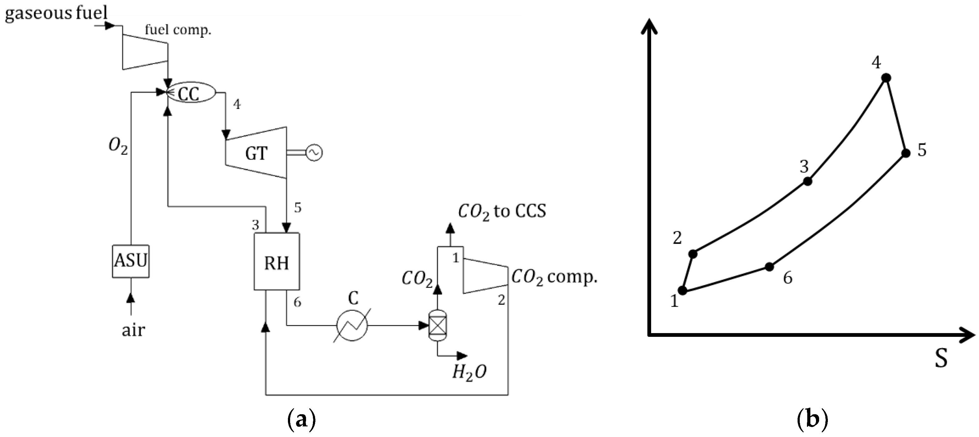
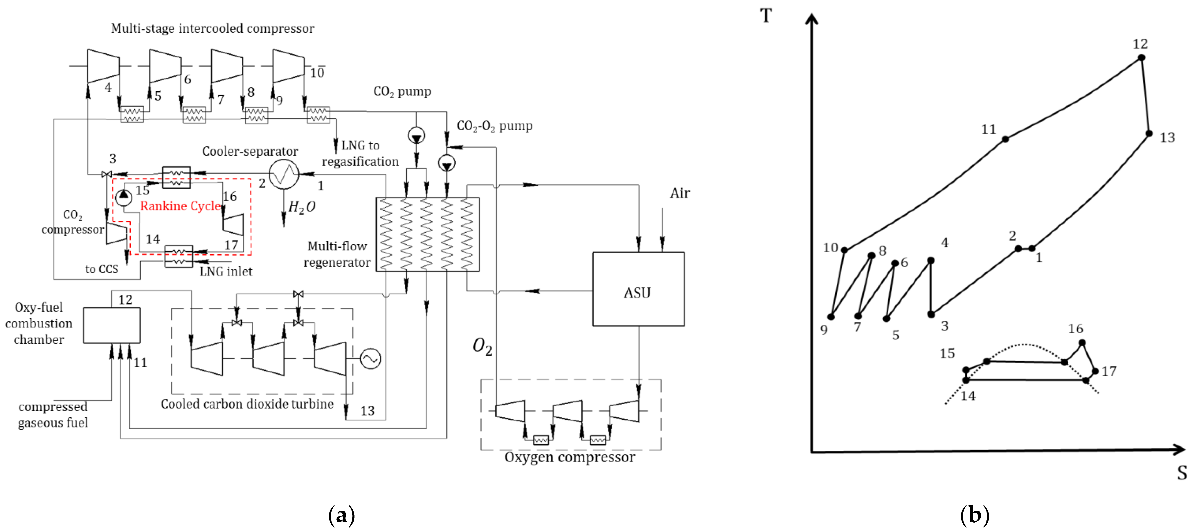
According to the technology of oxygen–fuel combustion, three streams enter the combustion chamber of the oxy–fuel energy complex: fuel (gaseous, including gas produced from coal), oxygen and a stream of carbon dioxide, limiting the maximum temperature in the combustion chamber. A mixture of carbon dioxide and water vapor is formed as a result of the burning reaction (3–4). Predominantly, a two-component fluid at a temperature from 1000 to 1700 °C is directed to the cooled turbine, the fluid expands in the turbine (4–5) and then enters a surface heat exchanger, which can be a heat recovery boiler or a regenerative heat exchanger (5–6). Having given away most of the heat energy, the flow is directed to the cooler–separator (CS). In the CS (6–1), the working fluid cooling is accompanied by the formation of a condensate of water vapor removed from the cycle. After that, the flow rich in carbon dioxide is sent to the compressor (1–2), increases its pressure and then is fed for recirculation into the combustion chamber. Thus, the thermodynamic cycle is closed [26]. To replenish the material balance, part of the working medium is removed for deposition. Carbon dioxide storage tanks can be both natural and artificial. A schematic diagram and T–S diagram of the oxygen–fuel energy complex are shown in Figure 16.
The above cycles can be classified according to their methods for obtaining oxygen and limiting combustion chamber temperature. The oxygen–fuel cycle using cryogenic air separation units (ASU) includes a semi-closed cycle with oxygen–fuel combustion, such as the Allam cycle and the Graz cycles. The AZEP and ZEITMOP cycles use high-temperature membrane ASUs integrated into the thermal circuit. Temperature limitation in the combustion chambers of oxygen–fuel cycles is achieved by recirculating part of the working fluid flow. In this, chemical composition of the recirculation flow may vary. So, in a semi-closed cycle with oxygen–fuel combustion (the MATIANT cycle and the Allam cycle), a stream of carbon dioxide, which, in these cases, is the main component of the working fluid, is supplied for recirculation, and, in the Graz cycles and the “water” cycle, a stream with a high content of water vapor is provided.
A common feature of these cycles is the almost complete absence of harmful gas emission into the atmosphere. Oxygen–fuel technology allows the sequestering of up to 99% of the CO2 generated as a result of burning carbon fuel in oxygen. The remaining technical and economic parameters of prospective TPP cycles, according to available estimates, differ significantly.
Within the framework of this work, the following semi-closed cycles with oxygen–fuel combustion are considered in detail:
  • Semi-closed cycle with oxygen–fuel combustion (SCOC-CC);
  • MATIANT and E-MATIANT cycles;
  • The Allam cycle.

3.1. SCOC-CC

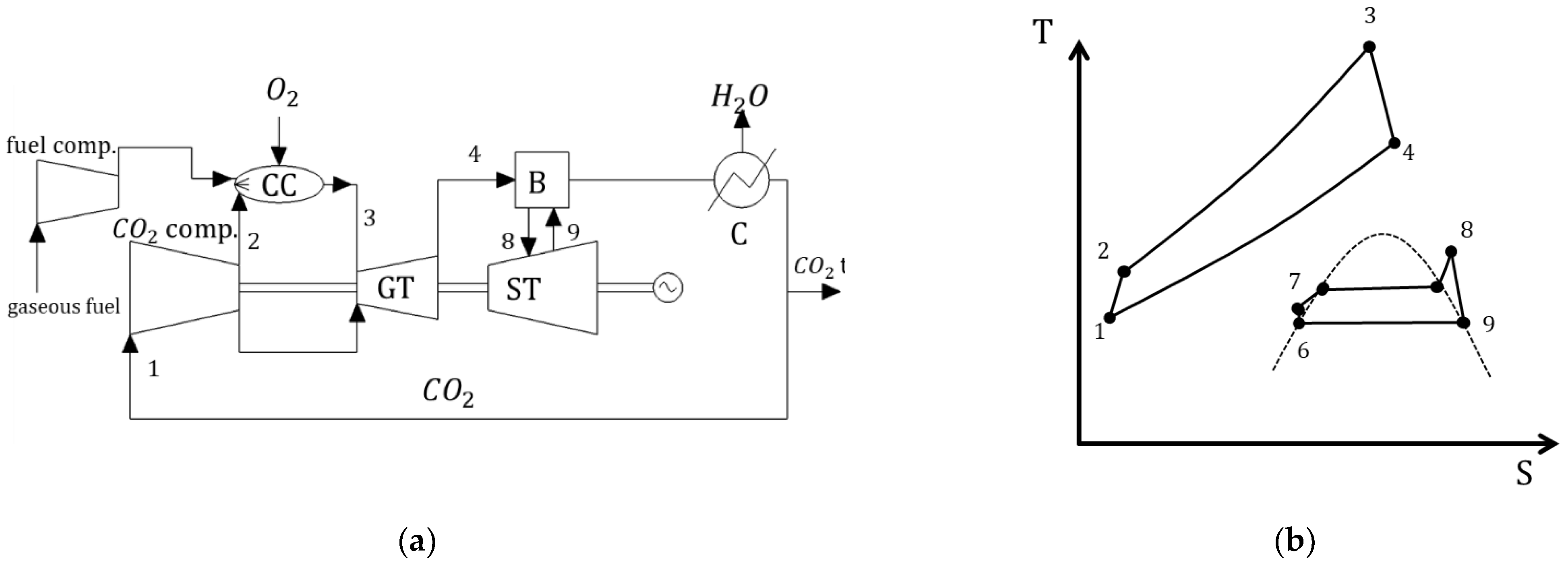
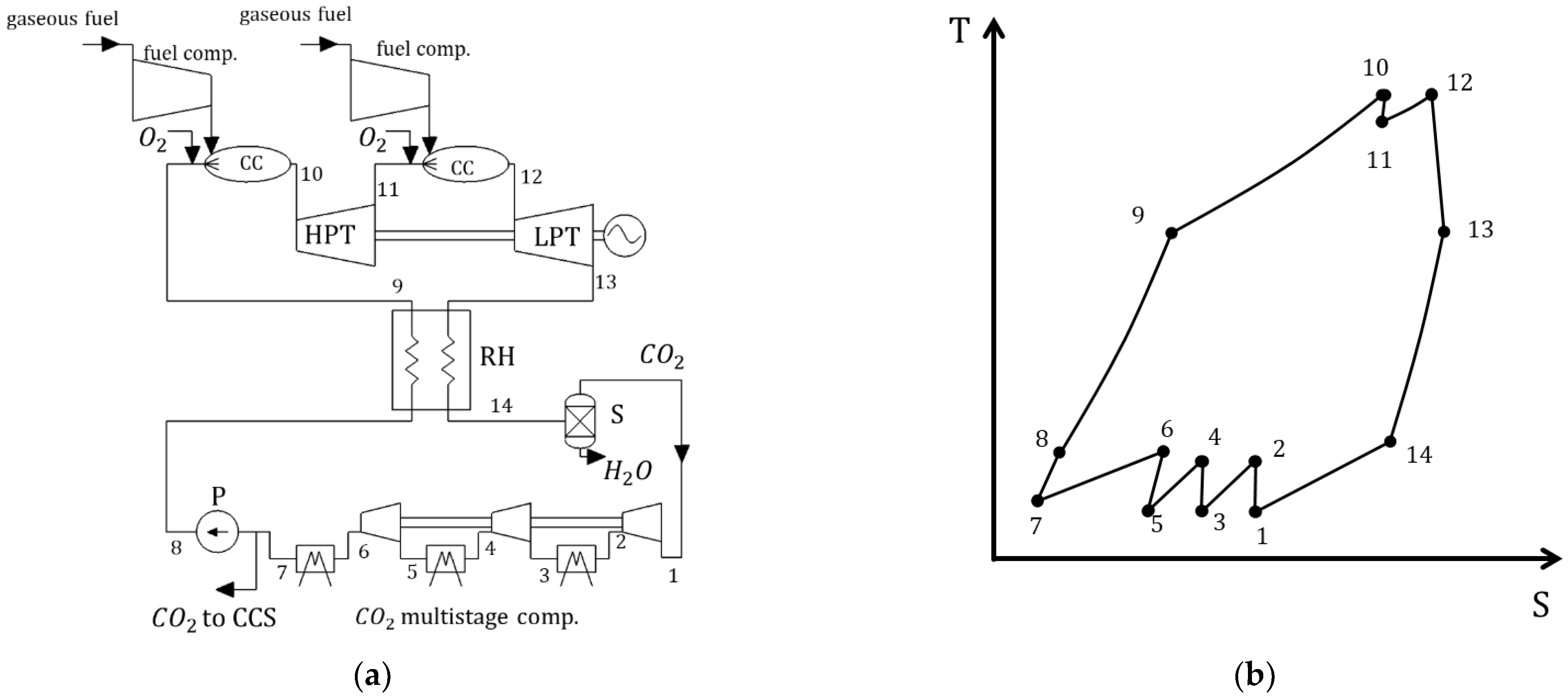
The semi-closed cycle with oxygen–fuel combustion, which was proposed for the first time in 1992 by scientists Bolland and Saether [27], has a simple configuration and is essentially a combined Brayton–Rankine cycle with an oxygen–fuel oxidizer and dioxide recirculation. The main advantage of the CO-CC cycle among closed cycles with oxygen–fuel combustion is the ease of implementation. A schematic diagram and T–S diagram of the SCOC-CC cycle are shown in Figure 17.
The gaseous fuel and high-purity oxygen are supplied into the combustion chamber with a stoichiometric ratio (2–3). Since the torch temperature during the combustion of such a mixture can reach 3500 °C, a third stream is also fed into the combustion chamber—a mixture with a high CO2 content, which is necessary to limit maximum temperature. The resulting gas flow, consisting of approximately 80% CO2 at a temperature of 1300–1400 °C, is directed to a gas turbine (3–4), which causes rotation of the electric generator. After expansion in the GT, the working fluid enters the heat recovery boiler (4–1). Due to regeneration of the combustion product heat at the GT output, superheated steam is generated in the combustion chamber and feeds the steam turbine (ST), which is also used to generate electric power (6–7–8–9). Flue gases at the combustion chamber output are directed to the condenser, in which the separation of most water due to its condensation at a pressure close to atmospheric pressure takes place. Then, part of the carbon dioxide flow is removed from the cycle for subsequent sequestration. The rest of the flow, consisting mainly of carbon dioxide, is recirculated and enters the compressor input.
Unlike open gas turbine cycles, in which the main component of the working fluid is nitrogen, in a semi-closed cycle with oxygen–fuel combustion, the proportion of carbon dioxide in the working fluid composition varies from 80 to 96%. In this cycle, the chemical composition of the working fluid depends on many factors, including type of fuel used, oxidizer purity, the thermodynamic parameters of the recirculation flow and the amount of excess air required to achieve complete combustion.
Since the cycle is semi-closed, the minimum pressure does not necessarily have to be equal to atmospheric pressure. On the one hand, an increase in the minimum pressure leads to a decrease in the turbomachinery and combustion chamber dimensions; on the other hand, it increases the wall thicknesses of the power equipment. Studies of the effect of minimum pressure on the efficiency of a semi-closed cycle with oxygen–fuel combustion have shown that its increase from 1 to 10 bar leads to a change in efficiency of only 0.5% [28]. However, at increasing pressure, an important problem is the cooling of the gas turbine blades. On the one hand, increased operating pressure reduces volumetric flow rate and, consequently, surface area to be cooled. On the other hand, the heat transfer coefficients on both sides of the cooled channels increase, and, consequently, the total heat flow through the blade walls becomes greater. This, in turn, leads to an increase in the temperature difference along the blade thickness with reduction of the permissible increase in the cooler temperature in the internal cooling channels. As a result, more refrigerant is consumed to remove the same heat flow. These factors confirm the expediency of maintaining the exhaust pressure of the SCOC-CC cycle gas turbine at the atmospheric level.
Results of analysis of the recirculation flow temperature effect on energy efficiency and design features of a semi-closed cycle with oxygen–fuel combustion are given in [29]. On the one hand, a decrease in the temperature of the recirculation flow leads to a decrease in the amount of compressor work and, on the other hand, an increase in cold source losses, primarily due to the increase in the proportion of condensed moisture. In this paper, it was shown that there is no clear optimum for this parameter; for gas temperature at the GT output equal to 620 °C, it is in the range from 40 to 70 °C. Accordingly, to achieve maximum cycle efficiency, the recirculation flow temperature should be slightly higher than the temperature of the cold source.
The working medium initial parameters at the gas turbine input have the greatest impact on energy efficiency of the SCOC-CC cycle. According to the research results given in [30], the net efficiency of the semi-closed cycle with oxygen–fuel combustion at gas inlet temperatures equal to 1300–1400 °C and degrees of pressure increase in the range of 30–45 varies in the range of 45–48%.
The optimal degrees of pressure increase for the initial temperatures of the working fluid at 1400 and 1600 °C are approximately equal to 60 and 90 bar, respectively, which is significantly more than for traditional gas turbine plants [31].

3.2. MATIANT Cycles

The concept of the MATIANT cycle was presented for the first time in 1997 by two inventors, Mathieu and Jantowski [32]. A distinctive feature of this technology is the expansion of a working mixture with a high content of carbon dioxide in three turbines: high-, middle- and low-pressure turbines (HPT, LPT1, LPT2) (Figure 18).
Carbon dioxide is compressed in the multi-stage compressor (1–2–3–4) with intermediate cooling to a pressure of 300 bar and enters the regenerator for heating (4–5). After taking part of the heat from the gases at the LPT (5–6) output, the heated flow is directed to the HPT, where it expands to a pressure of 40 bar and returns to the regenerator (6–7) for reheating. From the regenerator output, the flow is directed to the first cooled combustion chamber (7–9), where the temperature rises to 1300 °C due to the combustion reaction of the fuel supplied to the chamber in the oxygen contained in the working mixture. Then, the hot combustion products expand in the cooled LPT1 (8–9), after which, they are sent to the second cooled combustion chamber, to which fuel and oxygen are also supplied. From the combustion chamber output (9–10), the heated working fluid is sent to the cooled LPT2, where it expands to approximately atmospheric pressure (10–11). A hot carbon dioxide stream at the LPT2 output serves as the hot fluid of the regenerator. From the regenerator output, the flow is directed to a condenser, in which, in addition to cooling the working fluid due to heat transfer to the environment, water condensation also occurs with subsequent separation.
The results of the thermodynamic studies given in [33] revealed a significant influence of the compressor internal relative efficiency on the MATIANT cycle efficiency; with an increase in internal relative efficiency from 75 to 90%, the energy complex net efficiency is increased by 5.5%. A decrease in maximum pressure (pressure at the HPT input) from 300 to 150 bar leads to a decrease in net efficiency of about 1%, and an increase in the MPT input pressure from 40 to 100 bar increases net efficiency by more than 3%.
The above estimates were obtained without a detailed calculation of the process of working fluid expansion in cooled LPT1 and LPT2. The decrease in net cycle efficiency due to turbine cooling losses was assumed to be 2.5%. However, taking into account the overheating of the working fluid at the LPT1 and LPT2 input, total consumption for cooling has a noticeable effect on the cycle efficiency at the high initial parameters, which causes a significant error in the authors’ estimation of the technology efficiency. More accurate thermodynamic studies require the development of a methodology for determining consumption for cooling and losses at carbon dioxide turbine cooling or adaptation of existing methods for traditional gas turbines operating with air as a working fluid and refrigerant.
In addition to developing an efficient turbine cooling system, when designing the MATIANT cycle, special attention should be paid to the regenerative heat exchanger. Creating this element may require large capital costs due to the significant heating surface area and high cost of materials (nickel alloys) necessary for its manufacture. Cold carbon dioxide flow at the compressor output with a pressure of 300 bar should be heated to 600–700 °C by the heat taken from the LPT output working fluid with a temperature and pressure at the regenerator input of 900–1000 °C and 1 bar. Currently, heat exchangers with such high temperatures and pressure differences are not used in the energy industry.
A modification of the technology under consideration called the “E-MATIANT” cycle was proposed in [34]. Advantages of this new cycle version consist of the reduction in the number of thermal circuit elements, reduction in the maximum cycle pressure and greater efficiency due to reducing the losses for compression in the compressor (Figure 19). The working fluid expansion takes place in two cooled turbines of high (10–11) and low (12–13) pressure. At the input of each turbine, its own cooled combustion chamber is installed, and fuel and oxygen are supplied into the chambers in addition to the working fluid. From the second turbine output, the working fluid is fed to the regenerator while heating the compressed carbon dioxide at the pump output.
The minimum pressure in the “E-MATIANT” cycle, similar to that in the prototype, is close to atmospheric pressure, and the input HPT pressure has an optimum: 60 bar. Optimization is carried out for a constant working fluid temperature at turbine inputs equal to 1300 °C and underheating in the regenerator equal to 20 °C. The isentropic efficiency of the compressor used in the calculations is in the range between 85% (three first stages) and 80% (last stage). Maximum efficiency of the “E-MATIANT” cycle achieved at an input pressure of 60 bar is 47%, excluding turbine cooling losses.

3.3. Allam Cycle

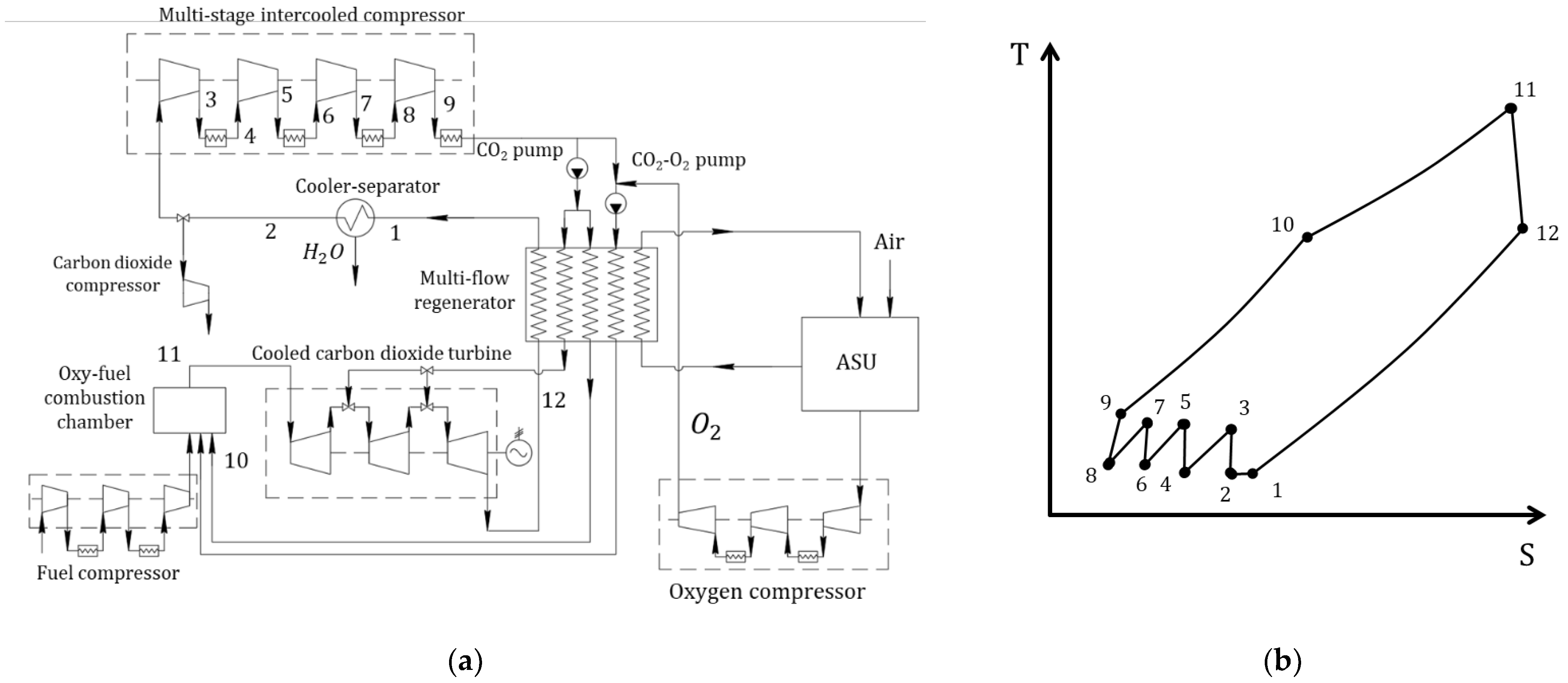
The concept of the Allam cycle was patented in 2010 by inventor Rodney John Allam [35]. A simplified schematic thermal diagram of the Allam cycle using natural gas is shown in Figure 20. The technology allows the achievement of a net efficiency of 48% with CO2 emissions close to zero. In comparison, the net efficiency of natural gas combined cycle (NGCC) power units using sequestration technology does not exceed 48%, and that of steam-gas plants with coal gasification and sequestration is 39% [36].
In the Allam cycle, carbon dioxide is compressed in a multi-stage compressor with intermediate cooling up to 80 bar (2–8) and then it is fed to the pump (8–9), after which, it reaches maximum pressure in the cycle in the range from 200 to 400 bar. After the pump, the carbon dioxide is sent to the regenerator (9–10), where it is heated to 700–750 °C by the heat of the working fluid at the turbine output and the heated refrigerant used for the intermediate cooling of the oxygen in the plant for carbon dioxide preparation. Processing in the regenerator of WHR produced at intermediate oxygen cooling makes it possible to compensate the thermal balance between the hot and cold flows. After the regenerator, most of the carbon dioxide flow is directed into the combustion chamber (10–11); in order to limit maximum temperature, a smaller part is used to cool the gas turbine. The remaining carbon dioxide is mixed with the compressed oxygen stream and is also sent to the combustion chamber. In the combustion chamber, the working fluid temperature increases to 1150 °C due to the combustion of fuel with oxygen. The use of carbon dioxide recirculation in order to limit temperature at the GT input causes the working fluid to consist of 90% carbon dioxide. Expansion in the GT wheel space (11–12) occurs to a pressure of 20–30 bar, which is less than the critical pressure of carbon dioxide. From the GT output, the working fluid is sent to the regenerator (12–1). The optimal pressure of the working fluid at the gas turbine input is in the range from 200 to 400 bar, and the degree of pressure reduction in the turbine is in the range from 6 to 12 [37].
An important advantage of this technology is the competitive unit cost of installed capacity. The specified indicator for the Allam cycle using natural gas is equal to 1400–1500 $/kW due to the compactness of the entire plant and power equipment caused by the high minimum pressure of the working fluid in the range of 20–40 bar and the absence of traditional steam-gas cycle elements (steam turbine, recovery boiler, steam pipelines, devices for reducing emissions of nitrogen oxide, carbon monoxide, sulfur, synthesis gas cooler, catalysts, etc.).
The creation of a gas turbine and combustion chamber using the Allam cycle is possible on the base of existing groundwork for the development of steam turbine and gas turbine technologies. The Allam cycle temperatures are lower than the temperatures in modern gas turbine and steam-gas cycles but significantly higher than temperatures in steam turbine cycles. In other words, the maximum pressure does not exceed the pressure in the latest steam turbines but exceeds the pressure in gas turbines at times.
The absence of the danger of nitrogen oxide formation makes it possible to concentrate efforts in the design of the Allam cycle combustion chamber to achieve high indicators of structural durability and efficiency of the burning process. Moreover, the main indicator of combustion chamber efficiency is the content of carbon monoxide in the combustion products, which can be minimized by optimizing the combustion chamber length.
An important difference between the Allam cycle combustion chamber and the combustion chamber for traditional GT is the presence of at least three supply streams: fuel (natural gas), oxidizer (oxygen) and maximum temperature limiter (carbon dioxide). The hot stream at such a combustion chamber’s output consists mostly of carbon dioxide.
Advantages of the Allam cycle in comparison with other oxygen–fuel cycles are its high efficiency, compactness and, as a result, the relatively low cost of a kilowatt of installed capacity. The disadvantages include, first of all, the fact that the maximum temperature at the turbine input is limited by the maximum permissible temperature and the pressure of the working fluid in the regenerator, which, in turn, depends on the alloys used for their manufacture.

3.4. Modified Semi-Closed Oxy–Fuel Combustion Power Cycles with CO2 Recirculation

For cycles with oxygen–fuel combustion, the working fluid temperature at the turbine input is limited only by the heat resistance of the combustion chamber materials but can be increased using cooled turbine blades; therefore, improving the gas turbine blade cooling efficiency is one of the areas of research required to improve the energy efficiency of the cycles under consideration. The second direction of research towards improving the oxygen–fuel energy cycles’ efficiency relates to WHR sources, as well as decreasing the cooling temperature of the working fluid, that is, in general, this direction can be described as decreasing the “temperature of the cold source”.
A separate direction for improving semi-closed CO2 power cycle efficiency is creating energy technology complexes based on oxygen–fuel power plants, which generate electric power and produce hydrogen by electrolysis from water or in conversion reactors from natural gas. It is planned that the produced hydrogen or synthesis gas can serve as fuel for energy generation and storage and also as fuel for transport.
In the framework of this paper, the following promising modifications of oxygen–fuel cycles using supercritical carbon dioxide are considered:
  • SCOC-CC cycle with refrigerant cooling;
  • SCOC-CC cycle with water injection;
  • SCOC-CC cycle with WHR;
  • Allam cycle using liquefied natural gas for cooling;
  • Allam cycle with WHR;
  • MATIANT cycle with production of electric power and methane in Sabatier reactors.
Paper [38] considered the cooling of turbine blades using the cooled condensate of the second circuit in the SCOC-CC cycle, as well as the cooling of turbine blades using water injection. Figure 21 shows a schematic diagram and T–S diagram of the SCOC cycle with cooling turbine blade refrigerant.
The difference between this cycle and the basic SCOC-CC cycle consists of the use of an additional heat exchanger for the cooled turbine blade refrigerant. In this heat exchanger, the refrigerant is cooled by the condensed water of the second circuit, and the water, in turn, is heated by the heat removed (line 8–9 in Figure 21b). Furthermore, reducing the refrigerant temperature allows the reduction of the flow, which increases the efficiency of the turbine. The use of this approach allows an increase in the cycle efficiency of 3.2%. The scheme disadvantages include the necessity of an additional heat exchanger, which increases the power unit metal consumption and, as a result, capital cost.
The second method considered in [34] to reduce the cooled blade refrigerant consumption of carbon dioxide turbines was water injection. Figure 22 shows a schematic diagram of a power plant implementing the SCOC-CC cycle with water injection. Water injection reduces the temperature of the refrigerant due to evaporation. Water for injection can be taken from the cooler–separator, which eliminates the need for additional expensive water treatment. Water injection makes it possible to increase the cycle efficiency by 1.5% compared to the basic version, which is less than in the case of cooling by a second circuit condensate. Advantages of this scheme include the simplicity and cheapness of the water injection implementation, which does not have a big impact on the power unit specific capital costs.
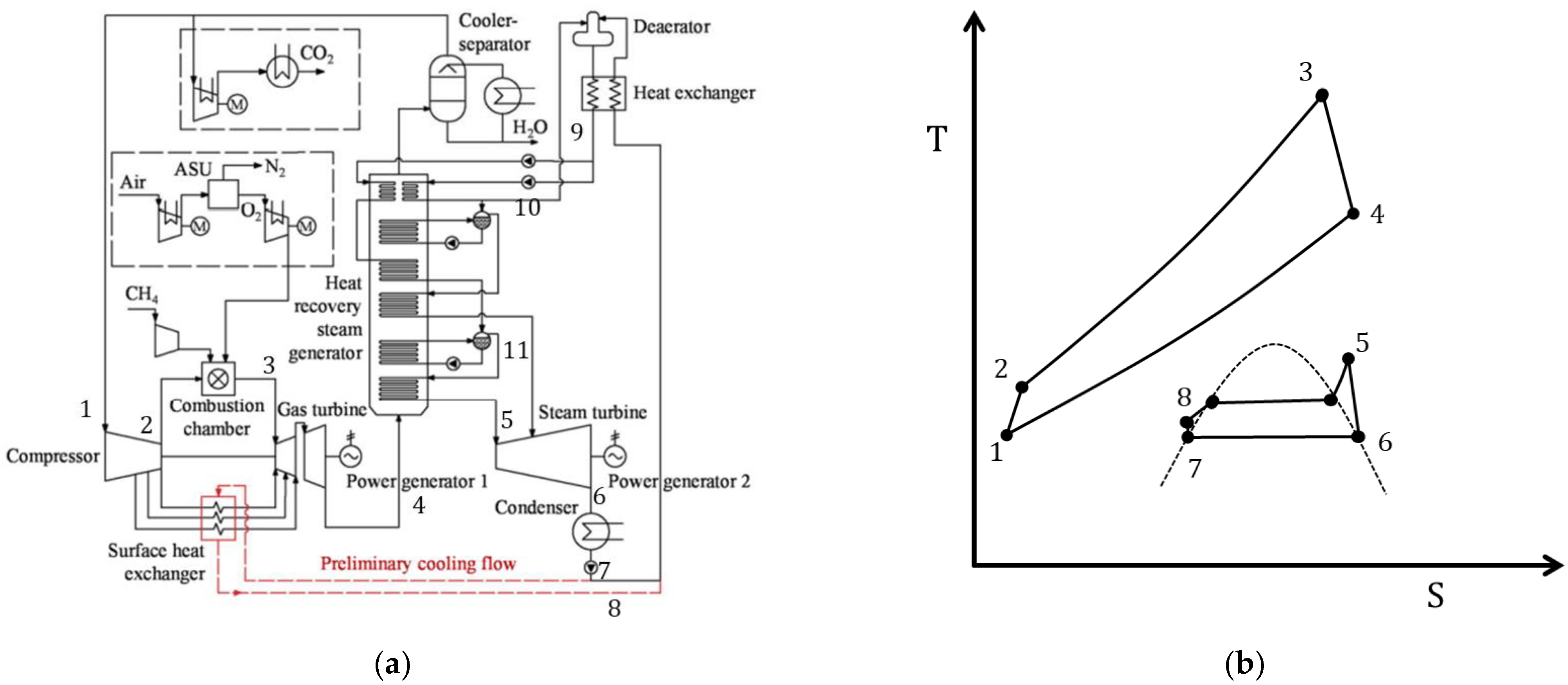
Patent [39] proposed a modified SCOC-CC cycle with WHR sources by introducing an additional low-temperature Rankine cycle based on supercritical carbon dioxide. As a result, this trinary cycle includes a Brayton cycle based on supercritical carbon dioxide, the Rankine cycle based on water vapor and the Rankine cycle based on supercritical carbon dioxide. Figure 23 shows the cycle schematic diagram and its T–S diagram. As can be seen from Figure 23, the main difference between the considered cycle and the basic SCOC-CC cycle is the presence of a Rankine cycle based on supercritical CO2 (curve 9–13 in the T–S diagram). According to [35], the introduction of an additional cycle makes it possible to increase the plant efficiency by 6% compared to the basic cycle options at similar temperatures of supercritical CO2 at the gas turbine input. The disadvantage of the cycle, similar to that of other schemes with WHR, is the significant increase in capital costs.
For the Allam cycle, the issue of WHR is also relevant. The Allam cycle provides for a large number of compressors which require cooling of the working fluid for more efficient compression. In particular, cooling is required for compressors used to compress the oxygen at the output of the ASU.
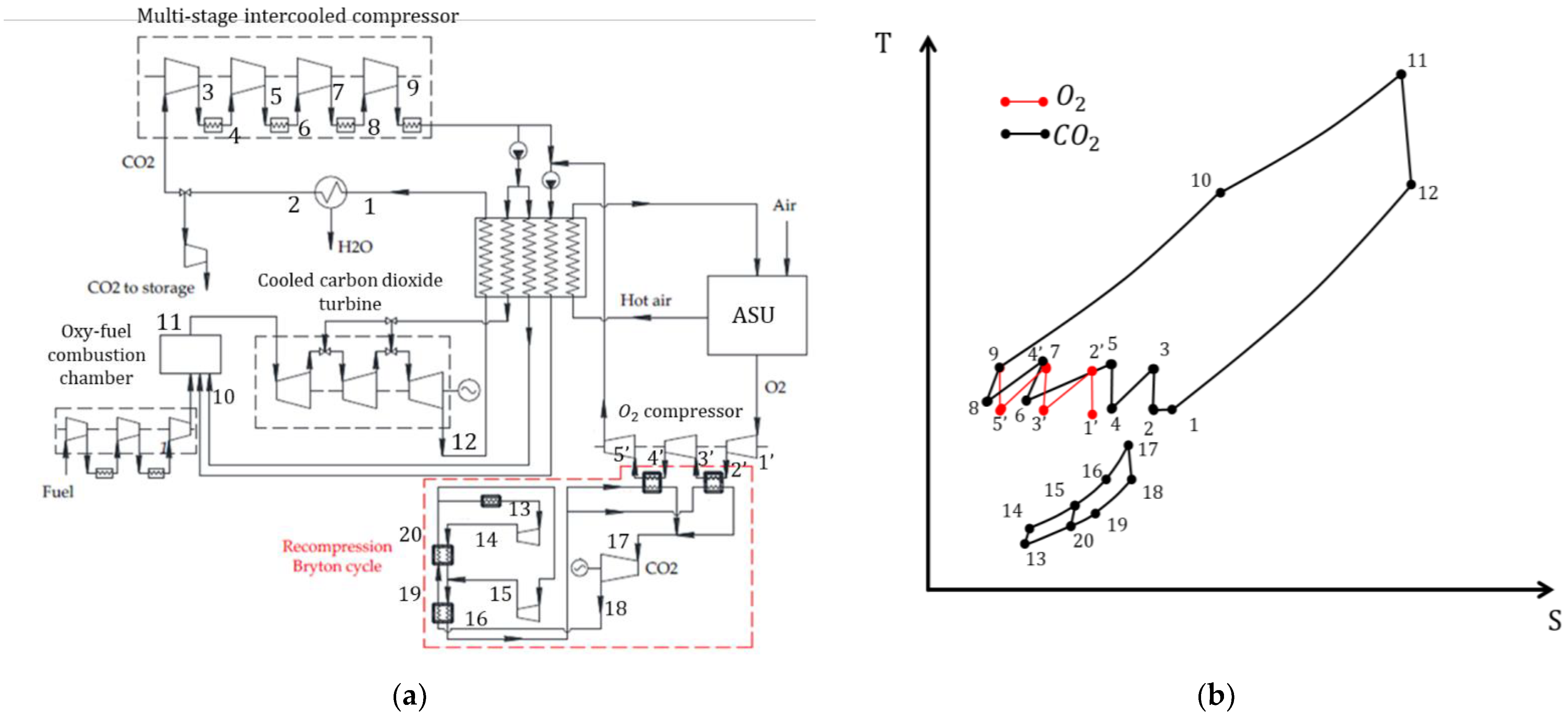
Paper [40] proposed a modification of the Allam cycle with WHR when cooling compressors at the output of the ASU using the Brayton cycle with recompression. A schematic diagram and T–S diagram of this cycle are shown in Figure 24. In this cycle, in the process of multi-stage compression after leaving the ASU, oxygen is sequentially cooled after each compressor stage (line 1′–5′) while transferring heat to the Brayton cycle with recompression, after which, it is compressed in the last stage of the oxygen compressor and combined with the flow of compressed carbon dioxide. Further, the Allam cycle remains unchanged. This solution makes it possible to increase the cycle efficiency by 3.7% compared to the basic version of the Allam cycle with the same gas parameters at the turbine input (1083 °C and 30 MPa). The disadvantage of the cycle, similar to other schemes with WHR, is the significant increase in capital costs.
Efficient compression in a multi-stage CO2 compressor also requires cooling after each stage. In [41], it was proposed to use liquefied natural gas for cooling. In addition, the paper also proposed the WHR of cooled carbon dioxide after a separator–cooler, using liquefied natural gas as a cold source. Despite the low temperature of carbon dioxide before the compressor, the use of liquefied natural gas with a temperature of −163 °C allows for a sufficient temperature difference for the energy cycle functioning. A schematic diagram of the proposed equipment and T–S cycle diagram are shown in Figure 25.
In the considered cycle, when carbon dioxide is cooled after water separation (line 2–3 on the T–S diagram), the working fluid is heated in the heat exchanger according to the organic Rankine cycle scheme and then is expanded in the turbine, cooled and condensed in the cooler and is compressed by the pump. At this point, the Rankine organic cycle cooler uses liquefied natural gas coming from a cooling natural gas storage facility. Further, the LNG successively enters heat exchangers designed to cool carbon dioxide after its compression in the compressor stages (line 3–10 on the T–S diagram). Advantages of the considered cycle include the highest efficiency of the Allam cycles, considered equal to 53%, and the scheme disadvantages include high capital costs for the equipment for the Rankine organic cycle, as well as a limited scope of application; the cycle can be implemented only in the immediate vicinity of the liquefied natural gas regasification terminal.
One of the ways to increase economic indicators and energy generation efficiency is currently the production of hydrogen or other fuels, for example, synthesis gas or synthetic methane, as an additional product or during periods of low energy demand for energy for storage in the form of chemical fuel energy. The production of combustible gases at oxygen–fuel power units has a high attractiveness since carbon dioxide emissions into the atmosphere are minimal at these power units, which ensures the carbon neutrality of the product produced. A promising direction is the production of synthetic methane from carbon dioxide and hydrogen, which makes it possible to utilize carbon dioxide more efficiently from an economic point of view.
In [42], the MATIANT cycle using a part of carbon dioxide as a component for the production of synthetic methane was investigated. In this cycle, part of the carbon dioxide formed during burning is sent for deposition (34%), and most of it is mixed with hydrogen obtained by electrolysis from water, compressed in a compressor and then sent to a Sabatier reactor. During the Sabatier reaction, methane and water, as well as by-products hydrogen, carbon monoxide and carbon dioxide, are formed in the presence of a nickel catalyst. A cycle schematic diagram is shown in Figure 26.
The advantage of the described schematic diagram is the ability to deposit a lower volume of carbon dioxide, which reduces the requirements for CO2 storage, while the system has a sufficiently high efficiency of 43% at a gas turbine inlet temperature of 1300 °C. The cycle disadvantages include the high energy costs for electrolysis and the high cost of additional equipment, i.e., the electrolyzer and Sabatier reactor. Since the cycle under consideration includes not only energy generation, but also production of an additional product, it cannot be compared with other cycles in terms of technical and economic parameters.

4. Efficiency and Environment

When determining an energy development strategy, it is important to classify promising technical solutions by application, efficiency and environmental safety using numerical technical and economic characteristics as metrics of competitiveness. For power plants, these are:
  • Efficiency is a metric of energy conversion efficiency;
  • Specific capital costs—technology cost metric;
  • Power is a metric of the technology applicability for generating electric power at different scales;
  • Temperature at the turbine input is a metric reflecting potential sources of thermal energy;
  • Specific carbon dioxide emission per unit of energy produced—a metric of the environmental safety of the cycle;
  • Cost of generated energy in current and future conditions is a key metric reflecting total economic efficiency for an electric power producer.
The thermodynamic cycles considered in this paper are presented in Table 2 with the main efficiency metrics discussed above. Specific capital costs were calculated according to the methodology set out in [43,44]. For all cycles for which estimates of specific capital costs can be found within literature, values and ratios of capital costs for different cycles were taken into account. Specific carbon dioxide emission was calculated based on stoichiometric combustion reactions, taking into account efficiency, and natural gas was taken as fuel for all the cycles under consideration. For oxygen–fuel cycles, carbon dioxide capture efficiency was assumed to be 99%.
Specific capital cost was calculated for different power levels depending on the maximum reference power level described within literature:
  • For high-power cycles with a reference power of over 20 MW, the power for calculating specific capital costs was 300 MW;
  • For cycles with a low reference power from 0.2 MW to 20 MW, the power for calculating specific capital costs was 10 MW;
  • For cycles with a reference power less than 0.2 MW, the power for calculating specific capital costs was assumed to be equal to 0.1 MW.
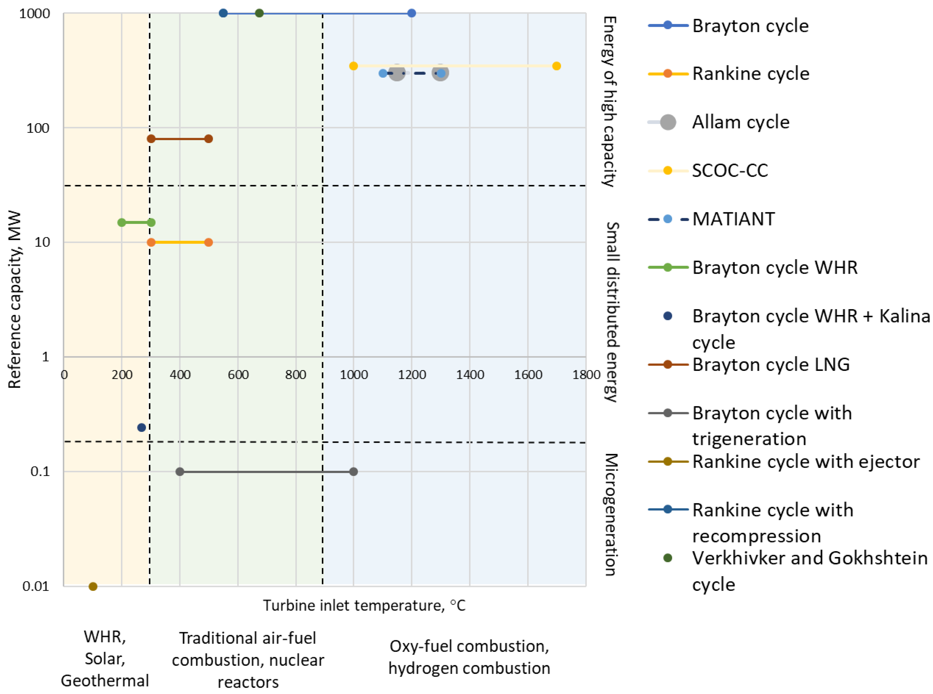
Taking into account the different reference powers of the considered cycles, as well as the turbine inlet temperatures, it is necessary to classify the cycles depending on their characteristics by application and generation scale. In Figure 27, a diagram showing the power levels and temperature at the turbine input for the considered cycles is given. The diagram presented in Figure 27 allows the division of CO2 power cycles into categories by power level and heat source depending on reference temperatures.
The implementation of projects using CO2 power cycles is advisable only in the case of availability of high-capacity energy technologies comparable to the current level; therefore, in order to determine the most promising CO2 power cycle technologies for high-capacity energy, it is necessary to compare reference points reflecting the current level of industrial electric power generation efficiency. The following technologies were considered as reference points for comparison with the current level of high-capacity energy technologies:
  • NGCC plants;
  • NGCC plants with carbon dioxide capturing;
  • NGCC plants with a gas turbine and a Brayton CO2 power cycle.
The characteristics used to determine the reference points are presented in Table 3.
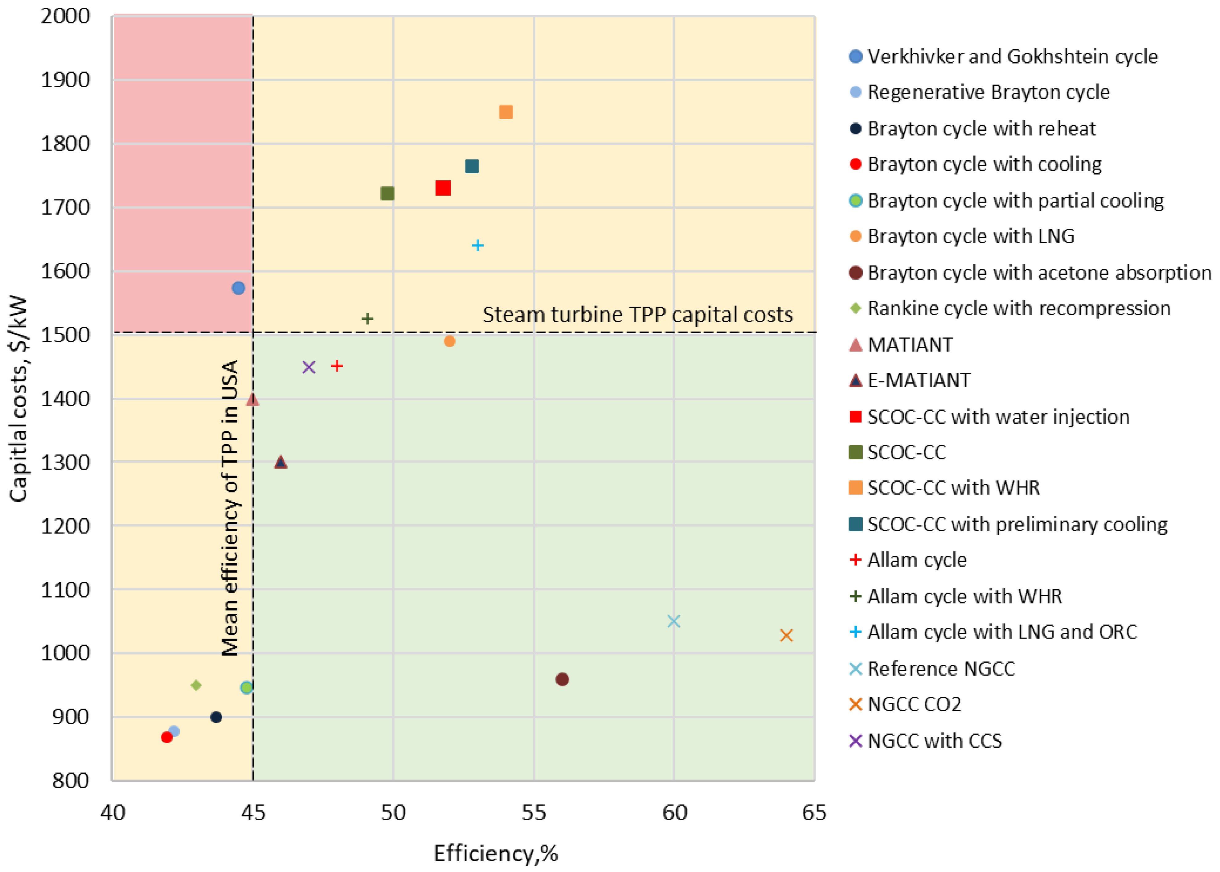
Figure 28 shows a diagram of the dependence between the efficiency and specific capital costs of CO2 power cycles and modern NGCC plants. The following values were established as critical values determining the technology competitiveness:
  • Efficiency of at least 45%, which is the average level of steam turbine plant efficiency in the USA;
  • Specific capital construction costs of not more than 1500 $/kW, reflecting the average capital intensity of traditional steam turbine power units.
As can be seen from the data given in Figure 28, the following high-power CO2 cycles fully meet the stated requirements for efficiency and capital intensity:
  • MATIANT;
  • E-MATIANT;
  • Brayton cycle using LNG;
  • Brayton cycle with acetone absorption;
  • Basic Allam cycle.
The only cycle which does not correspond to any cutting criteria is the Verkhivker and Gokhshtein cycle. All other cycles meet at least one of the requirements.
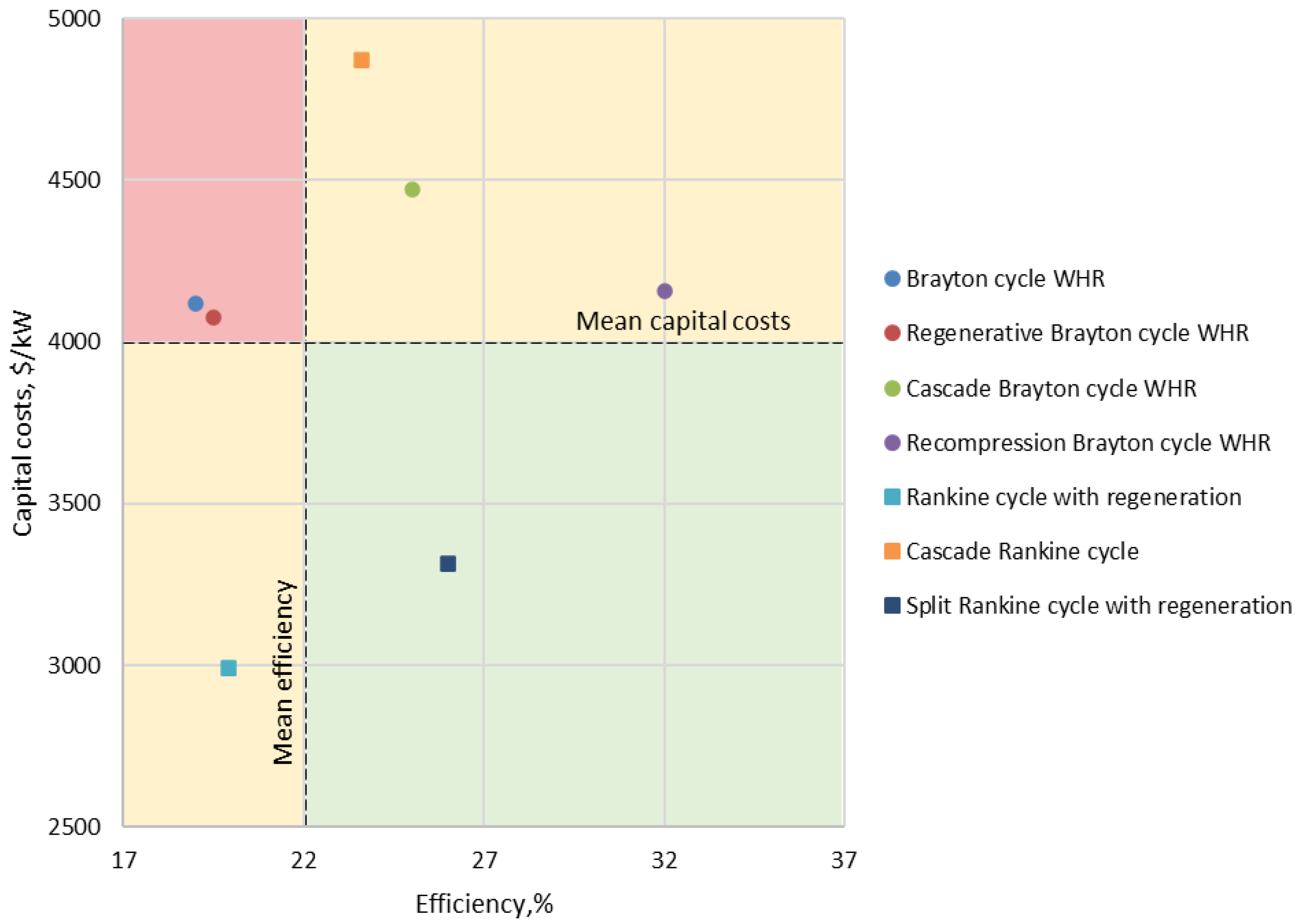
For CO2 power cycles, considered as solutions for small and distributed generation due to the absence of explicit reference points, the most effective cycles were determined based on comparison of the cycles among themselves (Figure 29). Average cycle characteristics were taken as indicative performance requirements:
  • Efficiency not less than 22%;
  • Specific capital costs not more than 4000 $/kW.
As can be seen from Figure 29, the only cycle which meets all the requirements is the split Rankine cycle with regeneration. The cycles that do not meet any of the efficiency criteria are the basic Brayton cycle WHR and the regenerative Brayton cycle WHR. All other cycles meet at least one of the criteria.
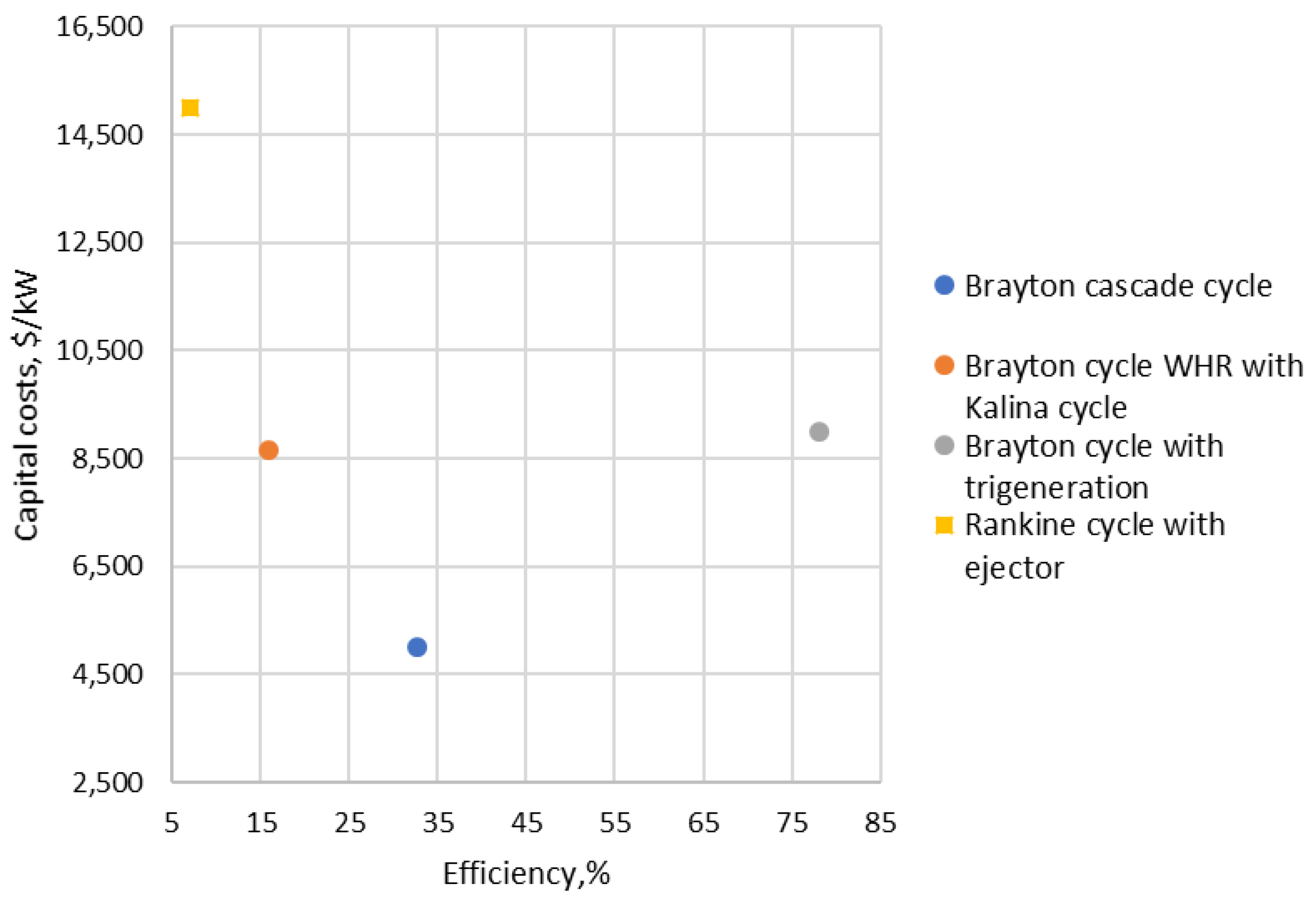
For CO2 power cycles selected as microgeneration technologies (Figure 30), due to low number of cycles, it does not seem feasible to determine the critical values for energy efficiency criteria. Nevertheless, two of the most efficient cycles in terms of efficiency and specific capital costs can be distinguished—the Brayton cycle with trigeneration and the cascade Brayton cycle.

5. Economics

Specific capital costs and efficiency are important indicators of the energy and economic efficiency of electric power generation technologies, but the key parameter in determining the most promising technologies is the cost of 1 kWh of electric power generation. The electric power cost includes both capital costs and operating costs, the main part of which is expenditure for fuel purchasing. Currently, in addition to the fuel costs, the cost of purchasing CO2 emission quotas is also becoming an important and significant component of the cost price.
CO2 emission quoting is a market mechanism for rationing greenhouse gas emissions into the atmosphere using market mechanisms for trading dioxide emission quotas similar to financial credit documents. Currently, the average cost of a quota for emissions of 1 ton of carbon dioxide is USD 50, while, by 2030, market prices for quotas are expected to rise to USD 100 per ton of CO2 equivalent.
It is expected that the increase in the market value of CO2 emission quotas will lead to an increase in selling prices for electric power and thermal energy for all producers; however, in such conditions, generating companies with the lowest cost of generating energy due to the lowest greenhouse gas emissions will receive the greatest net profit. Thus, the increase in the market value of CO2 emission quotas in the future should become a mechanism to stimulate the transition of generating companies to technologies, which ensures minimal greenhouse gas emissions into the atmosphere.
To determine the effect of increasing carbon dioxide emissions quota prices, it is necessary to estimate the cost of electric power at different market values of quotas and constant other input data. The electric power cost for the main expenditure categories was calculated by the ratio in Equation (1):
N c = 100 η · q f C f + E s · C e 10 6 + ( 1 + k a ) ( C c T o + S n · S h ) ,
  • N c —net costs of energy, $/kWh;
  • η —cycle efficiency, %;
  • q f —specific heat of combustion, kWh/kg;
  • C f —fuel costs, $/kg;
  • E s —specific CO2 emissions, g/kWh;
  • C e —cost of CO2 allowances, $/ton;
  • k a —additional costs coefficient;
  • C c —specific capital costs, $/kW;
  • T o —term of operating, hour;
  • S n —specific staffing, people/kW;
  • S h —staff hourly rate, $/hour.
The initial data for the calculation are given in Table 4.
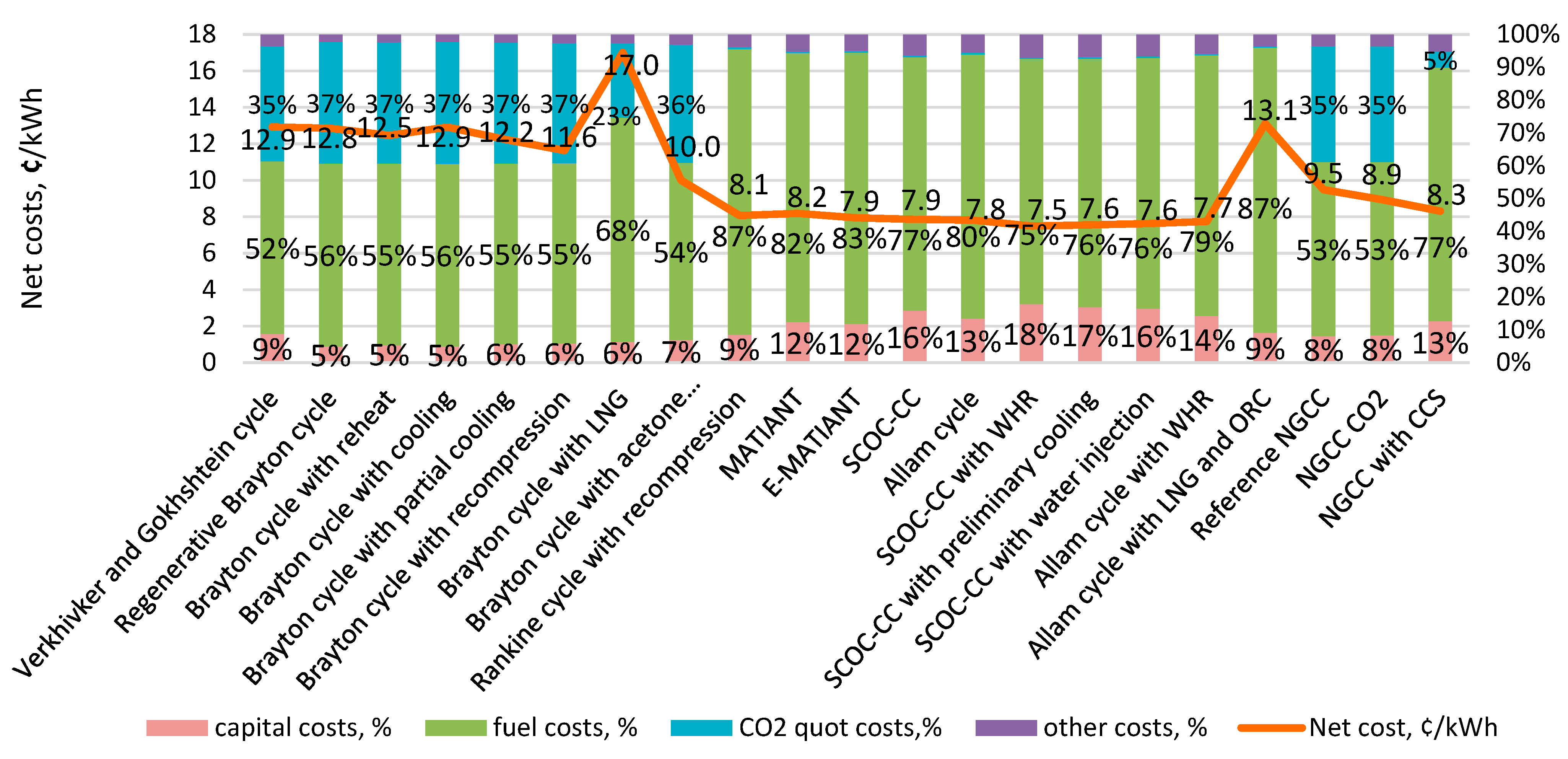
Figure 31 shows a diagram of the cost of electric power for high-capacity carbon dioxide and traditional high-power energy cycles at a carbon dioxide emission quota price of 50 $/ton. At this level of quota cost, the most attractive cycle from an economic point of view is a NGCC with a gas turbine and a CO2 power cycle due to its high efficiency and low capital costs. It is important to note that, even at this level of quota costs, traditional vapor-gas cycles and vapor-gas cycles with carbon dioxide capturing lose out in cost to Allam cycles and modified SCOC-CC cycles.
Figure 32 shows a diagram of the cost of various high-capacity CO2 power cycles in comparison with traditional cycles at a quota cost of 100 $/ton. As can be seen from Figure 32, under these conditions, quotas for CO2 emissions begin to make up a share of the cost of electric power comparable to fuel costs for cycles without carbon dioxide capturing, while the most attractive from an economic point of view is the SCOC cycle with WHR.
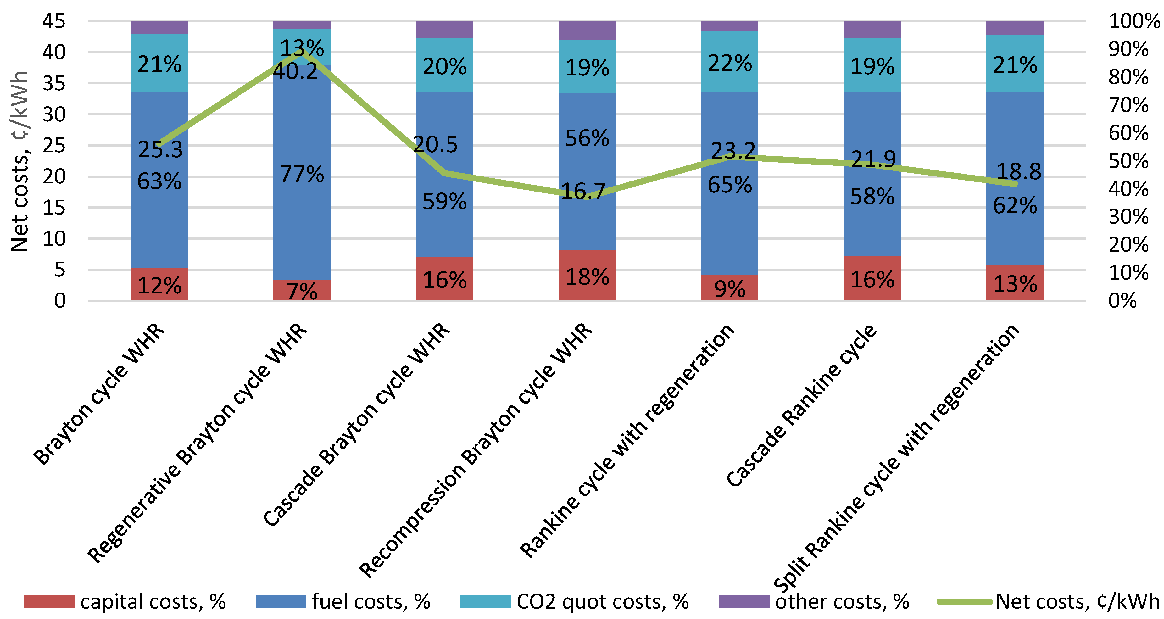
Figure 33 and Figure 34 show diagrams reflecting the value and structure of the electric power cost for low-power CO2 cycles. Since all low-power CO2 cycles have low efficiency and, accordingly, high specific greenhouse gas emissions, the overall cost picture does not change with changes in the quota cost; the Brayton cycle with recompression remains the most promising.
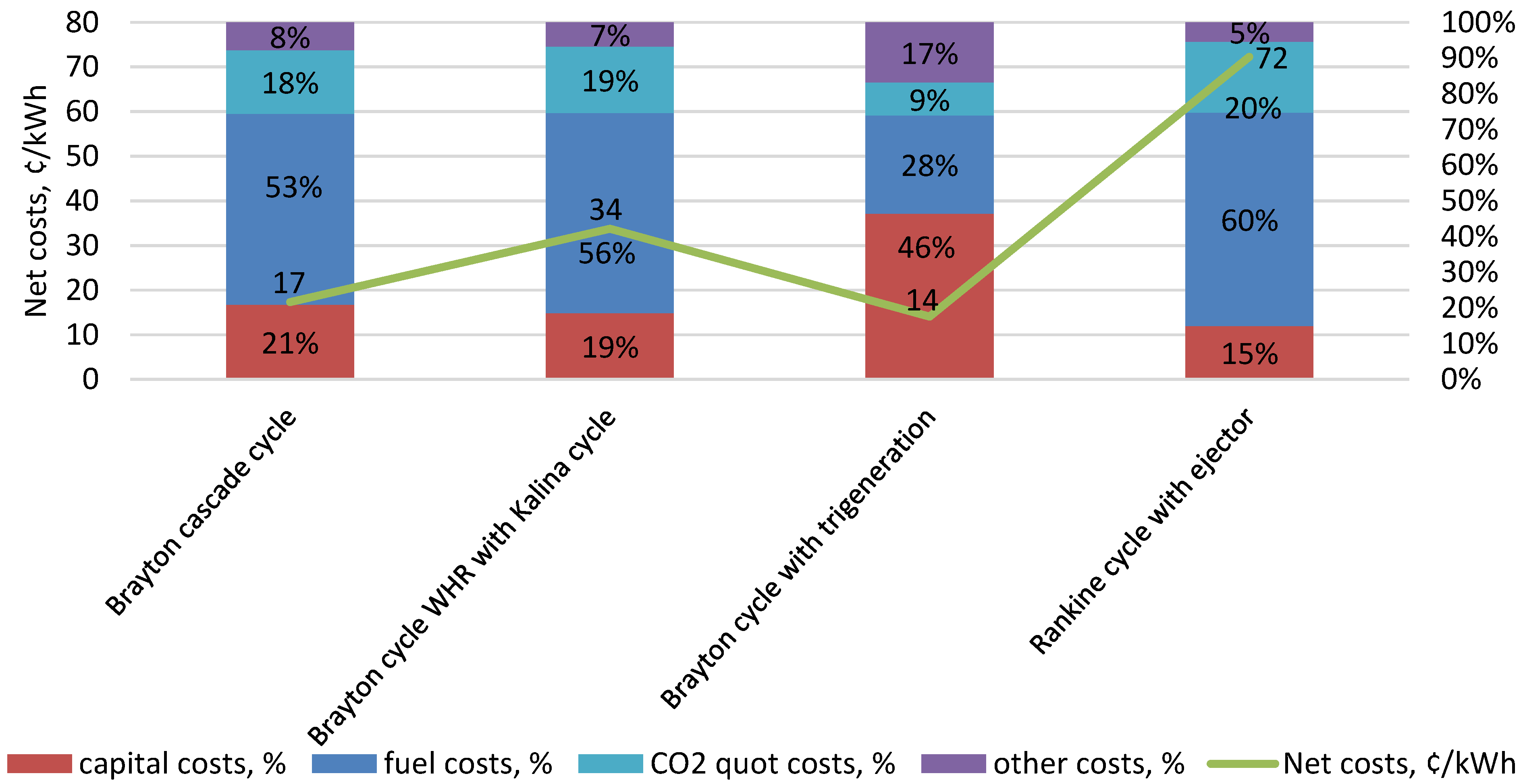
Figure 35 and Figure 36 show diagrams of the structure of the cost of electric power produced using CO2 power cycles for microgeneration. As can be seen from Figure 35 and Figure 36, the most promising cycle is the Brayton cycle with trigeneration. This cycle has a high attractiveness for microgeneration because of its high efficiency due to the generation of electric power, thermal energy and cold. The combined generation of thermal, electrical and cold energy also allows it to achieve energy savings for heating and cooling.

6. Summary

In the framework of this paper, closed and semi-closed energy cycles based on supercritical carbon dioxide were considered and analyzed. Based on efficiency and reference power levels, the studied cycles were divided by power level into high-capacity energy sources (over 20 MW), low-power, distributed power plants (0.2–20 MW) and microgeneration plants (less than 0.2 MW). According to the inlet temperature levels, the cycles were divided into the following categories depending on the potential sources of thermal energy:
  • Less than 300 °C: WHR sources, including solar energy collectors and geothermal sources;
  • 300–900 °C: traditional burning of solid, liquid and gaseous fuels in boilers, as well as nuclear reactors;
  • More than 900 °C: burning of gaseous fuel, including hydrogen, in pure oxygen.
The analysis of technical and economic features of CO2 power cycles demonstrated the following:
  • For large-capacity energy production, with an increase in the cost of CO2 emission quotas, oxygen–fuel cycles with carbon dioxide capturing become significantly more attractive from an economic point of view. In particular, at a quota cost of 50 $/ton, the NGCC with a gas turbine and supercritical Brayton cycle has the lowest cost of generating electric power, but, if the cost of quota is equal to 100 $/ton, the SCOC-CC cycle with WHR has the lowest cost of generating electric power;
  • Among the closed CO2 power cycles for large-capacity power generation, the Brayton cycle with acetone absorption is the most attractive in terms of the entire set of technical and economic parameters, and, among semi-closed oxygen–fuel cycles, the SCOC-CC cycles with high efficiency and relatively low specific capital costs are the most effective;
  • For CO2 power cycles used in small, distributed generation, the Brayton cycle with WHR and recompression is the most effective, which is achieved due to high efficiency and low specific capital costs;
  • For microgeneration cycles, the most effective among those considered is the Brayton cycle with trigeneration, which has the lowest cost of energy generation for all the considered values of CO2 emission quota.

Author Contributions

Conceptualization, N.R. and A.R.; methodology, V.K. and A.R.; software, V.K.; validation, V.K.; formal analysis, O.Z.; investigation, P.B.; resources, O.Z.; data curation, P.B.; writing—original draft preparation, P.B.; writing—review and editing, V.K.; visualization, O.Z.; supervision, A.R.; project administration, N.R.; funding acquisition, O.Z. All authors have read and agreed to the published version of the manuscript.

Funding

This study, conducted by the Moscow Power Engineering Institute, was financially supported by the Ministry of Science and Higher Education of the Russian Federation (project no. FSWF-2020-0020).

Institutional Review Board Statement

Not applicable.

Informed Consent Statement

Not applicable.

Data Availability Statement

Not applicable.

Conflicts of Interest

The authors declare no conflict of interest.

Nomenclature

SymbolDescriptionUnit
Nrefnet cycle powerMW
Tinletturbine inlet temperature°C
Trefreference turbine inlet temperature°C
ηcycle efficiency%
Ccspecific capital costs$/kW
Esspecific CO2 emissionsg/kWh
N c net costs of energy$/kWh
q f specific heat of combustionkWh/kg
C f fuel costs$/kg
C e cost of CO2 allowances$/ton
k a additional costs coefficient
T o term of operatinghour
S n specific staffingpeople/kW
S h staff hourly rate$/hour
Abbreviations
WHRWaste Heat Recovery
HFCHydrofluorocarbon
GWPGlobal Warming Potential
ORCOrganic Rankine Cycle
TPPThermal Power Plant
AGRAdvanced Gas-Cooled Reactor
SCO2Supercritical Carbon Dioxide
LNGLiquefied Natural Gas
SCOC-CCSemiclosed Oxy–Fuel Combustion Combined Cycle
SCOCSemiclosed Oxy–Fuel Combustion
CESClean-Energy Systems
AZEPAdvanced Zero-Emissions Plant
ZEITMOPZero-Emission Ion Transport Membrane Oxygen Power
GTGas Turbine
CCCombustion Chamber
STSteam Turbine
NGCCNatural Gas Combined Cycle

References

  1. Kotowicz, J.; Job, M.; Brzęczek, M. The characteristics of ultramodern combined cycle power plants. Energy 2015, 92, 197–211. [Google Scholar] [CrossRef]
  2. Pronobis, M. Reduction of nitrogen oxide emissions. In Environmentally Oriented Modernization of Power Boilers; Elsevier: Amsterdam, The Netherlands, 2020; pp. 79–133. ISBN 978-0-12-819921-3. [Google Scholar]
  3. Shi, L.; Shu, G.; Tian, H.; Deng, S. A Review of Modified Organic Rankine Cycles (ORCs) for Internal Combustion Engine Waste Heat Recovery (ICE-WHR). Renew. Sustain. Energy Rev. 2018, 92, 95–110. [Google Scholar] [CrossRef]
  4. Braimakis, K.; Karellas, S. Energetic optimization of regenerative Organic Rankine Cycle (ORC) configurations. Energy Convers. Manag. 2018, 159, 353–370. [Google Scholar] [CrossRef]
  5. Sun, W.; Yue, X.; Wang, Y. Exergy efficiency analysis of ORC (Organic Rankine Cycle) and ORC-based combined cycles driven by low-temperature waste heat. Energy Convers. Manag. 2017, 135, 63–73. [Google Scholar] [CrossRef]
  6. Siddiqui, M.E. Thermodynamic performance improvement of recompression Brayton cycle utilizing CO2-C7H8 binary mixture. Mechanics 2021, 27, 259–264. [Google Scholar] [CrossRef]
  7. Bianchi, M.; Branchini, L.; De Pascale, A.; Melino, F.; Ottaviano, S.; Peretto, A.; Torricelli, N. Performance modelling and greenhouse impact assessment of a micro-orc energy system working with HFCs, low GWP fluids and mixtures. E3S Web Conf. 2021, 238, 10002. [Google Scholar] [CrossRef]
  8. Bahrami, M.; Pourfayaz, F.; Kasaeian, A. Low Global Warming Potential (GWP) Working Fluids (WFs) for Organic Rankine Cycle (ORC) applications. Energy Rep. 2022, 8, 2976–2988. [Google Scholar] [CrossRef]
  9. Liu, C.; He, C.; Gao, H.; Xie, H.; Li, Y.; Wu, S.; Xu, J. The environmental impact of organic Rankine cycle for waste heat recovery through life-cycle assessment. Energy 2013, 56, 144–154. [Google Scholar] [CrossRef]
  10. Allam, R.; Martin, S.; Forrest, B.; Fetvedt, J.; Lu, X.; Freed, D.; Brown, G.W.; Sasaki, T.; Itoh, M.; Manning, J. Demonstration of the Allam cycle: An update on the development status of a high efficiency supercritical carbon dioxide power process employing full carbon capture. Energy Procedia 2017, 114, 5948–5966. [Google Scholar] [CrossRef]
  11. Gokhshtein, D.P.; Verkhivker, G.P. Use of carbon dioxide as a heat carrier and working substance in atomic power stations. Sov. Energy 1969, 18, 430–432. [Google Scholar] [CrossRef]
  12. Rogalev, N.; Rogalev, A.; Kindra, V.; Komarov, I.; Zlyvko, O. Structural and parametric optimization of S–CO2 nuclear power plants. Entropy 2021, 23, 1079. [Google Scholar] [CrossRef] [PubMed]
  13. Angelino, G. Carbon dioxide condensation cycles for power production. J. Eng. Gas Turbines Power 1968, 90, 287–295. [Google Scholar] [CrossRef]
  14. Huang, M.; Sonwane, C. Thermodynamics of conventional and non-conventional SCO2 recompression brayton cycles with direct and indirect heating. In Proceedings of the 4-th International Symposium-Supercritical CO2 Power Cycles, Pittsburgh, PA, USA, 9–10 September 2014. [Google Scholar]
  15. Angelino, G. Real gas effects in carbon dioxide cycles. In Proceedings of the International Gas Turbine Conference and Products Show, Cleveland, OH, USA, 10–13 March 1969. [Google Scholar]
  16. Bonalumi, D.; Giuffrida, A.; Sicali, F. A case study of cascade supercritical CO2 power cycle for waste heat recovery from a small gas turbine. Energy Convers. Manag. X 2022, 14, 100212. [Google Scholar] [CrossRef]
  17. Astolfi, M.; Alfani, D.; Lasala, S.; Macchi, E. Comparison between ORC and CO2 power systems for the exploitation of low-medium temperature heat sources. Energy 2018, 161, 1250–1261. [Google Scholar] [CrossRef]
  18. Feng, Y.; Du, Z.; Shreka, M.; Zhu, Y.; Zhou, S.; Zhang, W. Thermodynamic analysis and performance optimization of the supercritical carbon dioxide Brayton cycle combined with the Kalina cycle for waste heat recovery from a marine low-speed diesel engine. Energy Convers. Manag. 2020, 206, 112483. [Google Scholar] [CrossRef]
  19. Kim, Y.M.; Sohn, J.L.; Yoon, E.S. Supercritical CO2 Rankine cycles for waste heat recovery from gas turbine. Energy 2017, 118, 893–905. [Google Scholar] [CrossRef]
  20. Invernizzi, C.M.; Iora, P. The exploitation of the physical exergy of liquid natural gas by closed power thermodynamic cycles. An overview. Energy 2016, 105, 2–15. [Google Scholar] [CrossRef]
  21. Angelino, G.; Invernizzi, C.M. Carbon dioxide power cycles using liquid natural gas as heat sink. Appl. Therm. Eng. 2009, 29, 2935–2941. [Google Scholar] [CrossRef] [Green Version]
  22. Bellos, E.; Tzivanidis, C. Parametric analysis of a polygeneration system with CO2 working fluid. Appl. Sci. 2021, 11, 3215. [Google Scholar] [CrossRef]
  23. Li, X.; Huang, H.; Zhao, W. A supercritical or transcritical Rankine cycle with ejector using low-grade heat. Energy Convers. Manag. 2014, 78, 551–558. [Google Scholar] [CrossRef]
  24. McClung, A.; Portnoff, M. Absorption/Desorption Based High Efficiency Supercritical Carbon Dioxide Power Cycles—Final Scientific/Technical Report; Southwest Research Institute: San Antonio, TX, USA, 2018; pp. DOE-SwRI-25348, 1474410. [Google Scholar]
  25. Climent Barba, F.; Martínez-Denegri Sánchez, G.; Soler Seguí, B.; Gohari Darabkhani, H.; Anthony, E.J. A technical evaluation, performance analysis and risk assessment of multiple novel oxy-turbine power cycles with complete CO2 capture. J. Clean. Prod. 2016, 133, 971–985. [Google Scholar] [CrossRef]
  26. Cau, G.; Tola, V.; Ferrara, F.; Porcu, A.; Pettinau, A. CO2-free coal-fired power generation by partial oxy-fuel and post-combustion CO2 capture: Techno-economic analysis. Fuel 2018, 214, 423–435. [Google Scholar] [CrossRef]
  27. Bolland, O.; Sæther, S. New concepts for natural gas fired power plants which simplify the recovery of carbon dioxide. Energy Convers. Manag. 1992, 33, 467–475. [Google Scholar] [CrossRef]
  28. Chiesa, P.; Lozza, G. CO2 emission abatement in IGCC power plant by semiclosed cycles. Part A: With Oxygen-Blown Combustion. Asme 1999, 121, 635–641. [Google Scholar] [CrossRef]
  29. Dahlquist, A.; Genrup, M.; Sjoedin, M.; Jonshagen, K. Optimization of an oxyfuel combined cycle regarding performance and complexity level. In Proceedings of the ASME Turbo Expo 2013: Turbine Technical Conference and Exposition, San Antonio, TX, USA, 3–7 June 2013; Volume 2: Aircraft Engine; Coal, Biomass and Alternative Fuels; Cycle Innovations. American Society of Mechanical Engineers: New York City, NY, USA, 2013; p. V002T07A011. [Google Scholar]
  30. Bolland, O.; Mathieu, P. Comparison of two CO2 removal options in combined cycle power plants. Energy Convers. Manag. 1998, 39, 1653–1663. [Google Scholar] [CrossRef]
  31. Yang, H.J.; Kang, D.W.; Ahn, J.H.; Kim, T.S. Evaluation of design performance of the semi-closed oxy-fuel combustion combined cycle. In Proceedings of the ASME Turbo Expo 2012, Turbine Technical Conference and Exposition, Copenhagen, Denmark, 11–15 June 2012; Volume 3: Cycle Innovations; Education; Electric Power; Fans and Blowers; Industrial and Cogeneration. American Society of Mechanical Engineers: New York City, NY, USA, 2012; pp. 227–238. [Google Scholar]
  32. Mathieu, P.; Nihart, R. Sensitivity analysis of the MATIANT cycle. Energy Convers. Manag. 1999, 15–16, 1687–1700. [Google Scholar] [CrossRef]
  33. Mathieu, P.; Nihart, R. Zero-emission MATIANT cycle. J. Eng. Gas Turbines Power 1999, 121, 116–120. [Google Scholar] [CrossRef]
  34. Mathieu, P.; Dubuisson, R.; Houyou, S.; Nihart, R. New concept of CO2 removal technologies in power generation, combined with fossil fuel recovery and long term CO2 sequestration. In Proceedings of the ASME Turbo Expo 2000: Power for Land, Sea, and Air, Munich, Germany, 8–11 May 2000. Paper No: 2000-GT-0160. [Google Scholar]
  35. Allam, R.J.; Palmer, M.; JR, G.W.B. System and Method for High Efficiency Power Generation Using a Carbon Dioxide Circulating Working Fluid. U.S. Patent 8,596,075, 3 December 2013. [Google Scholar]
  36. Kirubakaran, V.; Bhatt, D. Effect of different turbulence model on prediction of lean blowout limit for micro gas turbine combustor. Adv. Mater. Process. Technol. 2020, 8, 1324–1335. [Google Scholar] [CrossRef]
  37. Klara, J.M.; Plunkett, J.E. The potential of advanced technologies to reduce carbon capture costs in future IGCC power plants. Int. J. Greenh. Gas Control 2010, 4, 112–118. [Google Scholar] [CrossRef]
  38. Rogalev, A.N.; Kindra, V.O.; Rogalev, N.D.; Sokolov, V.P.; Milukov, I.A. Methods for efficiency improvement of the semi-closed oxy-fuel combustion combined cycle. J. Phys. Conf. Ser. 2018, 1111, 012003. [Google Scholar] [CrossRef]
  39. Kindra, V.O.; Zlyvko, O.V.; Zonov, A.S.; Kaplanovich, I.B. Oxygen-Fuel Power Plant. RU Patent 2,749,081, 3 June 2021. [Google Scholar]
  40. Rogalev, A.; Rogalev, N.; Kindra, V.; Zlyvko, O.; Vegera, A. A study of low-potential heat utilization methods for oxy-fuel combustion power cycles. Energies 2021, 14, 3364. [Google Scholar] [CrossRef]
  41. Yu, H.; Gundersen, T.; Gençer, E. Optimal Liquified Natural Gas (LNG) cold energy utilization in an allam cycle power plant with carbon capture and storage. Energy Convers. Manag. 2021, 228, 113725. [Google Scholar] [CrossRef]
  42. Beyrami, J.; Jalili, M.; Ziyaei, M.; Chitsaz, A.; Rosen, M.A. A novel system for electricity and synthetic natural gas production from captured CO2: Techno-economic evaluation and multi-objective optimization. J. CO2 Util. 2022, 63, 102116. [Google Scholar] [CrossRef]
  43. Driscoll, M.J.; Driscoll, P.M.J.; Paul, D.; Pickard, S. Supercritical CO2 Plant Cost Assessment; Report No: MIT-GFR-019 Interim Topical Report; Center for Advanced Nuclear Energy Systems, MIT Nuclear Engineering Department, Massachusetts Institute of Technology: Cambridge, MA, USA, 2004. [Google Scholar]
  44. Weiland, N.T.; Lance, B.W.; Pidaparti, S.R. sCO2 power cycle component cost correlations from DOE data spanning multiple scales and applications. In Proceedings of the ASME Turbo Expo 2019: Turbomachinery Technical Conference and Exposition; American Society of Mechanical Engineers: New York City, NY, USA, 2019. [Google Scholar]
  45. US Energy Information Administration. Capital Cost Estimates for Utility Scale Electricity Generating Plants; U.S. Department of Energy: Washington, DC, USA, 2016; 142p.
  46. Sharifzadeh, M.; Shah, N. Carbon capture from natural gas combined cycle power plants: Solvent performance comparison at an industrial scale. AIChE J. 2016, 62, 166–179. [Google Scholar] [CrossRef]
  47. Khadse, A.; Blanchette, L.; Kapat, J.; Vasu, S.; Ahmed, K. Optimization of supercritical CO2 Brayton cycle for simple cycle gas turbines exhaust heat recovery using genetic algorithm. In Proceedings of the ASME Turbo Expo 2017: Turbomachinery Technical Conference and Exposition, Charlotte, NC, USA, 26–30 June 2017; American Society of Mechanical Engineers: New York City, NY, USA, 2017. [Google Scholar]
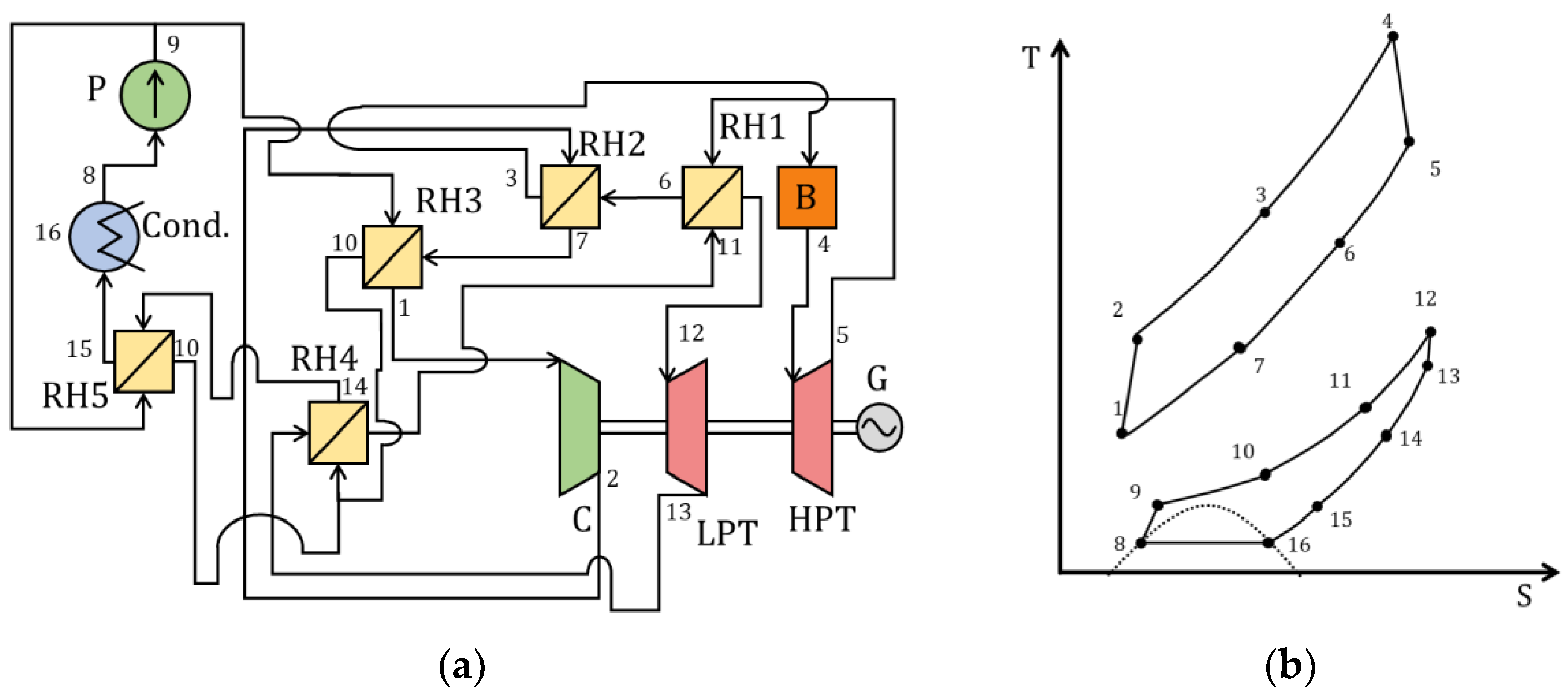
Figure 1. Cycle proposed by Gokhshtein and Verkhivker: (a) schematic diagram; (b) T–S diagram [11]. B—boiler; LPT—low-pressure turbine; HPT—high-pressure turbine; G—generator; Cond.—condenser; P—pump; RH1, RH2, RH3, RH4, RH5—regenerative heat exchangers.
Energies 15 09226 g001
Figure 2. Supercritical CO2 Brayton cycle with regeneration: (a) schematic diagram; (b) T–S diagram [12]. R—reactor; T—turbine; G—generator; RH—regenerative heat exchanger; PC—precooler; C—compressor.
Energies 15 09226 g002
Figure 3. Supercritical CO2 Brayton cycle with reheating: (a) schematic diagram; (b) T–S diagram [12]. R—reactor; LPT—low-pressure turbine; HPT—high-pressure turbine; G—generator; RH—regenerative heat exchanger; PC—precooler; C—compressor.
Energies 15 09226 g003
Figure 4. Supercritical CO2 Brayton cycle with precooling: (a) schematic diagram; (b) T–S diagram [12]. R—reactor; T—turbine; G—generator; RH—regenerative heat exchanger; PC—precooler; IC—internal cooler; C—compressor; RC—high-pressure compressor.
Energies 15 09226 g004
Figure 5. Supercritical CO2 Brayton cycle with partial cooling: (a) schematic diagram; (b) T–S diagram [12]. R—reactor; T—turbine; G—generator; HTR—high-temperature regenerative heat exchanger; LTR—low-temperature regenerative heat exchanger; PC—precooler; CR—gas cooler; LPC—low-pressure compressor; HPC—high-pressure compressor.
Energies 15 09226 g005
Figure 6. Supercritical CO2 Brayton cycle with recompression: (a) schematic diagram; (b) T–S diagram [12]. R—reactor; T—turbine; G—generator; HTR—high-temperature regenerative heat exchanger; LTR—low-temperature regenerative heat exchanger; PC—precooler; MC—main compressor; RC—recompression compressor.
Energies 15 09226 g006
Figure 7. Cascade Brayton cycle with doubled overheating: (a) schematic diagram; (b) T–S diagram [16]. LTH—low-temperature heater; HTH—high-temperature heater; HTT—high-temperature turbine; LTT—low-temperature turbine; G—generator; HTR—high-temperature regenerative heat exchanger; LTR—low-temperature regenerative heat exchanger; PC—precooler; C—compressor.
Energies 15 09226 g007
Figure 8. Rankine cycle with recompression: (a) schematic diagram; (b) T–S diagram [13]. B—boiler; T—turbine; G—generator; HTR—high-temperature regenerative heat exchanger; LTR—low-temperature regenerative heat exchanger; C—compressor; P—pump.
Energies 15 09226 g008
Figure 9. Rankine cycle with regeneration: (a) schematic diagram; (b) T–S diagram [19]. H—heater; T—turbine; G—generator; RH—regenerative heat exchanger; C—condenser; P—pump.
Energies 15 09226 g009
Figure 10. Cascade Rankine cycle: (a) schematic diagram; (b) T–S diagram [19]. HTT—high-temperature turbine; LTT—low-temperature turbine; G—generator; HTR—high-temperature regenerative heat exchanger; LTR—low-temperature regenerative heat exchanger; P—pump; LTH—low-temperature heater; HTH—high-temperature heater.
Energies 15 09226 g010
Figure 11. Split Rankine cycle with regeneration: (a) schematic diagram; (b) T–S diagram [19]. HTT—high-temperature turbine; LTT—low-temperature turbine; G—generator; RH—regenerative heat exchanger; P—pump; LTH—low-temperature heater; HTH—high-temperature heater.
Energies 15 09226 g011
Figure 12. Supercritical CO2 Brayton cycle using liquefied natural gas for precooling: (a) schematic diagram; (b) T–S diagram [21]. B—boiler; T—turbine; C—compressor; LNG-H—LNG heater; RH—regenerative heat exchanger; G—generator.
Energies 15 09226 g012
Figure 13. Supercritical CO2 Brayton cycle with trigeneration based on supercritical carbon dioxide: (a) schematic diagram; (b) T–S diagram [22]. B—boiler; T—turbine; G—generator; HTR—high-temperature regenerative heat exchanger; LTR—low-temperature regenerative heat exchanger; LTH—low-temperature heater; HTH—high-temperature heater; V—valve; LPC—low-pressure compressor; HPC—high-pressure compressor; E—evaporator; GC—gas cooler; PC—precooler.
Energies 15 09226 g013
Figure 14. Supercritical CO2 Rankine with an ejector: (a) schematic diagram; (b) T–S diagram [23]. HTT—high-temperature turbine; HTH—high-temperature heater; LTH—low-temperature heater; P—pump; C—condenser; E—ejector; G—generator.
Energies 15 09226 g014
Figure 15. Supercritical CO2 Brayton cycle with acetone absorption: (a) schematic diagram; (b) T–S diagram [24]. B—boiler; T—turbine; C—compressor; Cr—condenser; P—pump; RH—regenerative heat exchanger; G—generator.
Energies 15 09226 g015
Figure 16. Oxy–fuel energy complex: (a) schematic diagram; (b) T–S diagram [26]. ASU—air separation unit; CC—combustion chamber; GT—gas turbine; RH—regenerative heat exchanger; C—cooler.
Energies 15 09226 g016
Figure 17. SCOC-CC: (a) schematic diagram; (b) T–S diagram [27]. Comp.—compressor; CC—combustion chamber; GT—gas turbine; B—boiler; ST—steam turbine; C—cooler–separator.
Energies 15 09226 g017
Figure 18. MATIANT cycle: (a) schematic diagram; (b) T–S diagram [32]. Comp.—compressor; CC—combustion chamber; LPT—low-pressure turbine; RH—regenerative heat exchanger; HPT—high-pressure turbine; C—cooler.
Energies 15 09226 g018
Figure 19. E-MATIANT cycle: (a) schematic diagram; (b) T–S diagram [34]. Comp.—compressor; CC—combustion chamber; LPT—low-pressure turbine; RH—regenerative heat exchanger; HPT—high-pressure turbine; S—separator; P—pump.
Energies 15 09226 g019
Figure 20. Allam cycle: (a) schematic diagram; (b) T–S diagram [35]. ASU—air separation unit.
Energies 15 09226 g020
Figure 21. SCOC-CC cycle with preliminary cooling of turbine blade refrigerant: (a) schematic diagram; (b) T–S diagram [38]. ASU—air separation unit.
Energies 15 09226 g021
Figure 22. Schematic diagram of SCOC-CC cycle with water injection [38]. ASU—air separation unit.
Energies 15 09226 g022
Figure 23. SCOC cycle with WHR: (a) schematic diagram; (b) T–S diagram [39]. ASU—air separation unit. Comp.—compressor; CC—combustion chamber; GT—gas turbine; ST—steam turbine; RH—regenerative heat exchanger; C—condenser; P—pump.
Energies 15 09226 g023
Figure 24. Allam cycle with WHR: (a) schematic diagram; (b) T–S diagram [40]. ASU—air separation unit.
Energies 15 09226 g024
Figure 25. Allam cycle with cooling by means of LNG and WHR: (a) schematic diagram; (b) T–S diagram [41]. ASU—air separation unit.
Energies 15 09226 g025
Figure 26. Schematic diagram of MATIANT cycle with synthetic methane synthesis [42]. Comp.—compressor; CC—combustion chamber; LPT—low-pressure turbine; HPT—high-pressure turbine; RH—regenerative heat exchanger; S—separator.
Energies 15 09226 g026
Figure 27. Classification of supercritical CO2 cycles by power level and temperature at the turbine input.
Energies 15 09226 g027
Figure 28. High-capacity energy CO2 power cycles technologies in comparison with the current average level and level of the best available technologies.
Energies 15 09226 g028
Figure 29. Technologies of CO2 power cycles for small-capacity power engineering.
Energies 15 09226 g029
Figure 30. Technologies for carbon dioxide microgeneration cycles.
Energies 15 09226 g030
Figure 31. Cost of electric power generated with regeneration CO2 power cycles in comparison with NGCC plants at the cost of CO2 emission quotas of 50 $/ton for large-capacity power cycles.
Energies 15 09226 g031
Figure 32. Cost of electric power generated with regeneration CO2 power cycles in comparison with NGCC.
Energies 15 09226 g032
Figure 33. Cost of electric power generated with regeneration CO2 power cycles at the cost of CO2 emission quotas of 50 $/ton for small-capacity distributed power.
Energies 15 09226 g033
Figure 34. Cost of electric power generated with regeneration CO2 power cycles at the cost of CO2 emission quotas of 100 $/ton for small-capacity distributed power.
Energies 15 09226 g034
Figure 35. Cost of electric power generated with regeneration CO2 power cycles at the cost of CO2 emission quotas of 50 $/ton for microgeneration.
Energies 15 09226 g035
Figure 36. Cost of electric power generated with regeneration CO2 power cycles at the cost of CO2 emission quotas of 100 $/ton for microgeneration.
Energies 15 09226 g036
Table 1. Thermophysical properties of water, air and supercritical carbon dioxide within the typical parameters of modern gas turbine and steam turbine plants.
Type of Thermal Power PlantTemperature and Pressure of Working Fluid for Turbine Inlet/OutletDensity of Working Fluid for Turbine Inlet/Outlet, kg/m3Dynamic Viscosity of Working Fluid for Turbine Inlet/Outlet, ·106 Pa·sSpecific Enthalpy of Working Fluid for Turbine Inlet/Outlet, kJ/kg
Steam turbine540 °C, 23.5 MPa/29 °C, 4 kPa74.6/0.004320.8/0.113324.3/120.9
NGCC1100 °C, 1.3 MPa/515 °C, 0.1 MPa3.3/0.44535.9/369.81610.4/935.2
Supercritical CO2 power plant540 °C, 25 MPa/407 °C, 8 MPa155.8/70.8373.9/318.61019.1/875.3
Table 2. Supercritical CO2 power cycles.
CycleNref, MWTinlet, Tref, °Cη, %Cc, $/kWEs, g/kWhLinks
1Verkhivker and Gokhshtein cycle1000675, 67544.51573453[11]
2Regenerative Brayton cycle1000550–1200, 55042.20878477[12]
3Brayton cycle with reheating1000550–1200, 55043.70901461[12]
4Brayton cycle with cooling1000550–1200, 55041.96869480[12]
5Brayton cycle with partial cooling1000550–1200, 55044.80946450[12]
6Brayton cycle with recompression1000550–1200, 55047.28940426[12]
7Brayton cascade cycle1.4500, 50032.605000618[16]
8Brayton cycle WHR15200–600, 40019.0041191060[17]
9Regenerative Brayton cycle WHR15200–600, 40019.5040771033[17]
10Cascade Brayton cycle WHR15200–600, 40025.004469806[17]
11Recompression Brayton cycle WHR15200–600, 40032.004155629[17]
12Brayton cycle WHR with Kalina cycle0.242268, 26816.0086601259[18]
13Brayton cycle with LNG80300–600, 550521491387[20,21]
14Brayton cycle with acetone absorption10001400, 140056.00960360[24]
15Brayton cycle with trigeneration0.1400–1000, 100078.009000258[22]
16Rankine cycle with recompression1000550, 55043.009505[13]
17Rankine cycle with regeneration10300–500, 40019.9029941012[19]
18Cascade Rankine cycle10300–500, 40023.604870853[19]
19Split Rankine cycle with regeneration10300–500, 40026.003316775[19]
20Rankine cycle with ejector0.01100, 1007.0015,0002877[23]
21MATIANT3001100–1300, 130045.0014004[32]
22E-MATIANT3001100–1700, 130046.0013004[34]
23SCOC-CC3001000–1700, 170049.8017224[27]
24Allam cycle3001100–1300, 1110048.0014524[35]
25SCOC-CC with WHR3001000–1700, 17005418492[39]
26SCOC-CC with preliminary cooling3001100–1700, 170052.8017644[38]
27SCOC-CC with water injection3001100–1700, 170051.8017304[38]
28Allam cycle with WHR3001100–1300, 110049.101524.64[40]
29Allam cycle with LNG and ORC3001100–1300, 110053.001640.764[41]
30MATIANT with methane synthesis1001300, 130043.3738005[42]
Table 3. Reference data for modern high-capacity thermal power plants.
CycleNref, MWη, %Cc, $/kWEs, g/kWhLinks
Reference NGCC300601050336[45]
NGCC with CCS300471029315[46]
NGCC with CO2 cycle30064144940[47]
Table 4. The initial data for the net costs calculation.
q f , kWh/kg13.8
C f for natural gas, $/kg0.4
C f for LNG, $/kg0.8
C e , $/ton50;100
k a 0.1
T o , year23
S n , people/kW0.0002
S n , $/hour12.2
Publisher’s Note: MDPI stays neutral with regard to jurisdictional claims in published maps and institutional affiliations.