
Sludge Gasification Using Iron Bearing Metallurgical Slag as Heat Carrier: Characteristics and Kinetics

Abstract
1. Introduction
2. Material and Methods
2.1. Material
2.2. Methods
3. Results and Discussions
3.1. Characteristics of Slag Heat Carrier
3.2. Sludge Gasification Characteristics Based Slag as Heat Carrier
3.3. Sludge Gasification KineticsUsing Slag as Heat Carrier
4. Conclusions
- (1)
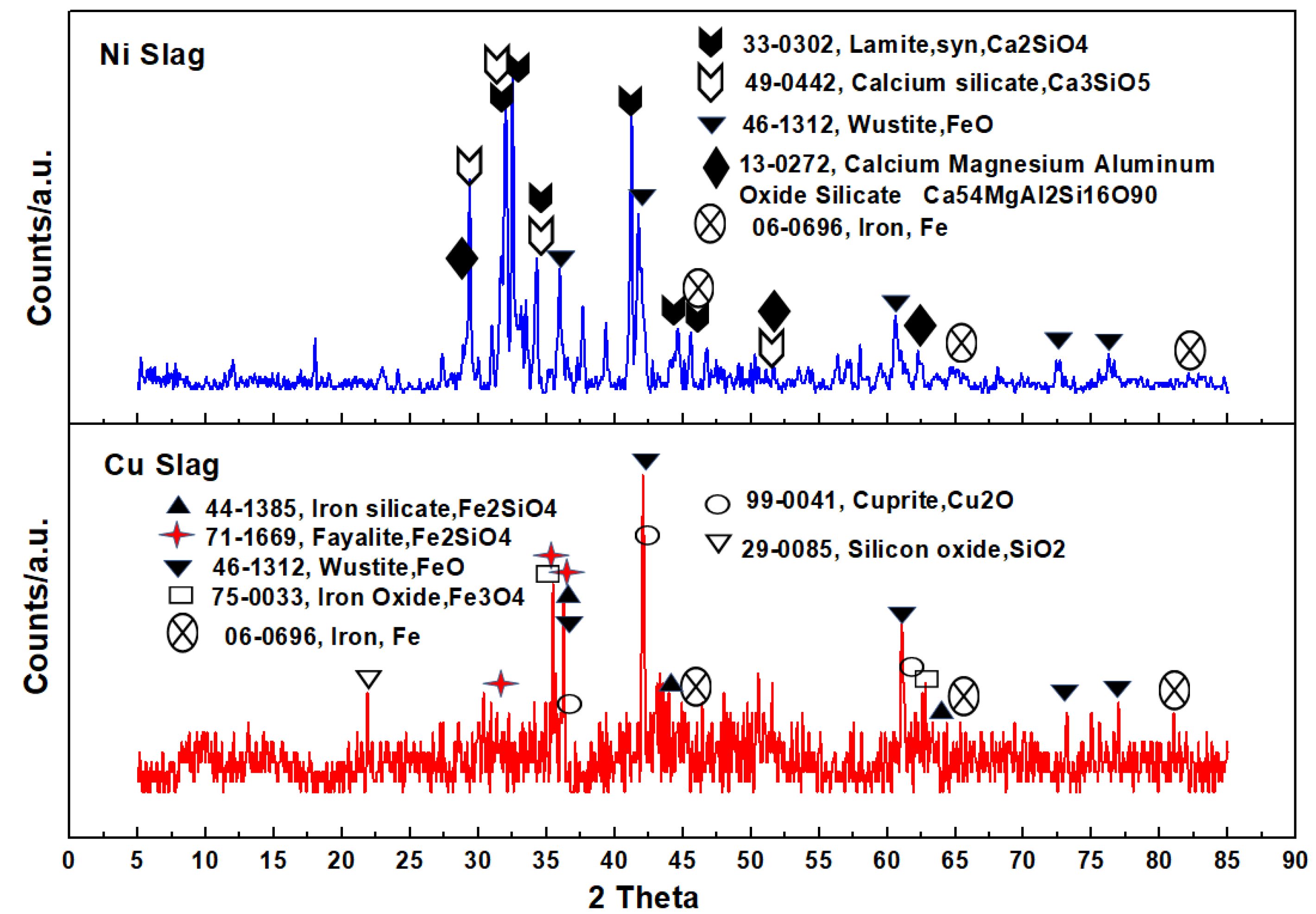
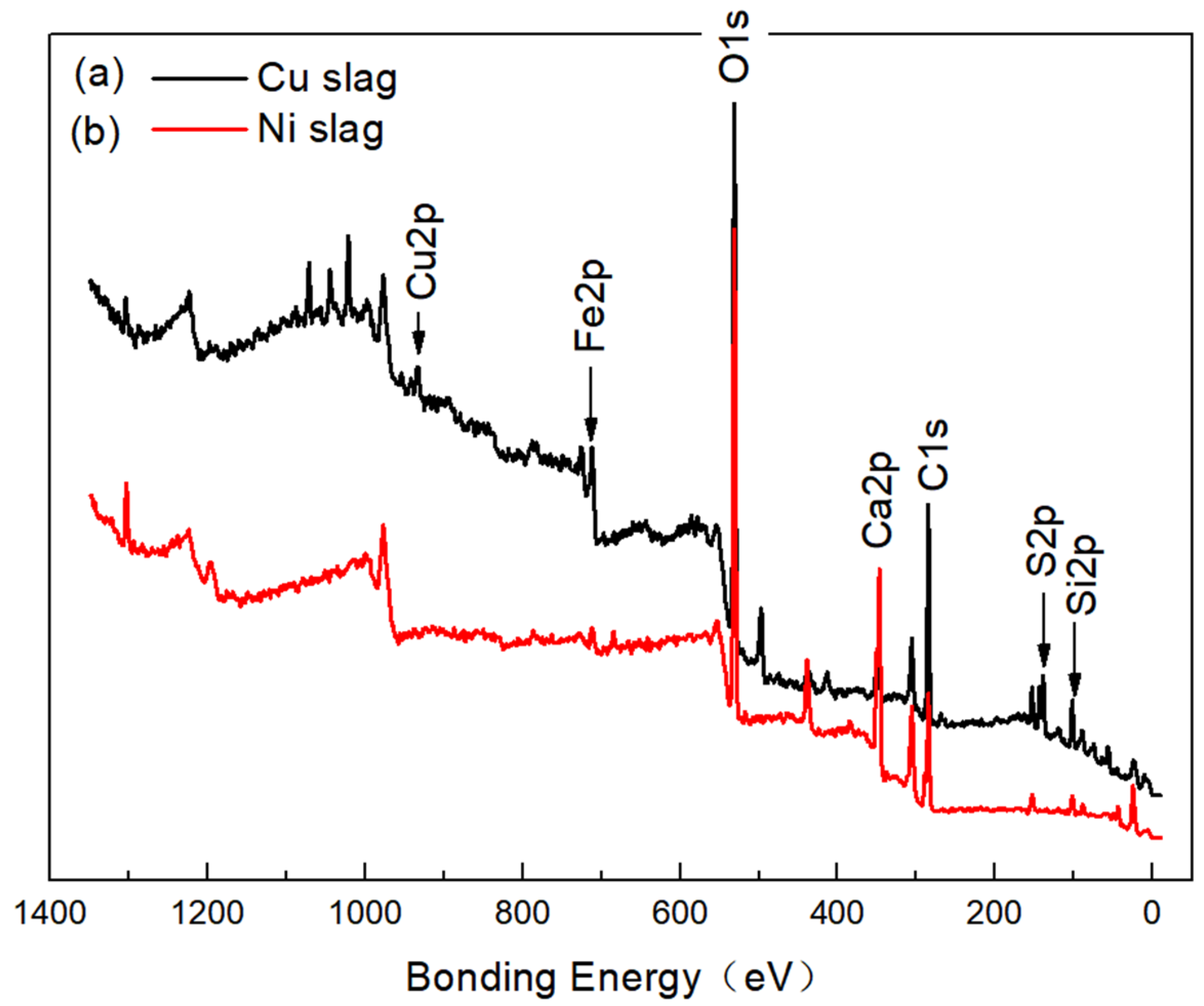
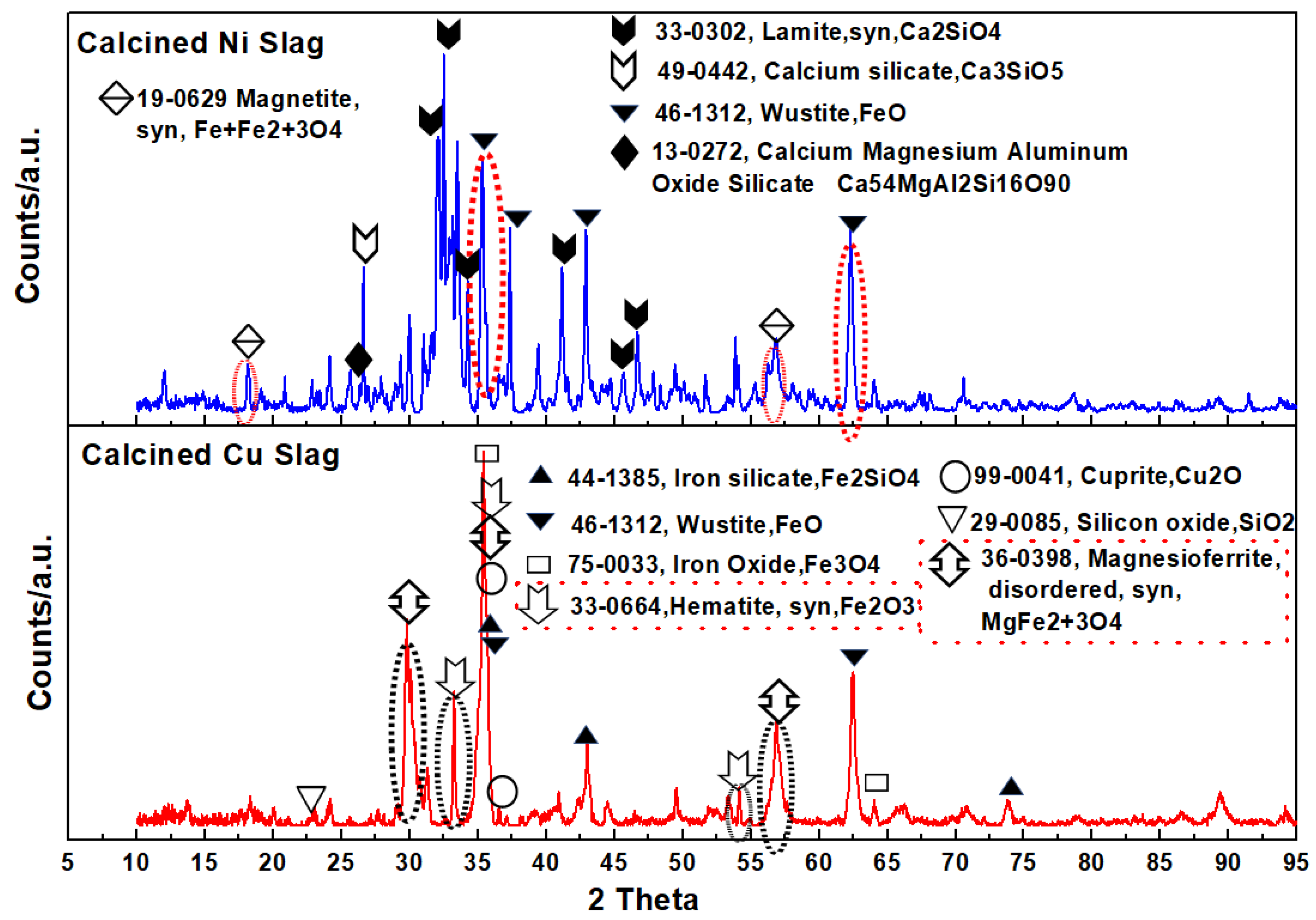
- There were many miscellaneous phases in Cu slag, such as magnetite (Fe3O4), wüstite (FeO), silicon oxide (SiO2), and cuprite (Cu2O). The main phases of Ni slag were lamite (Ca2SiO4) and calcium silicate (Ca3SiO5). The Fe, Si, and Cu content in Cu slag was higher compared to Ni slag. The Ca content in Ni slag was much higher compared to Cu slag.
- (2)
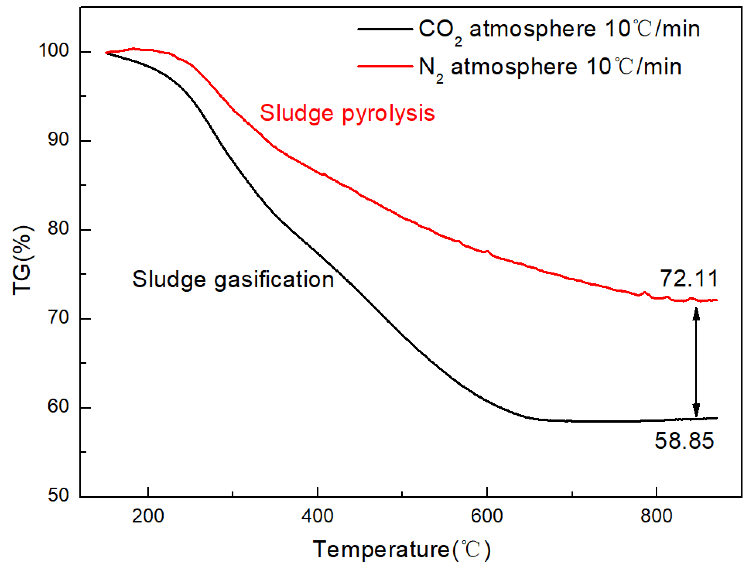
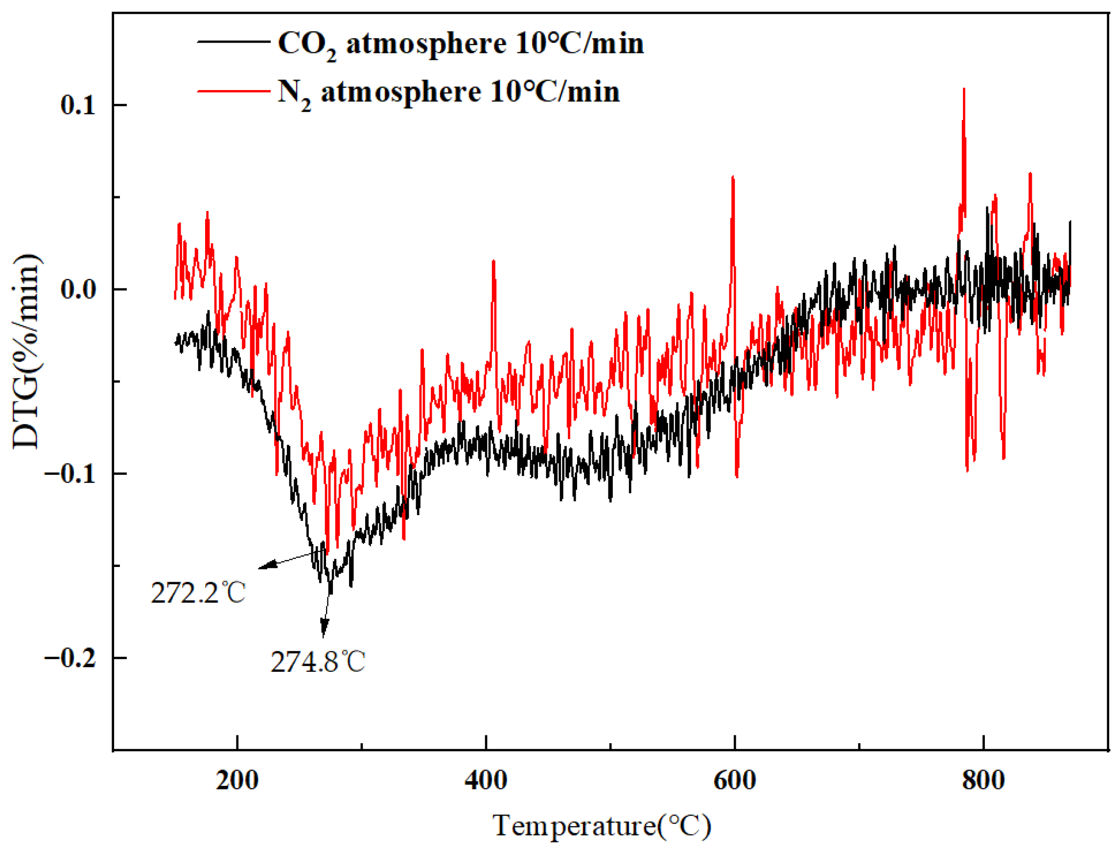
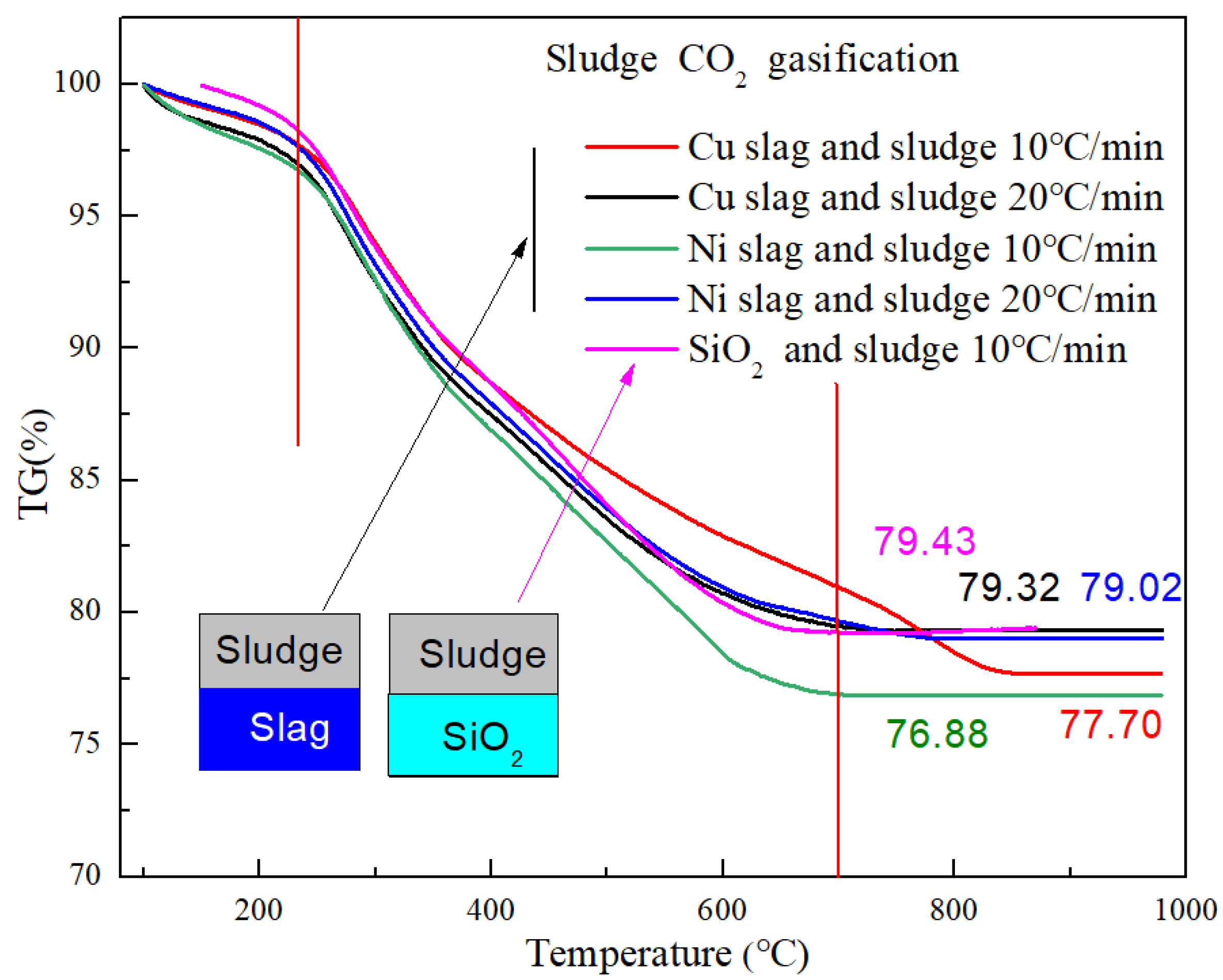
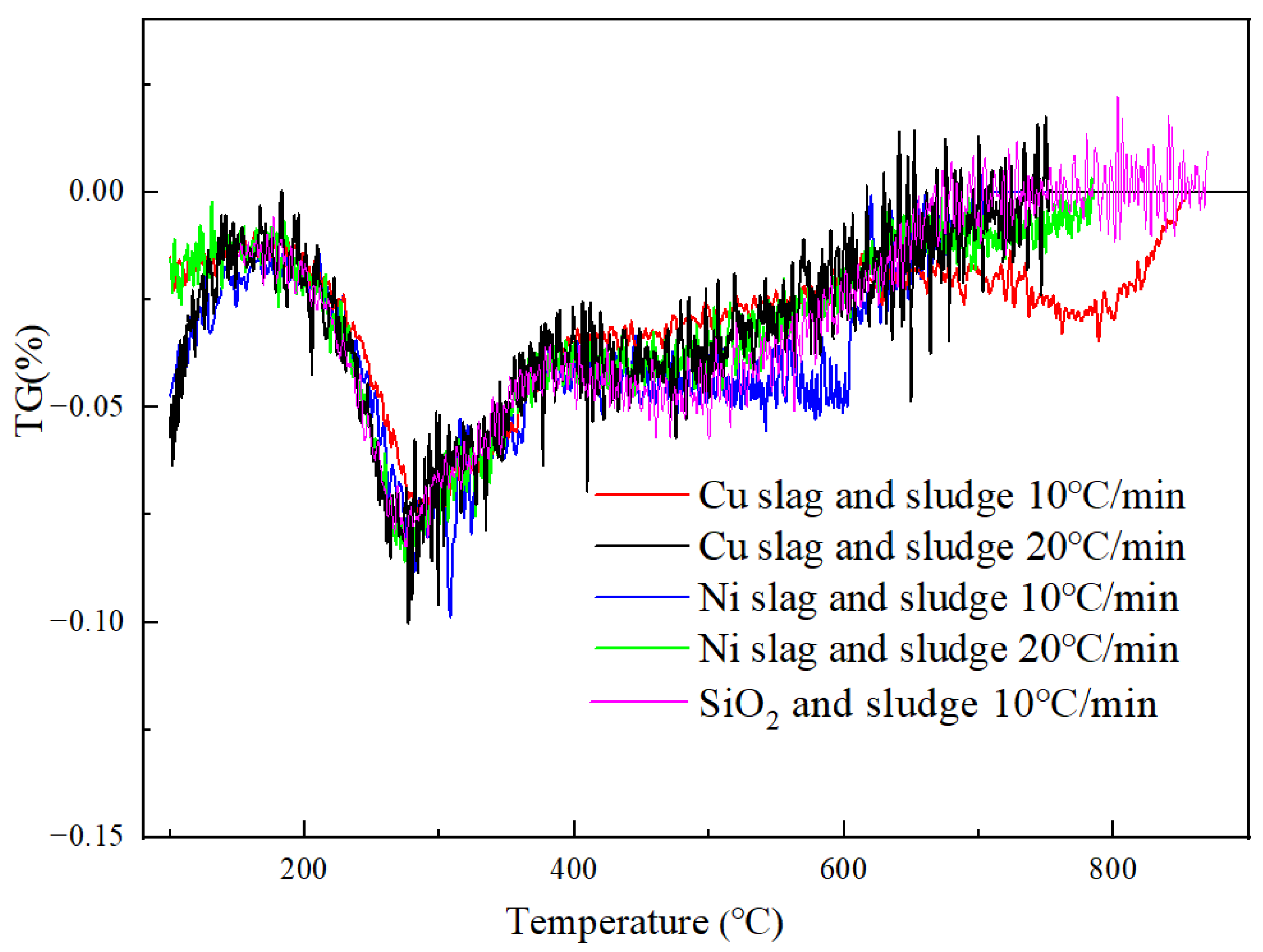
- Metallurgical slag could improve the decomposition rate of the sludge gasification reaction. The conversion ratio was increased by 7.8% and 11.8% when using Cu slag and Ni slag as the heat carriers, respectively. The main catalytic component were Fe3O4 and CaO. The catalytic function of alkali metals in Ni slag was stronger than that of Fe3O4 in Cu slag. Correspondingly, the activation energy of the gasification reaction catalyzed by Cu slag was lower than that catalyzed by Ni slag. Using Cu and Ni slag, activation energy decreased from 21.09 kJ/mol to 17.36 kJ/mol and 17.30 kJ/mol, respectively.
- (3)
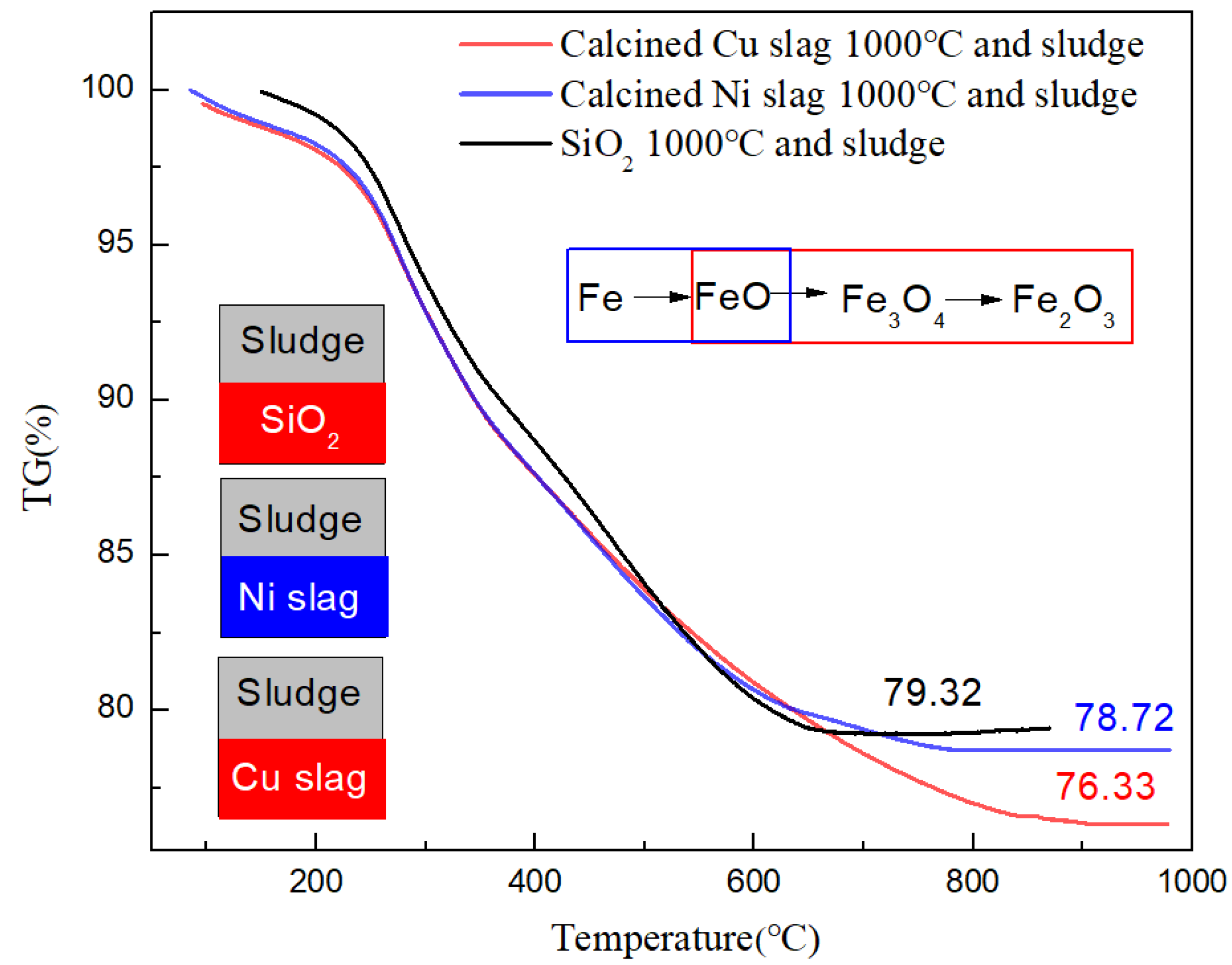
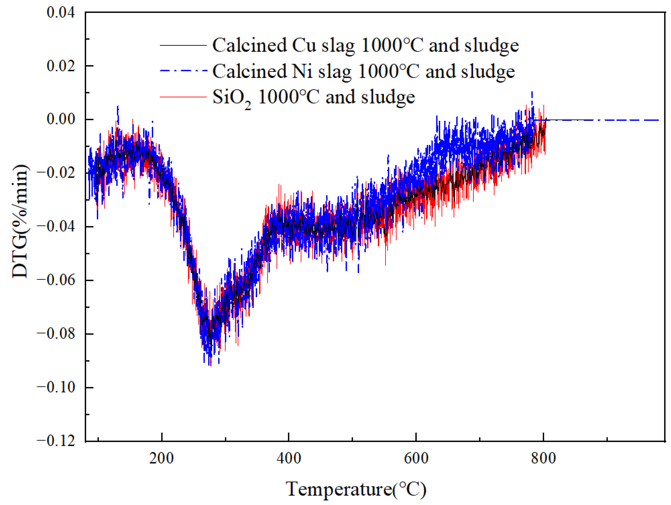
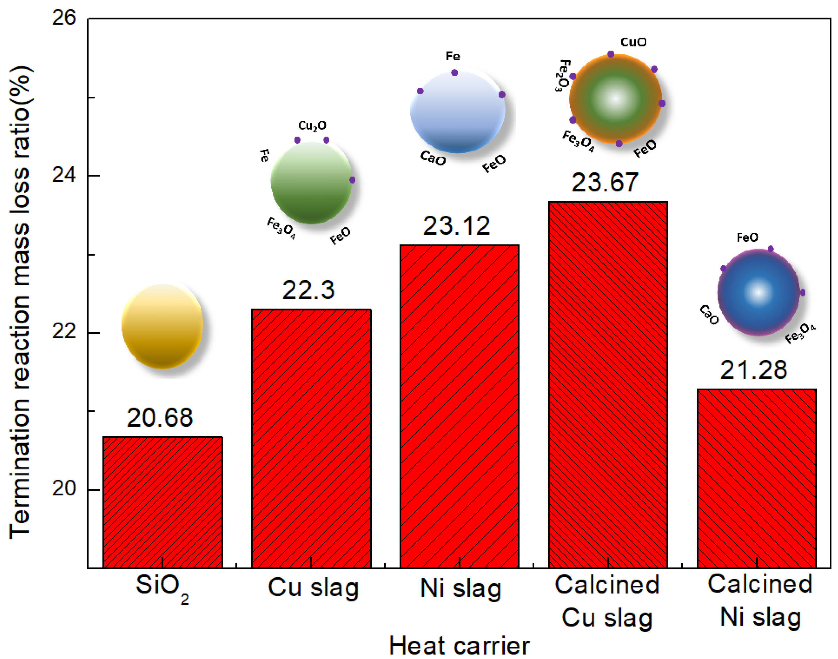
- After modification, the active components changed. Fe2O3 and MgFe2+3O4 were the active components in the modified Cu slag and the catalytic function was enhanced. After modification, CaO remained the active component in Ni slag, but it was weakened by the generation of FeO. In Ni slag, FeO was combined with SiO2 to form olivine, which is an extremely stable structure. The conversion ratio increased by 14.5% and 2.9% when using calcined Cu slag and Ni slag, respectively, compared with sludge gasification using SiO2.
- (4)
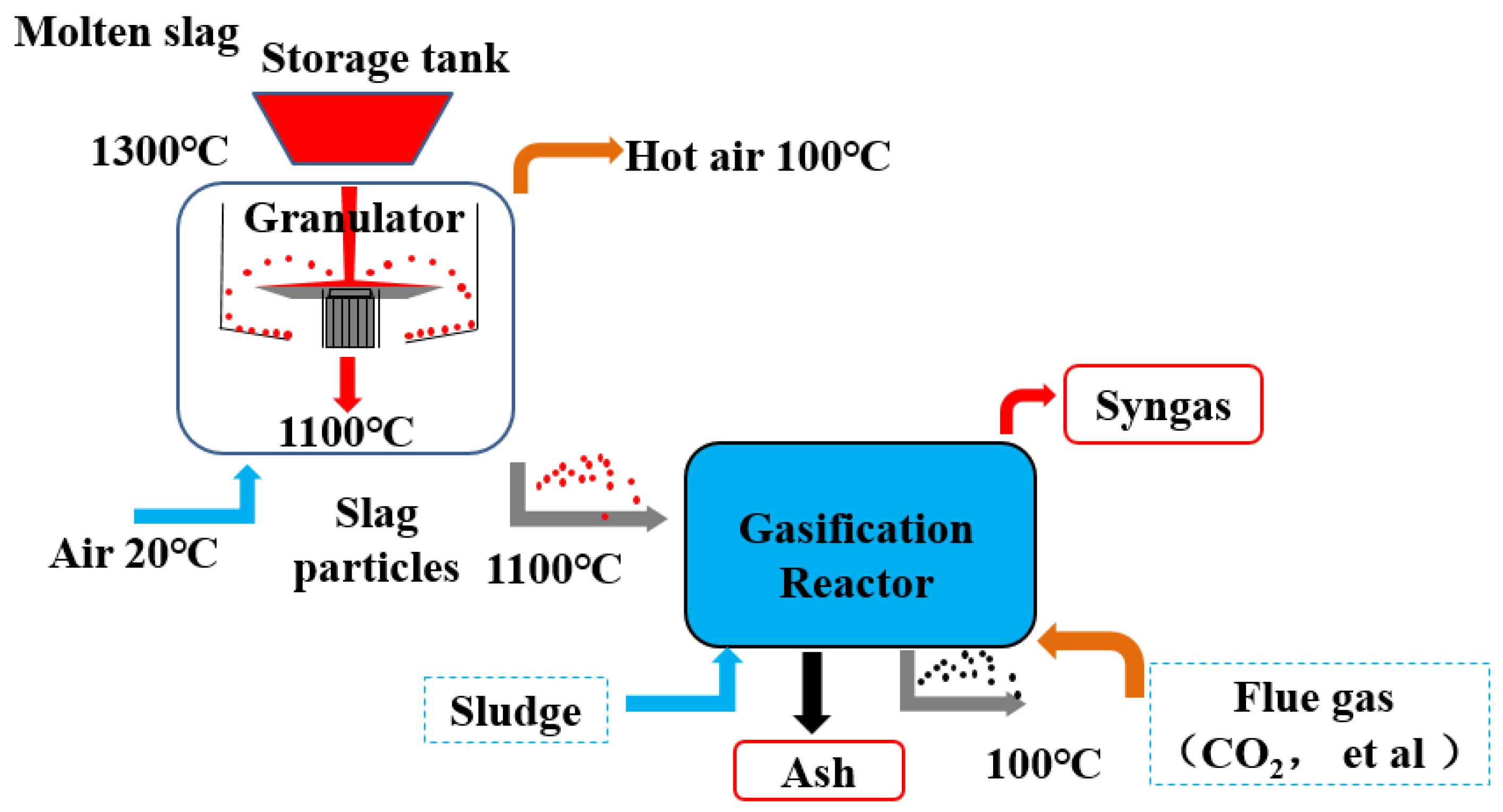
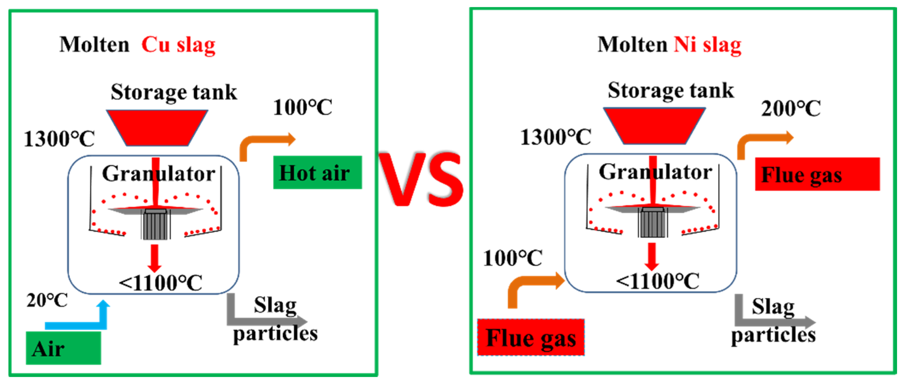
- Oxidation modification is beneficial to the catalytic function of Cu slag but unfavorable to that of Ni slag. Thus, different treatment methods should be applied to Cu slag and Ni slag. Cu slag should be oxidized in the granulation process to transform the internal iron-containing components into magnetite and hematite minerals. On the other hand, Ni slag should not be oxidized in the granulation process.
Author Contributions
Funding
Conflicts of Interest
References
- Fonts, I.; Gea, G.; Azuara, M.; Ábrego, J.; Arauzo, J. Sewage sludge pyrolysis for liquid production: A review. Renew. Sustain. Energy Rev. 2012, 16, 2781–2805. [Google Scholar] [CrossRef]
- Shibata, S. Inventorprocede de Fabrication d’une Huille Combustible a Partir de Boue Digeree; France, 1939. [Google Scholar]
- Taro, S.; Nakorn, W. Kinetic Analyses of Biomass Pyrolysis Using the distributed Activation Energy Model. Fuel 2008, 87, 414–421. [Google Scholar]
- Liu, J.; Huang, Z.; Chen, Z.; Sun, J.; Gao, Y.; Wu, E. Resource utilization of swine sludge to prepare modified biochar adsorbent for the efficient removal of Pb(II) from water. J. Clean. Prod. 2020, 257, 120322. [Google Scholar] [CrossRef]
- Javier, Á.; Jesus, A.; Lius, S.J.; Alberto, G.; Tomas, C.; Mirasol, J.R. Structural changes of sewage sludge char during fixed-bed pyrolysis. Ind. Eng. Chem. Res. 2009, 48, 3211–3221. [Google Scholar]
- Zuo, Z.; Feng, Y.; Li, X.; Luo, S.; Ma, J.; Sun, H.; Bi, X.; Yu, Q.; Zhou, E.; Zhang, J.; et al. Thermal-chemical conversion of sewage sludge based on waste heat cascade recovery of copper slag: Mass and energy analysis. Energy 2021, 235, 121327. [Google Scholar] [CrossRef]
- Shao, J.; Yan, R.; Chen, H.; Yang, H.; Lee, D. Catalytic effect of metal oxides on pyrolysis of sewage sludge. Fuel Process. Technol. 2010, 91, 1113–1118. [Google Scholar] [CrossRef]
- Mu’azu, N.D.; Jarrah, N.; Zubair, M.; Alagha, O. Removal of phenolic compounds from water using sewage sludge-based activated carbon adsorption: A review. Int. J. Environ. Res. Public Health 2017, 14, 1094. [Google Scholar] [CrossRef]
- Bora, A.P.; Gupta, D.P.; Durbha, K.S. Sewage sludge to bio-fuel: A review on the sustainable approach of transforming sewage waste to alternative fuel. Fuel 2020, 259, 116262. [Google Scholar] [CrossRef]
- Guo, J.; Zheng, L.; Li, Z. Microwave drying behavior, energy consumption, and mathematical modeling of sewage sludge in a novel pilot-scale microwave drying system. Sci. Total Environ. 2021, 777, 146109. [Google Scholar] [CrossRef]
- Zhang, H.; Bao, L.; Chen, Y.; Xuan, W.; Yuan, Y. Efficiency improvements of the CO-H2 mixed gas utilization related to the molten copper slag reducing modification. Process Saf. Environ. Prot. 2021, 146, 292–299. [Google Scholar] [CrossRef]
- Zhang, B.; Zhang, T.; Niu, L.P.; Liu, N.; Dou, Z.; Li, Z. Moderate dilution of copper slag by natural gas. JOM 2017, 70, 47–52. [Google Scholar] [CrossRef]
- Guo, Z.; Zhu, D.; Pan, J.; Zhang, F. Innovative methodology for comprehensive and harmless utilization of waste copper slag via selective reduction-magnetic separation process. J. Clean. Prod. 2018, 187, 910–922. [Google Scholar] [CrossRef]
- Meng, X.; Li, Y.; Wang, H.; Yang, Y.; McLean, A. Effects of Na2O additions to copper slag on iron recovery and the generation of ceramics from the non-magnetic residue. J. Hazard. Mater. 2020, 399, 122845. [Google Scholar] [CrossRef] [PubMed]
- Gorai, B.; Jana, R.K. Premchand Characteristics and utilisation of copper slag—A review. Resour. Conserv. Recycl. 2003, 39, 299–313. [Google Scholar] [CrossRef]
- Gao, C.; Yu, W.; Zhu, Y.; Wang, M.; Tang, Z.; Du, L.; Hu, M.; Fang, L.; Xiao, X. Preparation of porous silicate supported micro-nano zero-valent iron from copper slag and used as persulfate activator for removing organic contaminants. Sci. Total Environ. 2021, 754, 142131. [Google Scholar] [CrossRef]
- Li, H.; Zhang, W.; Wang, J.; Yang, Z.; Li, L.; Shih, K. Copper slag as a catalyst for mercury oxidation in coal combustion flue gas. Waste Manag. 2018, 74, 253–259. [Google Scholar] [CrossRef]
- Wang, Q.; Li, Z.; Li, D.; Tian, Q.; Guo, X.; Yuan, Z.; Zhao, B.; Wang, Z.; Wang, Y.; Qu, S.; et al. A Method of High-quality Silica Preparation from Copper Smelting Slag. Jom 2020, 72, 2676–2685. [Google Scholar] [CrossRef]
- Zuo, Z.; Yu, Q.; Luo, S.; Zhang, J.; Zhou, E. Effects of CaO on two-step reduction characteristics of copper slag using biochar as reducer: Thermodynamic and kinetics. Energy Fuels 2020, 34, 491–500. [Google Scholar] [CrossRef]
- Gerasimov, G.; Khaskhachikh, V.; Potapov, O.; Dvoskin, G.; Kornileva, V.; Dudkina, L. Pyrolysis of sewage sludge by solid heat carrier. Waste Manag. 2019, 87, 218–227. [Google Scholar] [CrossRef]
- Luo, S.; Fu, J.; Zhou, Y.; Yi, C. The production of hydrogen-rich gas by catalytic pyrolysis of biomass using waste heat from blast-furnace slag. Renew. Energy 2017, 101, 1030–1036. [Google Scholar] [CrossRef]
- Li, P. Thermodynamic analysis of waste heat recovery of molten blast furnace slag. Int. J. Hydrog. Energy 2017, 42, 9688–9695. [Google Scholar] [CrossRef]
- Zhang, Q.; Liu, H.; Zhang, X.; Lu, G.; Wang, J.; Hu, H.; Li, A.; Yao, H. Effect of Fe/Ca-based composite conditioners on syngas production during different sludge gasification stages: Devolatilization, volatiles homogeneous reforming and heterogeneous catalyzing. Int. J. Hydrog. Energy 2017, 42, 29150–29158. [Google Scholar] [CrossRef]
- Widayatno, W.B.; Guan, G.; Rizkiana, J.; Hao, X.; Wang, Z.; Samart, C.; Abudula, A. Steam reforming of tar derived from Fallopia Japonica stem over its own chars prepared at different conditions. Fuel 2014, 132, 204–210. [Google Scholar] [CrossRef]
- Huang, Z.; Xu, G.; Deng, Z.; Zhao, K.; He, F.; Chen, D.; Wei, G.; Zheng, A.; Zhao, Z.; Li, H. Investigation on gasification performance of sewage sludge using chemical looping gasification with iron ore oxygen carrier. Int. J. Hydrog. Energy 2017, 42, 25474–25491. [Google Scholar] [CrossRef]
- Ma, Z.; Gao, N.; Xie, L.; Li, A. Study of the fast pyrolysis of oilfield sludge with solid heat carrier in a rotary kiln for pyrolytic oil production. J. Anal. Appl. Pyrolysis 2014, 105, 183–190. [Google Scholar] [CrossRef]
- Al-Zareer, M.; Dincer, I.; Rosen, M.A. Analysis and assessment of a hydrogen production plant consisting of coal gasification, thermochemical water decomposition and hydrogen compression systems. Energy Convers. Manag. 2018, 157, 600–618. [Google Scholar] [CrossRef]
- Zuo, Z.; Luo, S.; Liu, S.; Zhang, J.; Yu, Q.; Bi, X. Thermokinetics of mass-loss behavior on direct reduction of copper slag by waste plastic char. Chem. Eng. J. 2021, 405, 126671. [Google Scholar] [CrossRef]
- Feng, Y.; Yang, Q.; Zuo, Z.; Luo, S.; Ren, D.; Lin, H. Study on preparation of oxygen carrier using copper slag as precursor. Front. Energy Res. 2021, 9, 736. [Google Scholar] [CrossRef]
- Sun, Y.; Zhang, Z.; Liu, L.; Wang, X. Two-stage high temperature sludge gasification using the waste heat from hot blast furnace slags. Bioresour. Technol. 2015, 198, 364–371. [Google Scholar] [CrossRef]
- Zhao, L.; Wang, H.; Qing, S.; Liu, H. Characteristics of gaseous product from municipal solid waste gasification with hot blast furnace slag. J. Nat. Gas Chem. 2010, 19, 403–408. [Google Scholar] [CrossRef]
- Luo, S.; Wang, J.; Guo, X.; Liu, Z.; Sun, W. The production of hydrogen-rich gas by wet sludge gasification using waste heat of blast-furnace slag: Mass and energy balance analysis. Int. J. Hydrog. Energy 2019, 44, 5171–5175. [Google Scholar] [CrossRef]
- Deng, S.; Hu, J.; Wang, H.; Li, J.; Hu, W. Catalytic gasification of pre-calcined copper slag and biomass mixture. Chin. J. Environ. Eng. 2013, 7, 3148–3152. [Google Scholar]
- Zhao, L.; Hu, J.; Wang, H.; Liu, H.; Qing, S.; Li, L. Influence of Pre-calcined Copper-containing Slag on Catalytic Pyrolysis Kinetics of Biomass. Chin. J. Process Eng. 2010, 10, 726–731. [Google Scholar]


| FeO | SiO2 | TFe | CaO | Mfe | Al2O3 | Zn | Na | MgO | Cu |
|---|---|---|---|---|---|---|---|---|---|
| 24.63 | 31.77 | 27.19 | 9.58 | 7.70 | 6.24 | 4.85 | 3.02 | 2.53 | 0.68 |
| CaO | Tfe | SiO2 | MgO | FeO | Mfe | Mn | TiO2 | Cu | Ni |
|---|---|---|---|---|---|---|---|---|---|
| 47.28 | 16.42 | 13.73 | 7.15 | 6.67 | 6.05 | 3.45 | 0.79 | 0.013 | <0.01 |
| Sample | Moisture | Volatile | Ash | Fixed Carbon |
|---|---|---|---|---|
| Municipal sludge | 0.01 | 52.46 | 40.23 | 7.30 |
| Sample | Name | Start BE | Peak BE | End BE | Height CPS | FWHM (eV) | Area (P) CPS. eV |
|---|---|---|---|---|---|---|---|
| Cu slag | Si2p | 109.76 | 102.06 | 94.86 | 3261.75 | 1.75 | 6695.26 |
| S2p | 174.76 | 162.82 | 156.86 | 387.82 | 3.04 | 2406.07 | |
| C1s | 297.76 | 284.8 | 278.86 | 16,680.03 | 1.26 | 27,618.2 | |
| Ca2p | 359.76 | 347.35 | 339.86 | 3143.93 | 1.62 | 11,346.11 | |
| O1s | 544.76 | 531.06 | 524.86 | 33,295.91 | 2.32 | 85,416.3 | |
| Fe2p | 739.71 | 711.09 | 699.91 | 4352.76 | 4.19 | 40,033.9 | |
| Ni2p | 887.71 | 862.3 | 843.91 | 409.43 | 0.12 | 7407.4 | |
| Cu2p | 966.71 | 932.34 | 924.91 | 3363.35 | 2.1 | 22,266.04 | |
| Ni slag | Si2p | 109.41 | 102.03 | 94.51 | 896.45 | 2.46 | 2533.86 |
| S2p | 174.41 | 169.1 | 156.51 | 178.68 | 0.15 | 668.68 | |
| C1s | 297.41 | 284.8 | 278.51 | 7267.74 | 1.54 | 16,835.57 | |
| Ca2p | 359.41 | 347.03 | 339.51 | 12177.8 | 1.84 | 38,357.95 | |
| O1s | 544.41 | 531.27 | 524.51 | 25,476.15 | 2.35 | 68,628.93 | |
| Fe2p | 739.36 | 710.81 | 699.56 | 1014 | 4.29 | 11,257.13 | |
| Ni2p | 883.36 | 863.02 | 843.56 | 330.64 | 0.31 | 5168.47 | |
| Cu2p | 966.36 | 940.41 | 924.56 | 404.94 | 0.52 | 5524.79 |
| No | Heat Carrier | Heating Rate (°C/min) | Atmosphere | Temperature Region of Maximum Mass loss (°C) | R2 | Activation Energy (kJ/mol) | Reaction Coefficient | |
|---|---|---|---|---|---|---|---|---|
| 1 | - | 10 | N2 | 247 | 352 | 0.998 | 21.18 | 2 |
| 2 | - | 10 | CO2 | 237 | 347 | 0.998 | 21.93 | 2 |
| 3 | SiO2 | 10 | CO2 | 227 | 302 | 0.995 | 21.09 | 0.5 |
| 4 | Cu slag | 20 | CO2 | 237 | 352 | 0.984 | 17.93 | 1 |
| 5 | Cu slag | 10 | CO2 | 262 | 367 | 0.993 | 17.36 | 2 |
| 6 | Ni slag | 20 | CO2 | 247 | 347 | 0.995 | 18.10 | 1.5 |
| 7 | Ni slag | 10 | CO2 | 252 | 352 | 0.996 | 17.30 | 2 |
| 8 | Calcined-Cu slag | 10 | CO2 | 247 | 372 | 0.998 | 14.53 | 2 |
| 9 | Calcined-Ni slag | 10 | CO2 | 262 | 372 | 0.993 | 17.86 | 2 |
Publisher’s Note: MDPI stays neutral with regard to jurisdictional claims in published maps and institutional affiliations. |
© 2022 by the authors. Licensee MDPI, Basel, Switzerland. This article is an open access article distributed under the terms and conditions of the Creative Commons Attribution (CC BY) license (https://creativecommons.org/licenses/by/4.0/).
Share and Cite
Zuo, Z.; Jing, T.; Wang, J.; Dong, X.; Chen, Y.; Luo, S.; Zhang, W. Sludge Gasification Using Iron Bearing Metallurgical Slag as Heat Carrier: Characteristics and Kinetics. Energies 2022, 15, 9223. https://doi.org/10.3390/en15239223
Zuo Z, Jing T, Wang J, Dong X, Chen Y, Luo S, Zhang W. Sludge Gasification Using Iron Bearing Metallurgical Slag as Heat Carrier: Characteristics and Kinetics. Energies. 2022; 15(23):9223. https://doi.org/10.3390/en15239223
Chicago/Turabian StyleZuo, Zongliang, Tian Jing, Jinmeng Wang, Xinjiang Dong, Yishan Chen, Siyi Luo, and Weiwei Zhang. 2022. "Sludge Gasification Using Iron Bearing Metallurgical Slag as Heat Carrier: Characteristics and Kinetics" Energies 15, no. 23: 9223. https://doi.org/10.3390/en15239223
APA StyleZuo, Z., Jing, T., Wang, J., Dong, X., Chen, Y., Luo, S., & Zhang, W. (2022). Sludge Gasification Using Iron Bearing Metallurgical Slag as Heat Carrier: Characteristics and Kinetics. Energies, 15(23), 9223. https://doi.org/10.3390/en15239223