Article

Safety Characteristics of Lithium-Ion Batteries under Dynamic Impact Conditions

1
College of Mechanical and Vehicle Engineering, Chongqing University, Chongqing 400030, China
2
School of Vehicle Engineering, Chongqing University of Technology, Chongqing 401331, China
*
Author to whom correspondence should be addressed.
Energies 2022, 15(23), 9148; https://doi.org/10.3390/en15239148
Submission received: 16 November 2022 / Revised: 27 November 2022 / Accepted: 29 November 2022 / Published: 2 December 2022

Abstract

:
With the rapid development of electric vehicles, the safety accidents caused by the damage and failure of lithium-ion batteries under mechanical load are increasing gradually, which increases the significance of collision safety in lithium-ion batteries. The failure threshold of the cell in a free state is different from that of the cells in the module. Therefore, the safety characteristics of cells and modules under vertical dynamic impact conditions were studied in this paper. Lithium iron phosphate (LiFePO4) batteries and assembled 2-in-10 series modules with a 100% state of charge (SOC) were tested. Analyses included the voltage, temperature, and mechanical behavior of test samples under different impact loads, extrusion positions, and indenter shapes. The results showed that the damage behavior of a battery was closely related to the contact shape, contact area, and contact position. A smaller contact area led to greater deformation; moreover, the contact area being closer to the edge position meant greater deformation and weaker load-carrying capacity. The load-carrying capacity of the cell in a free state was weaker than that of the module, but the failure threshold of the cell in a free state was higher than that of the module. It can be concluded that the failure threshold of the cell cannot reflect the failure threshold of the module.

1. Introduction

Lithium-ion batteries have been widely used in electric vehicles due to their high energy density and long life cycle. With the increasing number of electric vehicles, an increase in combustion and explosion accidents of electric vehicles was also observed [1,2,3]. During vehicle operation, it is difficult to completely avoid vehicle collisions and projectile impact events. For electric vehicles, most combustion and explosion accidents result in a thermal runaway (TR) of the lithium-ion battery after the collision, which usually coincides with the presence of obvious scratches or deformation caused by collisions on the bottom of the electric vehicle, where the batteries are usually located [4,5,6]. Therefore, it is necessary to study the safety properties of lithium ion batteries under dynamic impact conditions.
The battery pack, when placed at the bottom of the electric vehicle, typically receives no significant shielding from the ground. Therefore, the battery pack is prone to deformation during underpinnings or collisions [7,8]. Slight deformation may cause the capacity to decrease quickly and the micro internal short circuit [9,10]. Excessive deformation may cause a major short circuit inside the battery and result in a TR event. There are three main types of bottom collisions for electric vehicles: (1) a battery pack pierced by sharp objects on the road; (2) a foreign object stuck between the road and the battery pack; and (3) a battery pack impacted or extruded by foreign bodies directly [11,12,13]. The third form is more common than the first two. Currently, mechanical safety testing methods for batteries include three-point bending, extrusion, needling, and drop-weight tests [14,15,16]. Through three-point bending and static extrusion tests, the intrinsic safety characteristics of the battery can be studied intuitively. The drop-weight impact test can better simulate the dynamic damage behavior of the battery during the collision process. Xia et al. [17] conducted dynamic impact tests in different directions, with soft-pack batteries holding differing states of charge (SOC). The results showed that the load-carrying capacities of the modules in the X and Y directions were twice as high as the carrying capacity of those same modules in the Z direction, and the load-carrying capacity of the modules was stronger than that of the cells. Yang et al. [11] analyzed the key characteristics of foreign objects on the road and studied the deformation behavior of cells under quasi-static extrusion conditions. Chen et al. [18] conducted a dynamic impact study on square lithium-ion batteries and found that the indentation depth under dynamic impact conditions was much smaller than that under quasi-static extrusion. Sergiy et al. [19] studied the failure behavior of soft-pack batteries under high-speed impact with a cylindrical extrusion intender, indicating that the critical impact speed triggering TR of a typical soft-pack battery is 25 cm/s. Zhu et al. [20] studied battery failure behaviors during quasi-static extrusion with cylindrical and wedge-shaped punches, indicating that the main mode of battery failure caused by a cylindrical punch is extrusion, while a wedge-shaped punch results in shearing failures. According to previous research, it can be seen that the mechanical safety of battery packs is not only related to the extrusion speed and energy, but also related to the shape of the extrusion punch, the extrusion angle, and the extrusion position [21,22]. More effective protection methods and structural optimization methods require detailed study [23,24].
This paper focuses on the influence of extrusion punch shape and extrusion position on the safety of the cell and module during dynamic impact tests. To more closely replicate real-world conditions, commercial high-capacity batteries with 100% SOC were used as the test samples. The mechanical–electrical–thermal behaviors of the batteries and modules under dynamic impact conditions were analyzed. By analyzing the failure behavior of the battery and module under different dynamic impact conditions, effective data can be provided for the structural design of the battery pack.

2. Experimental Methods

2.1. Experimental Samples

The experimental samples of the battery and module are shown in Figure 1. For the samples, the cathode material is lithium iron phosphate, the anode material is graphite, the nominal capacity is 120 Ah, and the size is 148 mm × 71 mm × 110 mm. The module consists of 10 batteries assembled in series into a module, and then two small modules assembled in parallel into a large module. To obtain the safety properties of the battery under extreme conditions, the SOCs of the test samples are 100%. The X, Y, and Z directions of the battery and module are defined according to the driving direction and the installation state of the battery in the vehicle, as shown in Figure 1. Z+ was defined as the direction of the electrode tab, with Z− being the direction of the “bottom” of the battery.
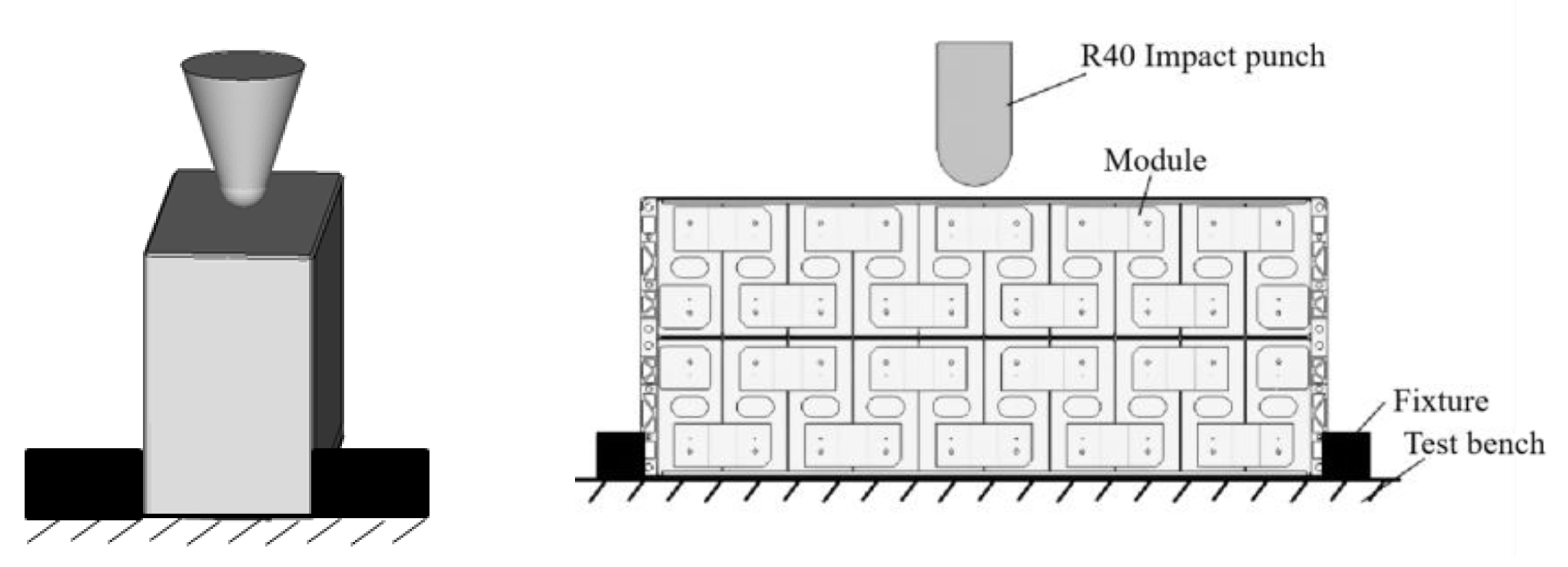
Figure 2 shows a fixed-mode diagram of the battery cell and module. The battery and module are simply fixed at the bottom to ensure that the samples can deform freely under dynamic impact. To replicate a collision scenario at the bottom of the electric vehicle in actual traffic conditions, such as a sharp object puncture, stone impact, or underpinning collision, and study the influence of different foreign body shapes on the safety of the battery under dynamic impact conditions, the conical and cylindrical indenters were selected to test the battery cell and module. By simplifying the objects that may collide on the road and referring to the literature [7], the indenter size was chosen with a conical punch radius of 10 mm and a cylindrical punch radius of 40 mm.

2.2. Experimental Conditions

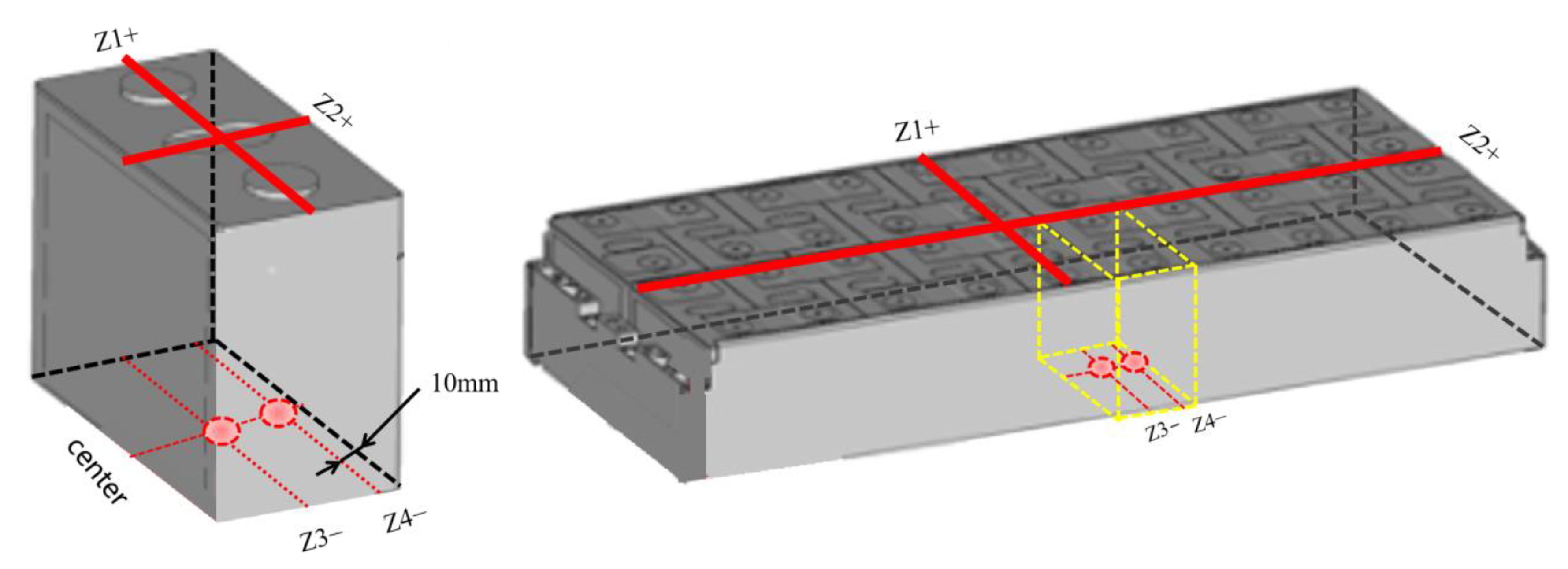
Four impact positions (designated Z1+, Z2+, Z3−, and Z4−) were selected to study the safety properties of the samples during the dynamic impact process. Figure 3 illustrates the impact position of the samples. Among them, Z1+ and Z2+ are at the same end as the electrode tab, indicating the transverse and longitudinal dynamic blunt impact positions of the cylindrical extrusion punch. Z3− and Z4− are on the “bottom side,” with Z3− at the center and Z4− at the junction of the longitudinal center line and the line 10 mm away from the edge. The cylindrical indenter was selected in the Z+ direction to simulate the mutual extrusion between the battery or module and the pack shell under the condition of underpinning by a large foreign object. The conical indenter was selected for Z− direction testing to simulate the battery and module being punctured by conical foreign objects beneath the vehicle.
Table 1 lists the experimental conditions for the samples. By using the dynamic impact models that were previously built by our team, the experimental impact velocity was determined by the maximum deformation in the Z direction reaching 10%. The tests were repeated three times under each working condition and averaged. The voltage, temperature, impact load, and acceleration of the battery cell and module were collected. To ensure that the samples were safe during the treatment and transportation processes, voltage, and internal resistance were continuously monitored for 48 h after the tests were performed. Electrolyte leakage and TR events were also recorded when observed. According to previous research, the lithium ion battery used in the tests may not occur thermal runaway under the condition of 10% deformation. Thus, electrolyte leakage and cracking of the shell were also considered as failures. All other treatment methods after the extrusion of the battery were performed in accordance with China National Standard GB38031-2020.
Impact energy and impact velocity were obtained by using the following equations:
E = m g h
v = 2 g h
where m is the mass of the drop-weight, g is the gravitational constant, and h is the drop height.

2.3. Experimental Equipment

The above tests were carried out on the drop-weight test system, as shown in Figure 4. The test equipment includes the test platform, indenter, mass block, K-type thermo-couples, force sensor, and high-speed camera. The tests were carried out in free-falling impact mode. The effective impact height ranged from 0 to 3500 mm. Different impact energies were achieved by adjusting the mass block and impact height. Thermo-couples were used to monitor battery temperature. Voltage was monitored with a standard voltage sensor.

3. Results and Discussion

3.1. Drop-Weight Impact Tests with Batteries

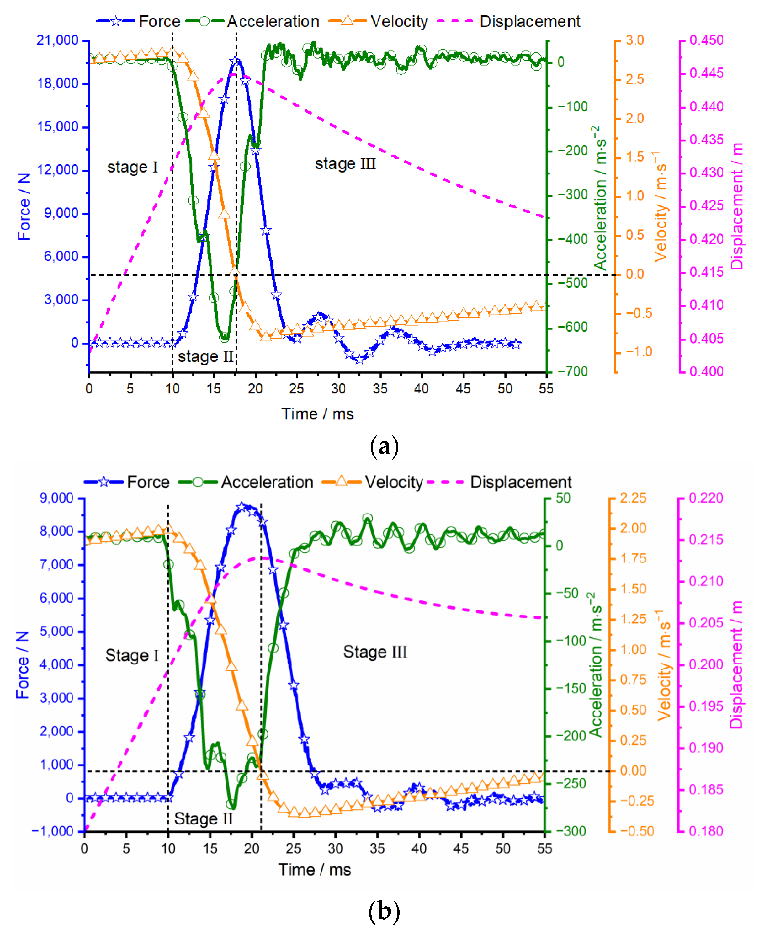
Figure 5 shows the Z+ test results. The velocity-time curve can be obtained by integrating the acceleration-time curve of the indenter. The displacement-time curve can be obtained by integrating the velocity-time curve. According to the curves in Figure 5, the dynamic impact process of the battery during blunt force impacts can be divided into three stages: initial contact stage, extrusion deformation stage, and rebound stage. At the beginning of the initial contact stage, the battery contacts the indenter, the force is 0, and the velocity of the indenter rises rapidly. Due to the gap between the battery, the ground, and the stiffness of the electrode tab, the battery is compacted at the beginning of the extrusion deformation stage. As the resistance of the indenter increases, the reverse acceleration increases first and then decreases. At the end of the extrusion deformation stage, the deformation of the battery reaches its maximum, and the velocity of the indenter decreases to 0 m/s. Due to the energy loss of the indenter, the deformation of the battery begins to rebound. During the rebound stage, the force decreases, the reverse acceleration decreases, and the reverse velocity increases. After repeated cycles in the rebound stage, the energy of the indenter is depleted and restored to a static state.
To compare the damage of different impact positions on the battery, maximum deformation, force, and impact energy were considered. The maximum deformation is obtained by subtracting the displacement of the indenter in the initial contact stage from the maximum displacement. Through the displacement-time curve, it can be concluded that the maximum deformations of the battery along the Z1+ and Z2+ impact vectors were 13.7 mm and 13.3 mm, respectively. The maximum force in the Z1+ orientation was 2.24 times that observed in the Z2+ orientation (19.68 kN and 8.77 kN, respectively). It can be concluded that the load-carrying capacity along Z1+ is about twice that along Z2+ under the same deformation.
Figure 6 shows the voltage-temperature-time curve of the battery for the two Z+ tests. The initial voltage is 3.5 V. As the load increases, the voltage begins to decrease from 3.5 V to 3.1 V in 5 ms during a Z1+ impact. Then, the voltage recovers after 5 ms, indicating a soft short-circuit, as reported by Chen [21]. For the Z2+ case, the battery displayed no significant changes in voltage or temperature. This indicates that there was no internal short circuit in the battery. The analysis shows that the voltage change is directly related to the impact position during the impact process of drop-weight. In addition, the lithium-ion battery was deformed, but there was no case rupture or electrolyte leakage after the tests.
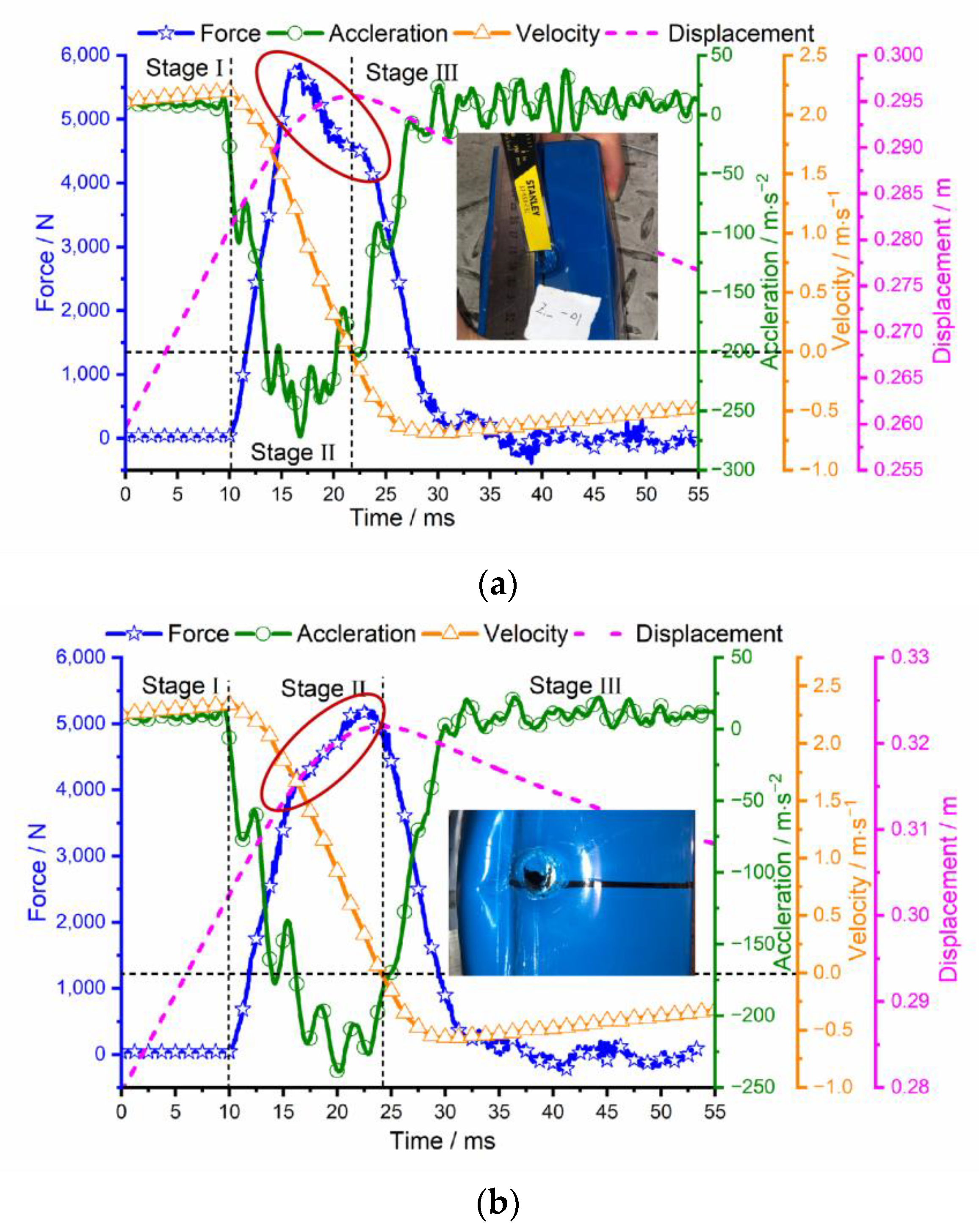
Figure 7 shows the Z− test results of the battery. It can be seen that the impact process with the conical indenter also experienced initial contact, extrusion deformation, and rebound stage. Because the impact process with the conical indenter was more likely to cause local compression and rupture of the battery, there were some differences between the conical indenter and the cylindrical indenter. As shown in the red circles in Figure 6, the force decreases slowly at the Z3− position and increases slowly at the Z4− position. Because the effect of the indenter is affected by both battery case and materials, the maximum deformation of the battery at the Z3− position occurs in the slow force drop process, while the maximum deformation of the battery at the Z4− position occurs in the quick force drop process. During the final state analysis of the battery, it can be seen that there was no rupture at the Z3− position, but the local area was depressed and both sides expanded. However, the battery was ruptured at the Z4− position and one side swelled, indicating that the indenter penetrated the cell. Under the same impact conditions, the deformation of the battery in the Z3− and Z4− positions was 14.4 mm and 19.4 mm, respectively. This demonstrates that battery deformation increases with proximity to the battery’s edge.
Figure 8 shows the voltage-temperature-time curves of the battery at both Z− positions. In the Z− positions tests, the shell structure, and positive and negative electrode materials were damaged, and there was no significant change in voltage, temperature, and insulation resistance during dynamic monitoring. However, some electrolyte leakage was observed after the tests. During the 48-h observation period, there was no combustion of the batteries. Although there was no abnormal phenomenon of voltage and temperature and no internal short-circuiting during the tests and 48-h observation period, the battery cases were broken, indicating that the battery was damaged.
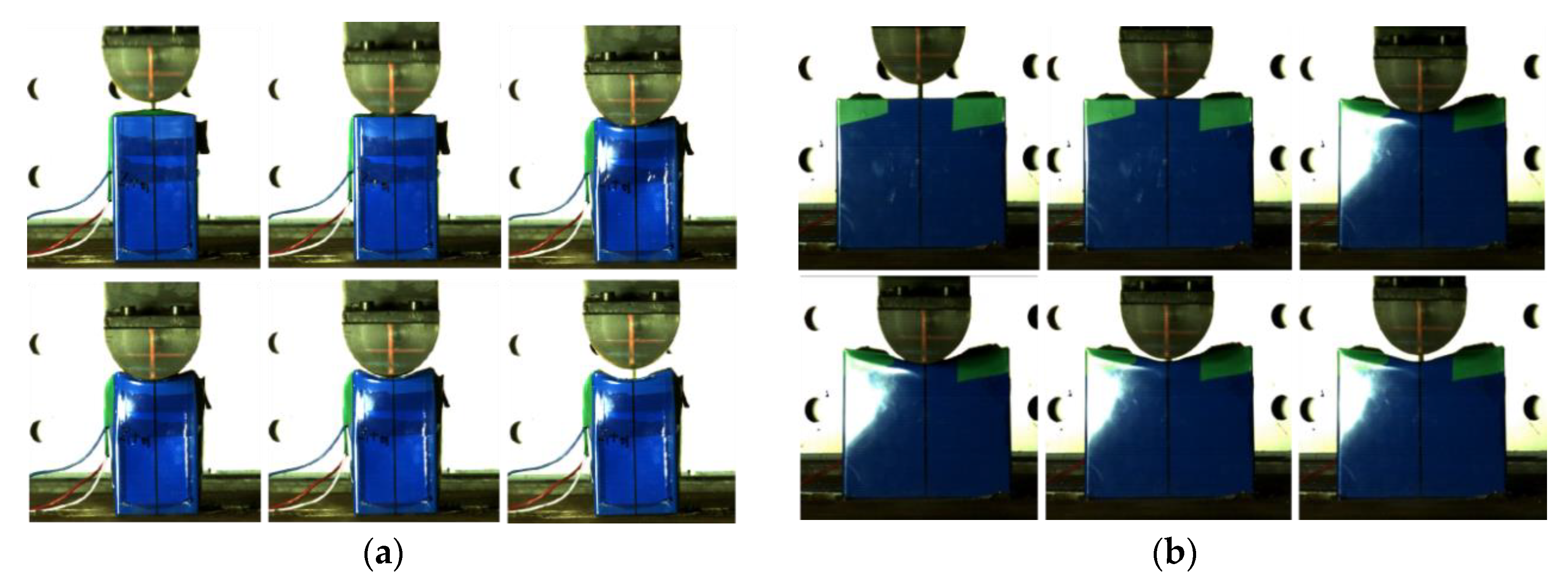
Figure 9 illustrates the dynamic impact process in the Z directions. In Figure 9a,b, it can be seen that the overall deformation of the upper half of the battery is more obvious during the impact process with the cylindrical indenter. In the Z1+ orientation, the battery showed a whole compression on one side of the tabs due to the large contact area between the battery and the indenter. In the Z2+ orientation, the contact area between the battery and the indenter was relatively small, and the battery was partially compressed in the middle of the battery on the tab side. We can conclude from this that the maximum pressure in the Z1+ orientation was much larger than that experienced in the Z2+ orientation under the same dynamic impact conditions.
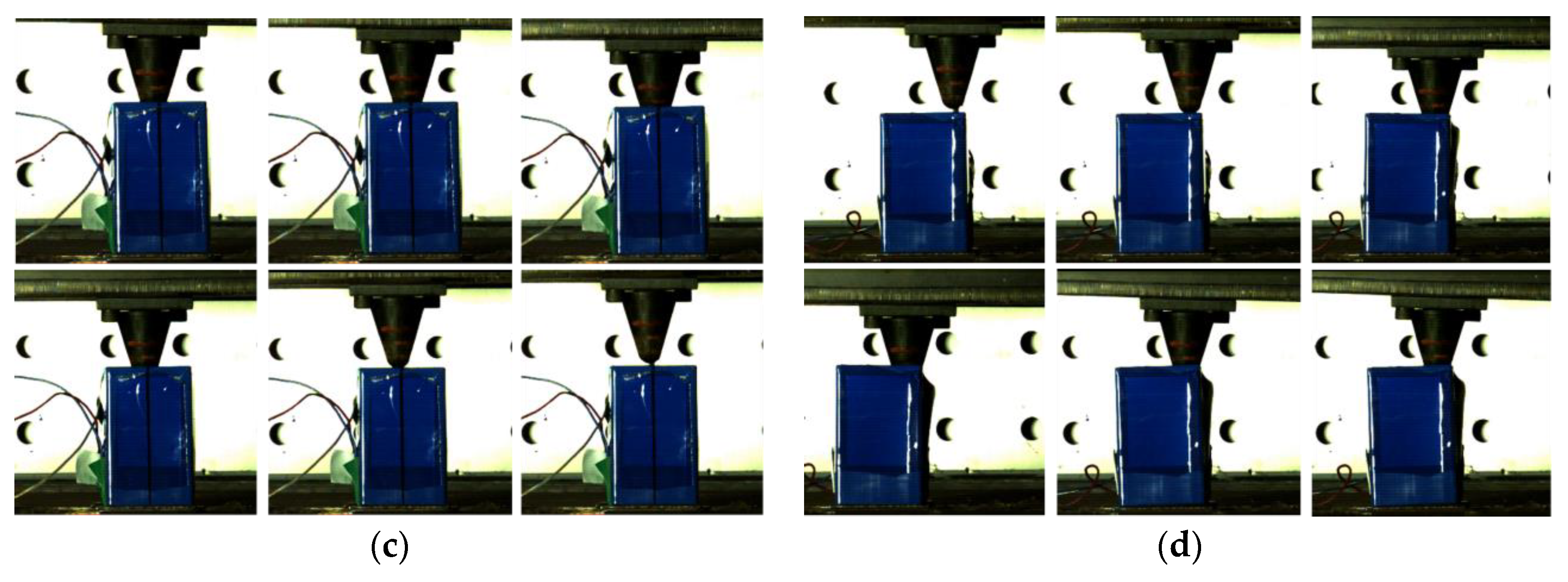
In Figure 9c,d, the battery shows a tendency toward local deformations in collisions with the conical indenter. Since the Z4− position is closer to the edge of the battery, the battery is more prone to deformation, collapse, and voids. As the case is composed of a ductile aluminum alloy and the negative and positive materials were also extruded, the battery case deformed but had no perforation at the Z3− position. Greater deformation at the Z4− position allowed the case to still be perforated.

3.2. Drop-Weight Impact Tests with Battery Modules

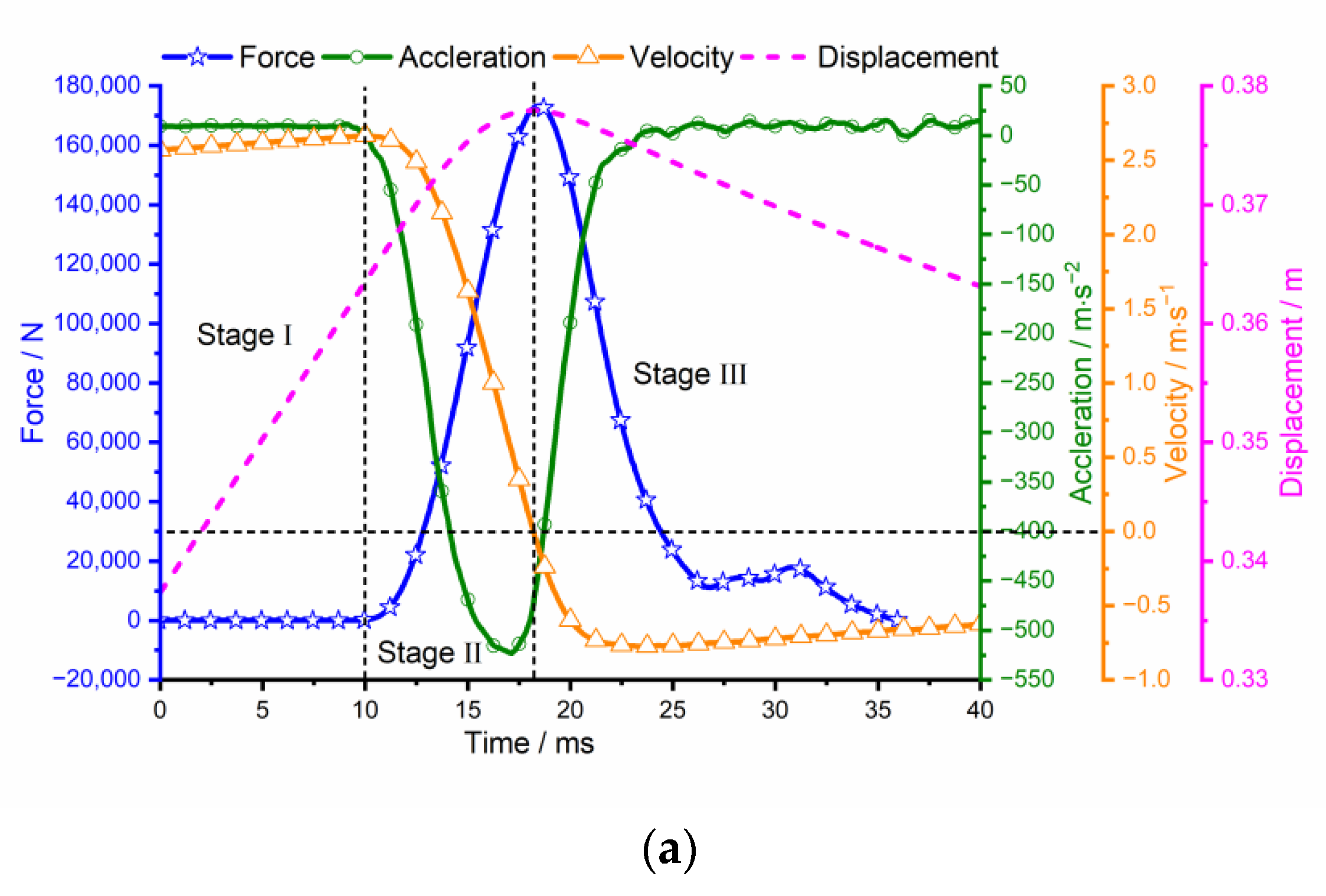
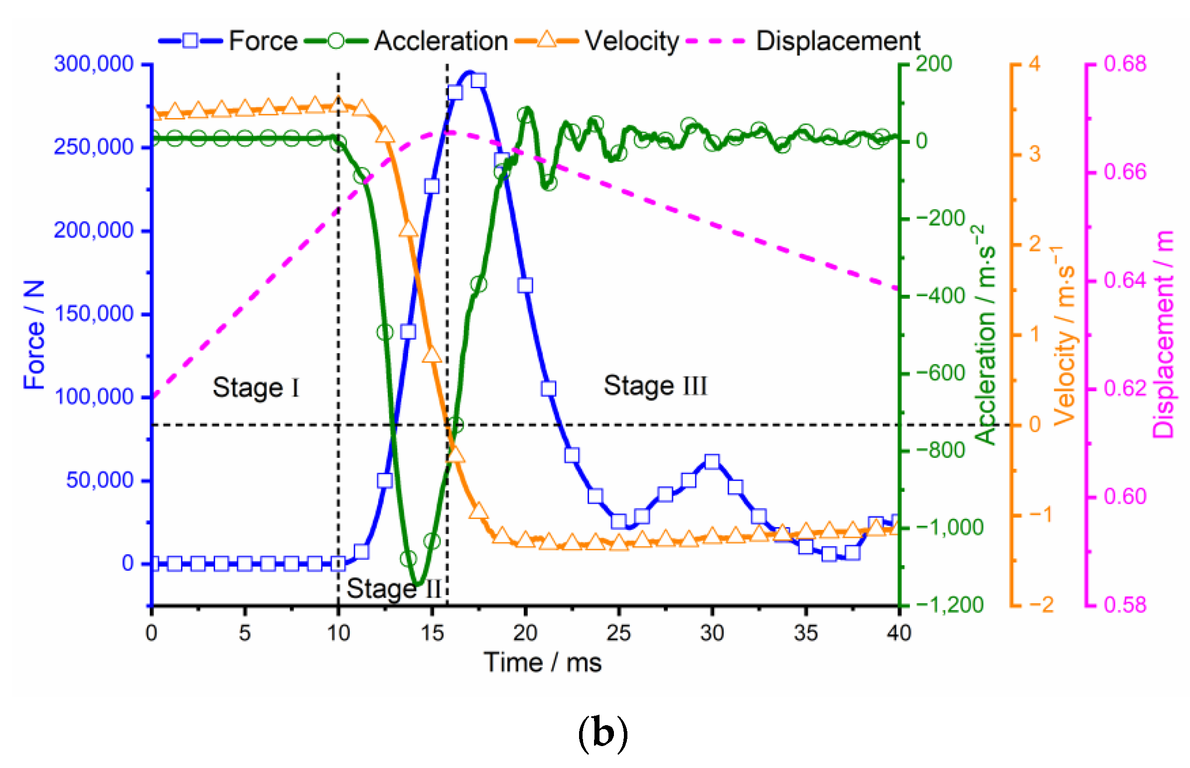
According to the test conditions in Table 1, the battery modules were tested. Figure 10 shows the experimental results from the Z1+ and Z2+ orientations. It can be seen that the dynamic impact process of the battery module is similar to the dynamic impact process of the cell, which is also divided into three stages: initial contact, extrusion deformation, and rebound. According to the displacement-time curve, the deformation of the battery module in the Z1+ and Z2+ orientations can be calculated as 14.4 mm and 11.4 mm, and the deformation percentages are 12.9% and 10.2%, respectively. For the Z1+ orientation, the indenter squeezed two cells, and the average impact energy of the cell in the battery module is 3.9 times that of the cell tested in the Z1+ orientation. However, the deformation of the battery module is comparable to the deformation of the cell. For the Z2+ orientation, the indenter squeezed four battery cells. The average impact energy of the cell in the battery module is 2.4 times that of the cell tested in the Z2+ orientation. The deformation observed in these cases is also comparable. The maximum impact forces for the Z1+ and Z2+ orientations were 173.2 kN and 295.3 kN, respectively. Due to the influence of the top cover plate, viscose glue, busbar, and the internal structure of the module, the maximum force that the module can withstand is much higher than that of the cell under the same deformation condition. Designs that distribute the force of a blunt impact along a module’s longer axis may therefore help reduce TR incidents in less severe vehicle collisions.
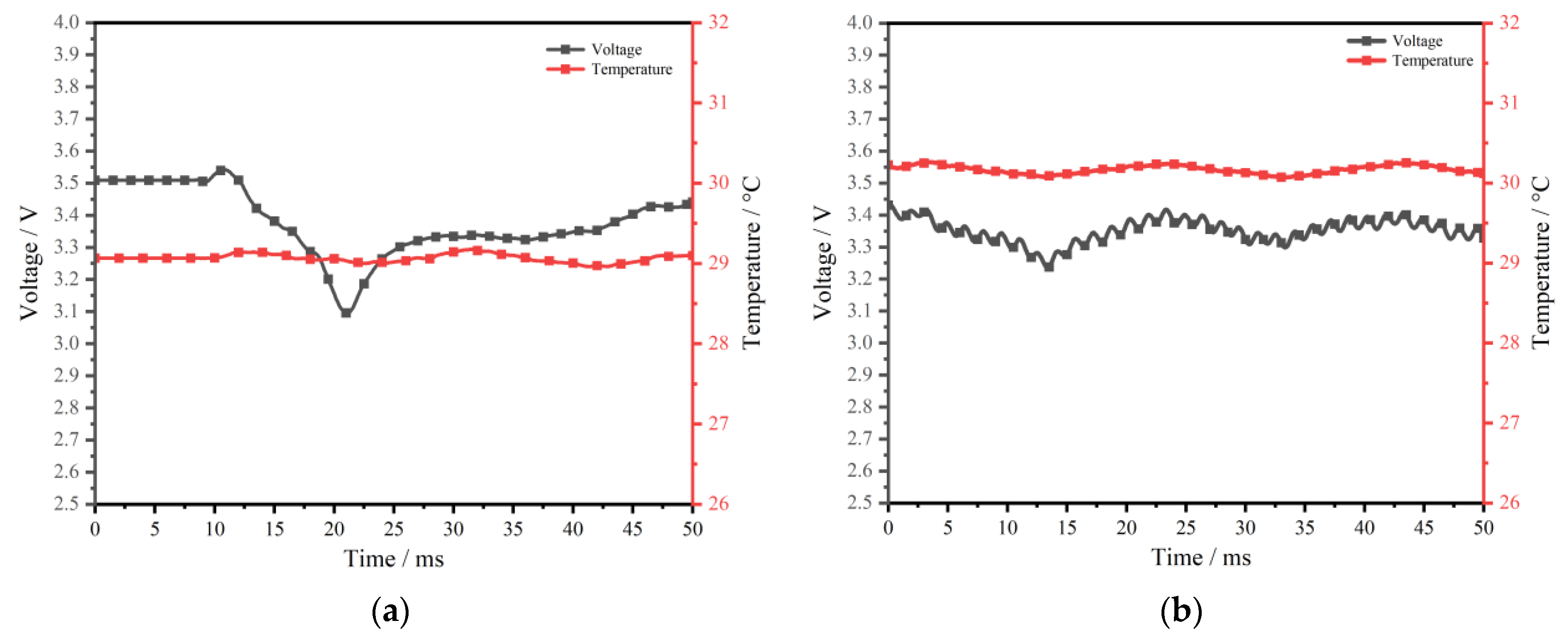
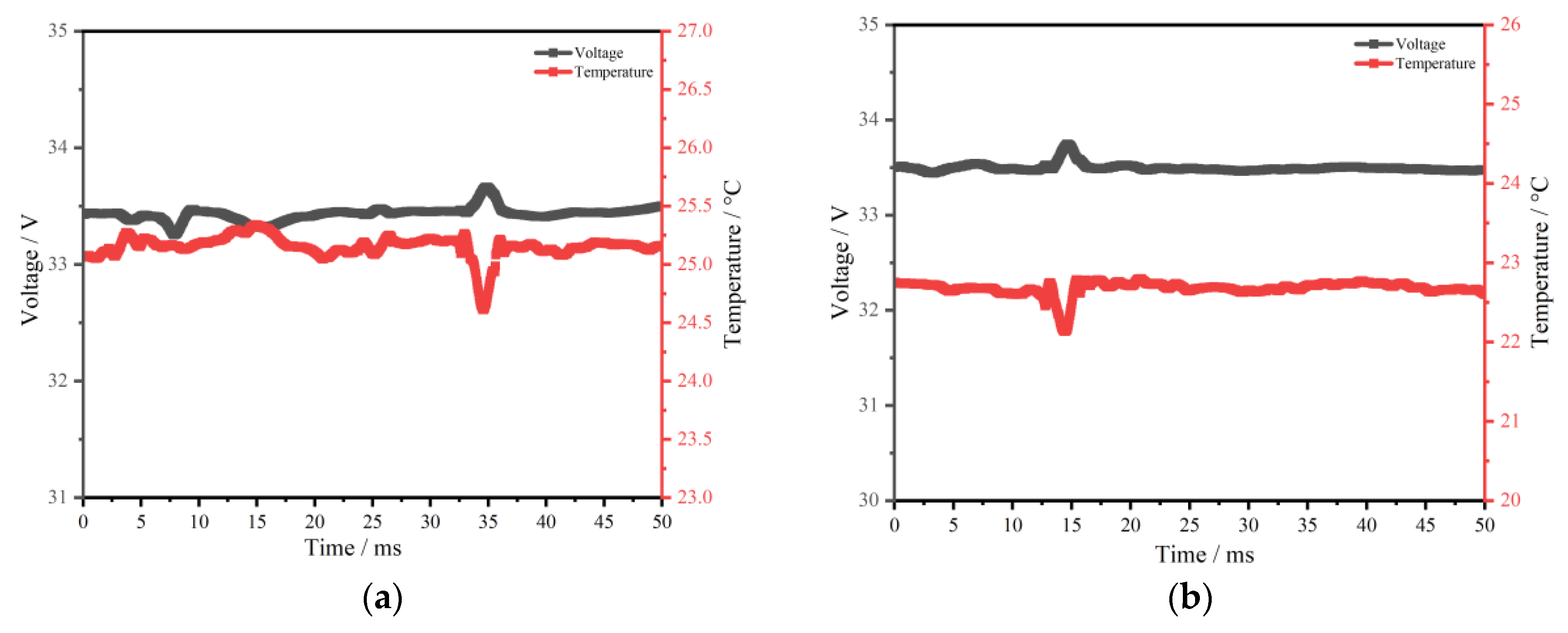
Figure 11 shows the voltage–temperature–time curve of the battery module after being impacted. By comparing Figure 11a,b, it can be seen that the voltage and temperature of the battery module jumped during both collisions. This can primarily be attributed to the deformation of the cell and the busbar in the module caused by the large extrusion area of the cylindrical impact head.
From the overall analysis, the voltage of the module returns to normal immediately after the jump, indicating that there is no obvious short circuit in the module during the dynamic monitoring process. At the later stage of the test, electrolyte leakage occurred in the module, but the voltage and temperature did not show any abnormalities, indicating that no short circuits occurred in the cell and the module. We can therefore interpret the small fluctuation in temperature readings as an artifact of the temperature sensor’s response to high-impact forces.
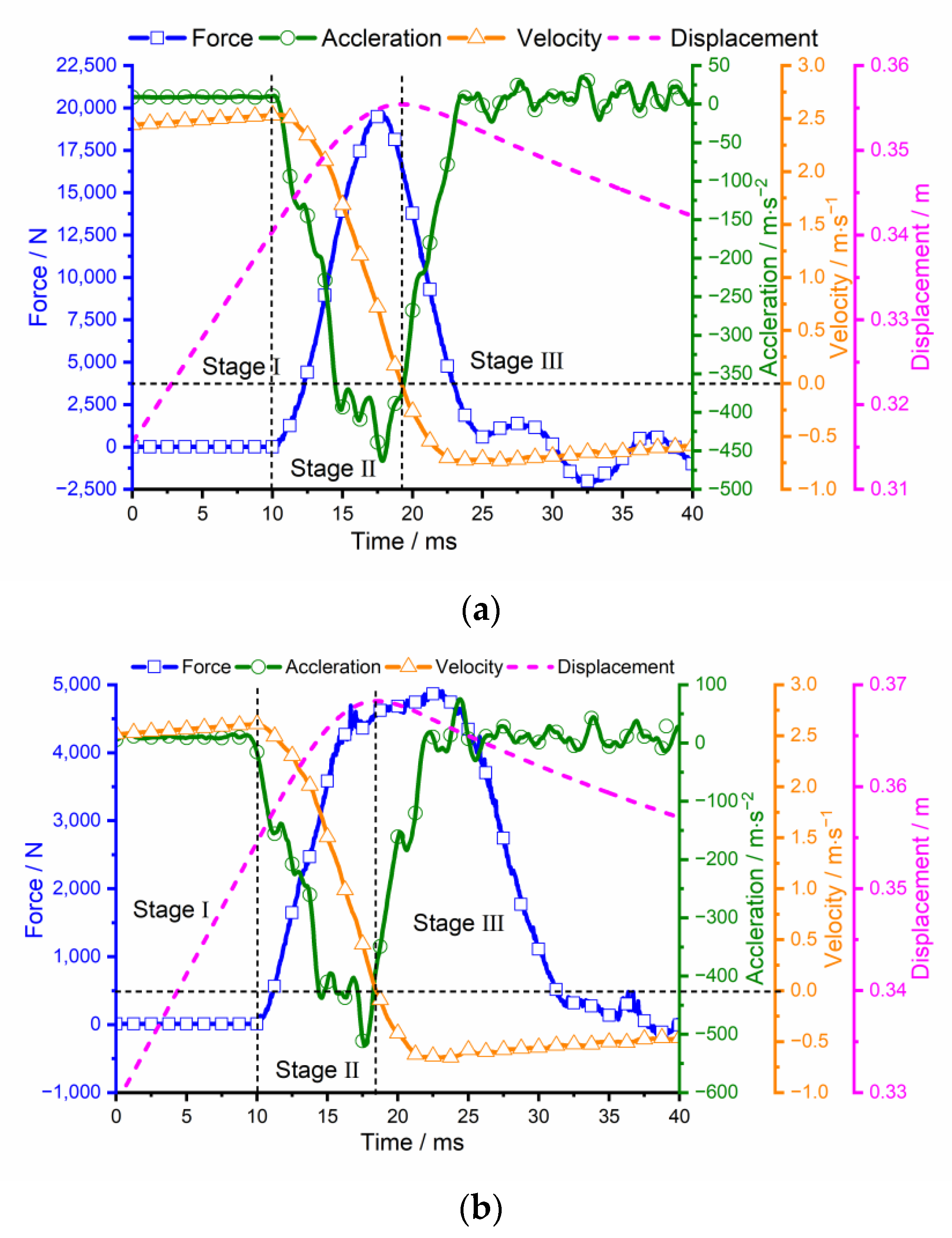
Figure 12 shows the test results of the battery module at the Z3− and Z4− positions. According to the displacement-time curve, the deformation of the battery module at the Z3− and Z4− positions are 15.1 mm and 14.1 mm, respectively, and the deformation rates are 13.5% and 12.6%, respectively. Similar to the extrusion results of the cells, the Z4− position of the battery module is more easily crushed. In the case of a 1 mm difference in deformation, the maximum forces by the battery module at the Z3− and Z4− positions were 19.7 kN and 4.9 kN.
Consistent with the description of experimental phenomena in both Z+ orientations, the module structure and cell were damaged in the Z− direction test, but there was no internal short circuit, and there was no significant change in voltage, temperature, and insulation resistance during dynamic monitoring, as shown in Figure 13. During the 48-h observation period, no combustion occurred in the battery module. Voltage, temperature, and insulation resistance showed no obvious changes. In the battery module or battery pack, when electrolyte leakage occurs in the battery cell, a capacity loss of the damaged battery cell in a short time may cause the battery module to perform inconsistently. Sufficient loss of electrolyte renders the battery nonfunctional. In addition, many common electrolytes are flammable. In proximity to exposed wiring and waste heat from the braking system, this can quickly result in a fire.
Figure 14 shows the deformation process of each tested form of extrusion. It can be seen that after the impact on the battery module, the external structure does not show obvious deformation. According to the later dismantling battery module, the cell that the intender did not contact was also squeezed, resulting in cell damage and electrolyte leakage. This shows that the damage caused by the impact of the battery cell in the battery module is relatively small, but the damage may extend beyond the apparent impact site. It can also be seen from Figure 14c,d that when the edge is subjected to the same impact energy, the intrusion of the conical impact head at the Z4− position is greater than that at the Z3− position.

3.3. Comparative Analysis of the Battery Cell and Module Test Results

Table 2 shows the statistical results of all tests. From the Z+ test results of the cell, it can be seen that the maximum impact pressure of the cell in the Z1+ orientation is about 2.25 times that measured in the Z2+ orientation, but the dynamic maximum intrusion difference is small. This indicates that the failure of the cell is closely related to the contact area of the impact position, and that the lateral load capacity of the cell is higher than that of the longitudinal direction. It can be seen from the Z− test results that at the same impact velocity, the intrusion of the cell at the Z4− position is about 1.35 times that at the Z3− position, indicating that the failure boundary of the cell is closely related to the position of the impact head. The closer to the edge of the battery cell, the easier it is to cause rupture damage to the cell. Compared with the test results of the cell, it can be seen that when the central position of the battery cell is squeezed, the deceleration of the impact head and the impact force of the cell are greater than that of the edge position, and the greater the impact speed, the greater the deceleration of the impact head; the greater the impact force, the stronger the load capacity of the central position. By comparing the test results of the battery module, it can be concluded that a greater impact velocity leads to a greater deceleration of the impact head and a greater impact force, which is similar to the conclusion of the cell tests. The maximum dynamic intrusion of the module is proportional to the maximum pressure and the impact energy per unit area. The load capacity per unit area varies at different locations. Through the observation of the later test, it can be found that when the deformation of the battery module is less than the deformation of the cell, internal electrolyte leakage occurs. This shows that the cell in the module is limited by displacement, which is more prone to shell rupture than the cell in the free state.
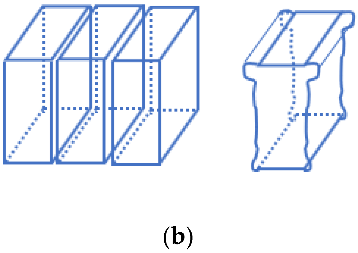
Figure 15 shows the deformation difference between the battery cell under a free state and a restricted state. It can be seen that in the free state, the cell expands to both sides, and the deformation is larger, so it is less prone to damage and electrolyte leakage. The extruded cell in the module is limited by the surrounding cell, showing a state of extrusion more prone to local stress concentration, which results in cell damage and electrolyte leakage.

4. Conclusions

Based on the bottom collision conditions that new energy vehicles may encounter during driving, the dynamic impact tests of cells and modules in the Z direction under 100% SOC were studied. Furthermore, the mechanical behavior, temperature changes, and voltage changes of the cell and module were analyzed, and the following conclusions were drawn.
(1) The impact process for the cell and module were roughly divided into initial contact, extrusion deformation, and rebound. Deformation and compaction, rupture of the external aluminum shell, and leakage of the electrolyte were observed. However, no internal short circuit or thermal runaway occurred during the tests.
(2) In typical cases of blunt force impact on the top side of the cell, the cell showed relatively uniform deformation. Under the same impact energy, the impact of the battery tab position reduced the intrusion of the cell. In typical point force impacts on the battery’s underside, the closer to the edge of the cell, the greater the chance of cell intrusion, with corresponding increases in electrolyte leakage.
(3) Under the same equivalent impact energy, the deformation of the cell was greater than that of the module. However, deformation of the module was more likely to result in electrolyte leakage than equivalent deformation of the free cell. The failure threshold of the module was lower than that of the cell.
From the results, it can be concluded that the damage tolerance of the cell could not be simply equivalent to the failure threshold of the module or even the battery pack in the protection design of the battery system. In addition, impact safety depended not only on the voltage change of the cell but also on the mechanical integrity of the battery, which will cause an external short circuit and/or electrolyte leakage.

Author Contributions

Methodology, J.S., C.Q. and Y.H.; Validation, J.S. and C.L.; Investigation, T.Y.; Writing—original draft, C.Q.; Writing—review & editing, J.S. and C.L. All authors have read and agreed to the published version of the manuscript.

Funding

This work was supported by the “Hazardous Assessment and Protection Methods of Combustion and Explosion Caused by thermal Runaway of Lithium-ion Batteries” project of the Chongqing Ministry of Education.

Institutional Review Board Statement

Not applicable.

Informed Consent Statement

Not applicable.

Data Availability Statement

Data available on request due to restrictions by confidentiality regulations of relevant corporations.

Conflicts of Interest

The authors declare that they have no known competing financial interests or personal relationships that could have appeared to influence the work reported in this paper.

References

  1. Zhu, X.; Wang, Z.; Wang, H.; Wang, C. Thermal runaway and safety management of lithium ion power battery. J. Mech. Eng. 2020, 56, 91–118. [Google Scholar]
  2. Zhang, C.; Zhao, S.; He, Y. An Integrated Method of the Future Capacity and RUL Prediction for Lithium-Ion Battery Pack. IEEE Trans. Veh. Technol. 2021, 71, 2601–2613. [Google Scholar] [CrossRef]
  3. Tran, M.K.; Mevawalla, A.; Aziz, A.; Panchal, S.; Xie, Y.; Fowler, M. A review of lithium-ion battery thermal runaway modeling and diagnosis approaches. Processes 2022, 10, 1192. [Google Scholar] [CrossRef]
  4. Zhao, S.; Zhang, C.; He, Y. Lithium-ion battery capacity and remaining useful life prediction using board learning system and long short-term memory neural network. J. Energy Storage 2022, 52, 104901. [Google Scholar] [CrossRef]
  5. Xu, H.; Fan, Y.; Zhang, Z.; Hu, R. Thermal runaway characteristics and mechanism of power battery under acupuncture and extrusion. Energy Storage Sci. Technol. 2020, 9, 1113–1126. [Google Scholar]
  6. Luo, H. Structural Failure Mechanism and Modeling of Lithium Ion Soft Pack Battery under Mechanical Abuse. Ph.D. Thesis, Tsinghua University, Beijing, China, 2018. [Google Scholar]
  7. Bao, Y.; Chen, H.; Fang, D. Mechanical analysis and design of flexible beads-and-thread lithium-ion battery. Extrem. Mech. Lett. 2020, 37, 100717. [Google Scholar] [CrossRef]
  8. Zhang, Y.; Ren, G.; Li, J. Safety design and protection based on high voltage electric vehicle collision. J. Automot. Saf. Energy Sav. 2017, 8, 388–396. [Google Scholar]
  9. Zhou, W.; Hao, F.; Fang, D. The effects of elastic stiffening on the evolution of the stress field within a spherical electrode particle of lithium-ion batteries. Int. J. Appl. Mech. 2013, 5, 1350040. [Google Scholar] [CrossRef]
  10. Zhou, W. Effects of external mechanical loading on stress generation during lithiation in Li-ion battery electrodes. Electrochim. Acta 2015, 185, 28–33. [Google Scholar] [CrossRef] [Green Version]
  11. Yang, W. Safety Analysis of Bottom Collision of Vehicle Power Battery Pack. Ph.D. Thesis, South China University of Technology, Guangzhou, China, 2019. [Google Scholar]
  12. Chen, Z.; Xiong, R.; Sun, F. Analysis and research status of battery safety accidents of electric vehicles. J. Mech. Eng. 2019, 55, 93–104. [Google Scholar]
  13. Liu, M. Study on Thermal Safety of Vehicle Power Battery under Extreme Abuse Conditions. Ph.D. Thesis, South China University of Technology, Guangzhou, China, 2018. [Google Scholar]
  14. Zhu, H.; Zhang, X.; Yang, J.; Zhang, B. Numerical study on shock wave characteristics of power battery for new energy vehicles. J. Automot. Saf. Energy Conserv. 2019, 10, 184–191. [Google Scholar]
  15. Liu, B.; Jia, Y.; Yuan, C.; Wang, L.; Gao, X.; Yin, S.; Xu, J. Safety Issues and Mechanisms of Lithium-ion Battery Cell Upon Mechanical Abusive Loading: A Review. Energy Storage Mater. 2020, 24, 85–112. [Google Scholar] [CrossRef]
  16. Luo, H.; Xia, Y.; Zhou, Q. Mechanical damage in a lithium-ion pouch cell under indentation loads. J. Power Sources 2017, 357, 61–70. [Google Scholar] [CrossRef]
  17. Xia, Y.; Chen, G.; Zhou, Q.; Shi, X.; Shi, F. Failure behaviours of 100% SOC lithium-ion battery modules under different impact loading conditions. Eng. Fail. Anal. 2017, 82, S1350630716306100. [Google Scholar] [CrossRef]
  18. Chen, X.; Yuan, Q.; Wang, T.; Ji, H.; Ji, Y.; Li, L.; Liu, Y. Experimental study on the dynamic behavior of prismatic lithium-ion battery upon repeated impact. Eng. Fail. Anal. 2020, 115, 104667. [Google Scholar] [CrossRef]
  19. Kalnaus, S.; Wang, H.; Watkins, T.R.; Simunovic, S.; Sengupta, A. Features of mechanical behavior of EV battery modules under high deformation rate. Extrem. Mech. Lett. 2019, 32, 100550. [Google Scholar] [CrossRef]
  20. Zhu, F.; Du, X.; Lei, J.; Audisio, L.; Sypeck, D. Experimental study on the crushing behaviour of lithium-ion battery modules. Int. J. Crashworthiness 2020, 26, 598–607. [Google Scholar] [CrossRef]
  21. Arora, S.; Shen, W.; Kapoor, A. Review of mechanical design and strategic placement technique of a robust battery pack for electric vehicles. Renew. Sustain. Energy Rev. 2016, 60, 1319–1331. [Google Scholar] [CrossRef]
  22. Zhu, J.; Zhang, X.; Wierzbicki, T.; Xia, Y.; Chen, G. Structural Designs for Electric Vehicle Battery Pack against Ground Impact. In Proceedings of the WCX World Congress Experience, Detroit, MI, USA, 10–12 April 2018. [Google Scholar] [CrossRef]
  23. Chen, Y.; Santhanagopalan, S.; Babu, V.; Ding, Y. Dynamic mechanical behavior of lithium-ion pouch cells subjected to high-velocity impact. Compos. Struct. 2019, 218, 50–59. [Google Scholar] [CrossRef]
  24. Kukreja, J.; Nguyen, T.; Siegmund, T.; Chen, W.; Tsutsui, W.; Balakrishnan, K.; Liao, H.; Parab, N. Crash analysis of a conceptual electric vehicle with a damage tolerant battery pack. Extrem. Mech. Lett. 2016, 9, 371–378. [Google Scholar] [CrossRef]
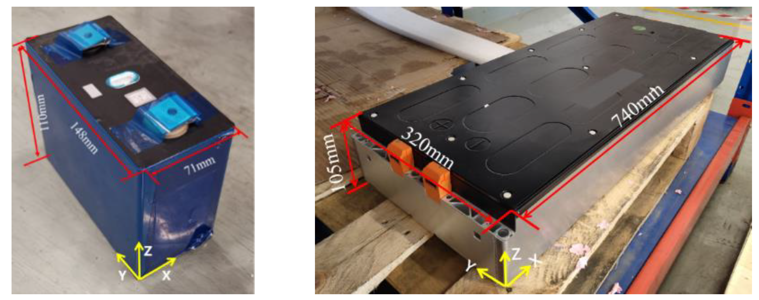
Figure 1. Battery cell and module.
Energies 15 09148 g001
Figure 2. The fixed mode diagram of the battery cell and module.
Energies 15 09148 g002
Figure 3. Impact position of the cell and module.
Energies 15 09148 g003
Figure 4. Schematic of the drop-weight test system.
Energies 15 09148 g004
Figure 5. Drop-weight test results of the battery along Z+ vectors. (a) Test results for Z1+ orientation; (b) Test results for Z2+ orientation.
Energies 15 09148 g005
Figure 6. Voltage–temperature–time curve of the battery in both Z+ orientations. (a) Test results for Z1+ orientation; (b) Test results for Z2+ orientation.
Energies 15 09148 g006
Figure 7. Drop-weight test results of the battery at Z− positions. (a) Test results at Z3− position; (b) Test results at Z4− position.
Energies 15 09148 g007
Figure 8. Voltage-temperature-time curve of the battery at Z− positions. (a) Test results at Z3− position; (b) Test results at Z4− position.
Energies 15 09148 g008
Figure 9. The dynamic impact process with different intenders. (a) Test process in the Z1+ orientation; (b) Test process in the Z2+ orientation; (c) Test process at the Z3− position; (d) Test process at the Z4− position.
Energies 15 09148 g009aEnergies 15 09148 g009b
Figure 10. Drop-weight test results of the battery module in Z+ orientations. (a) Test results of the battery module in the Z1+ orientation; (b) Test results of the battery module in the Z2+ orientation.
Energies 15 09148 g010aEnergies 15 09148 g010b
Figure 11. Voltage–temperature–time curve of the battery module in both Z+ orientations. (a) Z1+ orientation test results; (b) Z2+ orientation test results.
Energies 15 09148 g011
Figure 12. Drop-weight test results of the battery module at Z− directions. (a) Test results at Z3− position; (b) Test results at Z4− position.
Energies 15 09148 g012
Figure 13. Voltage-temperature-time curve of the battery at Z− positions. (a) Test results at Z3− position; (b) Test results at Z4− position.
Energies 15 09148 g013
Figure 14. Z direction extrusion deformation process of the battery module. (a) The Z1+ orientation test results of the module; (b) The Z2+ orientation test results of the module; (c) The Z3− position test results of the module; (d) The Z4− position test results of the module.
Energies 15 09148 g014
Figure 15. Comparison of the battery cell deformation modes. (a) Deformation mode of the cell in a free state; (b) Deformation mode of the cell under module constraint.
Energies 15 09148 g015aEnergies 15 09148 g015b
Table 1. Battery cell and Module Test Conditions.
PositionShape of IndenterMass of IndenterHeightTarget Intrusion
CellZ1+R40 cylinder40 kg40 cm11.4 mm
Z2+R40 cylinder40 kg20 cm11.4 mm
Z3−Conical25 kg27 cm11.4 mm
Z4−Conical25 kg27 cm11.4 mm
ModuleZ1+R40 cylinder200 kg32 cm11.4 mm
Z2+R40 cylinder200 kg62 cm11.4 mm
Z3−Conical25 kg32 cm11.4 mm
Z4−Conical25 kg32 cm11.4 mm
Table 2. Test results under different impact conditions.
SamplePositionShape of IndenterMass of Indenter/kgMaximum Speed/m·s−1Maximum Intrusion/mmMaximum Pressure/kNMaximum Acceleration/m·s−2Electrolyte Leakage
BatteryZ1+cylindrical402.8513.719.68619.6no
Z2+cylindrical402.0013.38.77275.6no
Z3−conical252.3314.45.8271.8no
Z4−conical252.3319.45.2238.3yes
ModuleZ1+cylindrical2002.5114.4173.2461.1yes
Z2+cylindrical2003.5111.4295.31142.8yes
Z3−conical252.6515.119.7522.9yes
Z4−conical252.6514.14.9519.1yes
Publisher’s Note: MDPI stays neutral with regard to jurisdictional claims in published maps and institutional affiliations.