

Formation of Yolk–Shell MoS2@void@Aluminosilica Microspheres with Enhanced Electrocatalytic Activity for Hydrogen Evolution Reaction


Abstract
1. Introduction
2. Materials and Methods
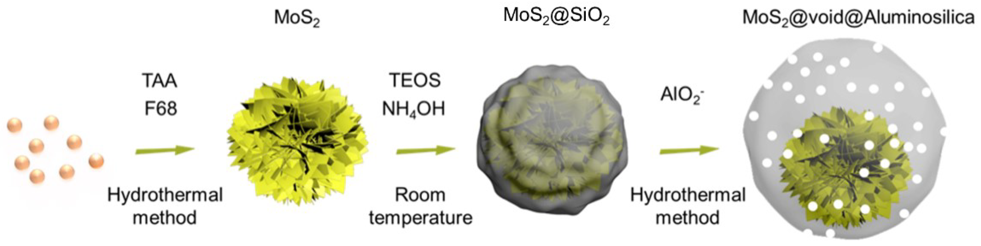
2.1. Preparation of Hierarchical MoS2 Microspheres Assembled by Nanosheets
2.2. Preparation of MoS2@SiO2 Microspheres
2.3. Preparation of MoS2@void@Aluminosilica Microspheres
2.4. Electrochemical Measurements
2.5. Characterization
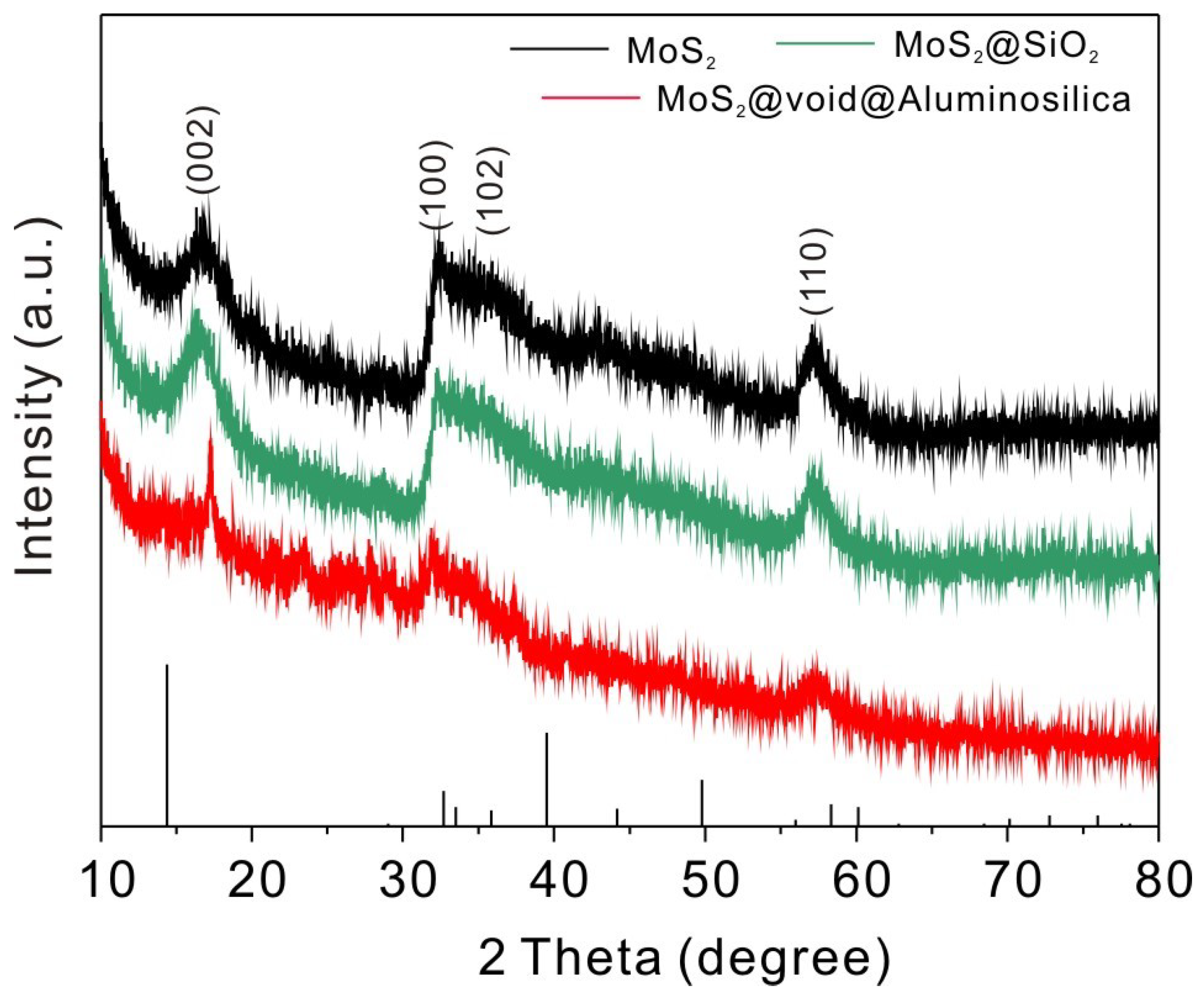
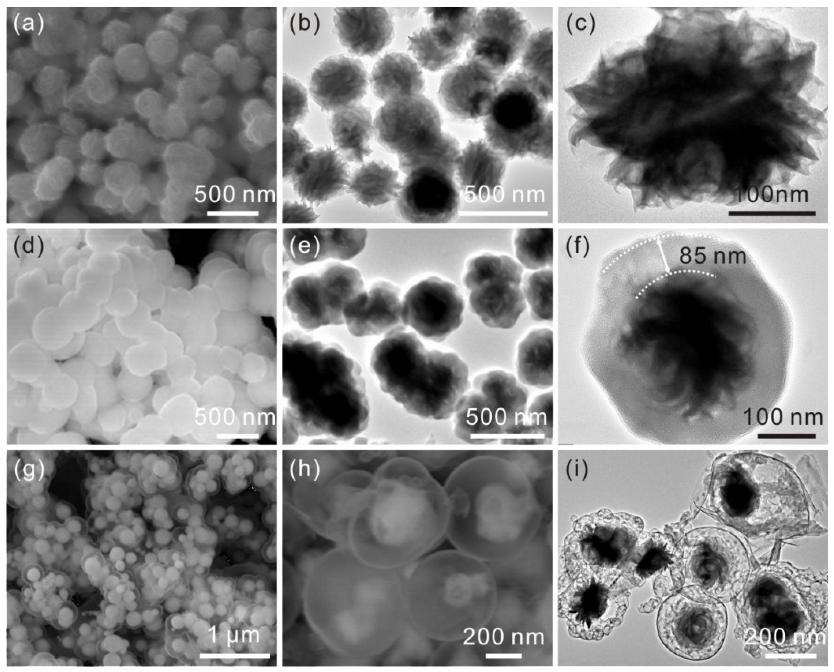
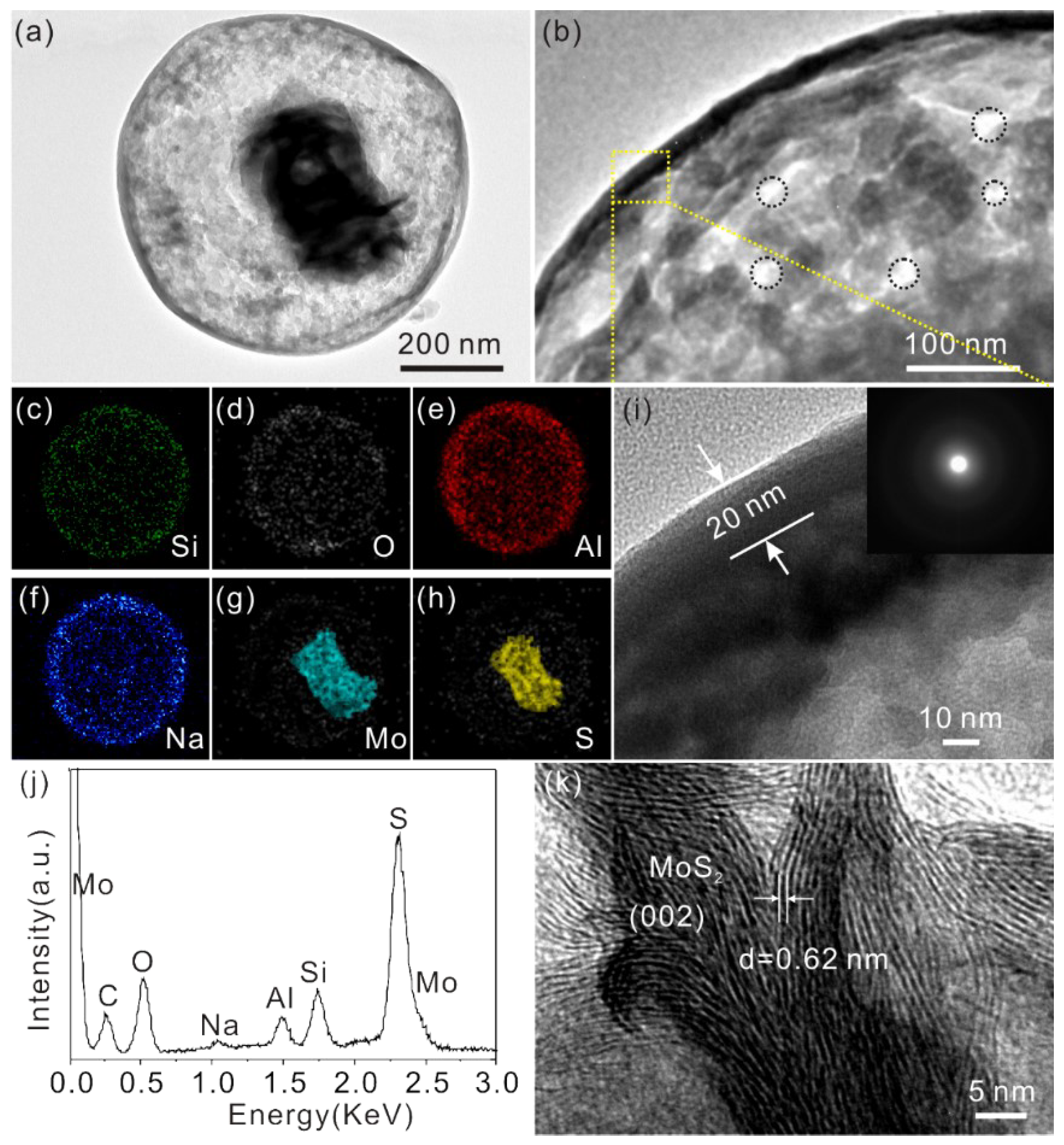
3. Results and Discussion
4. Conclusions
Supplementary Materials
Author Contributions
Funding
Conflicts of Interest
References
- Wu, Y.; Liu, X.; Han, D.; Song, X.; Shi, L.; Song, Y.; Niu, S.; Xie, Y.; Cai, J.; Wu, S.; et al. Electron density modulation of NiCo2S4 nanowires by nitrogen incorporation for highly efficient hydrogen evolution catalysis. Nat. Commun. 2018, 9, 1425. [Google Scholar] [CrossRef] [PubMed]
- Zhang, J.-Y.; Wang, H.; Tian, Y.; Yan, Y.; Xue, Q.; He, T.; Liu, H.; Wang, C.; Chen, Y.; Xia, B.Y. Anodic Hydrazine Oxidation Assists Energy-Efficient Hydrogen Evolution over a Bifunctional Cobalt Perselenide Nanosheet Electrode. Angew. Chem. Int. Ed. 2018, 57, 7649–7653. [Google Scholar] [CrossRef] [PubMed]
- Lu, S.; Hummel, M.; Gu, Z.; Wang, Y.; Wang, K.; Pathak, R.; Zhou, Y.; Jia, H.; Qi, X.; Zhao, X.; et al. Highly Efficient Urea Oxidation via Nesting Nano-Nickel Oxide in Eggshell Membrane-Derived Carbon. ACS Sustain. Chem. Eng. 2021, 9, 1703–1713. [Google Scholar] [CrossRef]
- Jia, H.; Lu, S.; Ra Shin, S.H.; Sushko, M.L.; Tao, X.; Hummel, M.; Thallapally, P.K.; Liu, J.; Gu, Z. In Situ anodic electrodeposition of two-dimensional conductive metal-organic framework@nickel foam for high-performance flexible supercapacitor. J. Power Sources 2022, 526, 231163. [Google Scholar] [CrossRef]
- Fang, L.; Wang, S.; Song, C.; Lu, S.; Yang, X.; Qi, X.; Liu, H. Boosting nitrate electroreduction to ammonia via in situ generated stacking faults in oxide-derived copper. Chem. Eng. J. 2022, 446, 137341. [Google Scholar] [CrossRef]
- Esposito, D.V.; Hunt, S.T.; Stottlemyer, A.L.; Dobson, K.D.; McCandless, B.E.; Birkmire, R.W.; Chen, J.G. Low-Cost Hydrogen-Evolution Catalysts Based on Monolayer Platinum on Tungsten Monocarbide Substrates. Angew. Chem. Int. Ed. 2010, 49, 9859–9862. [Google Scholar] [CrossRef] [PubMed]
- Xue, F.; Kang, S.; Dai, Y.; Li, T.; Shen, P.K.; Zhu, J.; Lu, S.; Fu, X.; Wang, L.; Feng, S.; et al. Hierarchical lead grid for highly stable oxygen evolution in acidic water at high temperature. J. Power Sources 2021, 493, 229635. [Google Scholar] [CrossRef]
- Liang, K.; Guo, L.; Marcus, K.; Zhang, S.; Yang, Z.; Perea, D.E.; Zhou, L.; Du, Y.; Yang, Y. Overall Water Splitting with Room-Temperature Synthesized NiFe Oxyfluoride Nanoporous Films. ACS Catal. 2017, 7, 8406–8412. [Google Scholar] [CrossRef]
- Lu, S.; Wang, Y.; Xiang, H.; Lei, H.; Xu, B.B.; Xing, L.; Yu, E.H.; Liu, T.X. Mass transfer effect to electrochemical reduction of CO2: Electrode, electrocatalyst and electrolyte. J. Energy Stor. 2022, 52, 104764. [Google Scholar] [CrossRef]
- Verma, J.; Goel, S. Cost-effective electrocatalysts for Hydrogen Evolution Reactions (HER): Challenges and Prospects. Int. J. Hydrog. Energy 2022, 47, 38964–38982. [Google Scholar] [CrossRef]
- Zhou, F.; Zhou, Y.; Liu, G.-G.; Wang, C.-T.; Wang, J. Recent advances in nanostructured electrocatalysts for hydrogen evolution reaction. Rare Met. 2021, 40, 3375–3405. [Google Scholar] [CrossRef]
- Wang, M.; Ju, P.; Li, W.; Zhao, Y.; Han, X. Ag2S nanoparticle-decorated MoS2 for enhanced electrocatalytic and photoelectrocatalytic activity in water splitting. Dalton Trans. 2017, 46, 483–490. [Google Scholar] [CrossRef] [PubMed]
- Yan, C.; Yang, X.; Lu, S.; Han, E.; Chen, G.; Zhang, Z.; Zhang, H.; He, Y. Hydrothermal synthesis of vanadium doped nickel sulfide nanoflower for high-performance supercapacitor. J. Alloys Compd. 2022, 928, 167189. [Google Scholar] [CrossRef]
- Zhang, Y.; Yu, W.; Zhai, X.; Liu, Z.; Su, L.; Teng, X.; Fu, G. The effect of oxygen pretreatment at hetero-interface on the photovoltaic properties of MoS2/Si heterojunction solar cells. J. Alloys Compd. 2019, 803, 1023–1031. [Google Scholar] [CrossRef]
- Zhu, C.; Zeng, Z.; Li, H.; Li, F.; Fan, C.; Zhang, H. Single-Layer MoS2-Based Nanoprobes for Homogeneous Detection of Biomolecules. J. Am. Chem. Soc. 2013, 135, 5998–6001. [Google Scholar] [CrossRef]
- Qiao, S.; Liu, J.; Fu, G.; Wang, S.; Ren, K.; Pan, C. Laser-induced photoresistance effect in Si-based vertical standing MoS2 nanoplate heterojunctions for self-powered high performance broadband photodetection. J. Mater. Chem. C 2019, 7, 10642–10651. [Google Scholar] [CrossRef]
- Hu, Z.; Liu, Q.; Chou, S.-L.; Dou, S.-X. Advances and Challenges in Metal Sulfides/Selenides for Next-Generation Rechargeable Sodium-Ion Batteries. Adv. Mater. 2017, 29, 1700606. [Google Scholar] [CrossRef]
- Kim, Y.; Jackson, D.H.K.; Lee, D.; Choi, M.; Kim, T.-W.; Jeong, S.-Y.; Chae, H.-J.; Kim, H.W.; Park, N.; Chang, H.; et al. In Situ Electrochemical Activation of Atomic Layer Deposition Coated MoS2 Basal Planes for Efficient Hydrogen Evolution Reaction. Adv. Funct. Mater. 2017, 27, 1701825. [Google Scholar] [CrossRef]
- Lu, X.; Lin, Y.; Dong, H.; Dai, W.; Chen, X.; Qu, X.; Zhang, X. One-Step Hydrothermal Fabrication of Three-dimensional MoS2 Nanoflower using Polypyrrole as Template for Efficient Hydrogen Evolution Reaction. Sci. Rep. 2017, 7, 42309. [Google Scholar] [CrossRef]
- Wang, H.; Lu, Z.; Kong, D.; Sun, J.; Hymel, T.M.; Cui, Y. Electrochemical Tuning of MoS2 Nanoparticles on Three-Dimensional Substrate for Efficient Hydrogen Evolution. ACS Nano 2014, 8, 4940–4947. [Google Scholar] [CrossRef]
- Najmaei, S.; Yuan, J.; Zhang, J.; Ajayan, P.; Lou, J. Synthesis and Defect Investigation of Two-Dimensional Molybdenum Disulfide Atomic Layers. Acc. Chem. Res. 2014, 48, 31–40. [Google Scholar] [CrossRef] [PubMed]
- Lu, H.; Chen, X.; Dai, W.; Zhang, K.; Liu, C.; Dong, H. Prickly Pear-Like Three-Dimensional Porous MoS2: Synthesis, Characterization and Advanced Hydrogen Evolution Reaction. Catalysts 2018, 8, 235. [Google Scholar] [CrossRef]
- Gao, M.-R.; Chan, M.K.Y.; Sun, Y. Edge-terminated molybdenum disulfide with a 9.4-Å interlayer spacing for electrochemical hydrogen production. Nat. Commun. 2015, 6, 7493. [Google Scholar] [CrossRef] [PubMed]
- Li, X.; Guo, S.; Li, W.; Ren, X.; Su, J.; Song, Q.; Sobrido, A.J.; Wei, B. Edge-rich MoS2 grown on edge-oriented three-dimensional graphene glass for high-performance hydrogen evolution. Nano Energy 2019, 57, 388–397. [Google Scholar] [CrossRef]
- Liu, J.; Yu, L.; Wu, C.; Wen, Y.; Yin, K.; Chiang, F.-K.; Hu, R.; Liu, J.; Sun, L.; Gu, L.; et al. New Nanoconfined Galvanic Replacement Synthesis of Hollow Sb@C Yolk–Shell Spheres Constituting a Stable Anode for High-Rate Li/Na-Ion Batteries. Nano Lett. 2017, 17, 2034–2042. [Google Scholar] [CrossRef]
- Wang, Y.; Kang, W.; Cao, D.; Fan, X.; Yang, H.; Yang, Z.; Sun, D. Yolk-shell ZnS@NC@MoS2 nanoboxes with enhanced sodium storage capability. Appl. Surf. Sci. 2022, 574, 151715. [Google Scholar] [CrossRef]
- Stöber, W.; Fink, A.; Bohn, E. Controlled Growth of Monodisperse Silica Spheres in the Micron Size Range. J. Colloid Interface Sci. 1968, 26, 62–69. [Google Scholar] [CrossRef]
- Li, X.-H.; Zhang, Y.-X.; Liu, Z.-L.; Liu, Q.-Z.; Li, B.; Zhu, G.-P.; Dai, K. A facile and novel approach for preparing monodispersed hollow aluminosilica microspheres with thin shell structures. RSC Adv. 2014, 4, 62209–62214. [Google Scholar] [CrossRef]
- Yang, L.-Z.; Zhu, Y.-J.; Tong, H.; Liang, Z.H.; Wang, W.-W. Hierarchical β-Ni(OH)2 and NiO Carnations Assembled from Nanosheet Building Blocks. Cryst. Growth Des. 2007, 7, 2716–2719. [Google Scholar] [CrossRef]
- Yang, L.; Cui, X.; Zhang, J.; Wang, K.; Shen, M.; Zeng, S.; Dayeh, S.A.; Feng, L.; Xiang, B. Lattice strain effects on the optical properties of MoS2 nanosheets. Sci. Rep. 2014, 4, 5649. [Google Scholar] [CrossRef]
- Wang, C.; Lin, H.; Liu, Z.; Wu, J.; Xu, Z.; Zhang, C. Controlled Formation of TiO2/MoS2 Core-Shell Heterostructures with Enhanced Visible-Light Photocatalytic Activities. Part. Part. Syst. Charact. 2016, 33, 221–227. [Google Scholar] [CrossRef]
- De Chialvo, M.R.G.; Chialvo, A.C. Hydrogen evolution reaction: Analysis of the Volmer-Heyrovsky-Tafel mechanism with a generalized adsorption model. J. Electroanal. Chem. 1994, 372, 209–223. [Google Scholar] [CrossRef]
- Hu, J.; Huang, B.; Zhang, C.; Wang, Z.; An, Y.; Zhou, D.; Lin, H.; Leung, M.K.H.; Yang, S. Engineering stepped edge surface structures of MoS2 sheet stacks to accelerate the hydrogen evolution reaction. Energy Environ. Sci. 2017, 10, 593–603. [Google Scholar] [CrossRef]
- Luo, Z.; Ge, J.; Liu, C.; Xing, W. Engineering the HER catalytic behavior of heteroatom-doped molybdenum disulfide via versatile partial cation exchange. J. Energy Chem. 2020, 41, 15–19. [Google Scholar] [CrossRef]
- Diao, L.; Zhang, B.; Sun, Q.; Wang, N.; Zhao, N.; Shi, C.; Liu, E.; He, C. An in-plane Co9S8@MoS2 heterostructure for the hydrogen evolution reaction in alkaline media. Nanoscale 2019, 11, 21479–21486. [Google Scholar] [CrossRef]
- Zhou, Q.; Zhao, G.; Rui, K.; Chen, Y.; Xu, X.; Dou, S.X.; Sun, W. Engineering additional edge sites on molybdenum dichalcogenides toward accelerated alkaline hydrogen evolution kinetics. Nanoscale 2019, 11, 717–724. [Google Scholar] [CrossRef]
- Meng, X.; Yu, L.; Ma, C.; Nan, B.; Si, R.; Tu, Y.; Deng, J.; Deng, D.; Bao, X. Three-dimensionally hierarchical MoS2/graphene architecture for high-performance hydrogen evolution reaction. Nano Energy 2019, 61, 611–616. [Google Scholar] [CrossRef]
- Chi, J.-Q.; Gao, W.-K.; Lin, J.-H.; Dong, B.; Yan, K.-L.; Qin, J.-F.; Liu, B.; Chai, Y.-M.; Liu, C.-G. N,P dual-doped hollow carbon spheres supported MoS2 hybrid electrocatalyst for enhanced hydrogen evolution reaction. Catal. Today 2019, 330, 259–267. [Google Scholar] [CrossRef]
- Zhang, J.; Wang, T.; Liu, P.; Liu, S.; Dong, R.; Zhuang, X.; Chen, M.; Feng, X. Engineering water dissociation sites in MoS2 nanosheets for accelerated electrocatalytic hydrogen production. Energy Environ. Sci. 2016, 9, 2789–2793. [Google Scholar] [CrossRef]
- Chen, P.; Zhou, T.; Wang, S.; Zhang, N.; Tong, Y.; Ju, H.; Chu, W.; Wu, C.; Xie, Y. Dynamic Migration of Surface Fluorine Anions on Cobalt-Based Materials to Achieve Enhanced Oxygen Evolution Catalysis. Angew. Chem. Int. Ed. 2018, 57, 15471–15475. [Google Scholar] [CrossRef]


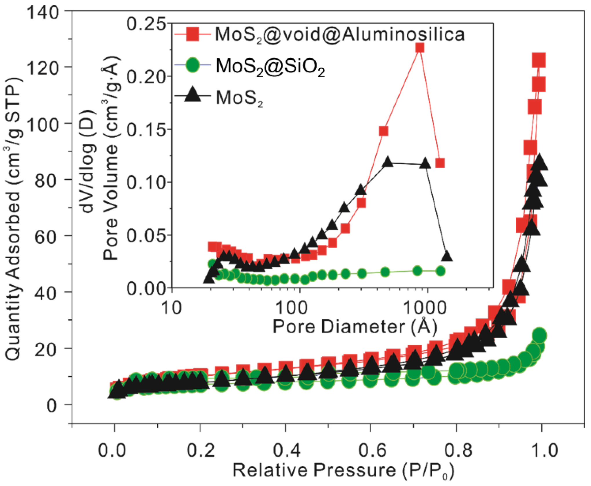
| Samples | BET (m2/g) | Average Pore Diameter (Å) | Pore Volume (cm3/g) |
|---|---|---|---|
| MoS2 | 27.35 | 140.5 | 0.096 |
| MoS2@SiO2 | 24.96 | 40.8 | 0.025 |
| MoS2@void@Aluminosilica | 36.49 | 110.0 | 0.100 |
| Catalyst | Synthesis Method | η10 (mV) * | Tafel Slope (mV dec−1) | Ref. |
|---|---|---|---|---|
| MoS2 (activated) | Commercial activated method | --- | 180 | [18] |
| 3D MoS2 nanoflowers | Hydrothermal method | 350 | 95.5 | [19] |
| se-MoS2 | Hydrothermal method | 104 | 59 | [33] |
| r-MoS2 | Microwave hydrothermal method | 217 | 121 | |
| MoS2 | Hydrothermal method | 340 | 105 | [34] |
| Zn-MoS2 | 290 | 110 | ||
| MoS2@3DC | Pyrolysis method | 252 | 102.8 | [35] |
| MoS2 | Hydrothermal method | 400 | 157 | [36] |
| 3D MoS2 | Hard template method | 270 | 112 | [37] |
| MoS2 | Template sacrificial method | 508 | 136 | [38] |
| MoS2 nanosheets | Hydrothermal method | 308 | 201 | [39] |
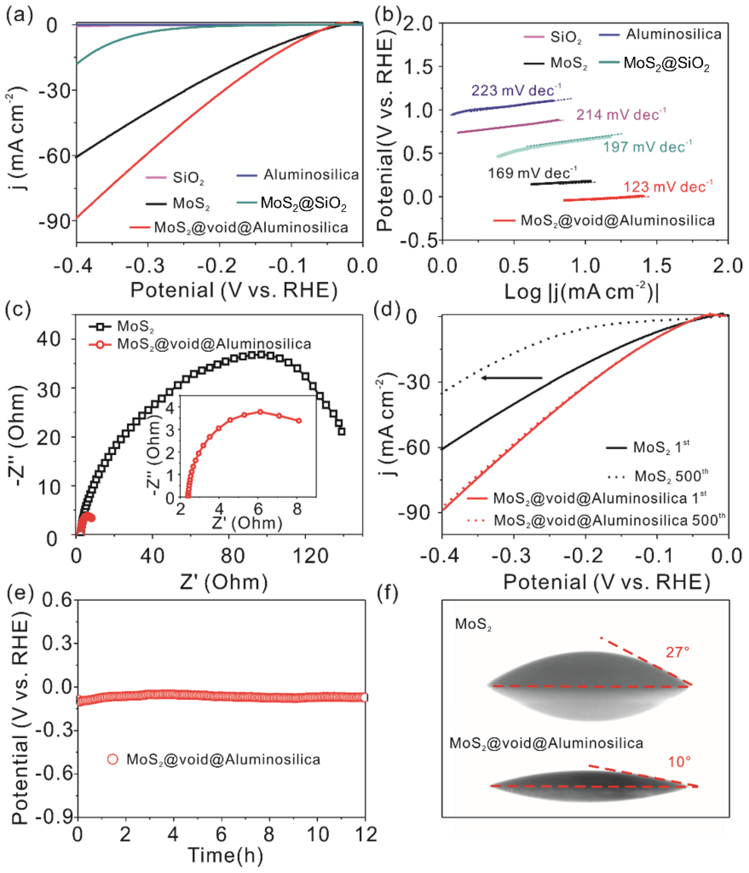
| MoS2 microspheres | Hydrothermal method | 127 | 169 | This work |
| MoS2@void@ Aluminosilica | Hydrothermal and hard template method | 104 | 123 |
Publisher’s Note: MDPI stays neutral with regard to jurisdictional claims in published maps and institutional affiliations. |
© 2022 by the authors. Licensee MDPI, Basel, Switzerland. This article is an open access article distributed under the terms and conditions of the Creative Commons Attribution (CC BY) license (https://creativecommons.org/licenses/by/4.0/).
Share and Cite
Li, L.; Zhao, Y.; Qiao, N.; Yu, Z.; Zhang, Y. Formation of Yolk–Shell MoS2@void@Aluminosilica Microspheres with Enhanced Electrocatalytic Activity for Hydrogen Evolution Reaction. Energies 2022, 15, 9031. https://doi.org/10.3390/en15239031
Li L, Zhao Y, Qiao N, Yu Z, Zhang Y. Formation of Yolk–Shell MoS2@void@Aluminosilica Microspheres with Enhanced Electrocatalytic Activity for Hydrogen Evolution Reaction. Energies. 2022; 15(23):9031. https://doi.org/10.3390/en15239031
Chicago/Turabian StyleLi, Li, Yuanyuan Zhao, Nanli Qiao, Zhengbao Yu, and Yongxing Zhang. 2022. "Formation of Yolk–Shell MoS2@void@Aluminosilica Microspheres with Enhanced Electrocatalytic Activity for Hydrogen Evolution Reaction" Energies 15, no. 23: 9031. https://doi.org/10.3390/en15239031
APA StyleLi, L., Zhao, Y., Qiao, N., Yu, Z., & Zhang, Y. (2022). Formation of Yolk–Shell MoS2@void@Aluminosilica Microspheres with Enhanced Electrocatalytic Activity for Hydrogen Evolution Reaction. Energies, 15(23), 9031. https://doi.org/10.3390/en15239031