
Wavelet Transform Processor Based Surface Acoustic Wave Devices


Abstract
1. Introduction
- The complicated conversion of the signal processing is eliminated, which may eliminate the signal distortion;
- Small size;
- Low cost;
- Good temperature stability;
- High reliability and reproducibility;
- Simple implementation techniques of the wavelet transform where the complication of its mathematical algorithms is eliminated.
- Provide a unified framework for WTP along with SAW devices by emphasizing their basic elements: the crystal types, design of inter-digital transducers IDT and frequency characteristics;
- Extend the understanding of the existing WTP algorithm by identifying their mathematical relationships with the SAW device interdigital transducers envelop function;
- Simulate the existing SAW devices in the literature concerning their accompanying problem;
- Investigate the trade-offs between different SAW elements;
- Pave the way for further enhancements by providing a wider perspective on WTP using a SAW device;
- Finally, determine the best parameter choices which provide the most side-lobe attenuation and least insertion loss with a neglected effect of a bulk acoustic wave.
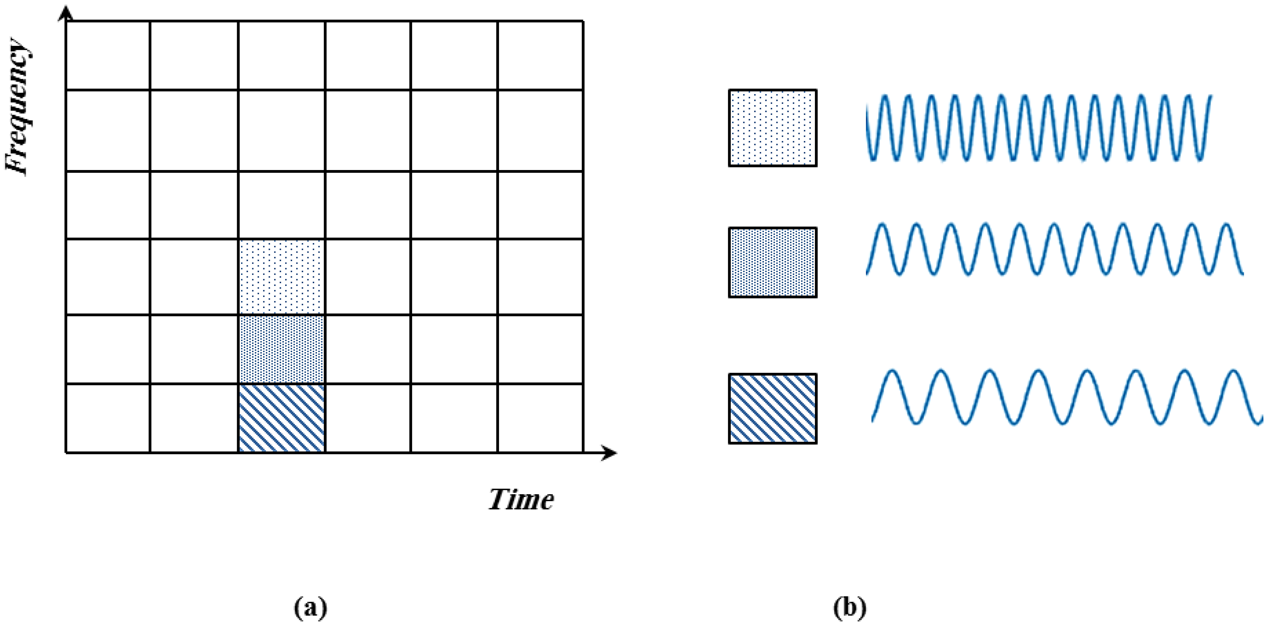
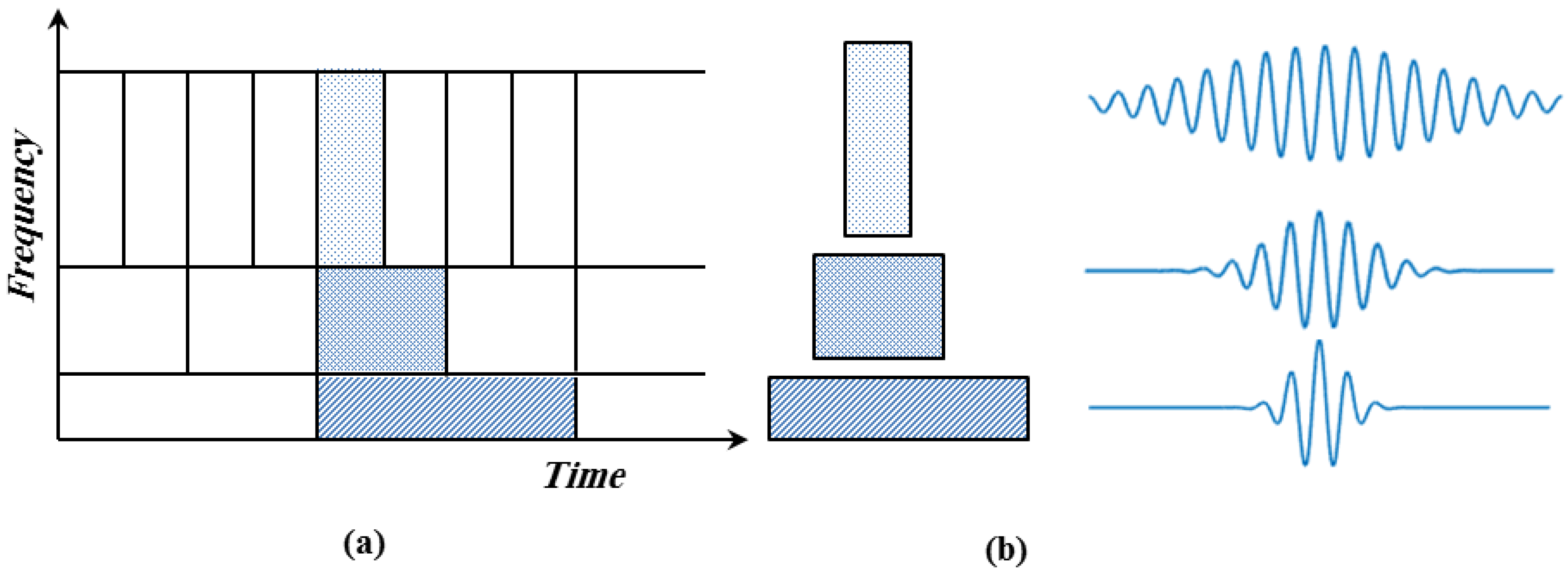
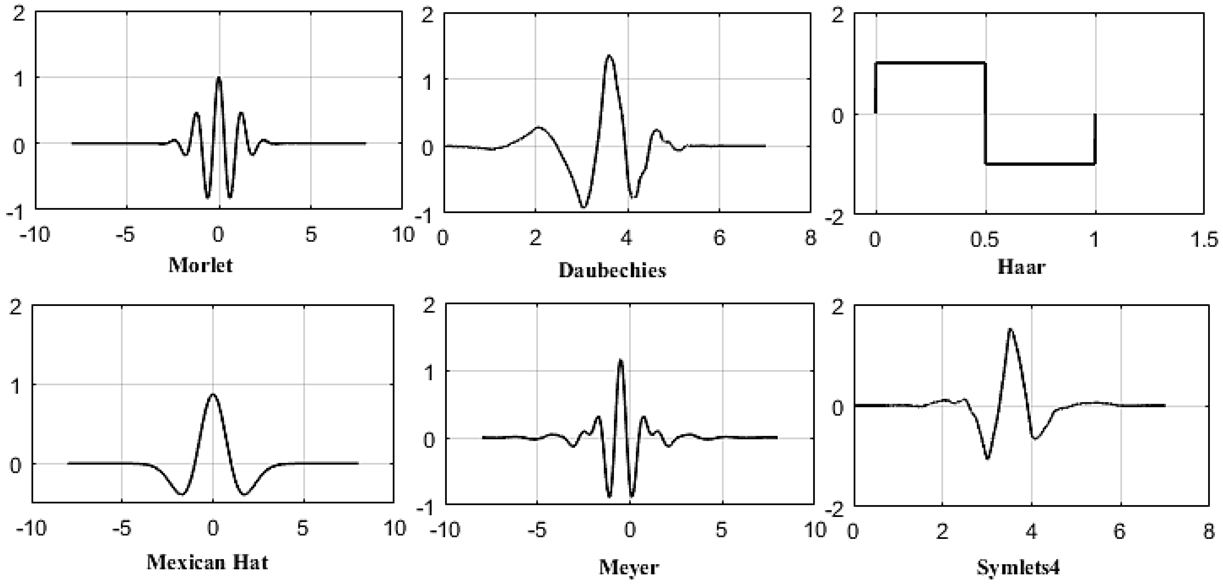
2. Wavelet Analysis
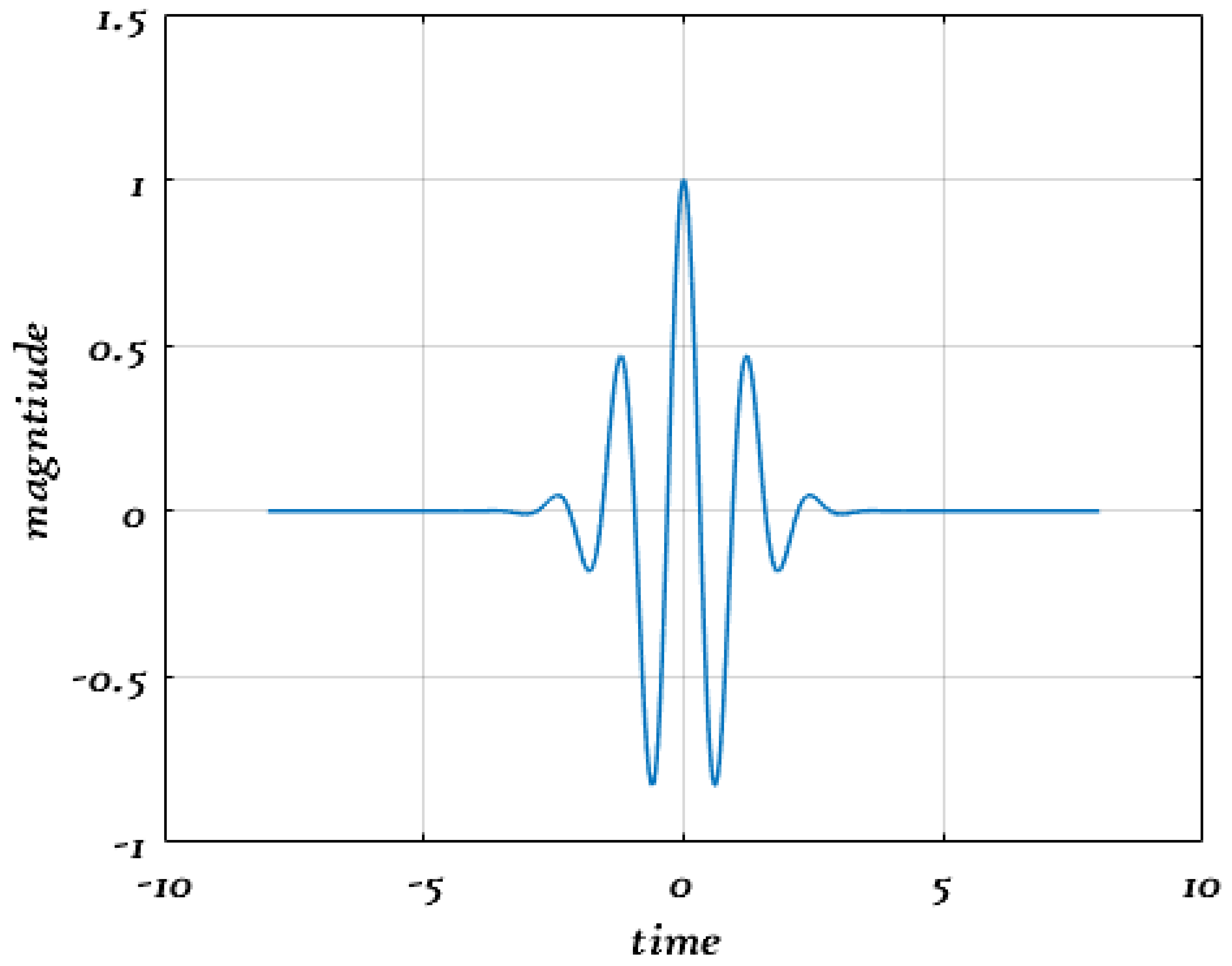
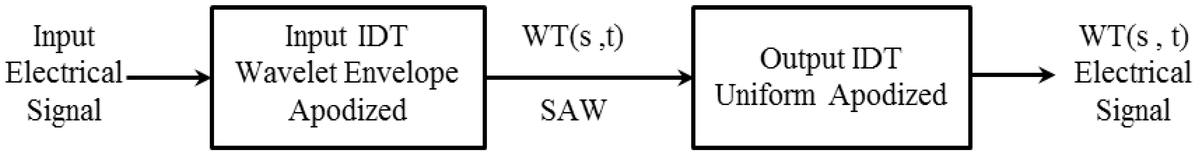
3. SAW Design-Based Morlet Wavelet Function
4. The Performance of WTP-Based SAW Device
4.1. ECC Value as a Function of Centre Frequency and Wavelet Scale
4.2. The Influence of ECC on IL
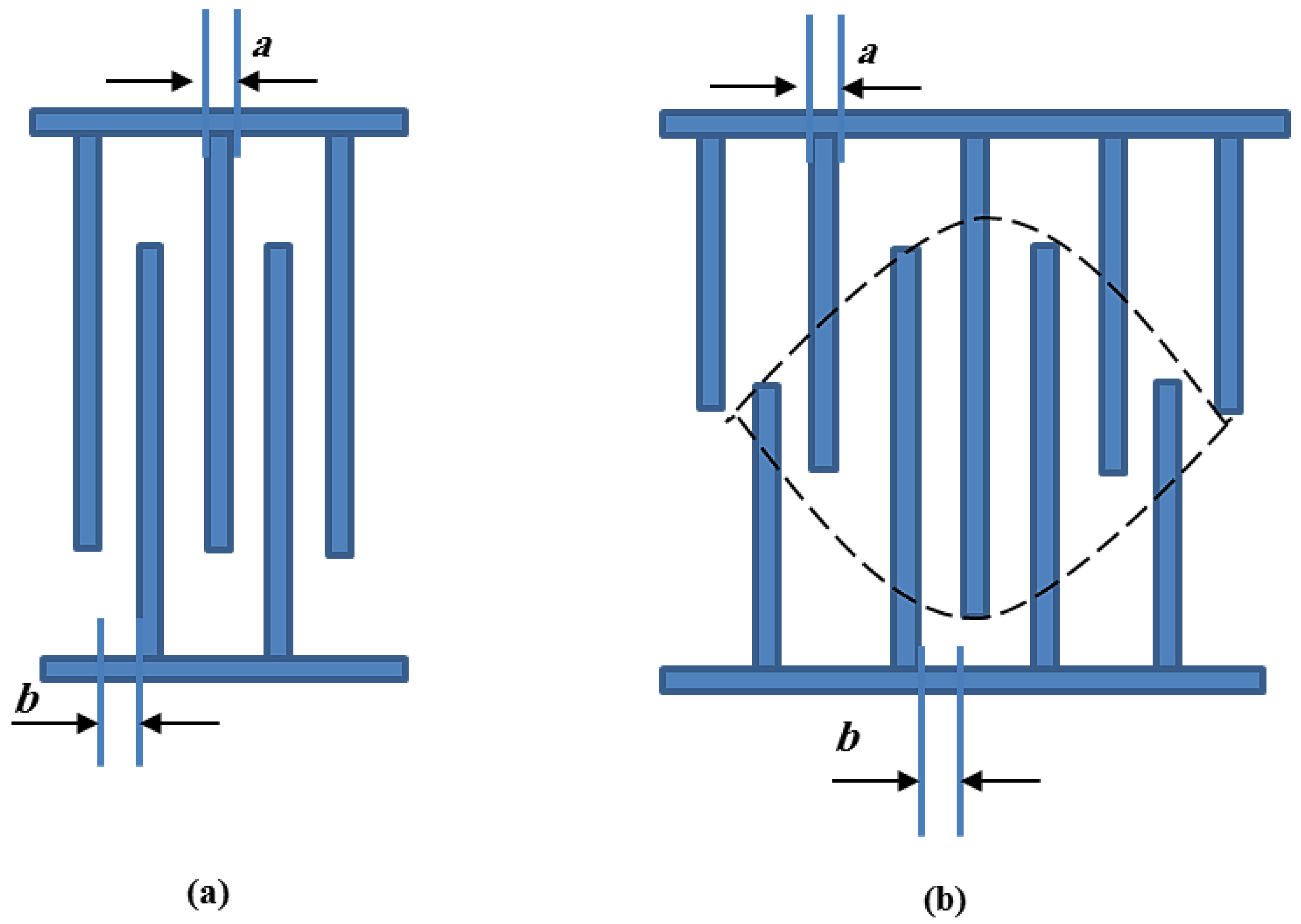
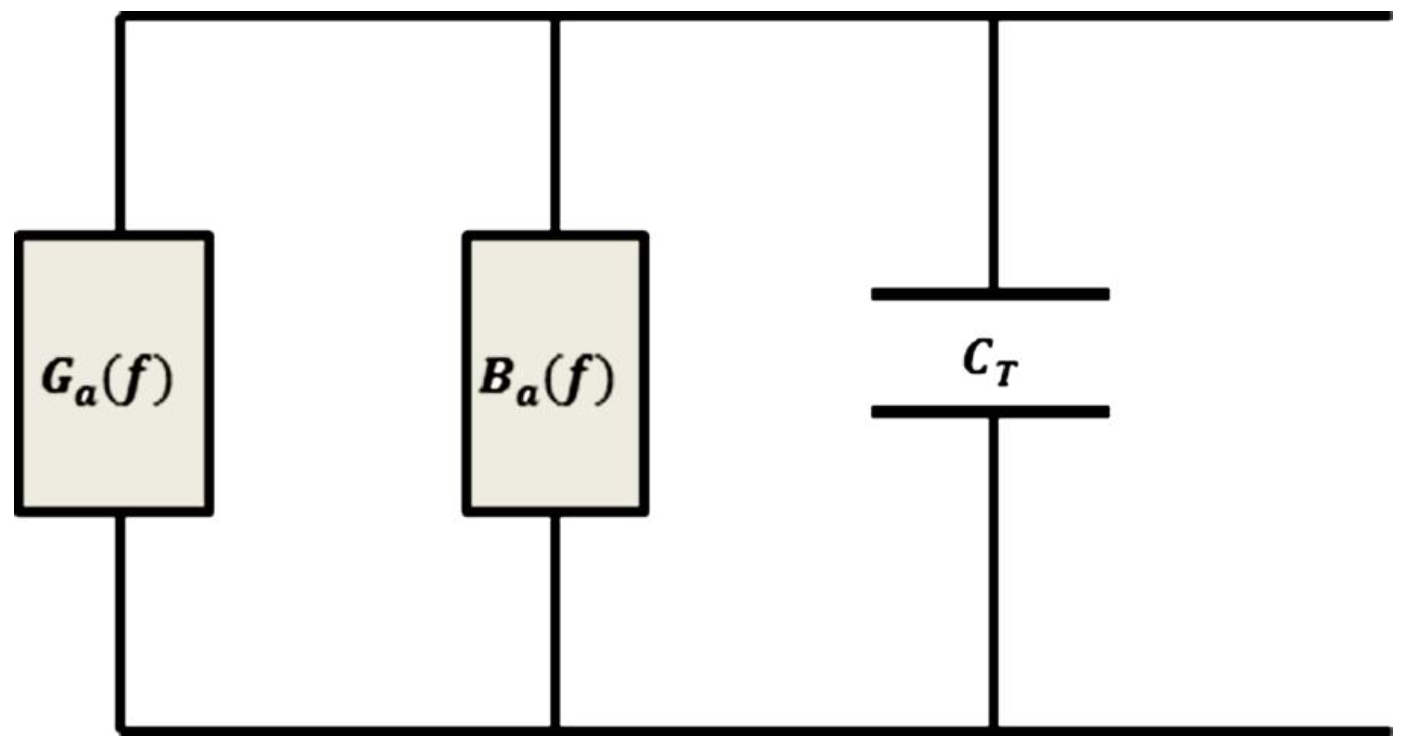
5. Interdigital Transducer Design
5.1. Specifications of the Input IDT Design
5.2. Specifications of the Output IDT Design
6. Accompanying Problems
6.1. The Bulk Acoustic Wave
6.2. The Sound Electricity Reclamation
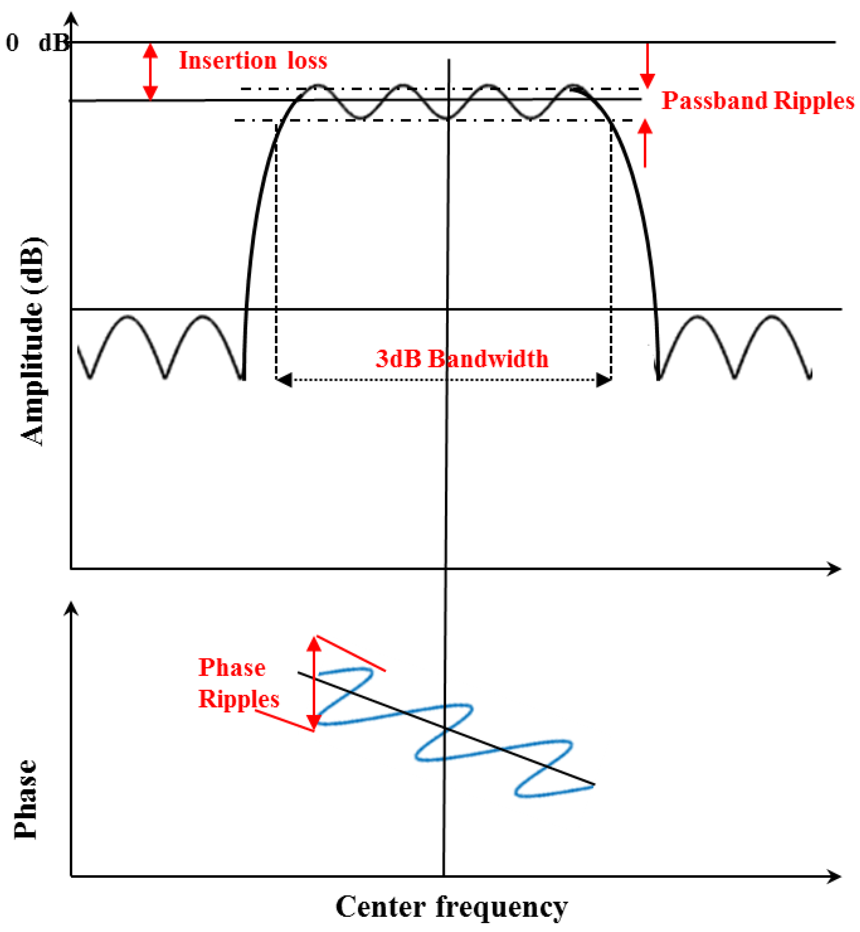
6.3. The Insertion Loss
6.4. The Selection of the Substrate Material
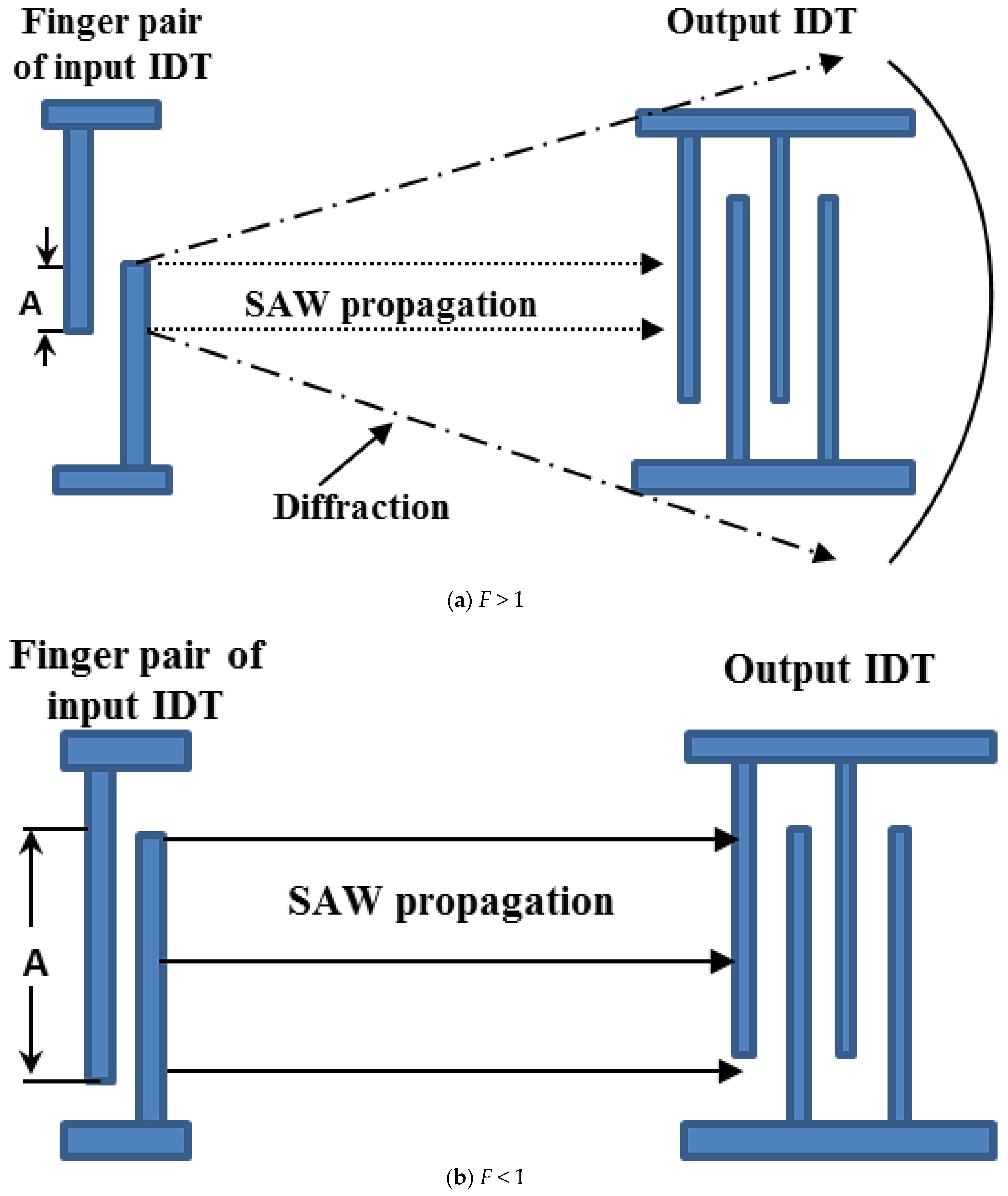
6.5. The Diffraction Problem from Input IDT to Output IDT
7. Results
8. Conclusions
Author Contributions
Funding
Data Availability Statement
Conflicts of Interest
Abbreviations
| WTP | Wavelet transform processor |
| VLSI | Very-large-scale integration |
| SAW | Surface acoustic wave |
| IDT | Interdigital transducer |
| CWT | Continues wavelet transform |
| DWT | Discrete wavelet transform |
| LSWA | Least-squares wavelet analysis |
| STFT | Short time Fourier transform |
| SER | The sound electricity reclamation |
| BAW | Bulk acoustic wave |
| IL | Insertion loss |
| ECC | Electromechanical coupling coefficient |
References
- Shi, B.; Cao, M.; Wang, Z.; Ostachowicz, W. A directional continuous wavelet transform of mode shape for line-type damage detection in plate-type structures. Mech. Syst. Signal Process 2022, 167, 108510. [Google Scholar] [CrossRef]
- Li, C.; Yu, Y.; Yang, Z.; Liu, Q.; Peng, X. ESR estimation for aluminum electrolytic capacitor of power electronic converter based on compressed sensing and wavelet transform. IEEE Trans. Ind. Electron. 2021, 69, 1948–1957. [Google Scholar] [CrossRef]
- Hong, H.P.; Cui, X.Z.; Qiao, D. Simulating nonstationary non-Gaussian vector process based on continuous wavelet transform. Mech. Syst. Signal Process 2022, 165, 108340. [Google Scholar] [CrossRef]
- Psaras, V.; Tzelepis, D.; Vozikis, D.; Adam, G.P.; Burt, G. Non-unit protection for HVDC grids: An analytical approach for wavelet transform-based schemes. IEEE Trans. Power Deliv. 2020, 36, 2634–2645. [Google Scholar] [CrossRef]
- Bilgili, F.; Lorente, D.B.; Kuşkaya, S.; Ünlü, F.; Gençoğlu, P.; Rosha, P. The role of hydropower energy in the level of CO2 emissions: An application of continuous wavelet transform. Renew. Energy 2021, 178, 283–294. [Google Scholar] [CrossRef]
- Li, X.X.; Li, D.; Ren, W.X.; Zhang, J.S. Loosening Identification of Multi-Bolt Connections Based on Wavelet Transform and ResNet-50 Convolutional Neural Network. Sensors 2022, 22, 6825. [Google Scholar] [CrossRef]
- Mahmood, M.R.; Matin, M.A.; Sarigiannidis, P.; Goudos, S.K. A Comprehensive Review on Artificial Intelligence/Machine Learning Algorithms for Empowering the Future IoT Toward 6G Era. IEEE Access 2022, 10, 87535–87562. [Google Scholar] [CrossRef]
- Parhi, K.K.; Nishitani, T. VLSI architectures for discrete wavelet transforms. IEEE Trans. Very Large Scale Integr. Syst. 1993, 1, 191–202. [Google Scholar] [CrossRef]
- Vishwanath, M.; Owens, R.M.; Irwin, M.J. VLSI architectures for the discrete wavelet transform. IEEE Trans. Circuits Syst. II Analog. Digit. Signal Process 1995, 42, 305–316. [Google Scholar] [CrossRef]
- Grzeszczak, A.; Mandal, M.K.; Panchanathan, S. VLSI implementation of discrete wavelet transform. IEEE Trans. Very Large Scale Integr. Syst. 1996, 4, 421–433. [Google Scholar] [CrossRef]
- Martina, M.; Masera, G. Low-complexity, efficient 9/7 wavelet filters VLSI implementation. IEEE Trans. Circuits Syst. II Express Briefs 2006, 53, 1289–1293. [Google Scholar] [CrossRef]
- Oweiss, K.G.; Mason, A.; Suhail, Y.; Kamboh, A.M.; Thomson, K.E. A scalable wavelet transform VLSI architecture for real-time signal processing in high-density intra-cortical implants. IEEE Trans. Circuits Syst. I Regul. Pap. 2007, 54, 1266–1278. [Google Scholar] [CrossRef]
- Wong, A.C.; Peng, G.D. Applications of Discrete Wavelet Transform in Optical Fibre Sensing. In Discrete Wavelet Transforms-Biomedical Application; IntechOpen: London, UK, 2011; pp. 221–248. [Google Scholar] [CrossRef]
- Cincotti, G.; Moreolo, M.S.; Neri, A. Optical wavelet signals processing and multiplexing. EURASIP J. Adv. Signal Process 2005, 2005, 742803. [Google Scholar] [CrossRef]
- Wen, C.; Zhu, C. Time synchronous dyadic wavelet processor array using surface acoustic wave devices. Smart Mater. Struct. 2006, 15, 939. [Google Scholar] [CrossRef]
- Lu, W.; Zhu, C.; Liu, Q.; Zhang, J. Implementing wavelet inverse-transform processor with surface acoustic wave device. Ultrasonics 2013, 53, 447–454. [Google Scholar] [CrossRef] [PubMed]
- Mazalan, M.B.; Noor, A.M.; Wahab, Y.; Yahud, S.; Zaman, W.S.W.K. Current Development in Interdigital Transducer (IDT) Surface Acoustic Wave Devices for Live Cell In Vitro Studies: A Review. Micromachines 2021, 13, 30. [Google Scholar] [CrossRef]
- Samarentsis, A.G.; Pantazis, A.K.; Tsortos, A.; Friedt, J.M.; Gizeli, E. Hybrid sensor device for simultaneous surface plasmon resonance and surface acoustic wave measurements. Sensors 2020, 20, 6177. [Google Scholar] [CrossRef]
- Liu, S.; Lu, W.; Feng, Y. Research on three key problems of the design of the wavelet transform processor using surface acoustic wave devices. IET Circuits Devices Syst. 2017, 11, 1–6. [Google Scholar]
- Lu, W.; Zhu, C.; Liu, J.; Liu, Q. Implementing wavelet transform with SAW elements. Sci. China Ser. E Technol. Sci. 2003, 46, 627–638. [Google Scholar] [CrossRef]
- Ghaderpour, E.; Pagiatakis, S.D.; Hassan, Q.K. A survey on change detection and time series analysis with applications. Appl. Sci. 2021, 11, 6141. [Google Scholar] [CrossRef]
- Galli, A.W.; Heydt, G.T.; Ribeiro, P.F. Exploring the power of wavelet analysis. IEEE Comput. Appl. Power 1996, 9, 37–41. [Google Scholar] [CrossRef]
- Graps, A. An introduction to wavelets. IEEE Comput. Sci. Eng. 1995, 2, 50–61. [Google Scholar] [CrossRef]
- Vetterli, M.; Herley, C. Wavelets and filter banks: Theory and design. IEEE Trans. Signal Process 1992, 40, 2207–2232. [Google Scholar] [CrossRef]
- Ghaderpour, E. Least-squares wavelet and cross-wavelet analyses of VLBI baseline length and temperature time series: Fortaleza–Hartebeesthoek–Westford–Wettzell. Publ. Astron. Soc. Pac. 2021, 133, 014502. [Google Scholar] [CrossRef]
- Ghaderpour, E.; Pagiatakis, S.D. LSWAVE: A MATLAB software for the least-squares wavelet and cross-wavelet analyses. GPS Solut. 2019, 23, 50. [Google Scholar] [CrossRef]
- Saeed, E.A.; Abdulhassan, K.M.; Al-Atbee, O.Y. Series and Parallel Arc Fault Detection in Electrical Buildings Based on Discrete Wavelet Theory. Iraqi J. Electr. Electron. Eng. 2021, 17, 94–101. [Google Scholar] [CrossRef]
- Lu, W.; Gao, L.; Liu, Q.; Zhang, J.; Zhang, H. Electrode-width-weighted wavelet transform processor using SAW devices. Microelectron. Int. 2017, 34, 75–83. [Google Scholar] [CrossRef]
- Wen, C.; Zhu, C.; Ju, Y.; Qiu, Y.; Xu, H.; Lu, W. Optimal frequency band design scheme of dyadic wavelet processor array using surface acoustic wave devices. IEEE Trans. Ind. Electron. 2008, 56, 949–955. [Google Scholar] [CrossRef]
- Russell, B.; Han, J. Jean Morlet and the continuous wavelet transform. CREWES Res. Rep. 2016, 28, 115. [Google Scholar]
- Lee, D.T.; Yamamoto, A. Wavelet analysis: Theory and applications. Hewlett Packard J. 1994, 45, 44. [Google Scholar] [CrossRef]
- Büssow, R. An algorithm for the continuous Morlet wavelet transform. Mech. Syst. Signal Process 2007, 21, 2970–2979. [Google Scholar] [CrossRef]
- Campbell, C. Surface Acoustic Wave Devices and Their Signal Processing Applications; Elsevier: Amsterdam, The Netherlands, 2012. [Google Scholar] [CrossRef]
- Xu, H.; Jin, H.; Dong, S.; Song, X.; Chen, J.; Xuan, W.; Luo, J. Mode analysis of Pt/LGS surface acoustic wave devices. Sensors 2020, 20, 7111. [Google Scholar] [CrossRef]
- Govindarajan, R.; Rojas-Nastrucci, E.; Kim, D. Surface Acoustic Wave-Based Flexible Piezocomposite Strain Sensor. Crystals 2021, 11, 1576. [Google Scholar] [CrossRef]
- Liu, S.; Lu, W.; Zhu, C. Research on two-port network of wavelet transform processor using surface acoustic wavelet devices and its application. Ultrasonics 2017, 81, 81–85. [Google Scholar] [CrossRef] [PubMed]
- Lu, W.; Zhu, C.; Kuang, L.; Zhang, T.; Zhang, J. Solution to the influence of the MSSW propagating velocity on the bandwidths of the single-scale wavelet-transform processor using MSSW device. Ultrasonics 2012, 52, 145–150. [Google Scholar] [CrossRef] [PubMed]
- Mishra, D. Modeling of Interdigital Transducer Surface Acoustic Wave Device-Design and Simulation. In Proceedings of the 2015 Fifth International Conference on Communication Systems and Network Technologies, Gwalior, MP, India, 4–6 April 2015; pp. 1327–1331. [Google Scholar] [CrossRef]
- Lu, W.; Zhu, C. Solving three key problems of wavelet transform processor using surface acoustic wave devices. IEEE Trans. Ind. Electron. 2010, 57, 3801–3806. [Google Scholar] [CrossRef]
- Banupriya, R.; Venkatesan, T.; Pandiyarajan, G.; Pandya, H.M. SAW devices–A comprehensive review. J. Environ. Nanotechnol. 2014, 3, 106–115. [Google Scholar] [CrossRef]
- Skeie, H.; Engan, H. Second-order effects in acoustic surface-wave filters: Design methods. Radio Electron. Eng. 1976, 46, 207–220. [Google Scholar] [CrossRef]
- Lu, W.; Gao, L.; Zhang, J. A novel electrode-area-weighted method of implementing wavelet transform processor with surface acoustic wave device. Int. J. Circuit Theory Appl. 2016, 44, 2134–2146. [Google Scholar] [CrossRef]
- Elsherbini, M.M.; Elkordy, M.F.; Gomaa, A.M. Design and Simulation for UHF oscillator using SAWR with different schematics. Indones. J. Electr. Eng. Comput. Sci. 2016, 1, 294–299. [Google Scholar] [CrossRef]
- Elkordy, M.F.; Elsherbini, M.M.; Gomaa, A.M. Modeling and simulation of unapodized surface acoustic wave filter. Afr. J. Eng. Res. 2013, 1, 1–5. [Google Scholar]
- Elsherbini, M.M.; Elkordy, M.F.; Gomaa, A.M. Towards a Simple Model for SAW Delayline Using CAD. Am. J. Circuits Syst. Signal Process 2015, 1, 86–92. [Google Scholar]
- Elsherbini, M.M.; Elkordy, M.F.; Gomaa, A.M. Using COMSOL to model high frequency surface acoustic wave (SAW) device. J. Electr. Electron. Eng. Res. 2016, 8, 1–8. [Google Scholar] [CrossRef]
- Gomaa, A.M.; Elkordy, M.F.; Elsherbini, M.M. A computer Simulation for The Response of an Apodized SAW Filter. J. Electr. Eng. 2014, 14, 6. [Google Scholar]
- Elsherbini, M.M.; Elkordy, M.F.; Gomaa, A.M. Scattering Parameters prediction for 433MHz SAWR with Minimum Insertion loss. Indones. J. Electr. Eng. Comput. Sci. 2016, 1, 78–87. [Google Scholar] [CrossRef]
- Elsherbini, M.M.; Elkordy, M.F.; Gomaa, A.M. Analytical modeling and simulation of SAW filter using concave. Telkomnika Indones. J. Electr. Eng. 2015, 16, 495–501. [Google Scholar] [CrossRef]
- Geng, W.; Zhao, C.; Xue, F.; Qiao, X.; He, J.; Xue, G.; Chou, X. Influence of Structural Parameters on Performance of SAW Resonators Based on 128° YX LiNbO3 Single Crystal. Nanomaterials 2019, 12, 2109. [Google Scholar] [CrossRef]
- Yang, B.; Lu, W.; Gao, L.; Feng, Y. Methods of Solving Passband Ripples and Sidelobes for Wavelet Transform Processor Using Surface Acoustic Wave Device. IEEE Trans. Ind. Electron. 2022, 70, 2897–2906. [Google Scholar] [CrossRef]


| Material | Crystal Cut | SAW Axis | Velocity (m/s) | K2 (%) | Temperature Coefficient of Delay (ppm/°C) |
|---|---|---|---|---|---|
| Quartz | ST | X | 3158 | 0.11 | 0 |
| LiNbO3 | Y | Z | 3488 | 4.5 | +94 |
| LiNbO3 | 128° | X | 3992 | 5.3 | +75 |
| Bi12GeO20 | 110 | 001 | 1681 | 1.4 | +120 |
| LiTaO3 | Y | Z | 3230 | 0.72 | +35 |
| GaAs | <001> | (110) | <2841 | <0.06 | −49 |
| Finger Pair M | The Ratio of SAW Power to Total Power% | The Ratio of BAW Power to Total Power% |
|---|---|---|
| 1 | 42.8 | 52.7 |
| 5 | 87.7 | 12.3 |
| 20 | 98.3 | 1.7 |
| Reference | Substrate Material | K2 | SAW Velocity (m/s) | Processing Time (μs) | Scale | Max Aperture Length (μm) | Center Frequency (MHz) | Theoretical −3 dB Bandwidth (MHz) | Number of Electrode Pairs | |
|---|---|---|---|---|---|---|---|---|---|---|
| Input | Output | |||||||||
| [39] | X 112° Y LiTaO3 | 0.75 | 3295 | 1.7 | 2–1 | 2000 | 34.323 | 0.2645 | 100 | 24 |
| 2–2 | 68.646 | 0.52911 | ||||||||
| 2–3 | 137.292 | 1.0582 | ||||||||
| [39] | Y-Z LiNbO3 | 4.5 | 3488 | 1.47 | 2–1 | 2000 | 68.646 | 0.52911 | 100 | 24 |
| [19] | X 112° Y LiTaO3 | 0.75 | 3295 | 1.7 | 0.3149 | 2200 | 61.6 | 0.42006 | 106 | 21 |
| [51] | ST-X quartz | 0.11 | 3158 | 1.89 | 0.2152 | 3433.5 | 60 | 0.6148 | 117 | 49 |
| References | [39] | [19] | [51] |
|---|---|---|---|
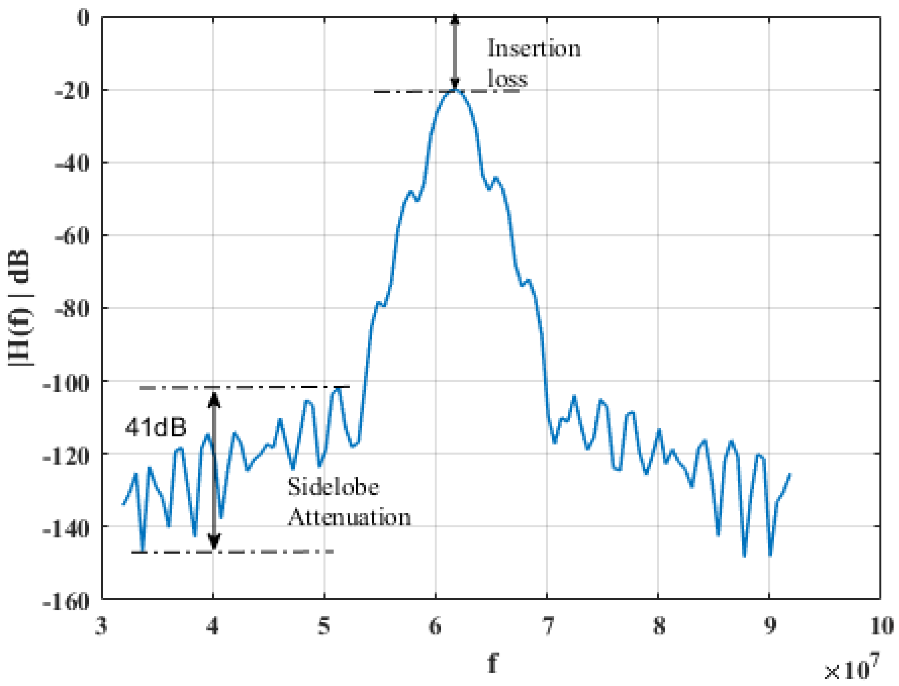
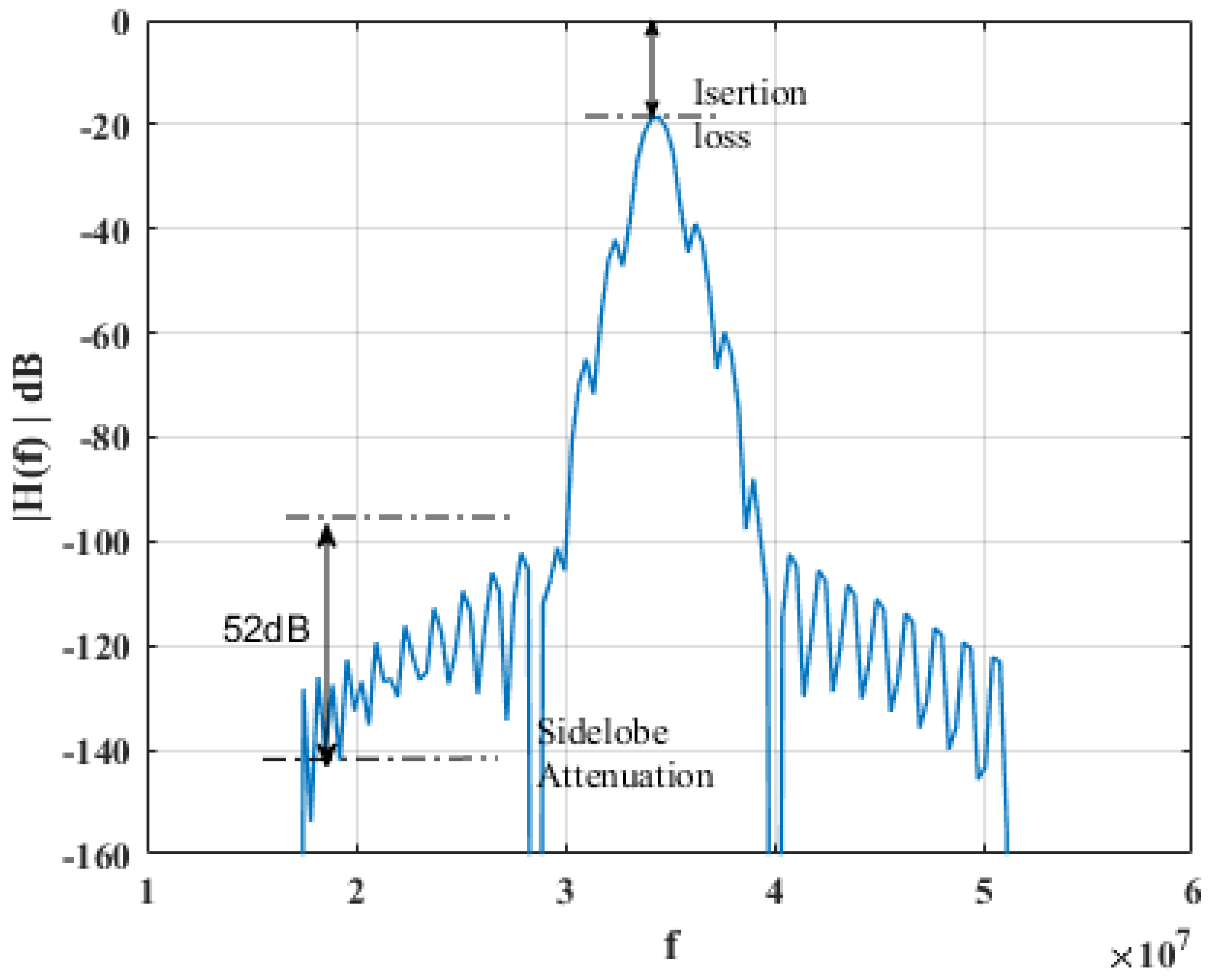
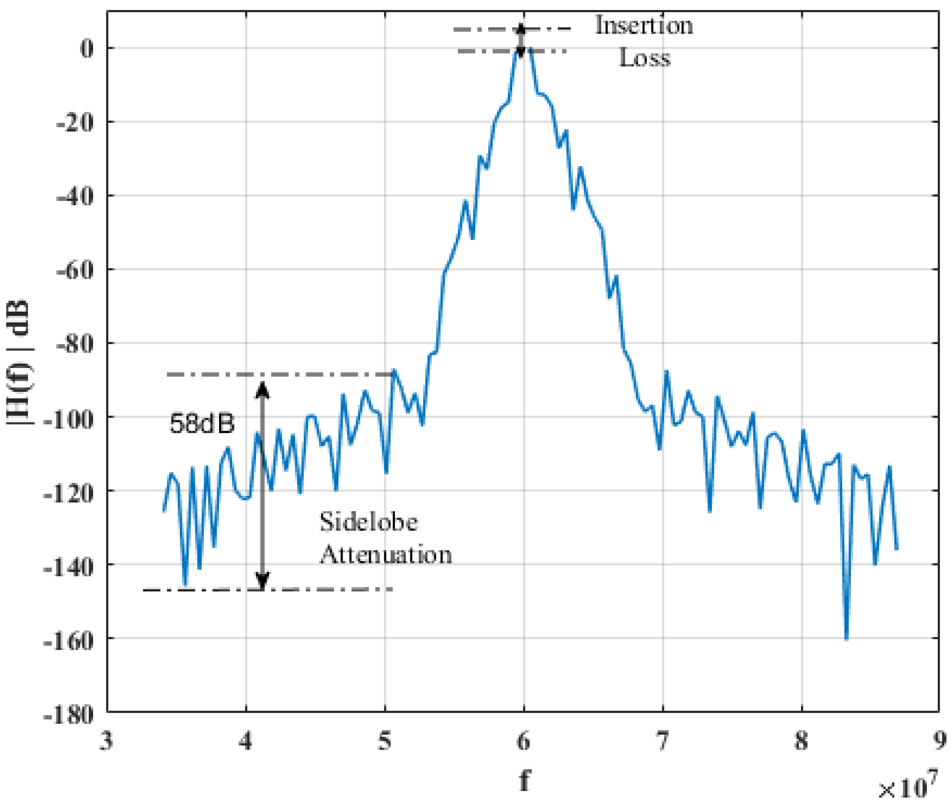
| Insertion loss | −19 | −20 | −6 |
| Sidelobe attenuation (dB) | 41 | 52 | 58 |
| Advantages | Disadvantages |
|---|---|
| Complicated conversion of the signal processed is eliminated, which may eliminate the signal distortion. | Limitation on bandwidth values. |
| Small size. | Limitation on the number of input/output IDTs fingers. |
| Low cost. | The center frequency and wavelet scale are dependent variables which pose a challenge in parameter selection. |
| Good temperature stability. | The sound electricity reclamation and insertion loss are two trade-offs related to ECC. |
| High reliability and reproducibility. | The symmetry of frequency response is another challenge in choosing substrate material, as it depends on the ECC value. |
Publisher’s Note: MDPI stays neutral with regard to jurisdictional claims in published maps and institutional affiliations. |
© 2022 by the authors. Licensee MDPI, Basel, Switzerland. This article is an open access article distributed under the terms and conditions of the Creative Commons Attribution (CC BY) license (https://creativecommons.org/licenses/by/4.0/).
Share and Cite
Ali, H.A.; Elsherbini, M.M.; Ibrahem, M.I. Wavelet Transform Processor Based Surface Acoustic Wave Devices. Energies 2022, 15, 8986. https://doi.org/10.3390/en15238986
Ali HA, Elsherbini MM, Ibrahem MI. Wavelet Transform Processor Based Surface Acoustic Wave Devices. Energies. 2022; 15(23):8986. https://doi.org/10.3390/en15238986
Chicago/Turabian StyleAli, Hagar A., Moataz M. Elsherbini, and Mohamed I. Ibrahem. 2022. "Wavelet Transform Processor Based Surface Acoustic Wave Devices" Energies 15, no. 23: 8986. https://doi.org/10.3390/en15238986
APA StyleAli, H. A., Elsherbini, M. M., & Ibrahem, M. I. (2022). Wavelet Transform Processor Based Surface Acoustic Wave Devices. Energies, 15(23), 8986. https://doi.org/10.3390/en15238986